Damping Effect Coupled with the Internal Translator Mass of Linear Generator-Based Wave Energy Converters


Abstract
1. Introduction
2. Materials and Methods
2.1. Energy Capture Theory
2.2. Numerical Modeling of the Wave Energy Converter
2.2.1. Research Site and Model Configuration
2.2.2. Model Configuration of the Wave Energy Converter
2.2.3. Model Configuration of the Wave Energy Converter
2.3. Research Object
3. Results and Discussion
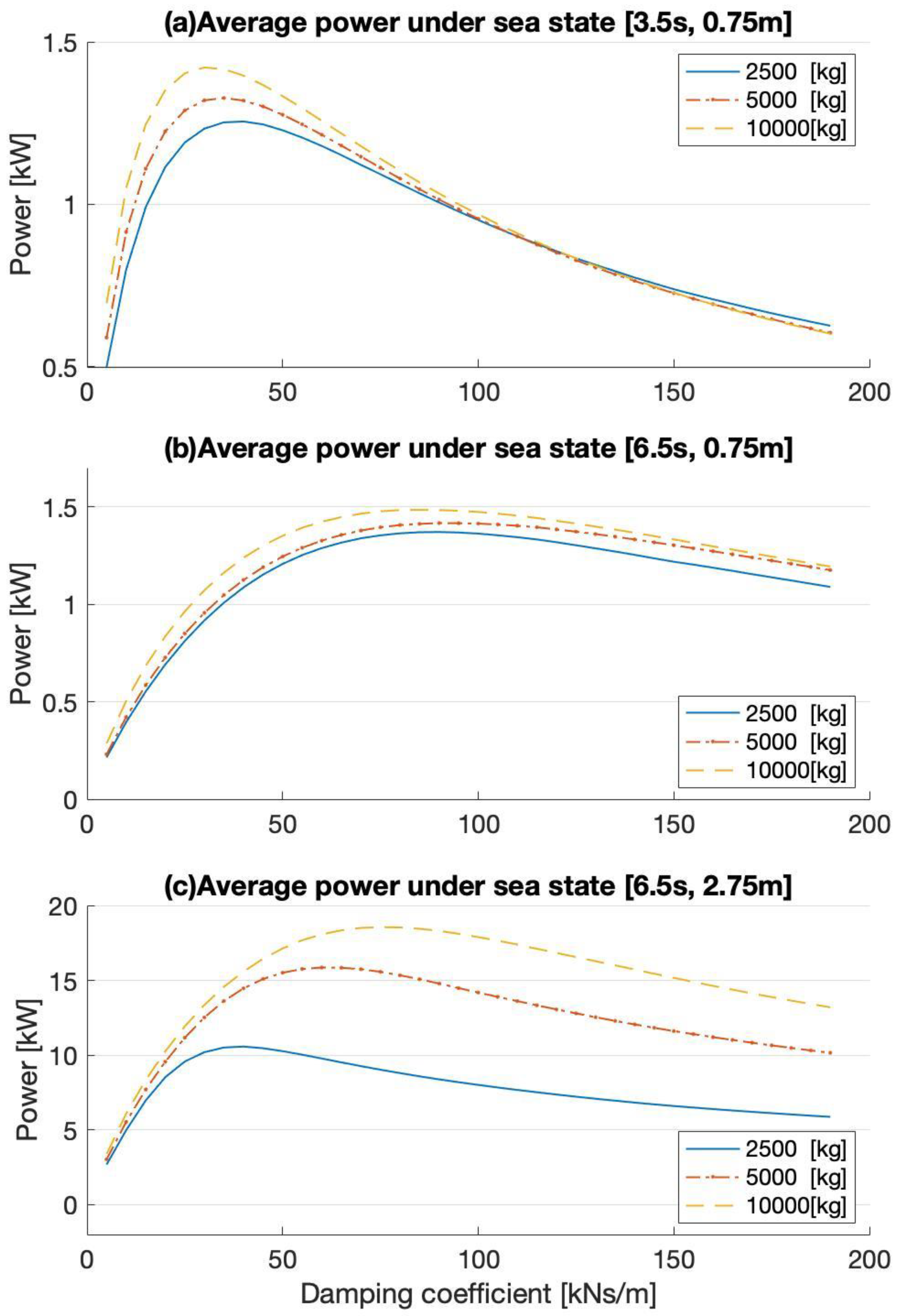
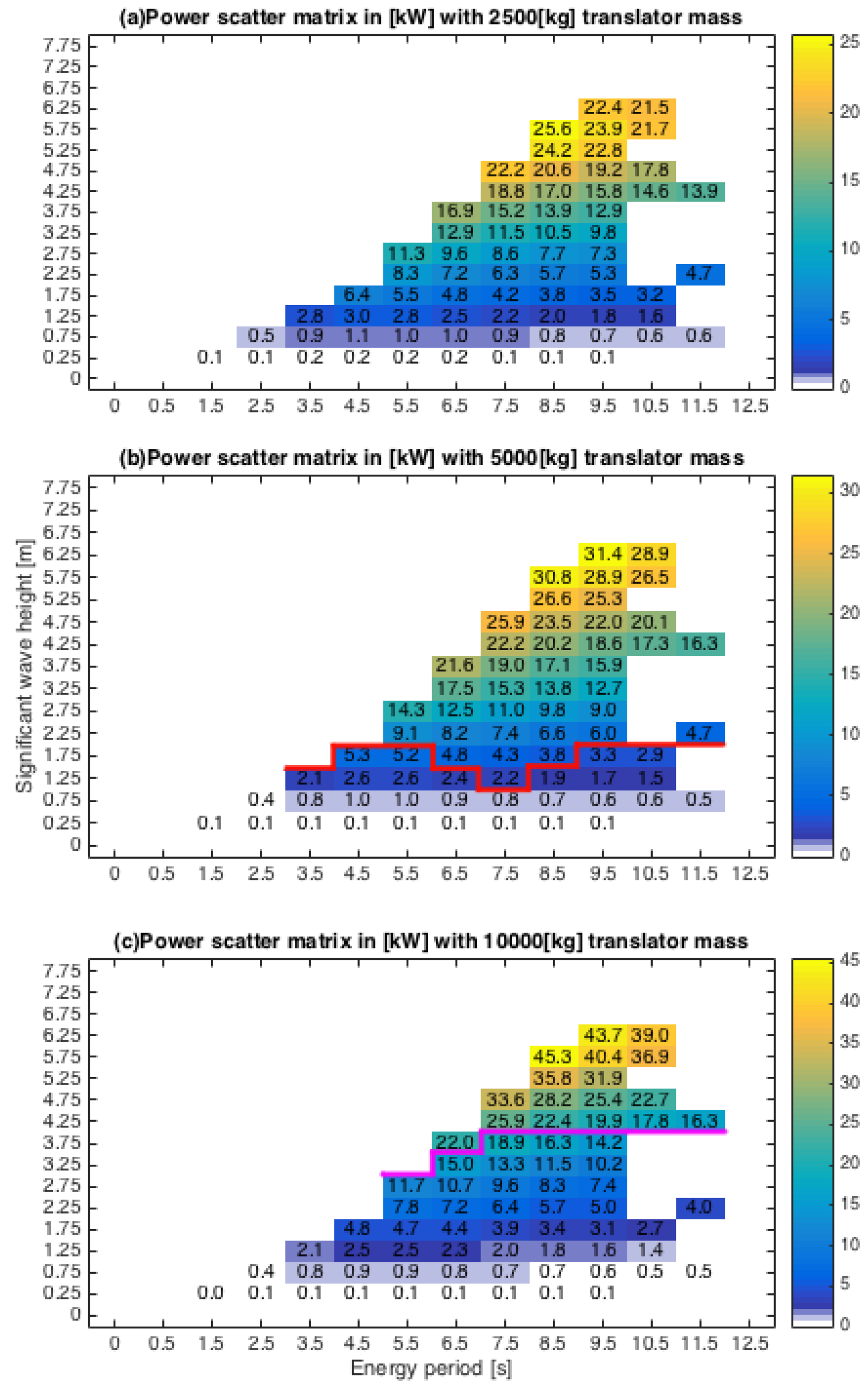
3.1. Damping Effect Coupled with Varied Translator Mass
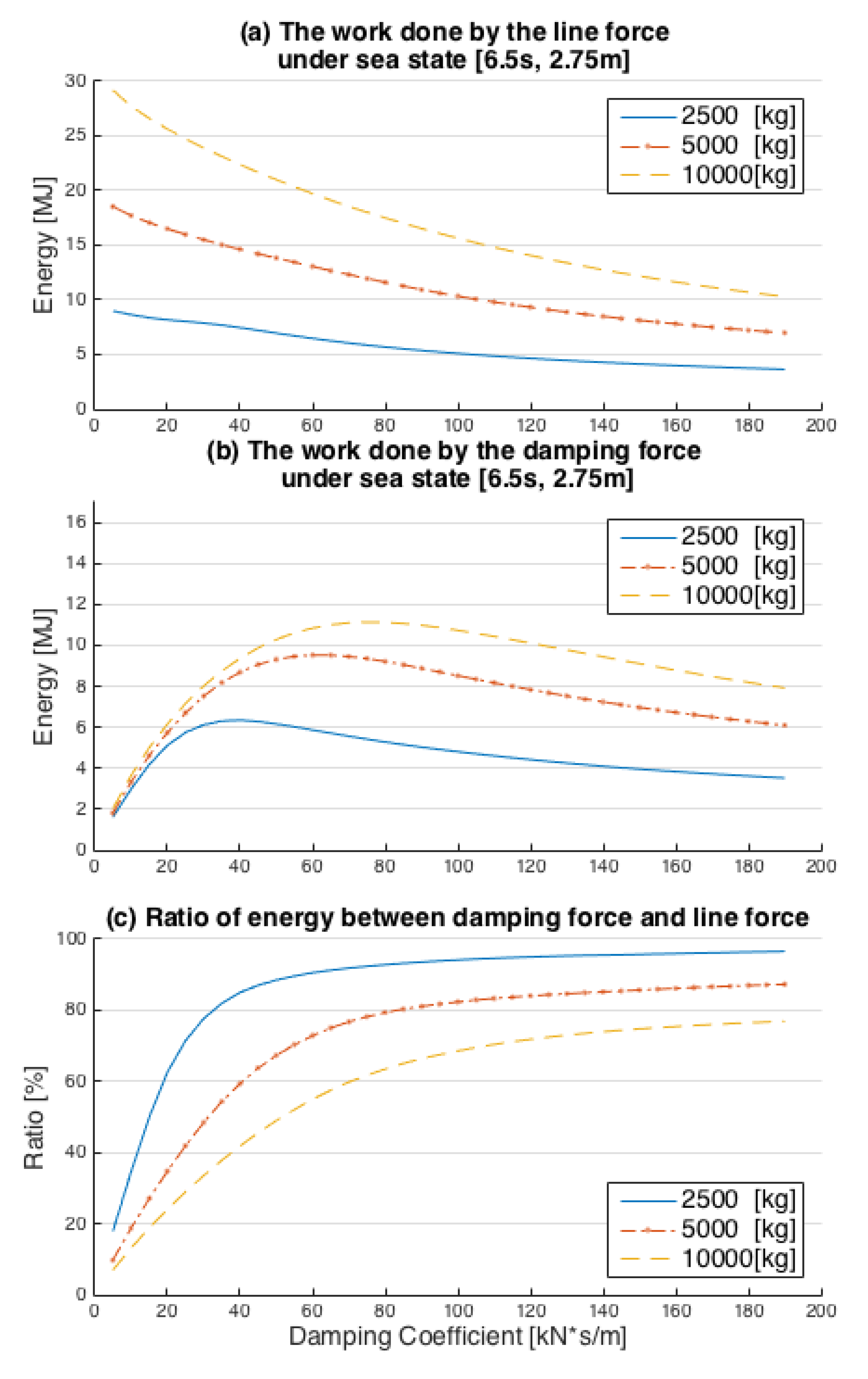
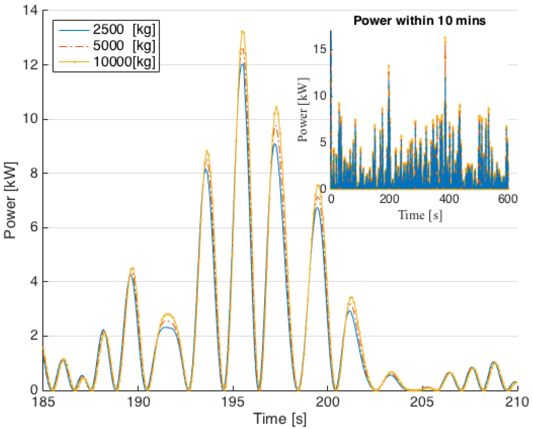
3.2. Coupled Impact on WEC Performance
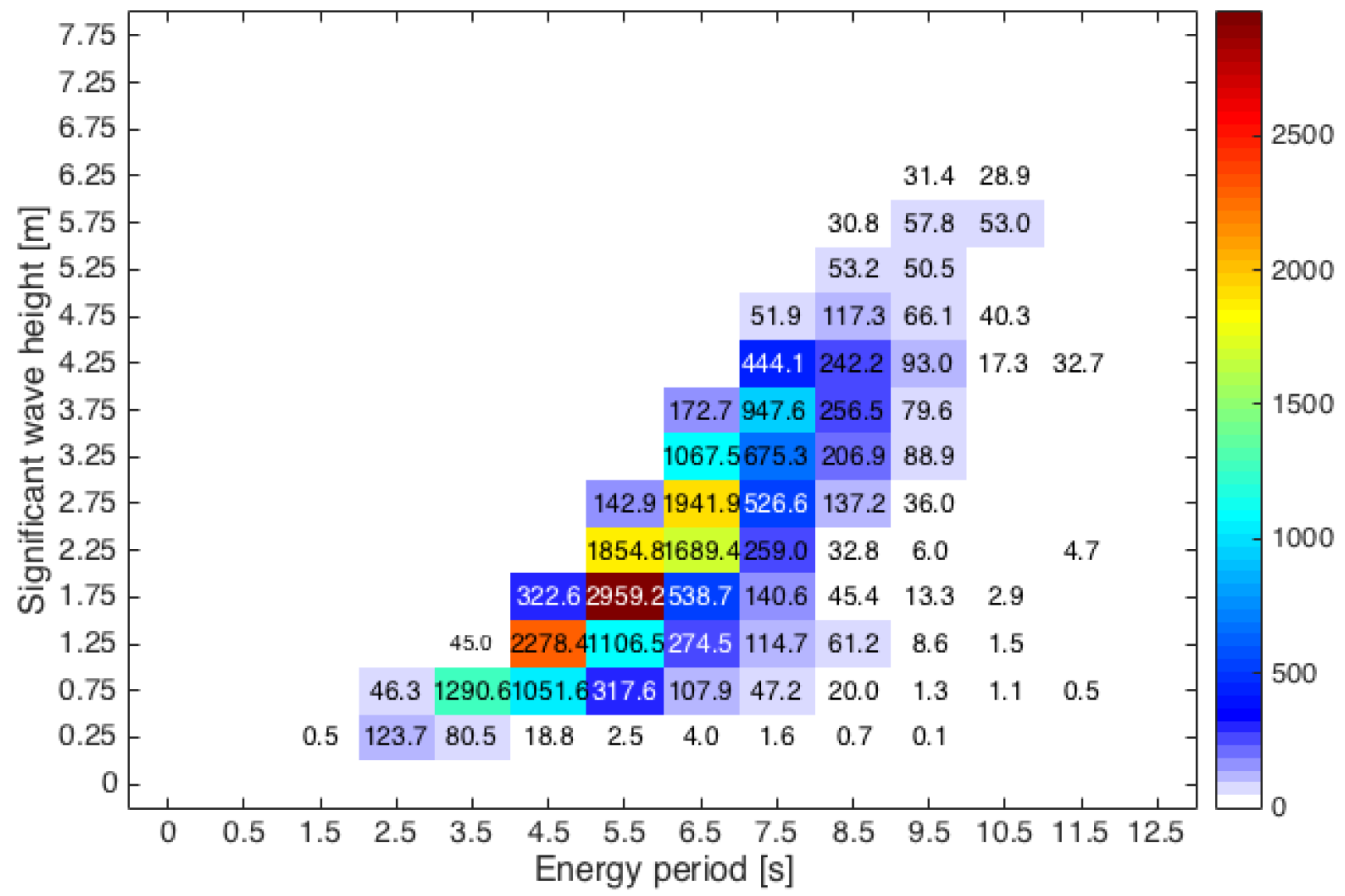
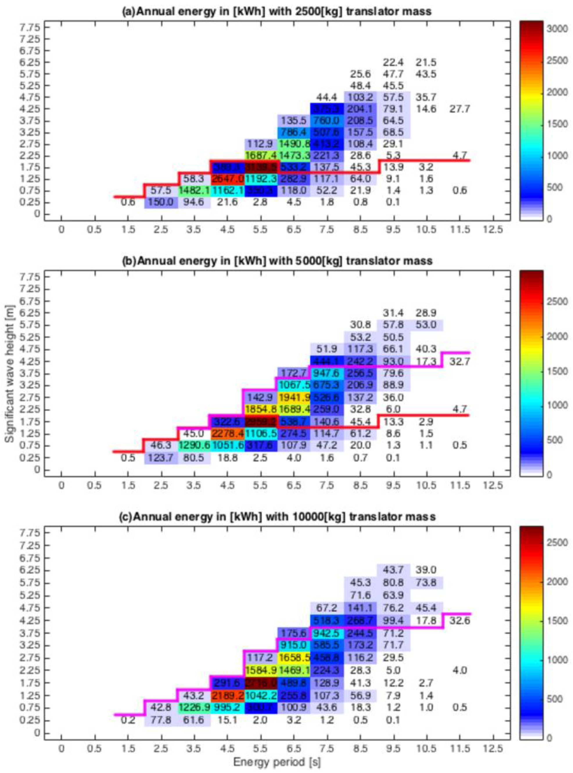
3.2.1. Annual Energy Production
3.2.2. Annual Energy Production with Varied Translator Mass
4. Conclusions
Author Contributions
Funding
Conflicts of Interest
References
- Mustapa, M.A.; Yaakob, O.B.; Ahmed, Y.M.; Rheem, C.K.; Koh, K.K.; Faizul, A.A. Wave energy device and breakwater integration: A review. Renew. Sustain. Energy Rev. 2017, 77, 43–58. [Google Scholar] [CrossRef]
- Penalba, M.; Ringwood, J.V. A review of wave-to-wire models for wave energy converters. Energies 2016, 9, 506–551. [Google Scholar] [CrossRef]
- Wang, L.; Isberg, J.; Tedeschi, E. Review of control strategies for wave energy conversion systems and their validation: The wave-to-wire approach. Renew. Sustain. Energy Rev. 2018, 81, 366–379. [Google Scholar] [CrossRef]
- Ahamed, R.; McKee, K.; Howard, I. Advancements of wave energy converters based on power take off (PTO) systems: A review. Ocean Eng. 2020, 204, 1–25. [Google Scholar] [CrossRef]
- Falcão, A.F.O. Wave energy utilization: A review of the technologies. Renew. Sustain. Energy Rev. 2010, 14, 899–918. [Google Scholar]
- Falcão, A.F.O.; Henriques, J.C.C. Oscillating-water-column wave energy converters and air turbines: A review. Renew Energy 2016, 85, 1391–1424. [Google Scholar] [CrossRef]
- Zabala, I.; Henriques, J.C.C.; Blanco, J.M.; Gomez, A.; Gato, L.M.C.; Bidaguren, I.; Falcão, A.F.O.; Amezaga, A.; Gomes, R.P.F. Wave-induced real-fluid effects in marine energy converters: Review and application to OWC devices. Renew. Sustain. Energy Rev. 2019, 111, 535–549. [Google Scholar] [CrossRef]
- Contestabile, P.; Crispino, G.; Lauro, E.D.; Ferrante, V.; Gisonni, C.; Vicinanza, D. Overtopping breakwater for wave Energy Conversion: Review of state of art, recent advancements and what lies ahead. Renew. Energy 2020, 147, 705–718. [Google Scholar] [CrossRef]
- Temiz, I.; Leijon, J.; Ekergård, B.; Boström, C. Economic aspects of latching control for a wave energy converter with a direct drive linear generator power take-off. Renew. Energy 2018, 128, 57–67. [Google Scholar] [CrossRef]
- Leijon, M.; Danielsson, O.; Eriksson, M.; Thorburn, K.; Bernhoff, H.; Isberg, J. An electrical approach to wave energy conversion. Renew. Energy 2006, 31, 1309–1319. [Google Scholar] [CrossRef]
- Chen, B.; Bruce, T.; Greated, C.A.; Kang, H. Dynamic behavior of a wave power buoy with interior on-board linear generator. Ocean Eng. 2017, 129, 374–381. [Google Scholar] [CrossRef]
- Hong, Y.; Hultman, E.; Castellucci, V. Status update of the wave energy research at Uppsala University. In Proceedings of the 10th European Wave and Tidal Conference, Aalborg, Denmark, 2–5 September 2013. [Google Scholar]
- Parwal, A.; Remouit, F.; Hong, Y. Wave energy research at Uppsala University and the Lysekil Research Site, Sweden: A status update. In Proceedings of the 11th European Wave and Tidal Energy Conference, Nantes, France, 6–11 September 2015. [Google Scholar]
- Lejerskog, E.; Gravrokmo, H.; Savin, A. Lysekil research site, Sweden: A status update. In Proceedings of the 9th European Wave and Tidal Energy Conference, Southampton, UK, 5–9 September 2011. [Google Scholar]
- Hong, Y.; Waters, R.; Boström, C.; Eriksson, M.; Engström, J.; Leijon, M. Review on electrical control strategies for wave energy converting systems. Renew. Sustain. Energy Rev. 2014, 31, 329–342. [Google Scholar] [CrossRef]
- Bostrom, C.; Svensson, O.; Rahm, M.; Lejerskog, E.; Savin, A.; Stromstedt, E. Design proposal of electrical system for linear generator wave power plants. Conf. IEEE Ind. Electron. 2009, 35, 4393–4398. [Google Scholar]
- Son, D.; Yeung, R.W. Real-time implementation and validation of optimal damping control for a permanent-magnet linear generator in wave energy extraction. J. Appl. Phys. 2017, 208, 571–579. [Google Scholar] [CrossRef]
- Ekström, R.; Ekergård, B.; Leijon, M. Electrical damping of linear generators for wave energy converters—A review. Renew. Sustain. Energy Rev. 2015, 42, 116–128. [Google Scholar] [CrossRef]
- Pan, J.F.; Li, Q.L.; Wu, X.Y.; Cheung, N.; Qiu, L. Complementary power generation of double linear switched reluctance generators for wave power exploitation. Int. J. Electr. Power Energy Syst. 2019, 106, 33–44. [Google Scholar] [CrossRef]
- Gao, Y.P.; Shao, S.Q.; Zou, H.M.; Tang, M.S.; Xu, H.B.; Tian, C.Q. A fully floating system for a wave energy converter with direct-driven linear generator. Energy 2016, 95, 99–109. [Google Scholar] [CrossRef]
- Sheng, W.A. Wave energy conversion and hydrodynamics modelling technologies: A review. Renew. Sustain. Energy Rev. 2019, 109, 482–498. [Google Scholar] [CrossRef]
- Wamit, Inc. Available online: https://www.wamit.com/ (accessed on 1 July 2019).
- Falnes, J. Ocean Waves and Oscillating Systems: Linear Interactions Including Wave-Energy Extraction, 3rd ed.; Cambridge University Press: Cambridge, UK, 2002; pp. 133–137. [Google Scholar]
- Barstow, S.F.; Mørk, G.; Lønseth, L.; Mathisen, J.P.; Schjølberg, P. The role of satellite wave data in the WORLDWAVES project. In Proceedings of the 5th International Symposium on Ocean Wave Measurement and Analysis, Madrid, Spain, 1–3 July 2005. [Google Scholar]
- Oceanogr, J.P. The WAM Model—A third generation wave prediction model. J. Phys. Oceanogr. 1988, 18, 1775–1810. [Google Scholar]
- Claesson, L. Energi Från Havets Vågor. Efn-Report No. 21; Energiforskningsnämnden: Stockholm, Sweden, 1987. [Google Scholar]
- Waters, R.; Engström, J.; Isberg, J.; Leijon, M. Wave climate off the Swedish west coast. Renew. Energy 2009, 34, 1600–1606. [Google Scholar] [CrossRef]
- Eriksson, M. Modelling and Experimental Verification of Direct Drive Wave Energy Conversion. Ph.D. Thesis, Uppsala University, Uppsala, Sweden, 2007. [Google Scholar]
- Eriksson, M.; Waters, R.; Svensson, O.; Isberg, J.; Leijon, M. Wave power absorption: Experiments in open sea and simulation. J. Appl. Phys. 2007, 102, 102–106. [Google Scholar] [CrossRef]
- Hong, Y.; Eriksson, M.; Castellucci, V.; Boström, C.; Waters, R. Linear generator-based wave energy converter model with experimental verification and three loading strategies. IET Renew. Power Gener. 2015, 10, 349–359. [Google Scholar] [CrossRef]
- Castellucci, V.; García-Terán, J.; Eriksson, M.; Padman, L.; Waters, R. Influence of sea state and tidal height on wave power absorption. IEEE J. Ocean. Eng. 2016, 42, 1–8. [Google Scholar] [CrossRef]
- Hong, Y. Numerical Modelling and Mechanical Studies on a Point Absorber Type Wave Energy Converter. Ph.D. Thesis, Uppsala University, Uppsala, Sweden, 2016. [Google Scholar]


| Parameter | Value |
|---|---|
| Vertical stator length, (mm) | 2000 |
| Vertical translator length, (mm) | 2000 |
| Translator mass, (kg) | 2700 |
| Air gap, (mm) | 3 |
| Pole width, (mm) | 50 |
| Generator resistance, (Ω) | 1 ± 1.5% |
| Generator inductance, (mH) | 20 |
| Spring coefficient for upper end stop, (kN/m) | 243 |
| Spring coefficient for lower end stop, (kN/m) | 215 |
| Buoy diameter, D (m) | 4 |
| Buoy mass, (kg) | 6300 |
| Damped natural frequency, (rad/s) | 2.2 |
| (a) | ||
| Translator Mass (kg) | Optimal Damping Coefficient (kNs/m) | The Average Power for the Optimal Damping (kW) |
| 2500 | 35 | 1.08 |
| 5000 | 40 | 0.98 |
| 10,000 | 30 | 0.96 |
| (b) | ||
| Translator Mass (kg) | Optimal Damping Coefficient (kNs/m) | The Average Power for the Optimal Damping (kW) |
| 2500 | 45 | 9.01 |
| 5000 | 55 | 10.02 |
| 10,000 | 85 | 10.34 |
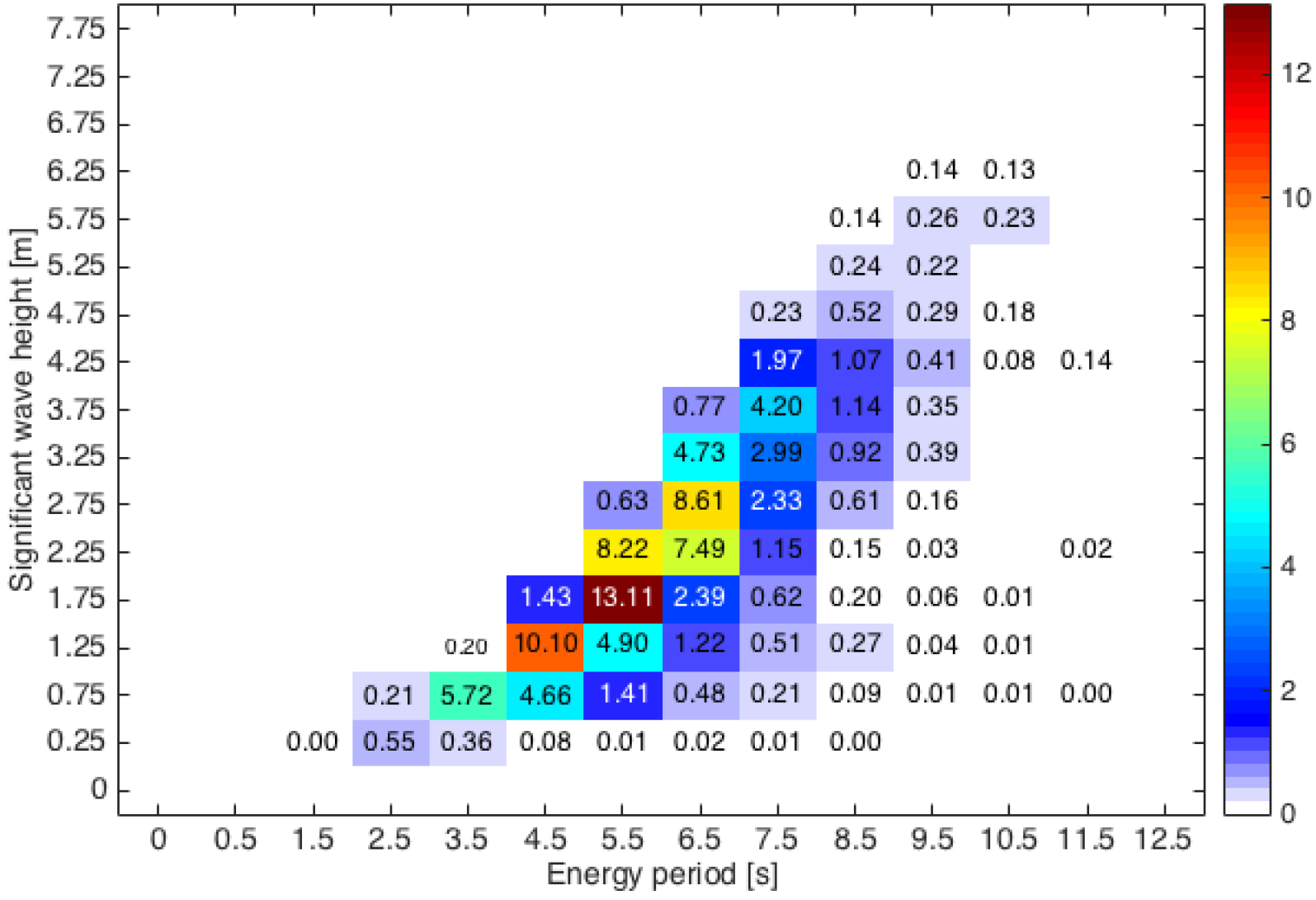
| Order | Wave Period (s) | Wave Height (m) | Annual Energy Production (MWh) | Percentage (%) |
|---|---|---|---|---|
| 1 | 5.50 | 1.75 | 2.96 | 13.11 |
| 2 | 4.50 | 1.25 | 2.28 | 10.10 |
| 3 | 6.50 | 2.75 | 1.94 | 8.61 |
| 4 | 5.50 | 2.25 | 1.85 | 8.22 |
| 5 | 6.50 | 2.25 | 1.69 | 7.49 |
| 6 | 3.50 | 2.75 | 1.29 | 5.72 |
| Translator Mass (kg) | Annual Energy Production (MWh) |
|---|---|
| 2500 | 21.62 |
| 5000 | 22.57 |
| 10,000 | 20.83 |
© 2020 by the authors. Licensee MDPI, Basel, Switzerland. This article is an open access article distributed under the terms and conditions of the Creative Commons Attribution (CC BY) license (http://creativecommons.org/licenses/by/4.0/).
Share and Cite
Hong, Y.; Eriksson, M.; Boström, C.; Pan, J.; Liu, Y.; Waters, R. Damping Effect Coupled with the Internal Translator Mass of Linear Generator-Based Wave Energy Converters. Energies 2020, 13, 4424. https://doi.org/10.3390/en13174424
Hong Y, Eriksson M, Boström C, Pan J, Liu Y, Waters R. Damping Effect Coupled with the Internal Translator Mass of Linear Generator-Based Wave Energy Converters. Energies. 2020; 13(17):4424. https://doi.org/10.3390/en13174424
Chicago/Turabian StyleHong, Yue, Mikael Eriksson, Cecilia Boström, Jianfei Pan, Yun Liu, and Rafael Waters. 2020. "Damping Effect Coupled with the Internal Translator Mass of Linear Generator-Based Wave Energy Converters" Energies 13, no. 17: 4424. https://doi.org/10.3390/en13174424
APA StyleHong, Y., Eriksson, M., Boström, C., Pan, J., Liu, Y., & Waters, R. (2020). Damping Effect Coupled with the Internal Translator Mass of Linear Generator-Based Wave Energy Converters. Energies, 13(17), 4424. https://doi.org/10.3390/en13174424