Article

Process Modelling and Simulation of Waste Gasification-Based Flexible Polygeneration Facilities for Power, Heat and Biofuels Production

by
Chaudhary Awais Salman
1,* and
Ch Bilal Omer
2
1
School of Business, Society and Engineering, Mälardalen University, SE 721 23 Västerås, Sweden
2
Kot Addu Power Company Limited (KAPCO), Kot Addu 34050, Pakistan
*
Author to whom correspondence should be addressed.
Energies 2020, 13(16), 4264; https://doi.org/10.3390/en13164264
Submission received: 19 July 2020 / Revised: 7 August 2020 / Accepted: 13 August 2020 / Published: 18 August 2020

Abstract

:
There is increasing interest in the harnessing of energy from waste owing to the increase in global waste generation and inadequate currently implemented waste disposal practices, such as composting, landfilling or dumping. The purpose of this study is to provide a modelling and simulation framework to analyze the technical potential of treating municipal solid waste (MSW) and refuse-derived fuel (RDF) for the polygeneration of biofuels along with district heating (DH) and power. A flexible waste gasification polygeneration facility is proposed in this study. Two types of waste—MSW and RDF—are used as feedstock for the polygeneration process. Three different gasifiers—the entrained flow gasifier (EFG), circulating fluidized bed gasifier (CFBG) and dual fluidized bed gasifier (DFBG)—are compared. The polygeneration process is designed to produce DH, power and biofuels (methane, methanol/dimethyl ether, gasoline or diesel and ammonia). Aspen Plus is used for the modelling and simulation of the polygeneration processes. Four cases with different combinations of DH, power and biofuels are assessed. The EFG shows higher energy efficiency when the polygeneration process provides DH alongside power and biofuels, whereas the DFBG and CFBG show higher efficiency when only power and biofuels are produced. RDF waste shows higher efficiency as feedstock than MSW in polygeneration process.

Graphical Abstract

1. Introduction

Approximately 2.0 billion tonnes of municipal solid waste (MSW) is generated globally every year—this figure is forecast to reach 3.4 billion tonnes annually in 2050 [1]. MSW contains significant amounts of non-recyclable organic and inorganic content. There is a growing interest in recovering energy and nutrients from MSW owing to the increase in waste generation and inadequate waste disposal practices currently implemented, such as composting, landfilling and dumping [2]. MSW is a heterogeneous mixture of waste fractions, thus, the conversion of MSW to energy requires the source separation of the non-recyclable organic fraction from the recyclable organic fraction (such as metal, glass, etc.). MSW also has high moisture and ash content and low heating value. The heterogenous nature of MSW makes it difficult to convert it into energy [3]. The properties of MSW can be improved by processing it into refuse-derived fuel (RDF) through physiochemical treatments, such as shredding, magnetic sorting, grinding, screening and bag ripping [4], resulting in low moisture and ash content and higher heating value than MSW.
Some developed countries (Sweden, Denmark and Japan) have state-of-the-art waste management systems with well-established waste collection and source-separation practices [1]. Consequently, the production of RDF through MSW processing is easier in these countries than in low-income countries. In addition, some developed countries, such as the United States, Australia, and Canada, still dispose of 50% of their waste to landfill [1]. Thus, not every country has the ability and existing structure to prepare RDF from MSW. This study therefore considers both MSW and RDF as potential feedstocks for polygeneration facilities.
Incineration of waste for heat or power production is a commercially mature technology; however, there is a growing interest among researchers and industrial stakeholders in designing waste-to-biofuels processes [5]. The efficiency of waste combustion to produce electrical power is ~30%. The overall efficiency increases with the co-production of district heating (DH) with power, but not all regions require DH, and its production depends on the local demand. Different thermochemical processes can convert MSW and RDF into biofuels, for instance, gasification, pyrolysis, hydrothermal liquefaction, hydrothermal carbonization and torrefaction [6]. This study uses the gasification process for the treatment of MSW and RDF. Gasification converts waste to syngas, which provides flexibility to produce a variety of biofuels along with DH and power. Syngas from waste gasification can be converted to power at a higher efficiency than waste combustion [7,8]. However, waste gasification remains in the research and development phase, with only a few demonstration plants currently in operation. The overall energy efficiency of waste gasification can also be increased by the simultaneous conversion of syngas to multiple products (biofuels, power and DH) in polygeneration plants [9].
Polygeneration is the integration of various processes to produce multiple products simultaneously [10]. The overall aim of polygeneration process design is to increase the conversion efficiency by the production of value-added products and to enhance the economic outcomes. The secondary aim of polygeneration processes is to increase the system flexibility in terms of products, operation and feedstock. According to Ciuta et al. [11], the best path forward for waste gasification is to combine gas turbine and biofuel synthesis. The net system efficiency of the gasification process may also increase through polygeneration of DH, power and other bio-based products [9].
Several authors conducted polygeneration-based studies with coal as a feedstock [12,13,14,15,16,17,18,19,20,21]. Gootz et al. [12] studied the polygeneration of coal to liquid biofuels based on entrained flow gasification. Buttler at al. [13] evaluated the coal-based polygeneration plant by integrating a gasification-combined cycle with electrolysis and natural gas synthesis. Yu et al. [14] analyzed the polygeneration of Fischer–Tropsch (FT) fuels with power from coal gasification. Narvez et al. [15] and Li et al. [16] studied the polygeneration plant with methanol and power production. A coal pyrolysis-based polygeneration plant was analyzed by Guo et al. [17]. Li et al. [18] designed a coal to natural gas and methanol-based polygeneration plant and established the techno-economic feasibility. Huang et al. [19] designed coal-based polygeneration processes for chemicals and power. Heinz et al. [20] simulated a coal-based polygeneration plant with fluidized bed gasification. Kim et al. [21] evaluated the polygeneration of methanol, power and heat from coke oven gas.
Biomass-based polygeneration plants have also been studied by numerous authors [22,23,24,25,26]. Fan et al. [22] studied the biomass- and coal-based polygeneration plant for power and natural gas. Meerman et al. [23] extensively studied the polygeneration of various biofuels along with power from both biomass and coal. Sahoo et al. [24] developed the hybrid polygeneration plant for power, cooling and desalination by integrating solar with a biomass power plant. Jana et al. [25] studied the feasibility of an agricultural-based polygeneration plant. In a different study, Jana et al. [26] reported the sustainability of polygeneration design. Gladysz et al. [27] studied polygeneration systems based on thermochemical conversion of biomass.
There are few studies considering waste as feedstock for a polygeneration plant. Villarroel-Schneider et al. [28] designed a biogas-based polygeneration plant using dairy farm waste. Jana et al. [29] performed the life-cycle assessment of an agricultural waste-based polygeneration plant. Fuente et al. [30] designed a concentrated solar and waste-based polygeneration plant, mainly for power production. To our knowledge, there are no reports in the literature that consider MSW and RDF conversion to multiple products through flexible polygeneration facilities.
There are various types of gasifiers that can treat waste: fixed bed, fluidized bed, and entrained flow gasifiers (EFGs) [31]. Waste feedstock differs from biomass and coal in that the size and properties of the waste are heterogeneous. Waste also has higher inorganic content, and its heating value is generally lower due to the high amount of ash and moisture. It is generally perceived that circulating fluidized bed gasifiers (CFBG) or bubbling fluidized bed gasifiers (BFBG) produce high-quality syngas for biofuel synthesis. However, CFBG and BFBG require an air separation unit (ASU) to produce the nitrogen-free syngas. The dual fluidized bed gasifier (DFBG) is another type of gasifier that contains two separate reactors for gasification and combustion and can therefore produce syngas without nitrogen. Fluidized bed gasification also produces tar, which must be removed from syngas in downstream processes prior to synthesis of biofuels. The EFG is another type of gasifier, which operates at high pressure and temperature and can produce tar-free syngas. However, the EFG requires feed pretreatment, e.g., size reduction through grinding, torrefaction, and drying. Performance of different gasifiers has previously been compared for the production of methane through syngas from biomass or coal-based feedstock [32,33,34]. There has been little or no consideration of evaluating suitable gasifiers for RDF to biofuels or MSW to biofuels processes.
The purpose of this study is to design and simulate RDF and MSW-based gasification polygeneration plants for DH, power and biofuels production. Methane, methanol/dimethyl ether (DME), FT fuels (diesel or gasoline) and ammonia from the waste polygeneration plant are considered as potential biofuels. Waste polygeneration processes are designed and compared with three different gasifiers—the EFG, CFBG, and DFBG. The following section describes the methodology for the process design, simulation approach and the studied cases, and is followed by results, discussion and conclusions.

2. Materials and Methods

2.1. Polygeneration Concepts

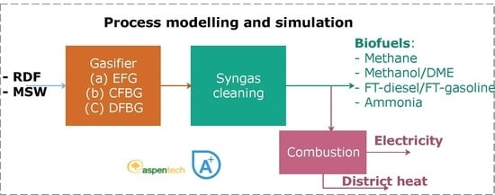
This section provides a technical description of the waste-based polygeneration concepts simulated in this study. Figure 1 presents the simplified process flow diagram of the waste-based polygeneration concept. Two types of feed—RDF and MSW—are considered and three different gasifiers—the EFG, CFBG, and DFBG—are evaluated.

2.2. Ultimate and Proximate Analyses of MSW and RDF

As described above, two different types of waste were selected as the raw material: RDF and MSW. The ultimate and proximate analyses of RDF and MSW used for simulations are displayed in Table 1.
Higher heating value (HHV) and lower heating value (LHV) of RDF and MSW are estimated using the following relations [36,37]:
HHV   ( MJ kg ) = ( 0.3289 + 0.0117 ( 100 C daf ) 0.25 ) C ab + 1.129 ( H O 10 ) + 0.105 S
LHV   ( MJ kg ) = HHV [ ( 18.015 × H % 2 ) + Moisture ( % ) ] × 5.85 100
where C, H and O are carbon, hydrogen and oxygen, respectively; daf refers to the dry and ash-free basis, and ab refers to the ash-free basis.

2.3. Modelling and Simulation

This section describes the modelling and simulation approach used for the waste gasification-based polygeneration process. Aspen Plus was used for modelling and simulation [38].

2.3.1. Air Separation Unit Modelling

The ASU was only considered for the EFG and CFBG; it was not modelled in detail in this study. Instead, the separator block of Aspen Plus was used to separate oxygen and nitrogen. The power consumed by the ASU was estimated as 0.4 kWhe/m3 oxygen [33].

2.3.2. Pretreatment (Grinding and Drying) Modelling

Size reduction of waste (up to 2 mm) was carried out as waste pretreatment through grinding in order to make it suitable for gasification. The grinding was modelled in three stages by using the three crushers and the screen unit of Aspen Plus. The power required for grinding was estimated by the crusher blocks. Both RDF and MSW contain moisture, so drying is required to achieve the optimum conditions in the gasifier. RDF and MSW were dried to 10% final moisture. The RSTOICH reactor and separator block of Aspen Plus was used to model the dryer [39]. The heat required for drying was calculated using Equation (3) [40].
h e a t d r y i n g = F C p w a s t e d T + M C p w a t e r d T + L h v M v
where, F′ is mass of waste feed in the dryer, C p w a s t e is heat capacity of dry waste, C p w a t e r is heat capacity of water, M is mass of water present in the waste, dT is difference between drying and ambient temperature, Lhv is the latent heat of vaporization of water and Mv is the amount of water evaporated. The CALCULATOR block of Aspen Plus determined the heat required for drying using Equation (3). The required heat for drying was exported from the heat recovery steam generation (HRSG) section in the form of low pressure (LP) steam.

2.3.3. Modelling of Gasifiers, Syngas Cooling, Acid Gas Removal and Water–Gas Shift Reactor

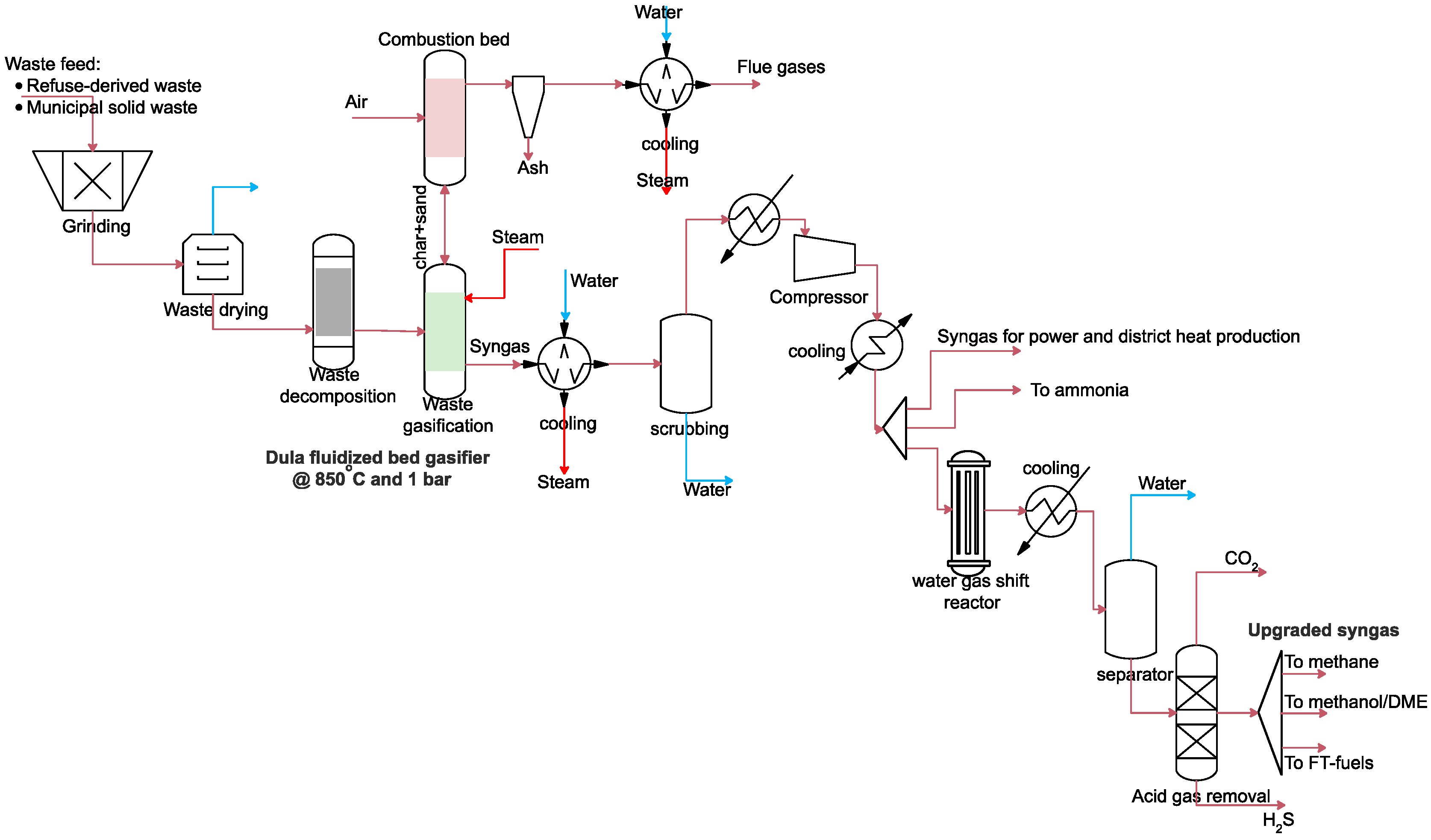
Zero-dimensional models of gasifiers—EFG, CFBG and DFBG—were developed in this study with Aspen Plus. Figure 2, Figure 3 and Figure 4 describe the process flow diagram of EFG, CFBG and DFBG, respectively. EFG and CFBG were modelled using two blocks of Aspen Plus. The RYIELD reactor decomposes the waste into its constituent elements and compounds (C, H, N, S, Cl, O, Ash and moisture). Gasification of waste was modelled by the RGIBBS reactor by assuming equilibrium conditions through minimization of Gibbs free energy. The pressure and temperature considered for EFG were 24 bar and 1300 °C [41]. For the CFBG, a temperature of 850 °C and a pressure of 1 bar were considered. Pure oxygen from ASU and steam from the HRSG section were also introduced into the gasifier.
The DFBG was modelled by using three Aspen Plus blocks: RYIELD for the decomposition of waste into its constituent elements and RGIBBS reactor for gasification and combustion. Unreacted char from the gasification reactor was transferred to the combustor. Char combustion was modelled by the RSTOICH reactor with combustion reactions at adiabatic conditions. DFBG operated at a temperature of 850 °C and a pressure of 1 bar. Air entered into the combustor reactor of DFBG, while steam was used as the oxidizing agent in the gasifier.
All the sulfur, chlorine and nitrogen present in waste was hydrogenated to hydrogen sulfide, hydrogen chloride and ammonia, respectively. Ash was removed from the syngas using the separator block. Syngas from the gasifier was cooled in three stages—in the first stage, syngas was cooled to 350 °C and waste heat was recovered in the form of steam. Syngas was then scrubbed with water in the second stage and finally, syngas was further cooled prior to the water–gas shift (WGS) reactor. The flash drum was used to remove water from syngas. Ammonia and hydrogen chloride in syngas was removed with water in the flash drum. Sulfur was removed by acid gas removal (AGR). For simplicity, the separator block was used to model AGR.
Syngas from the gasifier was split and sent to the gas turbine and HRSG section without upgradation in the WGS reaction. As CFBG and DFBG operated at atmospheric conditions, cooled syngas was compressed to 24 bar before sending it to the gas turbine section and WGS reactor. The compressor block with 85% isentropic efficiency and 95% mechanical efficiency was used to model the syngas compression. The WGS reactor was used to maintain the H2/CO ratio of syngas according to R1:
CO + H 2 O CO 2 + H 2 Δ G ° = 41   kJ / mol
The syngas was required to produce methane, methanol/DME, FT diesel and FT gasoline fuels, which require a H2/CO of 2–3 for their synthesis. Thus, for conservative assessment a H2/CO ratio of 3 was selected in this study. The REQUIL reactor of Aspen Plus was used with adiabatic and equilibrium conditions. Steam was added to the reactor. The design specification block of Aspen Plus adjusted the flow of steam to achieve the desired H2/CO ratio of syngas leaving the WGS reactor. The temperature of WGS varied between 300 and 450 °C for different cases and gasifiers. Upgraded syngas leaving the WGS reactor was cooled to 150 °C and waste heat was recovered as steam. Pure hydrogen is required for ammonia synthesis, so cooled syngas (without WGS) was sent to the ammonia synthesis island, where carbon monoxide was converted to hydrogen in the presence of steam in two shift reactors—modelling details of which are presented in Section 2.3.7.
CO2 was removed from upgrade syngas. CO2 removal can be carried out through absorption with N-methyl diethanolamine (MDEA). For simplicity, modelling of CO2 removal was omitted from this study. Instead, a separator block of Aspen Plus was used to remove 98% of CO2. The heat required for CO2 removal was considered as 4 MJ/kg CO2 removed and required heat was exported from the HRSG section [42].

2.3.4. Methane Synthesis Modelling

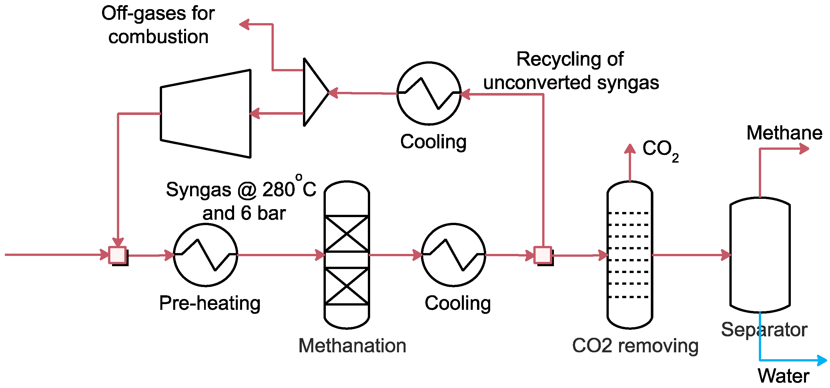
Figure 5 depicts the methane production process diagram from syngas modelled in Aspen Plus. Syngas was converted to methane in a methanation process in the presence of a catalyst. Reactions R2 and R3 occur in the reactor. Upgraded syngas was preheated to 280 °C and compressed to 6 bar prior to methanation [43]. The compressor block of Aspen Plus was used to compress syngas. The design of the compressor was beyond the scope of this study, and only the compression power required was estimated. Isentropic efficiency of 85% and mechanical efficiency of 98% were used. The RGIBBS reactor was used to model the methanation by restricting the equilibrium at 280 °C and 6 bar. Reactions R2 and R3 are exothermic, so heat must be removed from the reactor to maximize the methane yield. Vapors leaving the methanation were cooled and waste heat was recovered in the form of steam. Vapors were upgraded to 98% pure methane by using the separator blocks of Aspen Plus. 90% of unconverted gases were recycled, while the rest were sent for combustion.
CO + 3H2 → CH4 + H2O ΔH◦ = −206 kJ/mol
CO2 + 4H2 → CH4 + 2H2O ΔH◦ = −165 kJ/mol

2.3.5. Methanol/DME Synthesis Modelling

Figure 6 shows the process flow diagram for methanol and DME production from syngas modelled in Aspen Plus. Upgraded syngas from the WGS reactor was compressed to 95 bar using the compressor block of Aspen Plus. The design of the compressor was beyond the scope of this study and only the compression power required was estimated. Isentropic efficiency of 85% and mechanical efficiency of 98% were used. Compressed syngas was preheated to 220 °C for methanol synthesis [44]. The RGIBBS reactor was used for modelling of methanol synthesis from syngas by assuming the minimization of Gibbs free energy. The reaction R4 occurs in the methanol reactor. Vapors leaving the reactor were cooled to 35 °C. Unreacted gases were separated from methanol by using the flash drum of Aspen Plus. Part of the unreacted vapors was recycled while the remainder was sent for combustion. Liquid methanol from the flash drum was distilled in two stages using the separator and DSTWU block of Aspen Plus with 30 stages and 99% recovery of methanol. The off-gases from methanol distillation were recycled.
Half of the pure methanol was collected as a separated product, and the other half was converted to DME. Methanol was dehydrated to DME via R5. Liquid methanol was pumped to 56 bar and preheated to 280 °C prior to the DME synthesis reactor. The REQUIL reactor was used to model DME synthesis by assuming equilibrium conditions. Vapors leaving the reactor were cooled and condensed. DME was recovered via distillation. The DSTWU block was used to model DME purification with 30 stages and 99% recovery of DME. Unreacted methanol was pumped back to the methanol purification section.
4H2 + 2CO → 2CH3OH ΔH◦ = −181 kJ/mol
2CH3OH → CH3OCH3 + H2O ΔH◦ = −23.4 kJ/mol

2.3.6. FT Fuels Synthesis Modelling

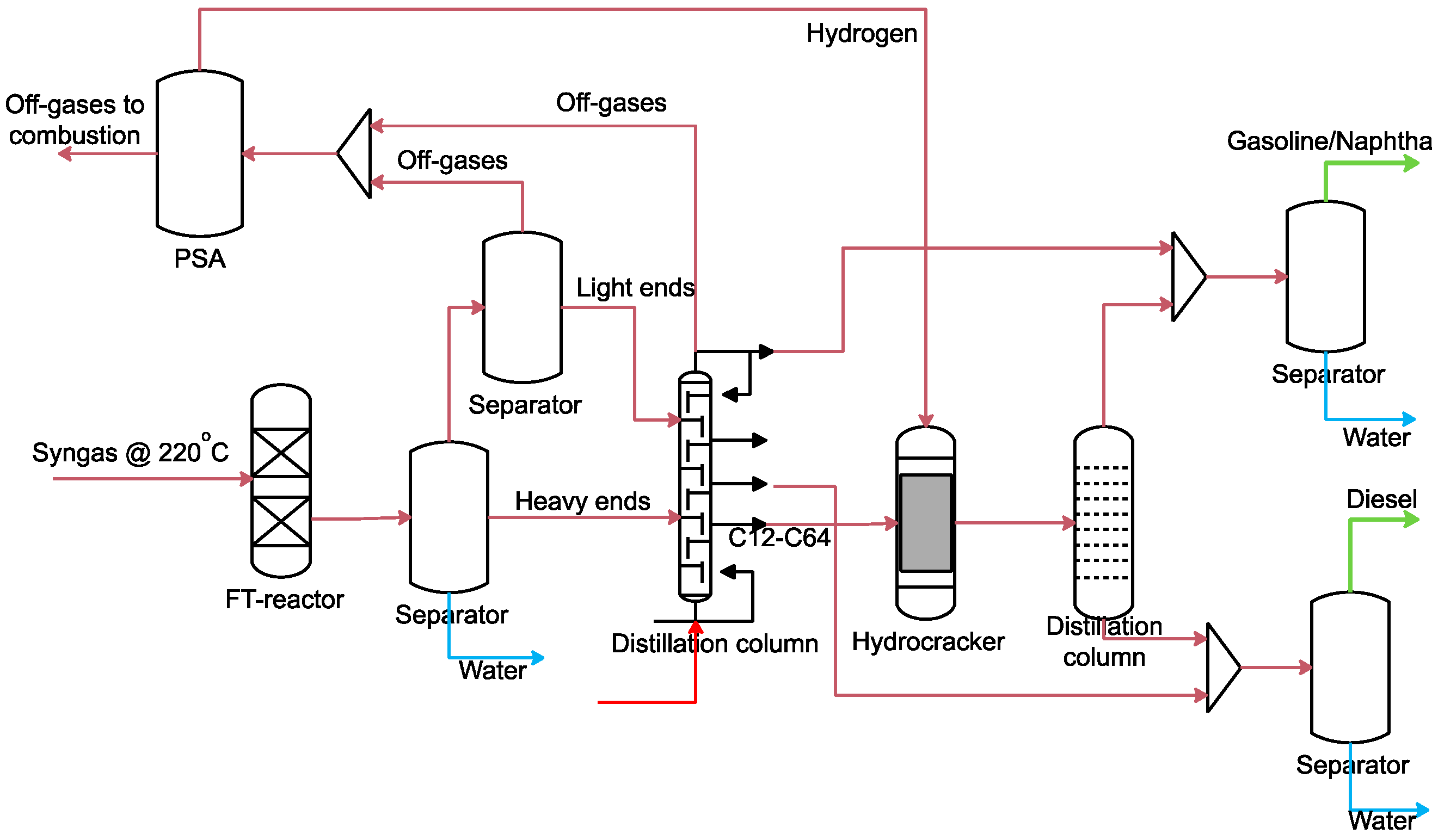
The process flow diagram of FT fuels synthesis from syngas is shown in Figure 7. Upgraded syngas was compressed to 36 bar and preheated to 220 °C for FT fuels production [45]. The FT fuels product distribution was modelled and simulated by adopting the method from Pondini et al. [45] (Figure 7). The product distribution follows the Anderson–Schultz–Flory (ASF) model with an α-value of 0.8 Equation (4) [45,46]. CO conversion is the limiting step in the FT reactor; 70% CO conversion was selected [46].
W n = n ( 1 α ) 2 α ( n 1 )
The FT fuels are composed of C1–C30+ hydrocarbons containing paraffins and olefins, according to reactions R6 and R7. The CALCULATOR block of Aspen Plus calculated the yield of FT fuels and the results were transferred to the RYIELD reactor.
Paraffins formation
nCO + (2n + 1)H2 → CnH2n+2 + nH2O
Olefins formation
nCO + 2nH2 → (—CH2—)n + nH2O
Products leaving the FT reactor were cooled by using the three-phase flash drum of Aspen Plus into the water, heavy ends and light ends. Light ends were sent to a separator block, which separated the off-gases (unreacted syngas and C1–C4) and C5–C11 contents. For simplicity, heavy ends were refined in a column modelled using the separator block. Off-gases, C5–12 and C12–C64 contents were separated in the column. C12–C64 contents of FT fuels were pumped to the hydrocracker at 50 bar. Hydrogen from off-gases was separated by pressure swing adsorption (PSA) and sent for hydrocracking of C12–C64 contents of FT fuels. The remainder of the off-gases were sent back for combustion. The RSTOICH block was used to model the hydrocracker at 50 bar and 350 °C. Diesel and gasoline were then separated and collected as final products by using the separator block of Aspen Plus.

2.3.7. Ammonia Synthesis Modelling

Figure 8 shows the process flow diagram of ammonia synthesis modelled in Aspen Plus. Syngas from the CFBG and DFBG contains a significant amount of methane, which needs to be reformed to H2 in the presence of steam (R8). Thus, a reformer was also modelled for the CFBG and DFBG only using the RSTOICH reactor in Aspen Plus.
Carbon monoxide and carbon dioxide in syngas from the reformer was converted to hydrogen via two WGS reactors: a high-temperature shift reactor (300–450 °C) and a low-temperature shift reactor (220–250 °C). The REQUIL reactor was used to model shift reactors at adiabatic conditions with a temperature approach of 20 °C. CO2 was removed via a separator and the required heat for CO2 removal was imported from the HRSG section. Hydrogen was separated via a PSA and off-gases were sent for combustion. Hydrogen was preheated to 300 °C from vapors leaving the ammonia synthesis reactor. Nitrogen from the ASU entered the ammonia synthesis reactor. The ammonia synthesis reactor operates at 300 °C and 100 bar [23].
The REQUIL reactor was used to model ammonia production from nitrogen and hydrogen via R9. Vapors leaving the ammonia synthesis reactor were cooled and waste heat was recovered in the form of steam. Ammonia was then liquefied by condensation and unreacted vapors were separated and recycled back to the reactor.
CH4 + H2O → CO + 3H2 ΔH◦ = 206 kJ/mol
N2 + 3H2 → 2NH3 ΔH◦ = −92.4 kJ/mol

2.3.8. Power and DH Production Modelling

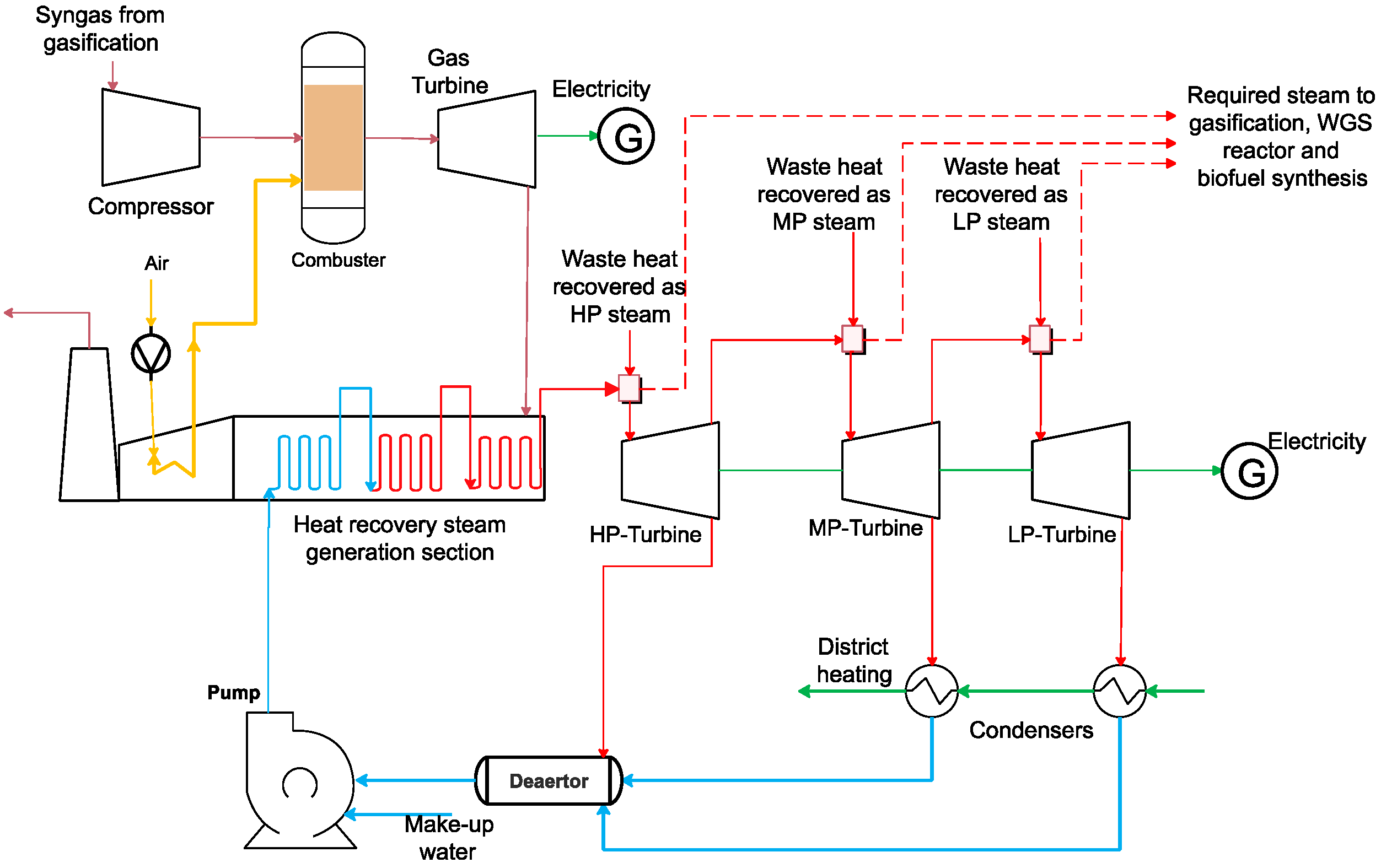
A combination of the Brayton and Rankine cycles was used for power and DH generation (Figure 9). Syngas at high pressure was combusted and expanded in the gas turbine. The heat from hot flue gases leaving the gas turbine was recovered in the form of superheated steam. Superheated steam was expanded in a series of steam turbines. Saturated steam was condensed to provide the DH. Operating pressure selected for the gas turbine was 24 bar [42]. The EFG operates at 24 bar, so syngas from the EFG was already at the required pressure, but syngas produced in the CFBG and DFBG was at atmospheric pressure and was therefore compressed to 24 bar. Isentropic efficiency of 85% and mechanical efficiency of 95% were considered for the modelling of the compressor. Compressed syngas was combusted by using the RSTOICH reactor with combustion reactions at adiabatic conditions. The air required for combustion was estimated using the CALCULATOR block. Air was preheated by steam in the HRSG section. Combustion gases were expanded in the gas turbine. A discharge pressure of 1.07 bar was considered. Isentropic efficiency of 85% and mechanical efficiency of 95% were selected for the gas turbine.
The heat from combustion gases leaving the gas turbine was recovered in the HRSG section in the form of superheated steam at 70 bar and 470 °C. Three heat exchangers—an economizer, an evaporator and a superheater—were used to recover heat in the form of steam. Water was pumped into the economizer, where it was heated to 220 °C. The evaporator converted the vapor-liquid stream to vapor. Steam was heated to 470 °C in the superheater. Three different steam pressures were used in this study: high-pressure steam at 70 bar, medium-pressure steam at 17 bar and low-pressure steam at 4 bar. Superheated steam was expanded in three turbines—high-pressure, medium-pressure and low-pressure turbines—with isentropic efficiencies of 90%, 85% and 80%, respectively, and a mechanical efficiency of 95% [32]. The steam leaving the medium-pressure and low-pressure turbines were condensed to produce the DH. Waste heat was also recovered in the biofuel synthesis section, which was introduced in steam turbines to produce extra power. Drying of waste, gasifier, WGS, CO2 removal, distillation columns and biofuel synthesis also required steam, which was exported from the HRSG.

2.4. Performance Indicators and Case Studies

The effects of the steam-to-waste ratio Equation (1) on syngas composition and biofuel synthesis for all three gasifiers—EFG, CFBG and DFBG—were estimated and reported. Similarly, the changes in syngas composition and biofuel production with the variation of equivalence ratio (ER) were also reported Equation (2).
Steam waste = Total   steam   supplied   in   gasifier   ( kg s ) Waste   entered   in   gasifer   ( kg s )
ER = ( Oxygen fuel ) used ( Oxygen fuel ) Stoichiometric
Four cases were designed to determine how the output and polygeneration efficiencies differ for different gasifiers and waste (Figure 10). In case 1, an equal amount of syngas was distributed to produce biofuels, power and DH. Case 1 was simulated for all three gasifiers with RDF and MSW as feed. In case 2, MSW and RDF were co-gasified, and syngas was equally distributed to produce DH, power and biofuels. In case 3, syngas is equally distributed in the polygeneration facility to produce two or three biofuels at a time along with DH and power. The last case considers the trigeneration of heat, power and one biofuel simultaneously from MSW and RDF.
Cold gas efficiency (CGE) of gasifiers was obtained from the following equation:
CGE   ( % ) = LHV syngas LHV waste   feed × 100
Energy efficiencies of the polygeneration systems were estimated using the following relations:
Energy   efficiency   with   DH   ( % ) = DH + power + biofuels Waste × 100
Energy   efficiency   without   DH   ( % ) = power + biofuels Waste × 100
where power is the net power generated from the gas turbine and steam turbines in MW. DH is the heat recovered via steam condensation in steam turbines in MW. Biofuels produced (as MW) in each case were entered in the above equations to determine the energy efficiency of different cases.

3. Results

Simulations were performed according to the cases described in Section 2.3 and the results are presented in the following sections. First, the effect of the steam/waste feed ratio and ER on syngas composition is described for all three gasifiers—the EFG, CFBG and DFBG—followed by the results of simulations for cases 1 to 4.

3.1. Influence of the Steam/Waste Ratio and ER on Syngas Composition and Energy Efficiency of the Polygeneration Plant

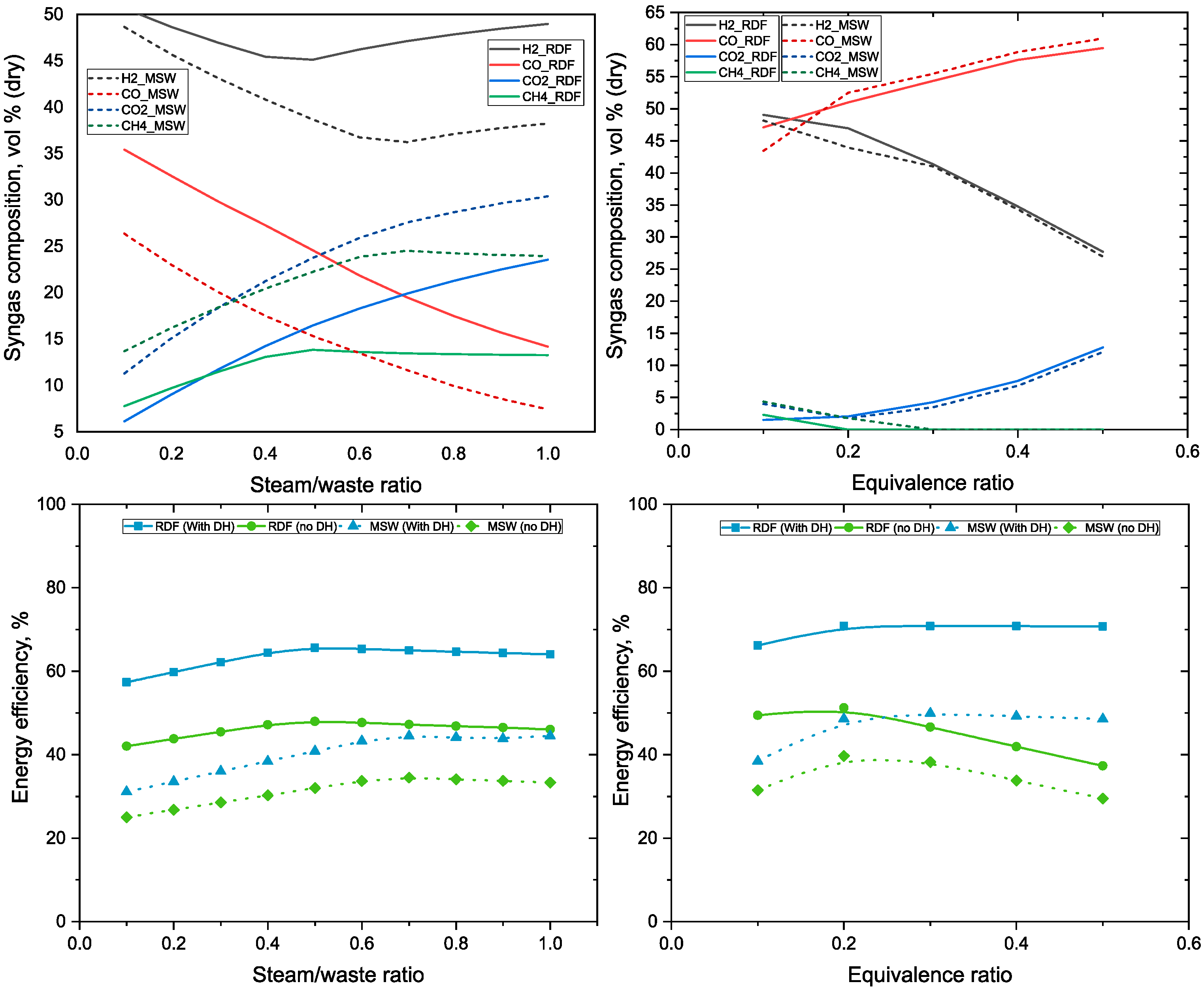
Figure 11 presents the effect of the steam/waste ratio and ER on the syngas volumetric composition and energy efficiency of the polygeneration process from the EFG. The steam/waste ratio is varied within the range of 0.1 to 1.0. The carbon monoxide volumetric percentage decreases, while the methane and carbon dioxide percentages increase with steam/waste ratio. MSW gasification produces syngas with lower carbon monoxide and hydrogen percentage than RDF gasification in the EFG. Change in the energy efficiency of the polygeneration facility with the steam/waste ratio is also estimated. Efficiency for RDF gasification is higher than for MSW gasification with the EFG because RDF has less moisture and higher elemental carbon and hydrogen content than MSW. The polygeneration process with DH also shows higher energy efficiency than the polygeneration process with no DH output. Energy efficiency increases up to a steam/waste ratio of 0.4, but changes only marginally with the further increase in steam in EFG.
The ER in the EFG is varied from 0.1 to 0.5, and its effect on syngas volumetric composition is presented in Figure 11. In the EFG, the volumetric percentages of carbon monoxide and carbon dioxide in syngas increase, while the percentages of hydrogen and methane decrease with increasing ER. The polygeneration efficiency increases up to an ER of 0.2, and then decreases with further increases in ER. Increases in ER in the EFG initially increase the energy efficiency, but then decrease the efficiency when DH is not considered as a product; the polygeneration efficiency does not increase when ER is at or above 0.2 for EFG with DH.
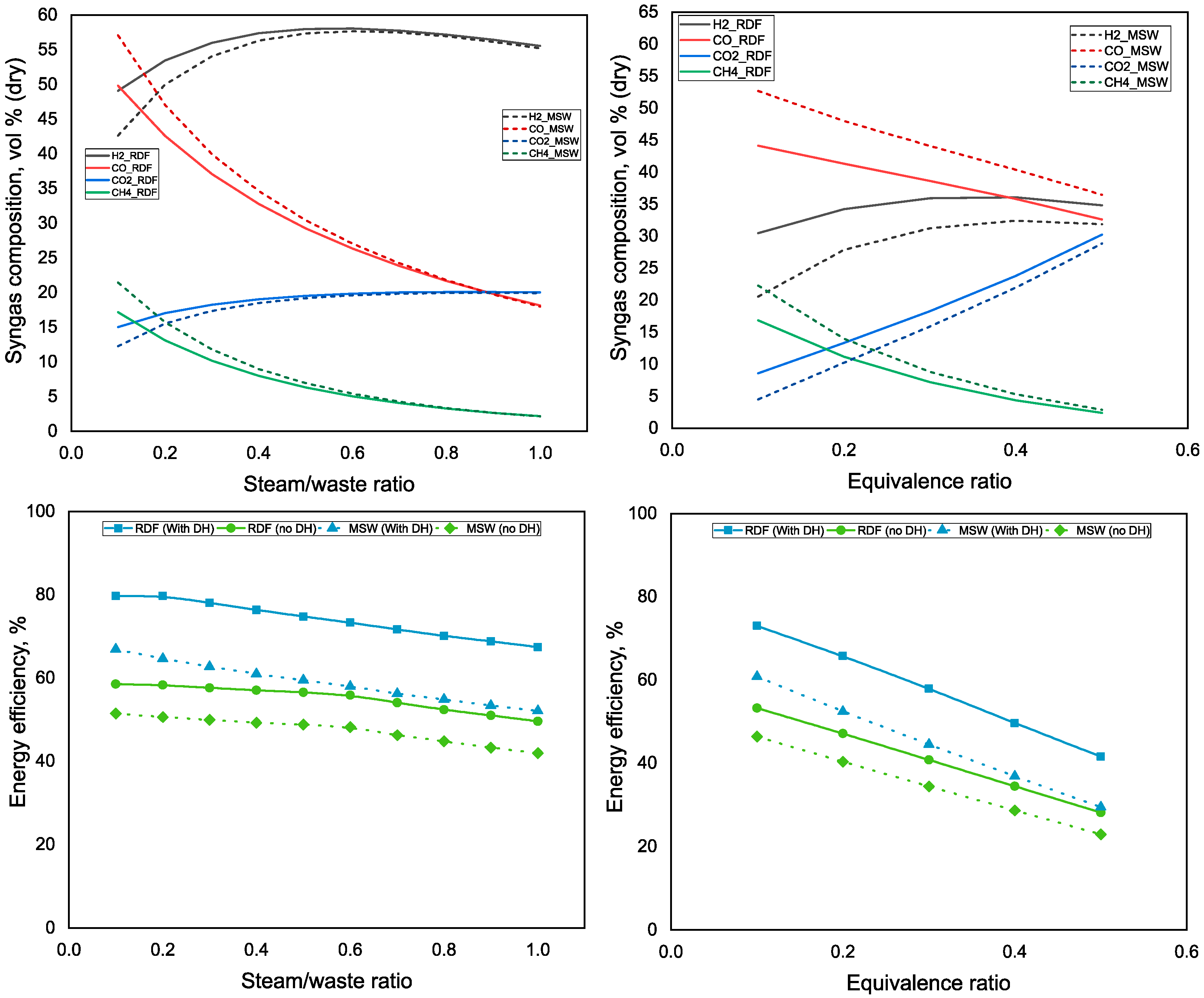
Figure 12 shows the effect of the steam/waste ratio and ER on the syngas volumetric composition and polygeneration energy efficiency from the CFBG. Similar to EFG, syngas from MSW gasification contains a lower percentage of hydrogen than RDF gasification for the CFBG. However, the carbon monoxide percentage in syngas from MSW gasification is higher than that from RDF gasification. The volumetric percentage of carbon monoxide and methane in syngas decrease with increasing steam/waste ratio, whereas the percentages of hydrogen and carbon dioxide increase. There is a marginal increase in polygeneration energy efficiency in the CFBG with a steam/waste ratio of up to 0.4, and efficiency decreases with further increases in steam content.
The carbon dioxide percentage in syngas increases with the increase in ER, whereas carbon monoxide and methane content of syngas decrease with ER in the CFBG. The increase in hydrogen percentage with ER in the CFBG is marginal. The energetic efficiency of the polygeneration process decreases with ER. Similar to the EFG, the energy efficiency of RDF gasification is higher than that of MSW gasification in CFBG.
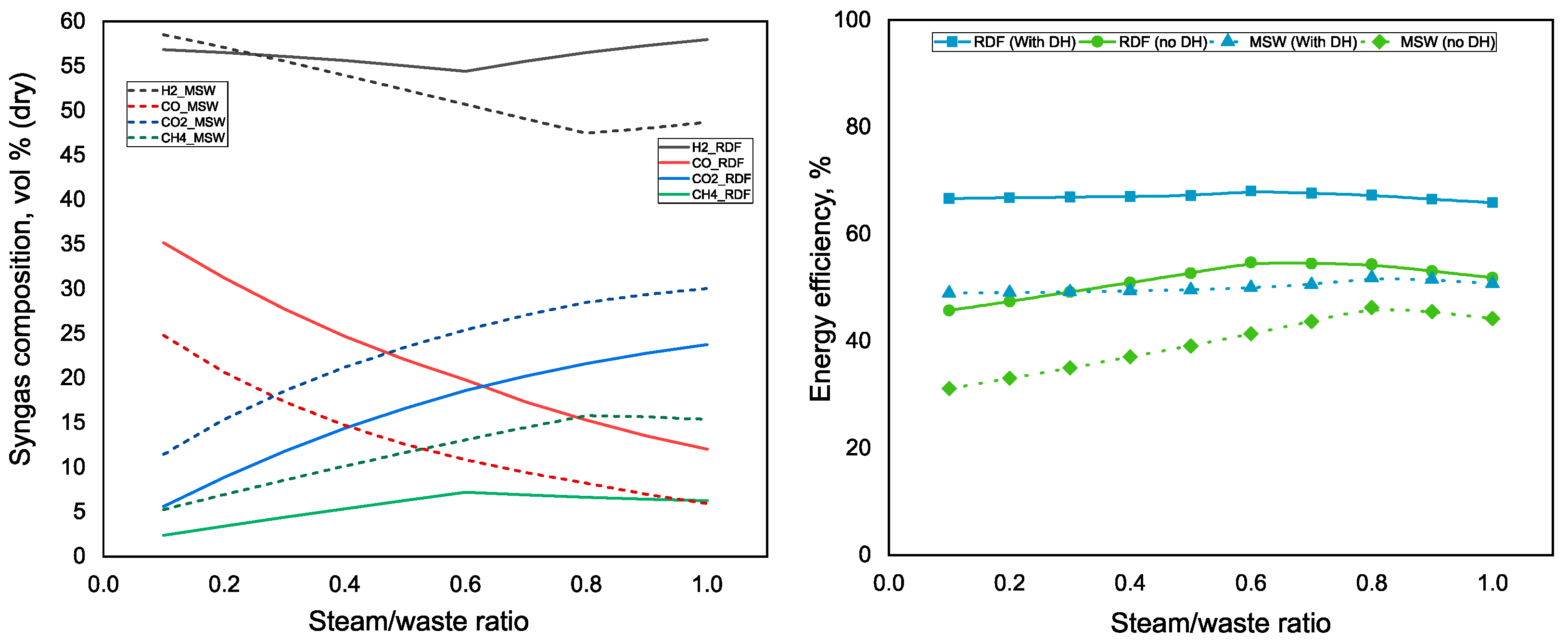
The effects of the steam/waste ratio on the syngas volumetric composition and polygeneration efficiency in the DFBG are shown in Figure 13. The volumetric percentage of carbon monoxide in syngas decreases with steam/waste ratio, whereas the percentages of carbon dioxide and methane increase with the steam/waste ratio in the DFBG. Carbon dioxide and methane percentages in syngas from MSW gasification are higher than those from RDF gasification in the DFBG. Hydrogen and carbon monoxide volumetric percentages are lower in syngas from MSW gasification than from RDF gasification in the case of DFBG. The energy efficiency of the polygeneration process with the DFBG increases with the steam/waste ratio for both MSW and RDF gasification, but the efficiency tends to decrease at very high steam-to-waste ratios.
Figure 11, Figure 12 and Figure 13 provide the optimum steam/waste ratio and ER for the polygeneration process. Table 2 shows the steam/waste ratio and ER selected for the further analysis of various polygeneration cases explained in Section 2.4 and syngas composition under these conditions. A steam/waste ratio of 0.3 was selected for the EFG, whereas for the CFBG and the DFBG a steam/waste ratio of 0.4 was considered. An ER of 0.2 was chosen for the EFG and 0.1 was selected for the CFBG. The syngas volumetric composition (dry) of these gasifiers for both RDF and MSW gasification is shown in Table 2. Syngas from the EFG and DFBG has higher hydrogen percentage than that from the CFBG. The EFG produces syngas with a higher volumetric percentage of carbon monoxide than the CFBG and DFBG. The methane percentage is negligible in syngas from the EFG, but higher in syngas from the CFBG and DFBG. Syngas from the DFBG and CFBG has higher carbon dioxide percentages than syngas from the EFG. The CGE of gasifiers is higher with RDF waste as feedstock than with MSW.
As described above, two different types of waste feedstock—RDF and MSW—were considered in this study. RDF and MSW have different moisture contents, elemental compositions and heating values. A 500 MW polygeneration plant was considered as a basis in this study. Different waste types and compositions would therefore change the amount of waste fed into the 500 MW polygeneration plant. Table 3 shows the mass flow rate of waste required in the 500 MW polygeneration plant for RDF, MSW and mixture of both types of feedstock. RDF contains less moisture and higher LHV than MSW, so less RDF is required than MSW. Similarly, when a mixture of RDF and MSW is fed into the polygeneration plant, the total amount is higher than for 100% RDF but lower than for 100% MSW.
Cases 1 to 4 for polygeneration plants (as described in Section 2.4) were simulated under the conditions presented in Table 2. The following sections present and discuss the simulation results for all polygeneration cases.

3.2. Case 1 Results

In case 1, a polygeneration facility of 500 MW was simulated. An equal amount of syngas generated was transferred to produce power and various biofuels (methane, methanol/DME, FT fuels and ammonia). The results are shown in Figure 14. The EFG produces more power than the CFBG and DFBG. Methane production from the CFBG and DFBG is higher than from the EFG. One reason for the higher methane production in the CFBG and DFBG is the higher methane content in the syngas from these gasifiers. The CFBG and DFBG produce similar amounts of methane biofuel from RDF, but the DFBG produces more methane biofuel than the CFBG from MSW. Ammonia production is higher in the DFBG than in the EFG and CFBG. Methanol/DME production in the CFBG and DFBG is higher than in the EFG, whereas FT diesel and FT gasoline production is similar for all gasifiers. The EFG shows the highest overall polygeneration efficiency when the low-temperature excess heat is utilized for DH, followed by the DFBG and the CFBG. The DFBG shows higher polygeneration efficiency when DH is not considered as an output. Overall, polygeneration efficiency for RDF gasification is higher than that for MSW gasification, mainly due to lower moisture and high carbon and hydrogen content.

3.3. Case 2 Results

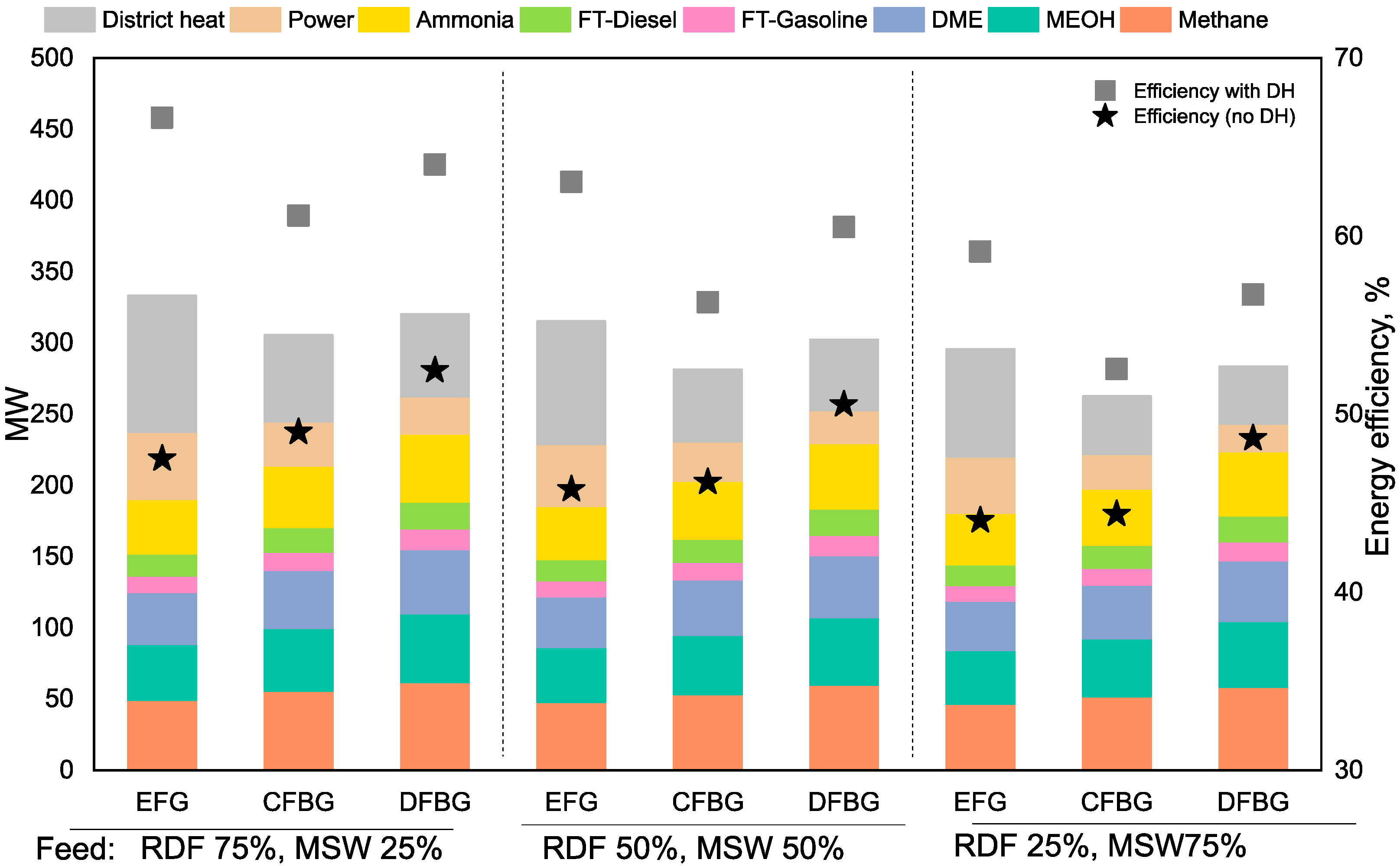
In case 2, polygeneration processes with feed comprising a mix of RDF and MSW were simulated. Three sub-cases with 75% RDF/25% MSW, 50% RDF/50% MSW, and 25% RDF/75% MSW were considered. Syngas generated from the mixed-feed gasification was transferred equally to produce power and various biofuels (methane, methanol/DME, FT fuels, and ammonia). Polygeneration efficiency with and without DH was also estimated. The results are shown in Figure 15. A large amount of power and DH is produced with mixed-feed gasification with 75% RDF/25% MSW fraction, whereas 25% RDF/75% MSW result in lower power output. Similarly, biofuels production also decreases with the increase in MSW content in mixed feed. The DFBG shows greater efficiency when only biofuels and power are produced, whereas the EFG shows higher efficiency when DH is also considered along with biofuels and power.

3.4. Case 3 Results

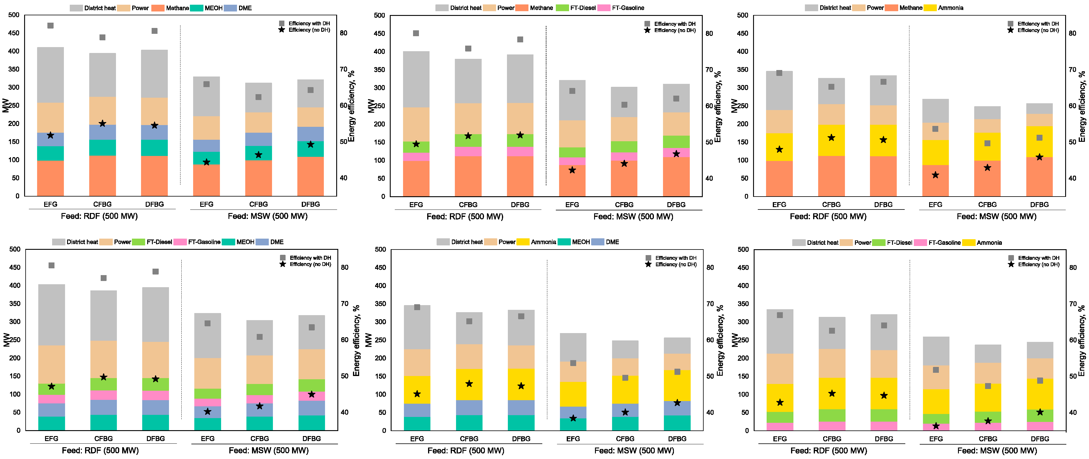
In case 3, the polygeneration plant produced only 2 or 3 biofuels along with DH and power. Six different subcases were simulated, as described in Figure 10 and Section 2.4. The results are presented in Figure 16. The waste polygeneration plant producing methane, methanol/DME, power and DH shows the highest energetic return, followed by the plant producing methane, FT fuels, power and DH, and the plant producing methane, ammonia, power and DH. Polygeneration plants with the CFBG or DFBG show higher energy efficiency than those with the EFG when no DH is considered. Polygeneration efficiencies are similar for all gasifiers when low-temperature waste heat is recovered as DH alongside power and biofuels production. The polygeneration efficiency reaches up to 80% in cases with DH, power, methane and methanol/DME, or DH, power, methane, and FT fuels with the EFG and DFBG.

3.5. Case 4 Results

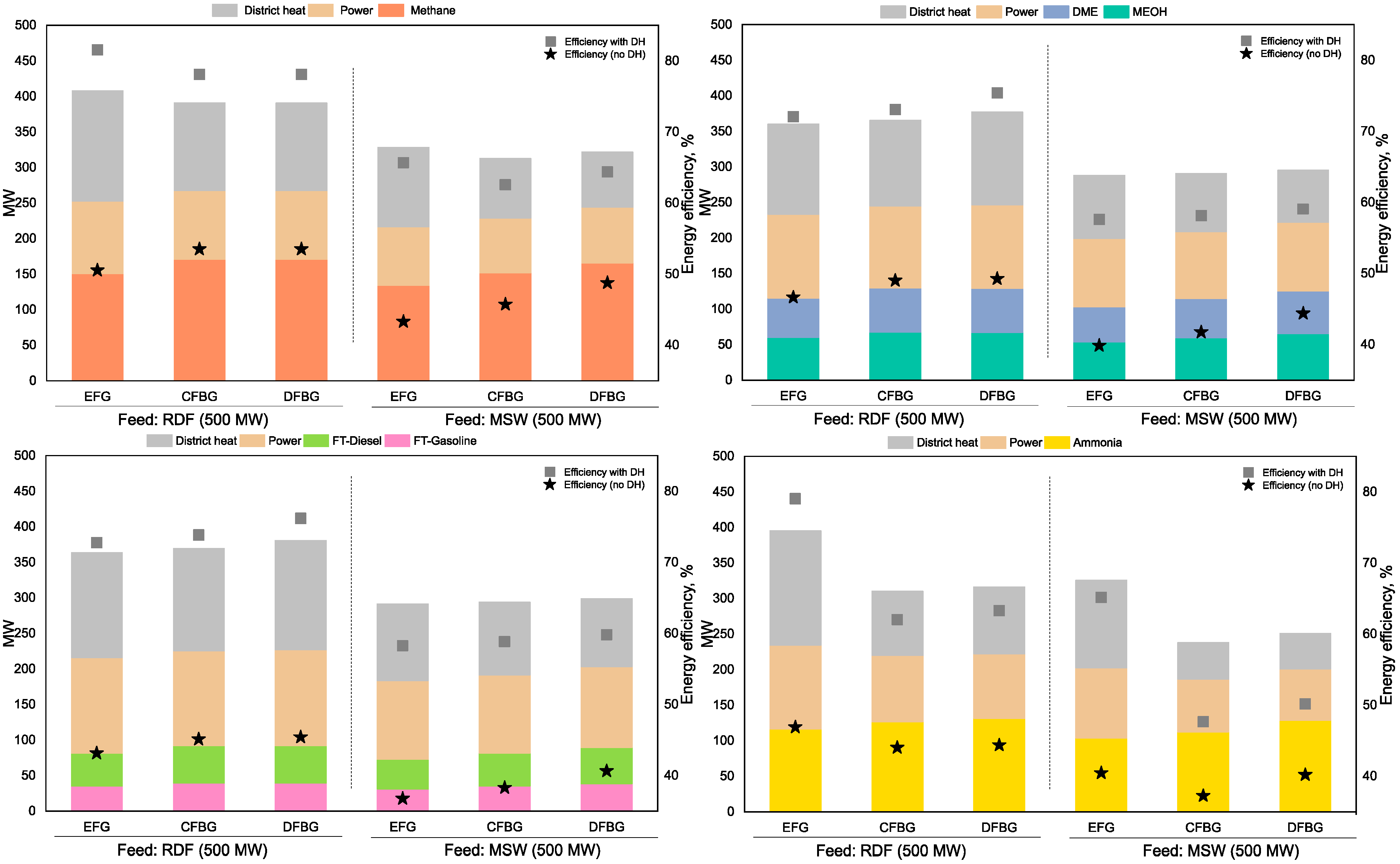
In this last case, the trigeneration plant with waste gasification was simulated. Figure 17 shows the simulation results. Trigeneration of methane with power and DH achieve the highest energy efficiency, followed by methanol/DME, ammonia and FT fuels with DH and power. The EFG shows efficient trigeneration of methane, DH and power, and ammonia, DH and power. The DFBG shows higher energy efficiency for the trigeneration of methanol, DH and power, and FT fuels, DH and power. When DH is not considered, the DFBG and CFBG show better performance than the EFG. Similar to cases 1–3, RDF shows better results than MSW when used for the gasification feed.

3.6. Carbon Dioxide Emissions

Table 4 shows the carbon dioxide emissions in tonne/MJ of waste feed for the gasifiers—EFG, CFBG and DFBG. RDF has higher cumulative carbon content than MSW; therefore, the polygeneration plant has higher specific carbon dioxide emissions with RDF as feedstock. Among the gasifiers, EFG and DFBG produce slightly higher carbon dioxide emissions than the CFBG.

4. Discussion

This section discusses some of the limitations of this study. The polygeneration processes studied in this paper are simulated through the commercially available software Aspen Plus. The modelling of waste gasification requires a set of assumptions, such as for syngas composition, which produced uncertainties in the results. In addition, the models for waste gasification were developed by considering equilibrium conditions due to a lack of information in the literature regarding the reaction kinetics for MSW and RDF gasification. Thus, the reliability of simulation results from gasification requires checking and validation. CGE was selected to compare the results in this study with the published literature. According to Meerman et al. [23], the CGE of gasification obtained from the model should be in line with the literature value of 79–83%. The CGE of gasification in our models is in the range of 79–84%, which is consistent with this reported range.
This study considers the properties of waste as constant for steady-state simulations, but waste is actually heterogeneous, and the properties of MSW and RDF vary in different regions and at different times of year, which alters the actual operation of the gasification process.
Gasification of waste and biomass also produces tar in syngas, which needs to be removed before further processing of syngas to biofuels. For simplicity, this study excludes tar production. Similarly, the removal of sulfur and carbon dioxide was not modelled.
Although the DFBG shows higher biofuel conversion efficiencies than the CFBG and EFG, it requires two reactors, which may increase the required capital and operating costs. However, the EFG and CFBG require an ASU to produce nitrogen-free syngas, which increases their capital expenses.
The EFG requires liquid feedstock (such as black liquor) or very fine-sized feed. For biomass-based feedstock, Meijdan et al. [33] recommend torrefaction as a pretreatment before the EFG. This study considered only grinding and crushing of waste to less than 2 mm as a pretreatment. However, the use of torrefaction as a pretreatment may also increase the capital and operating expenses.
The study used gasification of MSW and RDF as a base thermochemical process for the polygeneration of biofuels, DH and power; however, pyrolysis of waste is an alternative thermochemical process that can convert waste into biofuels, heat and power.
Polygeneration systems comprise a complex set of multiple processes for the synthesis of biofuels alongside heat and power. The demand for bioenergy products is dependent on local conditions and demand, e.g., DH is not a potential product in countries with a warm climate. Similarly, the production of biofuels is dependent on the energy mix of the country. Thus, the primary aim of the study was to perform a system analysis of waste-based polygeneration plants and report optimum conditions and gasifier reactors for waste conversion to energy. Further optimization with specific country and regional case studies and economic analyses will be the next step towards waste gasification-based polygeneration processes.

5. Conclusions

This study provides the process-modelling framework for waste gasification-based flexible polygeneration facilities for the production of heat, power and various biofuels. The technical performance was analyzed for three different gasifiers—the EFG, the CFBG and the DFBG. Various combinations of products were assessed through different case studies. The main conclusions are as follows.
The properties of waste are critical for their conversion into useful bioproducts. Waste with high moisture and ash content (such as MSW) require a significant amount of energy for preprocessing such as drying and grinding. The lower carbon and hydrogen content of MSW also decreases the overall efficiency of the polygeneration process. Processing of MSW into RDF significantly improves the system technical performance, as RDF has lower moisture and ash content as well as higher carbon and hydrogen content and high LHV.
In terms of waste gasification, the steam/waste ratio and ER is decisive for the production of syngas with high heating value. Different gasifiers have different optimum conditions for producing high-quality syngas. The EFG shows the best energetic performance when DH is also produced in the polygeneration process alongside power and biofuels. The DFBG and CFBG show better polygeneration efficiency when only power and biofuels are produced. The polygeneration process with 2 or 3 biofuels alongside DH and power shows better overall performance than the polygeneration process with 5 biofuels, DH and power.
Overall, modelling and simulation results from waste polygeneration processes show that this is a promising option for treating and reducing MSW. However, further analyses, such as the economic potential of the polygeneration process, uncertainty analysis and determination of optimum products, will provide a clearer picture of waste-based polygeneration systems.
Furthermore, the financial implications of these polygeneration facilities to treat waste must be studied and compared for different regions and scenarios. The flexibility of these processes in terms of full- and part-load operation must also be assessed in future work.

Author Contributions

Both authors contributed equally to the manuscript. Conceptualization, C.A.S. and C.B.O.; Data curation, C.B.O.; Formal analysis, C.B.O.; Methodology, C.A.S.; Software, C.A.S.; Visualization, C.A.S. and C.B.O.; Writing—original draft, C.A.S and C.B.O. All authors have read and agreed to the published version of the manuscript.

Funding

This work was supported by the Swedish Knowledge Foundation (20120276) (KKS) and the co-production partners within the framework Future Energy: ABB, Castellum and the VEMM group (VafabMiljö, Eskilstuna Energi och Miljö, and Mälarenergi). Bilal Omer also want to acknowledge support from KAPCO for data used in this study.

Conflicts of Interest

The authors declare no conflict of interest.

Nomenclature

AGRAcid gas removal
ASFAnderson–Schultz–Flory
ASUAir separation unit
CFBGCirculating fluidized bed gasifier
CGECold gas efficiency
DFBGDual fluidized bed gasifier
DHDistrict heating
DMEDimethyl ether
DSTWUShortcut distillation column block in Aspen Plus
EFGEntrained flow gasifier
EREquivalence ratio
FTFischer Tropsch
HHVHigher heating value
HPHigh pressure
HRSGHeat recovery steam generation
LHVLower heating value
LPLow pressure
MDEAN-methyl diethanolamine
MPMedium pressure
MSWMunicipal solid waste
PSAPressure swing adsorption
RDFRefuse derived fuel
REQUILAspen Plus reactor block based on equilibrium reactions
RGIBBSAspen Plus reactor block based on minimizing Gibbs energy
RSTOICHAspen Plus reactor block based on known stoichiometric reactions
RYIELDAspen Plus reactor block based on component yields
WGSWater–gas shift

References

  1. Bhaskar, T.; Pandey, A.; Rene, E.; Tsang, D. Waste Biorefinery Integrating Biorefineries for Waste Valorisation; Elsevier: Amsterdam, The Netherlands, 2020; Volume 53. [Google Scholar] [CrossRef]
  2. Istrate, I.-R.; Iribarren, D.; Galvez-Martos, J.; Dufour, J. Review of life-cycle environmental consequences of waste-to-energy solutions on the municipal solid waste management system. Resour. Conserv. Recycl. 2020, 157, 104778. [Google Scholar] [CrossRef]
  3. Moharir, R.V.; Gautam, P.; Kumar, S. Waste Treatment Processes/Technologies for Energy Recovery. In Current Developments in Biotechnology and Bioengineering; Elsevier: Amsterdam, The Netherlands, 2019; pp. 53–77. [Google Scholar] [CrossRef]
  4. Giugliano, M.; Ranzi, E. Thermal Treatments of Waste. In Waste to Energy (WtE); Elsevier Inc.: Amsterdam, The Netherlands, 2016. [Google Scholar] [CrossRef]
  5. Chen, H.; Jiang, W.; Yang, Y.; Yang, Y.; Man, X. Global trends of municipal solid waste research from 1997 to 2014 using bibliometric analysis. J. Air Waste Manag. Assoc. 2015, 65, 1161–1170. [Google Scholar] [CrossRef] [PubMed] [Green Version]
  6. Miandad, R.; Rehan, M.; Barakat, M.A.; Aburiazaiza, A.S.; Khan, H.; Ismail, I.M.I.; Dhavamani, J.; Gardy, J.; Hassanpour, A.; Nizami, A.-S. Catalytic Pyrolysis of Plastic Waste: Moving Toward Pyrolysis Based Biorefineries. Front. Energy Res. 2019, 7, 1–17. [Google Scholar] [CrossRef] [Green Version]
  7. Bioenergy IEA. Gasification of Waste for Energy Carriers; IEA: Paris, France, 2018. [Google Scholar]
  8. Whiting, K.; Wood, S.; Fanning, M. Waste Technologies: Waste to Energy Facilities—A Report for the Strategic Waste Infrastructure Planning (SWIP) Working Group. Available online: http://large.stanford.edu/courses/2017/ph240/kim-d2/docs/wsp-may13.pdf (accessed on 5 July 2020).
  9. Segurado, R.; Pereira, S.; Correia, D.; Costa, M. Techno-economic analysis of a trigeneration system based on biomass gasification. Renew. Sustain. Energy Rev. 2019, 103, 501–514. [Google Scholar] [CrossRef]
  10. Jana, K.; Ray, A.; Majoumerd, M.M.; Assadi, M.; De, S. Polygeneration as a future sustainable energy solution—A comprehensive review. Appl. Energy 2017, 202, 88–111. [Google Scholar] [CrossRef]
  11. Ciuta, S.; Tsiamis, D.; Castaldi, M.J. Gasif Waste Mater Technol Gener Energy, Gas, Chem from Munic Solid Waste, Biomass, Nonrecycled Plast Sludges, Wet Solid Wastes. In Critical Development Needs; Elsevier: Amsterdam, The Netherlands, 2017; pp. 121–141. [Google Scholar] [CrossRef]
  12. Gootz, M.; Forman, C.; Wolfersdorf, C.; Meyer, B. Polygeneration-Annex: Combining lignite-based power generation and syngas-based chemicals production. Fuel 2017, 203, 989–996. [Google Scholar] [CrossRef]
  13. Buttler, A.; Kunze, C.; Spliethoff, H. IGCC–EPI: Decentralized concept of a highly load-flexible IGCC power plant for excess power integration. Appl. Energy 2013, 104, 869–879. [Google Scholar] [CrossRef]
  14. Yu, G.-W.; Xu, Y.-Y.; Hao, X.; Li, Y.-W.; Liu, G.-Q. Process analysis for polygeneration of Fischer–Tropsch liquids and power with CO2 capture based on coal gasification. Fuel 2010, 89, 1070–1076. [Google Scholar] [CrossRef]
  15. Narvaez, A.; Chadwick, D.; Kershenbaum, L. Small-medium scale polygeneration systems: Methanol and power production. Appl. Energy 2014, 113, 1109–1117. [Google Scholar] [CrossRef]
  16. Li, Y.; Zhang, G.; Yang, Y.; Zhai, D.; Zhang, K.; Xu, G. Thermodynamic analysis of a coal-based polygeneration system with partial gasification. Energy 2014, 72, 201–214. [Google Scholar] [CrossRef]
  17. Guo, Z.; Wang, Q.; Fang, M.; Luo, Z.; Cen, K. Thermodynamic and economic analysis of polygeneration system integrating atmospheric pressure coal pyrolysis technology with circulating fluidized bed power plant. Appl. Energy 2014, 113, 1301–1314. [Google Scholar] [CrossRef]
  18. Li, M.; Zhuang, Y.; Zhang, L.; Liu, L.; Du, J.; Shen, S. Conceptual design and techno-economic analysis for a coal-to-SNG/methanol polygeneration process in series and parallel reactors with integration of waste heat recovery. Energy Convers. Manag. 2020, 214, 112890. [Google Scholar] [CrossRef]
  19. Huang, H.; Yang, S.; Cui, P. Design concept for coal-based polygeneration processes of chemicals and power with the lowest energy consumption for CO2 capture. Energy Convers. Manag. 2018, 157, 186–194. [Google Scholar] [CrossRef]
  20. Heinze, C.; May, J.; Peters, J.; Ströhle, J.; Epple, B. Techno-economic assessment of polygeneration based on fluidized bed gasification. Fuel 2019, 250, 285–291. [Google Scholar] [CrossRef]
  21. Kim, S.; Kim, M.; Kim, Y.T.; Kwak, G.; Kim, J. Techno-economic evaluation of the integrated polygeneration system of methanol, power and heat production from coke oven gas. Energy Convers. Manag. 2019, 182, 240–250. [Google Scholar] [CrossRef]
  22. Fan, J.; Hong, H.; Jin, H. Biomass and coal co-feed power and SNG polygeneration with chemical looping combustion to reduce carbon footprint for sustainable energy development: Process simulation and thermodynamic assessment. Renew. Energy 2018, 125, 260–269. [Google Scholar] [CrossRef]
  23. Meerman, H.; Ramírez, A.; Turkenburg, W.; Faaij, A. Performance of simulated flexible integrated gasification polygeneration facilities. Part A: A technical-energetic assessment. Renew. Sustain. Energy Rev. 2011, 15, 2563–2587. [Google Scholar] [CrossRef]
  24. Sahoo, U.; Kumar, R.; Pant, P.; Chaudhary, R. Development of an innovative polygeneration process in hybrid solar-biomass system for combined power, cooling and desalination. Appl. Therm. Eng. 2017, 120, 560–567. [Google Scholar] [CrossRef]
  25. Jana, K.; De, S. Polygeneration using agricultural waste: Thermodynamic and economic feasibility study. Renew. Energy 2015, 74, 648–660. [Google Scholar] [CrossRef]
  26. Jana, K.; De, S. Sustainable polygeneration design and assessment through combined thermodynamic, economic and environmental analysis. Energy 2015, 91, 540–555. [Google Scholar] [CrossRef]
  27. Gładysz, P.; Saari, J.; Czarnowska, L. Thermo-ecological cost analysis of cogeneration and polygeneration energy systems—Case study for thermal conversion of biomass. Renew. Energy 2020, 145, 1748–1760. [Google Scholar] [CrossRef]
  28. Villarroel-Schneider, J.; Mainali, B.; Martí-Herrero, J.; Malmquist, A.; Martin, A.; Alejo, L. Biogas based polygeneration plant options utilizing dairy farms waste: A Bolivian case. Sustain. Energy Technol. Assess. 2020, 37, 100571. [Google Scholar] [CrossRef]
  29. Jana, K.; De, S. Environmental impact of an agro-waste based polygeneration without and with CO2 storage: Life cycle assessment approach. Bioresour. Technol. 2016, 216, 931–940. [Google Scholar] [CrossRef] [PubMed]
  30. De La Fuente, E.; Martín, M. Optimal CSP-Waste Based Polygeneration Coupling for Constant Power Production; Elsevier BV: Amsterdam, The Netherlands, 2019; Volume 46, pp. 1645–1650. [Google Scholar]
  31. McKendry, P. Energy production from biomass (Part 2): Conversion technologies. Bioresour. Technol. 2002, 83, 47–54. [Google Scholar] [CrossRef]
  32. Heyne, S.; Thunman, H.; Harvey, S. Exergy-based comparison of indirect and direct biomass gasification technologies within the framework of bio-SNG production. Biomass Convers. Biorefin. 2013, 3, 337–352. [Google Scholar] [CrossRef] [Green Version]
  33. Van Der Meijden, C.M.; Veringa, H.J.; Rabou, L.P. The production of synthetic natural gas (SNG): A comparison of three wood gasification systems for energy balance and overall efficiency. Biomass Bioenergy 2010, 34, 302–311. [Google Scholar] [CrossRef]
  34. Gassner, M.; Wang, L. Thermo-economic process model for thermochemical production of Synthetic Natural Gas (SNG) from lignocellulosic biomass. Biomass Bioenergy 2009, 33, 1587–1604. [Google Scholar] [CrossRef] [Green Version]
  35. Tungalag, A.; Lee, B.; Yadav, M.; Akande, O. Yield prediction of MSW gasification including minor species through ASPEN plus simulation. Energy 2020, 198, 117296. [Google Scholar] [CrossRef]
  36. Buckley, T.J. Calculation of higher heating values of biomass materials and waste components from elemental analyses. Resour. Conserv. Recycl. 1991, 5, 329–341. [Google Scholar] [CrossRef]
  37. Özyuğuran, A.; Yaman, S.; Küçükbayrak, S. Prediction of calorific value of biomass based on elemental analysis. Int. Adv. Res. Eng. J. 2018, 2, 254–260. [Google Scholar]
  38. Aspen Technology, Inc. Aspen Plus. USA. 2020. Available online: https://www.aspentech.com/ (accessed on 25 March 2020).
  39. Aspentech. Getting Started Modeling Processes with Solids; Aspen Technology: Burlington, VT, USA, 2013. [Google Scholar]
  40. Salman, C.A. Techno Economic Analysis of Wood Pyrolysis in Sweden; KTH Stockholm: Stockholm, Sweden, 2014. [Google Scholar]
  41. Harris, D.; Roberts, D. Coal Gasification and Conversion; Elsevier BV: Amsterdam, The Netherlands, 2013; Volume 2, pp. 427–454. [Google Scholar]
  42. Li, K.; Cousins, A.; Yu, H.; Feron, P.H.; Tade, M.; Luo, W.; Chen, J. Systematic study of aqueous monoethanolamine-based CO2 capture process: Model development and process improvement. Energy Sci. Eng. 2015, 4, 23–39. [Google Scholar] [CrossRef] [Green Version]
  43. Heyne, S.; Thunman, H.; Harvey, S. Extending existing combined heat and power plants for synthetic natural gas production. Int. J. Energy Res. 2011, 36, 670–681. [Google Scholar] [CrossRef] [Green Version]
  44. Clausen, L.R.; Elmegaard, B.; Ahrenfeldt, J.; Henriksen, U.B. Thermodynamic analysis of small-scale dimethyl ether (DME) and methanol plants based on the efficient two-stage gasifier. Energy 2011, 36, 5805–5814. [Google Scholar] [CrossRef] [Green Version]
  45. Pondini, M.; Ebert, M. Process Synthesis and Design of Low Temperature Fischer-Tropsch Crude Production from Biomass Derived Syngas. Master’s Thesis, Chalmers University of Technology, Göteborg, Sweden, 2013. [Google Scholar]
  46. Song, H.-S.; Ramkrishna, R.; Trinh, S.; Wright, H. Operating strategies for Fischer-Tropsch reactors: A model-directed study. Korean J. Chem. Eng. 2004, 21, 308–317. [Google Scholar] [CrossRef]
Figure 1. Simplified process flow diagram of a waste-based polygeneration facility. Two types of feed—RDF and MSW—are considered and three different gasifiers—EFG, CFBG, and DFBG—are evaluated.
Energies 13 04264 g001
Figure 2. Process flow diagram of entrained flow gasification of MSW and RDF.
Energies 13 04264 g002
Figure 3. Process flow diagram of gasification of MSW and RDF in the directly heated CFBG.
Energies 13 04264 g003
Figure 4. Process flow diagram of gasification of MSW and RDF in the indirectly heated DFBG.
Energies 13 04264 g004
Figure 5. Process flow diagram of methane synthesis from syngas produced from waste gasification.
Energies 13 04264 g005
Figure 6. Process flow diagram of methanol and DME synthesis from syngas produced from waste gasification.
Energies 13 04264 g006
Figure 7. Process flow diagram of FT diesel and FT gasoline synthesis from syngas produced from waste gasification.
Energies 13 04264 g007
Figure 8. Process flow diagram of ammonia synthesis from syngas produced from waste gasification.
Energies 13 04264 g008
Figure 9. Process flow diagram of power and heat produced from combustion of syngas produced from waste gasification.
Energies 13 04264 g009
Figure 10. Description of waste to energy polygeneration cases simulated in this study.
Energies 13 04264 g010
Figure 11. Effect of the steam-to-waste ratio and ER on syngas composition and biofuel synthesis from the EFG.
Energies 13 04264 g011
Figure 12. Effect of the steam-to-waste ratio and ER on syngas composition and biofuel synthesis from the CFBG.
Energies 13 04264 g012
Figure 13. Effect of the steam-to-waste ratio on syngas composition and biofuel synthesis from the DFBG.
Energies 13 04264 g013
Figure 14. Power, biofuels and heat distribution from RDF and MSW gasification in three gasifiers (EFG, CFBG; and DFBG). Feed = 500 MW; an equal amount of syngas was transferred for biofuels and power production in each case.
Energies 13 04264 g014
Figure 15. Power, biofuels and heat distribution for gasification of mixed RDF and MSW feed in the three gasifiers (EFG, CFBG and DFBG). Total feed = 500 MW; an equal amount of syngas was transferred for biofuels and power production in each case.
Energies 13 04264 g015
Figure 16. Polygeneration of power, heat and two biofuels from RDF and MSW gasification in the three gasifiers (EFG, CFBG and DFBG). Total feed = 500 MW; an equal amount of syngas was transferred for the production of power and the two biofuels in each case.
Energies 13 04264 g016
Figure 17. Trigeneration of power, heat and biofuel from RDF and MSW gasification in the three gasifiers (EFG, CFBG and DFBG). Total feed = 500 MW; an equal amount of syngas was transferred for the production of power and two biofuels in each case.
Energies 13 04264 g017
Table 1. Ultimate and proximate analyses of RDF and MSW (wt%) [7,35].
RDFMSW
Carbon52.1158.45
Hydrogen7.406.87
Nitrogen0.851.36
Sulfur0.462.49
Chlorine0.070.30
Oxygen39.1130.53
Ash17.4730.81
Moisture13.1251.87
Note: C, H, N, S, Cl, O are presented on a dry and ash-free basis; ash is on a dry basis.
Table 2. Volumetric composition of syngas from gasifiers (the EFG, CFBG and DFBG) for both MSW and RDF gasification selected for heat, power and biofuel synthesis in polygeneration cases 1 to 4.
FeedstockEFGCFBGDFBG
RDFMSWRDFMSWRDFMSW
Steam/waste ratio0.30.30.40.40.40.4
ER0.20.20.10.1--
H2, %54.349.742.440.555.654
CO, %40.041.433.835.024.714.7
CO2, %5.78.913.516.214.421.2
CH4, %negligiblenegligible10.38.35.310.1
LHV, MJ/kg16.414.216.214.116.515.2
CGE, %84.480.283.379.484.978.4
Note: Syngas composition is on a volumetric and dry basis.
Table 3. Mass flow rate of waste (kg/s) required for a 500 MW polygeneration plant for different types and composition of wastes.
RDF, %MSW, %Mass Flow of Waste Equivalent to 500 MW, kg/s
100023.25
010040.88
752526
505029.6
257534.4
Table 4. CO2 emissions as t/MJ of feed with different gasifiers for a 500 MW polygeneration plant.
FeedCO2 Emissions, Tonne/MJ Feed
EFGCFBGDFBG
RDF37.3835.5237.06
MSW31.631.231.2