1. Introduction
By the end of 2019, the proportion of coal-fired installed capacity will still account for 55% of the power structure [
1]. Under the situation of abundant coal and tight electric power in China, thermal power generation is still the most important power generation mode in China. To improve the boiler efficiency is the inevitable choice for China’s coal-fired power plants [
2]. After decades of development, the unit parameters have been improved from subcritical to supercritical, and the efficiency has been increased from 30% to 47% [
3]. Therefore, the double reheat technology has become one of the most effective ways to improve the efficiency of coal-fired power plants [
4]. Many scholars have made great achievements in economy and key technologies [
5,
6,
7]. By increasing the pressure of superheated steam and the temperature of reheated steam, the double reheat technology increases the cycle efficiency and the thermal efficiency of the unit. It reduces the coal consumption of the unit, improves the thermal economy, and reduces the emission of pollutants. Similarly, it can improve the operating conditions of the last stage blade and make the unit safer. However, the use of double reheat technology makes the composition of the thermal system more complex, the investment cost increases, and the requirements for operation are higher [
8]. Since each temperature parameter is close to the limit value of the pipeline, a small temperature deviation will lead to serious consequences [
9]. Therefore, the steam temperature regulation of the reheat unit is the key to the safe and efficient operation of the unit.
In the steam side, the regulation mode is mainly spray cooling, but this way will reduce the work share of the high-pressure cylinder and reduce the overall cycle thermal efficiency of the unit, so it is not suitable for normal temperature regulation. However, this method is more sensitive and generally used as a fine adjustment measure [
10]. Flue gas side temperature regulation mainly includes FGR, burner swing, and flue gas damper. The swing of the burner has a certain effect on steam temperature regulation, but its long-term operation at a non-zero position will be affected by the flue gas vortex. Therefore, burner swing mode is not used in normal operation. The main method to adjust the outlet steam deviation is the flue gas baffle. Because the FGR system is relatively simple and has a wide range of reheat steam temperature regulation, flue gas recirculation is still the temperature regulation method of double reheat unit. However, the FGR will lead to the mismatch between the flue gas volume and the air volume, resulting in the decrease of unit efficiency. Therefore, the waste heat utilization technology must be adopted to reduce its adverse effects.
The low-temperature economizer is arranged in the tail flue, but its economic benefit is not high due to the limitation of flue gas temperature and heat transfer requirements. More studies show that increasing the air supply temperature of air preheater (APH) or arranging bypass flue (BPF) beside the APH to heat condensate can effectively reduce the exhaust gas temperature and improve the system efficiency [
11,
12,
13,
14]. Ma et al. took 660 MW thermal power plant as an example and analyzed the thermal performance and technical economy of three typical waste heat utilization processes, namely, low-temperature economizer, upwind section preheating, and BPF thermal system. The results showed that the BPF thermal system performed best [
15]. Ma Guoqian et al. [
16] added and analyzed the inlet temperature system of the APH heated by flue gas waste heat on the basis of BPF. The results showed that the thermal economy of the system was significantly improved through this advanced flue gas waste heat utilization system. At present, many documents prove that the two kinds of flue gas waste heat utilization systems, BPF and flue gas waste heat heating APH inlet air, have high economy and will be widely used in China [
17,
18].
FGR is to reintroduce the cold flue gas from the tail flue into the furnace, reduce the radiation in the furnace, change the temperature distribution in the boiler, and then adjust the heat transfer ratio [
19]. Many scholars have deeply studied the influence of FGR on boiler system. The results show that FGR can effectively reduce the generation of nitrogen oxides and improve boiler efficiency [
20,
21]. So far, the research on FGR can be roughly divided into the following two categories.
One is to explore the change of boiler system by changing different FGR rates. Hu, Pei et al. [
22,
23] applied FGR to oxycoal combustion, and found that the nitrogen oxide content in the flue gas decreased significantly. Byeonghun et al. [
24] conducted experiments with gas-fired boilers of laboratory scale and found that when FGR increased under the same air equivalent, the phenomenon of red heat on the burner surface decreased significantly, which confirmed the advantages of FGR in improving the safe operation of the unit. Liu et al. [
25] conducted quantitative analysis on the performance of incinerator HRSG under different FGR through experimental research. The results showed that with the increase of FGR, the boiler efficiency slightly increased, and NOx emission greatly reduced. V.T. Sidorkin et al. [
26] reached the same conclusion after introducing the circulating flue gas into the burner. In addition, through the simulation calculation combined with the experimental results, it can be more persuasive to demonstrate the impact of FGR on the boiler system, and also can eliminate some uncontrollable factors, making the theoretical results more accurate. Wang et al. [
27] explored the impact of FGR on denitrification and coal consumption rate through a numerical research method, indicating that FGR has obvious environmental and economic benefits. Li et al. [
28] used Aspen Plus simulation software to simulate the combustion process of coal biomass boiler and draw the conclusion that more than 10% FGR rate can basically offset NOx emission. Zhang et al. [
29] determined, based on the simulation, that the optimal FGR rate is obtained by thermal calculation, and high FGR rate is proposed under low load.
The second is to analyze the influence of different FGR location on the unit. Liu et al. [
9,
30] carried out numerical analysis and research on the combustion process of 1000 MW SUC; they also compared the NOx emission and the temperature distribution of steam water side and flue gas side of different FGR introduction positions. The results show that the introduction of FGR at the top of the burner is an effective method to control NOx generation and steam temperature, and also ensures the safe operation of the unit. Ehsan Houshfar et al. [
31] studied the influence of FGR’s introduction position on NOx production using a grate combustion reactor of laboratory scale and concluded that FGR can further reduce NOx emission on the basis of staged combustion. However, Ling et al. [
32] studied the influence of three different FGR introduction positions on industrial furnaces, and found that FGR can reduce NOx emissions, but slightly increase CO emissions. In fact, gas in the cycle technology is not only used in power plants, but also plays a positive role in other thermal cycle processes [
33,
34,
35,
36].
On the basis of the above literature review, we found that in the past research, most of the mathematicians used the FGR as the research variable, or adjusted its recirculation position, or adjusted its recirculation flow, to explore the trend of the change of different parameters of the boiler system. However, there are few papers to explore the change of FGR rate under different working conditions on the premise of ensuring the safe operation of the unit. In this paper, the simulation software is used to simulate the operation under different working conditions to get the change trend of FGR rate, which fills this gap. Under the safe operation of the unit, the temperature change of the intermediate point will lead to the new temperature characteristics of the steam temperature parameters in the boiler. Therefore, this paper first discusses the influence of intermediate temperature change on FGR under the control of main steam temperature. Then the load, coal quality, excess air factor, and feed water temperature are changed under the control of the intermediate point temperature, and the FGR rate is adjusted to ensure that the main steam temperature remains unchanged, so as to study the change trend of the FGR rate under different working conditions after changing the above parameters. Through the qualitative analysis of the steam control equation, as well as the quantitative analysis of the simulation, the causes of the inflection point under the change of the FGR rate are deeply explored. Finally, the change trend of the FGR rate in the flue gas residual heat utilization system is analyzed. The purpose of this paper is to analyze and understand the change of FGR rate with the change of working conditions to provide practical basis for the adjustment and optimization of boiler parameters, and to provide a reference for the study of system economy.
2. Thermal System Simulation
2.1. Equipment Description
In this paper, a super-supercritical reheat system is taken as the research object. EBSILON software is used to simulate the model of boiler system, steam turbine system, and boiler steam turbine coupled whole plant thermal system.
The boiler used in the boiler model is a 1000 MW single furnace, tower type arrangement, two-stage air supply, and four-corner tangential firing super-supercritical once-through boiler. The furnace of the boiler is composed of a spiral coil water wall and vertical membrane water wall, and the pulverizing system adopts a positive pressure direct blowing type. The superheated steam temperature is regulated by water coal ratio and water spray desuperheating. The reheated steam adopts flue gas baffle and flue gas recycling. The design coal quality of the boiler is bituminous coal. The common coal quality of boiler is shown in
Table 1.
The heating surfaces at all levels in the boiler are arranged on the upper part of the once-through tower furnace, surrounded by vertical water walls, and the lower part is spiral water walls. The layout of the heating surfaces is shown in
Figure 1.
Steam water side process: The feed water first enters the two-stage economizer for heating. After heating, it enters the lower part of the boiler through the downcomer, then enters the mixing header of the water wall through the ash hopper and the spiral water wall, and then enters the vertical water wall of the upper part of the boiler. Finally, it enters the steam separator after passing through the lead-in pipe. The water separated from the steam water separator enters the water storage tank, and this part of water will be pumped into the economizer through the recycling pump at the start-up stage. The steam separated from the steam water separator enters the primary superheater arranged at the bottom through the hanging pipe of the heating surface, then enters the secondary superheater after passing through the primary desuperheater, and then enters the tertiary superheater after passing through the secondary desuperheater. Finally, the main steam is delivered to the turbine system through the main steam channel. The exhaust steam from the ultra-high-pressure cylinder (UHP) of the steam turbine system enters into the high-pressure and low-temperature reheater and high-pressure and high-temperature reheater of the boiler system in turn for heating, and then it is delivered back to the high-pressure cylinder of the steam turbine to complete the primary reheating process of the whole system. The exhaust gas from the high-pressure cylinder continues to return to the low-pressure and low-temperature reheater and the low-pressure and high-temperature reheater of the boiler system in turn for heating, and then it passes through the secondary heating after the reheat pipeline is delivered to the intermediate pressure cylinder to continue to work and complete the second reheat process.
Flue gas side process: The blower sends the primary and secondary cold air to the APH of the quartering bin for heating. After completion, the air is mixed with the pulverized coal sent to the furnace for combustion to generate hot flue gas. The flue gas passes through the primary superheater, the tertiary superheater, the high-pressure and high-temperature reheater, the low-pressure and high-temperature reheater, and the secondary superheater in turn, and then enters the low-pressure and low-temperature reheater and the province, respectively, through the partition wall in the flue. After the completion of radiation convection heat exchange, the coal economizer, high-pressure and low-temperature reheater, and economizer will enter the four-compartment rotary APH from the outlet flue of the economizer and the two-stage low-temperature economizer in the BPF of the APH, and finally, the flue gas will be discharged to the electric dust removal and induced draft fan after mixing. After the electric dust removal process, some flue gas is led to the furnace through the FGR flue to control the temperature of the reheater.
2.2. Software Simulation Modeling
EBSILON is a simulation platform developed by STEAG GmbH in Germany. It can be used to design, check, and optimize different types of power stations, and calculate mass balance and heat balance. It can also monitor the power station dynamically. The software has the following three advantages: (1) The interface operation is intuitionistic. (2) The calculation is efficient and reliable. (3) There are abundant materials and an extensive component library.
In this paper, EBSILON (Version 14.03) software is used to simulate the boiler. According to the boiler structure diagram, the layout of the heating surface, and the equipment, the boiler model is built on the basis of the processes of the flue gas system and steam water system.
In EBSILON, the control logic is used to control and adjust the reheat steam temperature of the unit. In reheat steam temperature regulation, FGR is the main means to control reheat steam temperature. The controller components are mainly used to adjust the APH, BPF, and reheat temperature.
The flue gas temperature at the outlet of APH and the flue gas temperature at the outlet of BPF are both set at 110 °C, which is used to adjust the flow proportion of flue gas entering the APH; the primary air (PA) volume of bypass is controlled by setting the PA temperature to 195 °C.
The steam temperature of reheating and secondary reheating is set to the rated value of 623 °C. According to the pre-calculation, for every 10 t/h change of the recirculated flue gas volume, the temperature of the reheated steam and the second reheated steam changes by 0.41 °C and 0.2 °C, respectively. The sensitivity of the reheated steam temperature to the change of the recirculated flue gas volume is greater than that of the second reheated steam temperature. Two controllers are used to control the temperature of primary reheat steam and secondary reheat steam. At the same time, the temperature of the secondary air (SA) temperature is affected by the controller at the recirculation flue gas volume, and then the SA temperature is controlled to reach the design value through the fine adjustment of the flue gas damper.
2.3. Model Validation
2.3.1. Simulation Verification
Figure 2 shows the comparison between the design value and simulation value of the steam temperature at the outlet of each stage heat exchanger and the steam flow of primary reheat and secondary reheat in the boiler system under four working conditions. Abscissae 1–8 respectively correspond to the steam temperature at the outlet of the primary superheater, the outlet of the secondary superheater, the outlet of the high-pressure low-temperature reheater, the outlet of the economizer at the side of the high-pressure low-temperature reheater, the outlet of the low-pressure low-temperature reheater, the outlet of the economizer at the side of the low-pressure low-temperature reheater, the primary heat flow, and the secondary reheat flow. The maximum error is 3.68%, the minimum is 0.01%, and the errors of all levels are within 5%. The steam water side model is built accurately.
Figure 3 shows the comparison of design value and simulation value of flue gas temperature and total flue gas volume at the outlet of heat exchanger at all levels in the boiler system under four working conditions. The flue gas side 1–9 corresponds to the low flue gas temperature of the panel, the flue gas temperature at the outlet of the first stage superheater, the flue gas temperature at the outlet of the third stage superheater, the flue gas temperature at the outlet of the high-pressure final reheater, the flue gas temperature at the outlet of the low-pressure final reheater, the flue gas temperature at the outlet of the second stage superheater, the flue gas temperature at the outlet of the high-pressure low-temperature reheater, and the flue gas temperature at the outlet of the economizer at the side of the high-pressure low-temperature reheater. The maximum error is 3.65%, the minimum error is 0.11%, and the error is within 5%. The smoke side model is built accurately.
Figure 4 shows the error comparison between design value and simulation value of some parameters of APH under four working conditions. Abscissae 1–4 respectively correspond to the temperature of PA, SA, PA flow of bypass, and flue gas flow at the inlet of APH. The maximum error is 4.79% and the minimum error is 0.95%, both of which are lower than 5%. The APH model is built accurately.
2.3.2. Experimental Verification
In order to further verify the accuracy of the simulation model, field experiments were carried out on a 1000 MW reheat unit in China. According to 〈performance test code for utility boiler〉 (GB/T10184-2015), 〈instructions for 2X1000MW ultra-supercritical secondary reheat boiler of upper large pressure and small unit of Huaneng Laiwu power plant ultracritical condition through boiler〉 (F0310BT001A121), and other standards, the test was carried out under 75% and 100% load. The main instrument list of boiler performance test is shown in
Table 2.
During the experiment, interference operations such as soot blowing, coking, etc. were avoided in order to reduce the test error. The coal quality shall be as close as possible to the design coal quality. The power plant adjusts the operation of the boiler to make the steam admission parameters of the steam turbine meet the test requirements, and the deviation and fluctuation of the parameters meet the requirements of the test regulations.
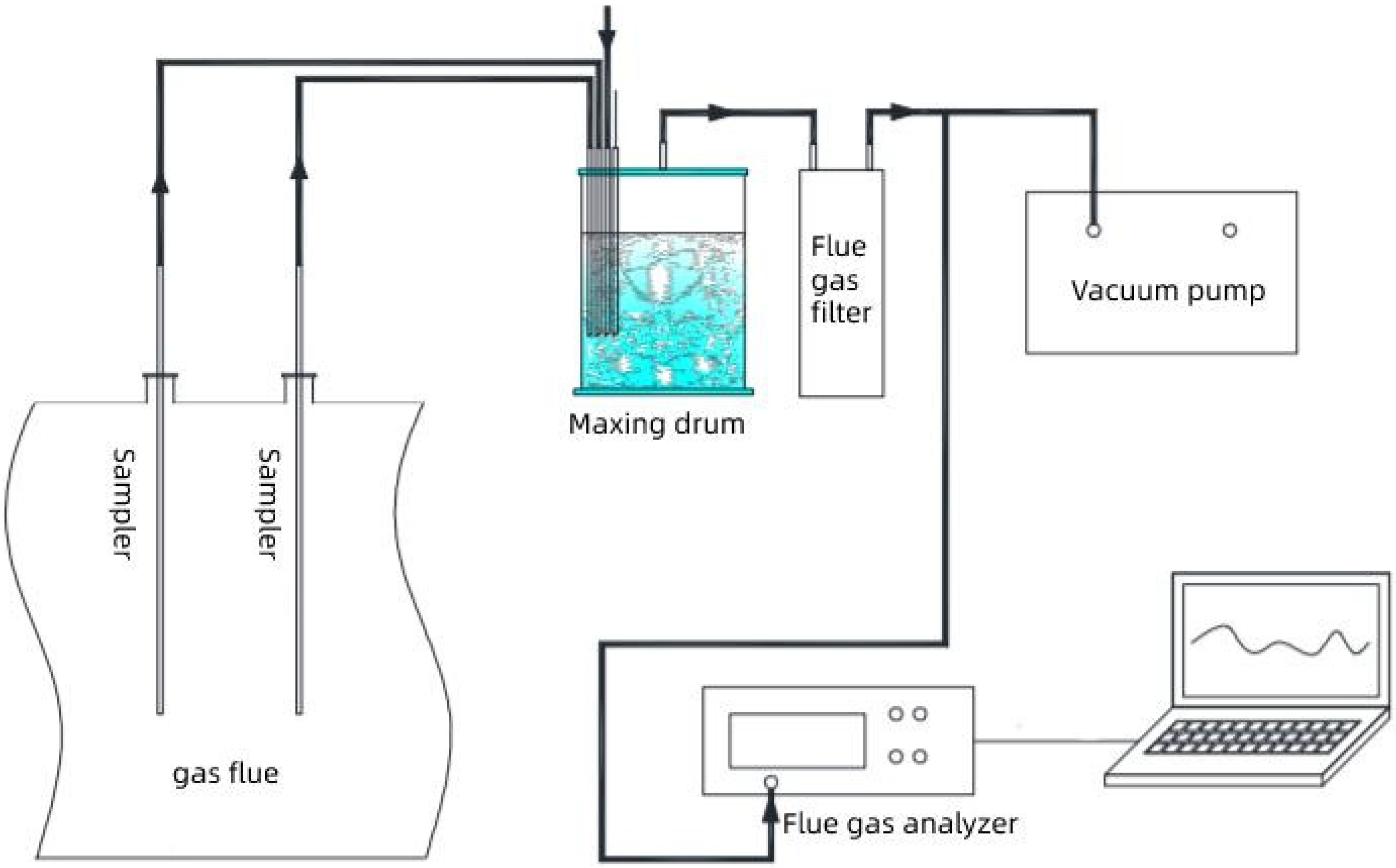
According to the grid method in GB/T10184-2015, 10 measuring points shall be arranged at the outlet of each APH and bypass mixed flue. The flue gas of each measuring point enters into the mixing drum through the sampler and rubber tube for mixing, and then it is introduced into the flue gas analyzer for detection after mixing. The data is collected and saved by the computer, with the collection interval of 10 s and the connection is shown in
Figure 5.
The flue gas temperature measurement and flue gas composition measurement are carried out simultaneously. The thermocouple and the samplers are integrated. The thermocouple is connected to the digital temperature inspection instrument through the compensation wire, and the data is collected and saved by the computer. The layout mode is shown in
Figure 6.
The outlet of the mixed flue gas duct of APH and bypass is the outlet boundary of boiler flue gas, and the inlet of induced draft fan is the inlet boundary of primary and secondary air boilers. The heat loss of the tail flue and the electric dust removal process after APH and introduction of external heat by the induced draft fan are ignored. According to the measured flue gas composition and temperature, the heat loss of flue gas is calculated, and the boiler efficiency is calculated by the reverse balance method in GB/t10184-2015.
Table 3 shows the comparison of the experiment and simulation of main parameters of boiler operation.
The results show that the measured efficiency of the boiler is 95.70% at 100% load, the corrected efficiency is 95.49%, the calculated efficiency is 94.84% in the simulation results, and the relative error is only 1%; at 75% load, the measured efficiency of the boiler is 95.89%, the corrected efficiency is 95.67%, the calculated efficiency is 94.54%, and the error is 1.1%. The error is within the allowable range, which shows that the model of the boiler system is accurate.
3. Theoretical Analysis Basis
In order to analyze the influence of various factors on the recycling rate, it is necessary to establish the steam temperature control equation and conduct the basic analysis of the intermediate point temperature. Since the change of intermediate point temperature will lead to new steam temperature characteristics during unit operation, the influence of intermediate point temperature on FGR should be analyzed first. Then, the influence of other factors on FGR is analyzed when the steam temperature characteristic is constant.
3.1. Intermediate Point Temperature
The intermediate point temperature of the supercritical boiler refers to the working medium temperature in the steam water separator at the outlet of the water wall. The change of the temperature at the middle point directly reflects the flow rate of the cold wall of the effluent and the position where the large specific heat capacity area of the working medium extends into the furnace under supercritical pressure. If the temperature of the middle point is too high, the flow of the water wall will be reduced and the cooling capacity will be poor; if the temperature of the middle point is too low, it will lead to the operation of the separator with water and the water inflow of the superheater, which will affect the safe operation of the superheater. In the actual operation, the position of the middle point temperature and keeping the micro-superheat state, i.e., 10–30 °C higher than the saturation temperature or quasi-critical temperature, are of great significance to the efficient and stable operation of the unit.
In supercritical units, the phase change point temperature under separator pressure is defined as quasi-critical temperature, which can be calculated according to the following formula [
37]:
tnl is defined as the quasi-critical temperature at pressure p, °C; p is the separator pressure, Mpa.
3.2. Steam Control Equation
The steam control equation is the energy balance equation that reflects the change of heat transfer ratio of each component when the boiler operation condition variations. In the actual operation of the boiler, it is very simple and convenient to use the steam control equation to qualitatively analyze and quantitatively estimate the influence of the operation condition on the steam temperature without all the coal quality data. For simple calculation, the reheater parameters in the following formula are applicable to primary reheat steam and secondary reheat steam temperature.
For reheaters, the energy balance is:
For the water wall (including economizer), the energy balance is:
Define heat of vaporization
r1:
r is the FGR rate; Bj is the calculation of coal consumption, kg/s; Qzr and Qs are respectively defined as the heat transferred from the flue gas produced by 1 kg coal to the reheater and the water wall (including the economizer), kj/kg; Dzr is the mass flow rate of reheat steam, G is the mass flow rate flow of water wall, kg/s; qzr is the amount of heat absorbed by 1 kg of reheated steam, kj/kg; r1 is the enthalpy rise at the intermediate point; h1 is the specific enthalpy of the separator outlet; and hgs is the specific enthalpy of feed water, kj/kg.
In the reheater system, there is no desuperheating water to reduce reheat steam temperature,
where
hzr is the total enthalpy rise of reheater, kj/kg.
Define the desuperheating spray ratio
of each stage:
The relationship between superheated steam flow and water wall flow is obtained by mass balance:
where
Dgr is the flow of superheated steam.
Define reheater flow coefficient
d:
The following formula can be obtained by combining the above formulas:
The heat transfer in the boiler is a complex process. By changing the operation conditions, such as load, coal quality, excess air factor, and feed water temperature, the heat transfer in the boiler will be affected. The parameters in the equation are qualitatively analyzed through variable operating conditions and steam temperature control equation. Then, the inflection point of each parameter is quantitatively analyzed by simulation. Finally, the changing trend of FGR is summarized.
4. Simulation Results and Analysis
In this paper, the reheat steam temperature of the double reheat million kilowatt boiler is regulated at the flue gas side by means of FGR and flue gas damper. FGR is to extract a part of the flue gas with low temperature from the tail of the boiler and input it into the furnace of the boiler through the recirculation fan, so as to reduce the temperature of the furnace. In this way, the temperature of the reheated steam can be adjusted by changing the heat absorption ratio of the convection heating surface and the radiation heating surface to achieve the design amount. The FGR can reduce the furnace in the boiler, and the flue gas baffle is set in the tail flue of the boiler. The flue gas is divided into two parts. Through the opening and closing of the flue gas, the proportion of the flue gas in the two flue gas is changed, and the change of the flue gas quantity can change the heat absorption of the reheater, so as to achieve the purpose of regulating the reheat steam temperature.
Through the above system, the EBSILON model is built, and the FGR changes with different parameters under the design value of reheat steam temperature.
4.1. The Influence of the Intermediate Point Temperature on FGR
In the reference system, the change of FGR by changing the intermediate point temperature under different loads is discussed. Because we use the simulation software to simulate the system, the control of the intermediate point temperature is simpler than the actual operation, using the temperature components in the software to control it.
Table 4 is the design value of the intermediate point temperature under different loads of the reference system. The intermediate point temperature is determined by the saturation temperature plus the superheat of about 40~50 °C. The saturation temperature is the pseudo-critical point temperature, which is calculated from Equation (1). In order to ensure the safe operation of the unit, the design value of the reference system intermediate point temperature is taken as the maximum value, and the intermediate point temperature changes between the saturation temperature and the maximum temperature.
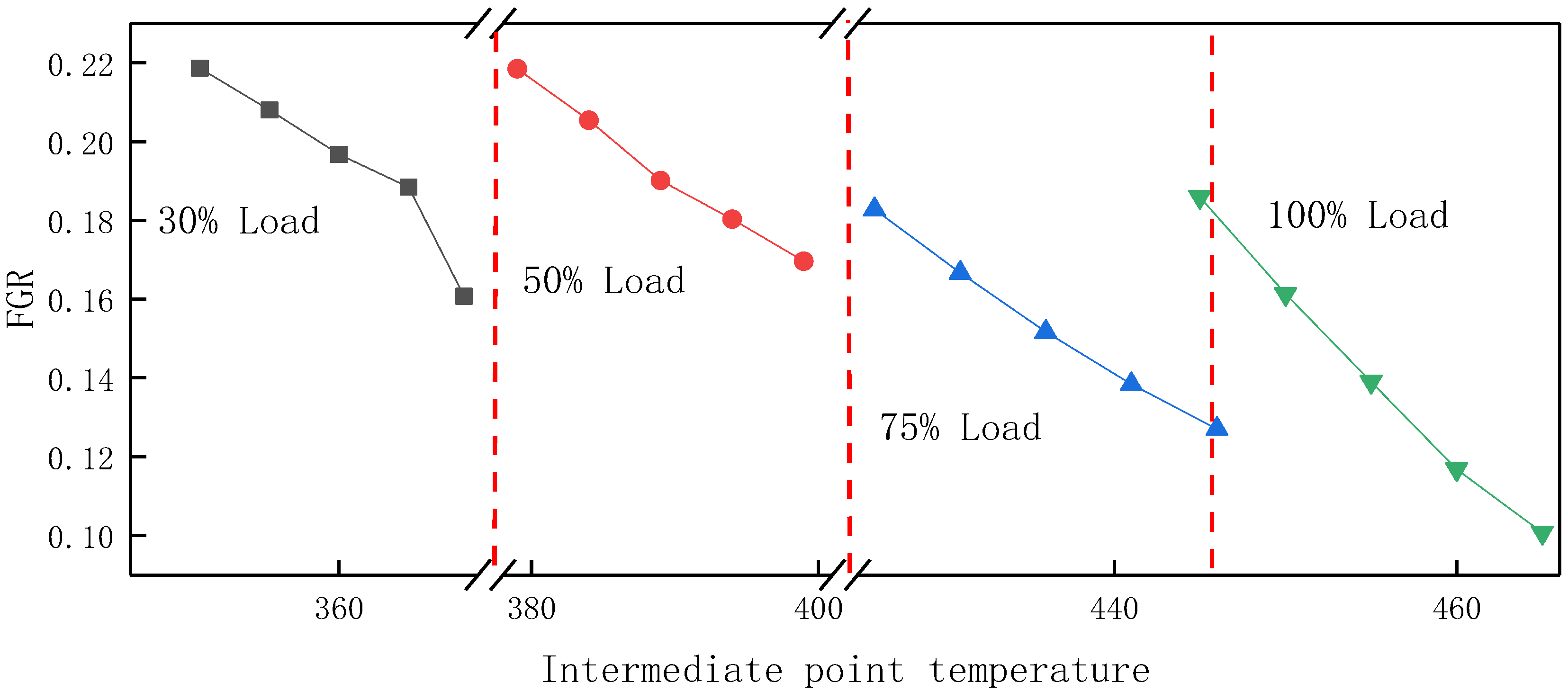
Figure 7 is a graph of FGR rate when the intermediate point temperature of the reference system is under four loads.
As shown in
Figure 7, under different loads, with the increase of the intermediate point temperature, the FGR rate decreases.
Table 5 is the parameter of the reference system under different loads; the coal consumption remains constant, the intermediate point temperature rises, the desuperheating water quantity of the superheater increases, the coal water ratio increases, and the flue gas temperature at the furnace outlet increases. In this process, coal consumption remains unchanged, and an increase in coal–water ratio means a decrease in water consumption. At the same time, the main steam temperature remains the same, and the heat from the coal to the water through the water wall will decrease, so the furnace outlet temperature will increase. The unit radiant heat in the furnace decreases and the total radiant heat also decreases, and the heat transfer of convection flue increases accordingly. The arrangement of the reheater is pure convection type, the heat absorption of the reheater is also increased, and the temperature of the reheater is increased—that is to say, with the increase of the intermediate point temperature and reheat temperature, when the temperature reaches 623 °C, there is no need for too much FGR, and the FGR rate decreases. Under the condition of 30% load, because the design value of the intermediate point temperature is too high, and the 30% load is abnormal, it is necessary to carry out fuel injection and combustion supporting processes to increase the intermediate point temperature, so as not to need too much FGR, so the inflection point appears.
Figure 8 shows the flowchart of the influence of intermediate point temperature on FGR. It can be seen from
Figure 8 that when the temperature change of the intermediate point is within the range of 20 °C, the change of flue gas recycling rate is the smallest at 50% load, reaching 4.88%, and the change is the largest at 100% load, and the change of flue gas recycling rate is 8.52%. The temperature change of the middle point has a great influence on the high load.
4.2. Influencing Factors of FGR Rate at Fixed the Intermediate Point Temperature
With the increase of the FGR, the heat absorption ratio of heating surface can be adjusted, so that the reheat steam temperature can be controlled within the safe operation range, the exhaust gas temperature can be reduced, the heat loss of exhaust gas can be reduced, and the emission concentration of nitrogen oxide can be reduced. However, the FGR is not the higher, the better. The change of the FGR is related to many factors. This section discusses the influence of load, excess air coefficient, coal quality, and feed water temperature on FGR rate under the condition of intermediate point temperature control.
In actual operation, it is necessary to control the temperature of the outlet of the water wall during the regulation process, so as to ensure this temperature is slightly superheated steam under any working condition, and the specific enthalpy at the outlet of the water wall can control the coal water ratio. If the intermediate point changes, the steam temperature will show new characteristics. The following studies are to study the change of reheat steam temperature and flue gas recirculation rate under the premise of the intermediate point temperature constant.
4.2.1. Load
The change of the FGR with the load is shown in
Figure 9. The overall trend of flue gas recycling is to reduce with the increase of load. When the load is higher than 75%, the change of steam temperature tends to be gentle, and the FGR rate is almost unchanged; when the load is lower than 75%, the FGR rate decreases with the increase of load.
When the load is lower than 75%, with the increase of fuel quantity, the load increases, the flue gas temperature at the furnace outlet increases, and the unit radiant heat
Qs in the furnace decreases. The reheaters are all pure convection heat exchangers, so the heat absorption of convection heating surface
Qzr increases. At the same time, with the increase of load, the enthalpy rise of the intermediate point
r1 decreases. Through the steam temperature control equation,
Qzr/
QS and
d/
r1 increase with the increase of load. From
Figure 9, the slope of the ratio of the former is always greater than that of the latter, so the enthalpy rise of reheat Δ
hzr increases with the increase of load. At low load, the rise of reheat enthalpy Δ
hzr is lower, and more FGR is needed to change the heat absorption ratio of heat exchanger in the boiler, so that the reheat steam temperature reaches 623°C. With the increase of the load, the reheat enthalpy rise Δ
hzr rises, and the FGR rate is reduced to keep the primary reheat steam temperature unchanged. At 50% load, the system gradually changes from low load to high load operation, the change trend of reheater heat absorption becomes slow, the change trend of
Qzr/
QS becomes slow, and the inflection point appears. In the same way, the trend of enthalpy rising at the intermediate point becomes slower, which leads to
d/
r1 becoming slower and to a turning point. From the steam temperature control equation, the above two ratio changes act on the reheat enthalpy rise, which makes the reheat enthalpy rise at 50% load tend to slow down, and there is a turning point.
When the system operates at a load higher than 75%, the enthalpy of the intermediate point decreases, which makes d/r1 increase. According to the steam control equation, the change of Δhzr tends to be gentle. In actual operation, the change trend of steam temperature in the boiler is stable from high load to full load, and the change of Δhzr is also slow, so the FGR is basically the same.
4.2.2. Coal Quality Change
In actual operation, the quality of coal put into the boiler is variable. Two kinds of coal different from the designed coal are put into the unit, and the components of the two kinds of coal are shown in
Table 1. Under each working condition, the premise of coal quality analysis is to ensure that the boiler evaporation does not change. The influence of two kinds of coal on FGR rate was studied by comparing the designed coal. The variation of the FGR under different loads of three kinds of coal is shown in
Figure 9. Under the same load, the FGR of coal 1 and coal 2 is lower than that of design coal, which indicates that the reheat temperature is higher than that of design coal, and the flue gas recirculation rate of coal 1 is the lowest.
The content of moisture, ash, and volatile matter in the three kinds of coal are quite different, but the difference of calorific value is relatively small.
Under the same load, only the coal quality is changed, the intermediate point temperature is unchanged, the reheat enthalpy rise
r1 at the intermediate point is almost constant, and the flow coefficient
d of the reheater remains fixed. It can also be seen from
Figure 9 that the ratio
d/
r1 of the two is unchanged. Among the three kinds of coal, the moisture content of coal 1 is the largest. When the moisture content of coal 1 is high, the theoretical combustion temperature decreases, the unit radiant heat
Qs decreases, the flue gas quantity increases, the flue gas temperature at the furnace outlet increases, and the heat transfer of convection reheater
Qzr increases. From the steam control equation, it can be concluded that the reheat enthalpy rise Δ
hzr of coal 1 is the largest, resulting in the lowest FGR of coal 1. Compared with the designed coal, coal 2 is low volatile and high ash coal. Because of this characteristic, it is difficult to ignite; the highest temperature area in the furnace will move upward, resulting in the increase of flue gas temperature at the furnace outlet; the unit radiant heat
Qs is smaller; and the convective heat transfer is relatively larger. From the steam control equation, it can be concluded that the temperature and enthalpy of reheated gas increase a little more, so the FGR of coal 2 is lower than that of the designed coal. Compared with coal 2, coal 1 is a kind of coal with high volatility and low ash. However, from
Figure 9, it can be seen that the unit radiant heat of flue gas of coal 2 is between design coal and coal 1, as is the rise of reheat enthalpy Δ
hzr. However, the rise of reheat enthalpy Δ
hzr of coal 1 is the largest, and the recycling rate of flue gas is the smallest. It can be concluded that under the same load, the influence of moisture content of different coal on flue gas recycling is the largest.
4.2.3. Excess Air Factor
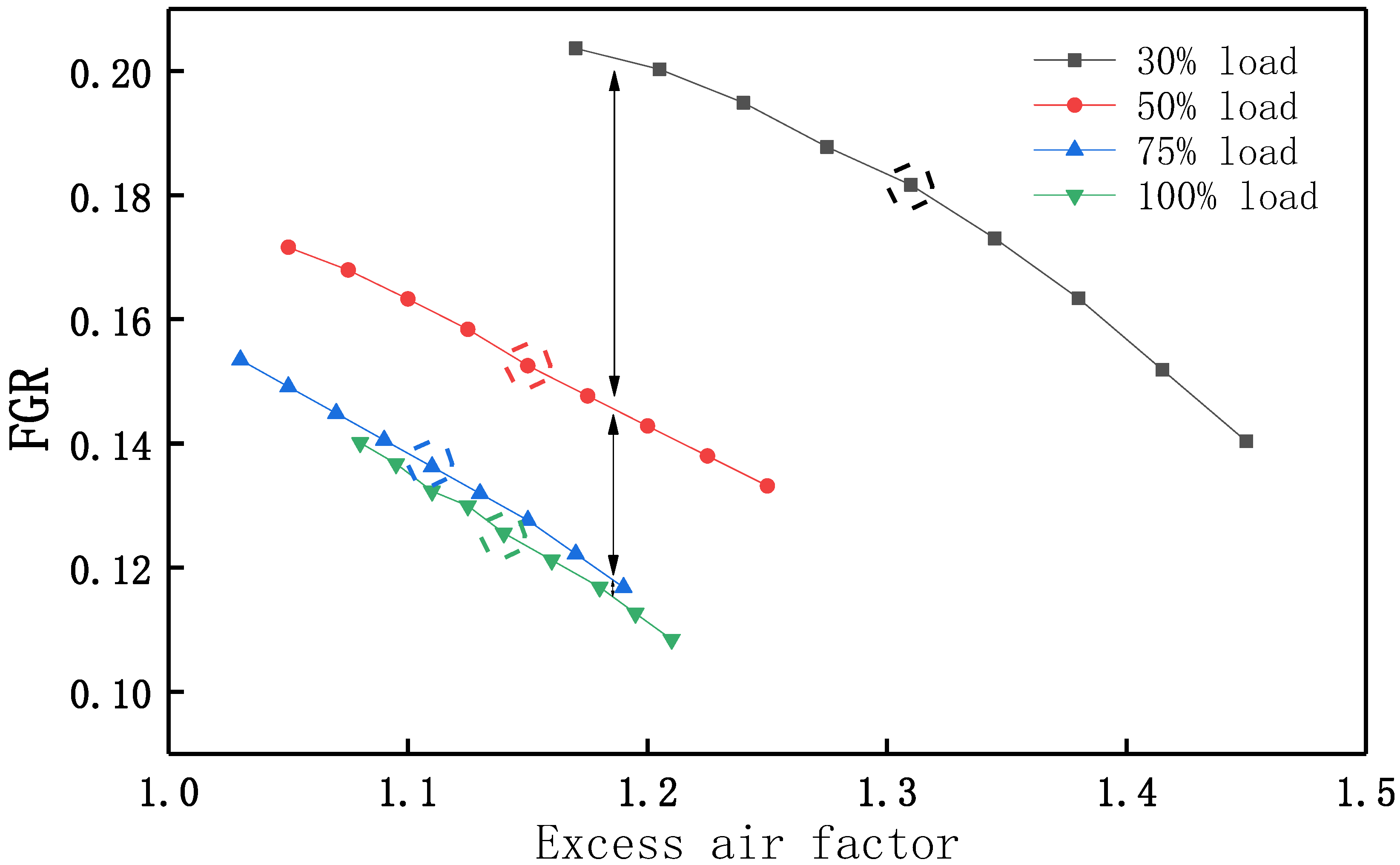
The influence of excess air factor on FGR rate is studied under the premise of given coal quantity and PA flow. By changing the SA flow, the excess air factor is calculated by the burner. In order to keep the reheated steam temperature unchanged, the controller adjusts the reheated steam temperature by regulating the amount of recycled flue gas and obtains the influence on the change of the FGR. The influence of excess air factor on FGR rate is shown in
Figure 10, and the design values of both under four working conditions are given. Under any load, the FGR rate decreases with the increase of excess air factor. It can be seen from the above that as the load increases, the system tends to be stable gradually, and the flue gas recycling rate tends to be constant from high load to full load, so in
Figure 7, the distance of the four curves becomes smaller gradually under four different working conditions.
Under any load, because the intermediate point temperature is unchanged, the enthalpy rise
r1 of the intermediate point remains unchanged, so the ratio
d/
r1 is a constant. As shown in
Figure 11,when the excess air factor increases, the flue gas temperature at the outlet of the furnace basically remains the same, the theoretical combustion temperature decreases, and the radiation in the furnace weakens, so the radiation quantity
QS of the water wall decreases; at the same time, the flue gas quantity increases with the increase of the excess air coefficient, the flue gas temperature at the outlet of each convection heating surface increases, the specific heat capacity and heat transfer coefficient of the flue gas increase, and the heat absorption quantity
Qzr of the convection heat exchange surface also increases. Therefore, the ratio of
Qzr/
Qs was positively correlated with the excess air factor. Through the steam control equation, it is easy to determine that the reheat enthalpy rise Δ
hzr also increases with the increase of excess air coefficient, and the FGR is the opposite.
4.2.4. Feed Water Temperature
After the high-pressure heater is cut off, when the feed water temperature is reduced and the load is constant, the boiler feed water needs more heat when it is heated to the same evaporation capacity. Considering the change of feed water temperature, the coal consumption increased slightly.
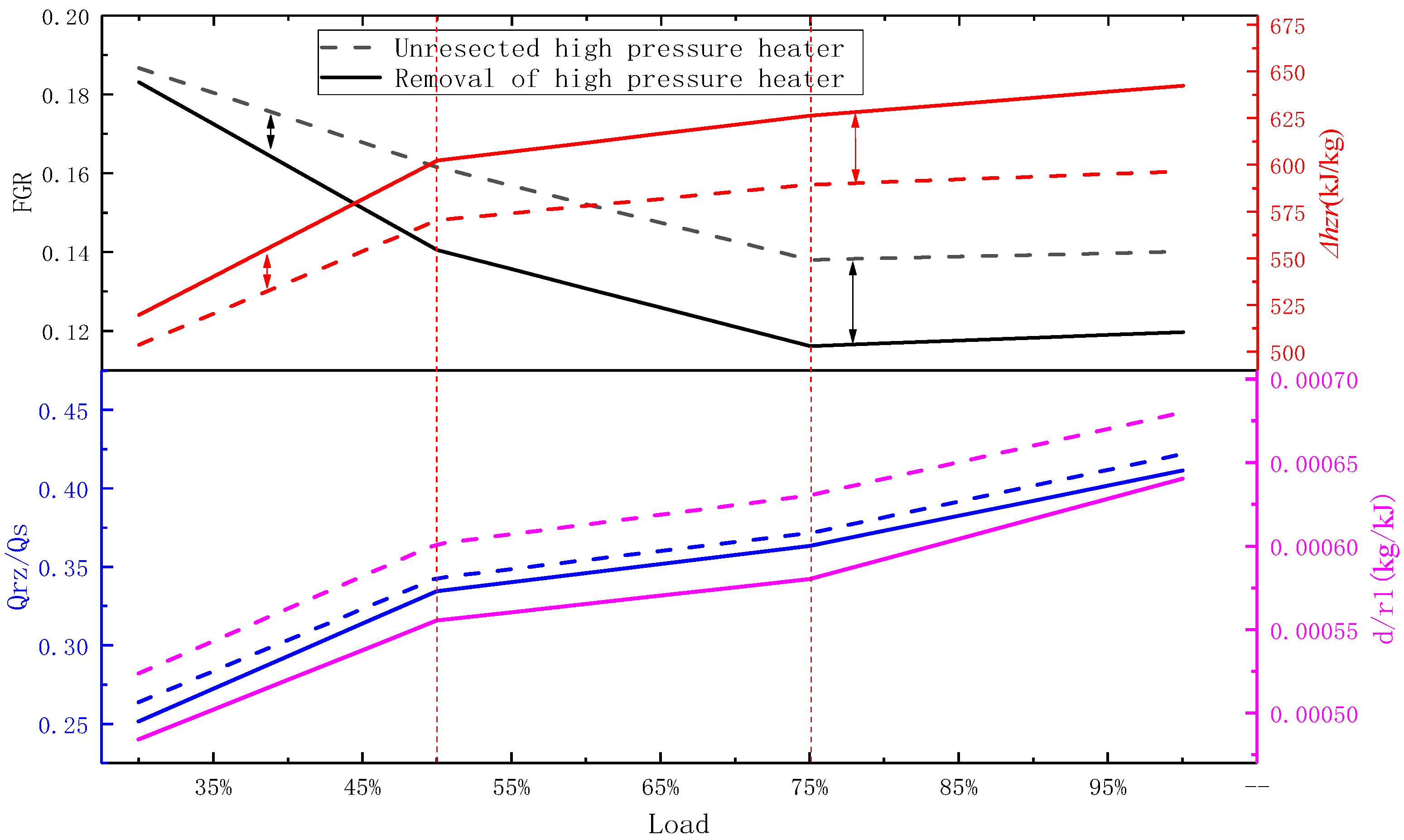
Figure 12 shows the influence trend of feed water temperature on the FGR under various loads.
It can be seen from
Figure 12 that under the same load, the feed water temperature decreases and the FGR decreases. After the high-pressure heater is cut off, the feed water temperature decreases, and the variation trend of each coefficient and the FGR in the steam control equation with the load is similar to the working condition of the high-pressure heater that is not cut off as a whole, the working condition of turning point is similar, and the reason is similar to that of the previous chapter, which will not be discussed here. This section mainly discusses the parameter change caused by the change of feed water temperature under the same load.
Under any load, the feed water temperature decreases after the high-pressure heater is cut off, and the enthalpy rise r1 of the intermediate point increases. At the same time, the working fluid entering the reheater increases due to the extrusion, which leads to the increase of the flow coefficient d of the reheater, but the increase is not large enough to offset the increase in r1. Therefore, with the increase of the feed water temperature d/r1 decreased.
After the removal of the high-pressure heater, the system load remains constant, the steam quantity reduces, and the unit steam work will increase inevitably. Then, the enthalpy value of reheat steam inlet will be reduced and the heat Qzr transferred from unit coal flue gas to the primary reheater is increased. However, the increase of Qs per unit radiant heat of water wall is larger than that of Qzr, so the ratio of Qzr/Qs decreases.
For the reheater, the steam pressure is low and the specific heat capacity is small. The sensitivity of the medium temperature rise of reheater to the change of the flue gas side is much greater than superheater, so the reheat enthalpy rise Δ
hzr increases after the removal of high-pressure heater. Through the steam control equation, under the same load, it is easy to get from
Figure 12 that the change of
Qzr/
QS before and after high cut is less than
d/
r1, so the reheat enthalpy rise Δ
hzr after high cut increases, and the amount of FGR required decreases, which is consistent with the theoretical analysis results.
It can be also seen from
Figure 9 that the feed water temperature difference before and after the high-pressure heater is cut off increases with the increase of load, and the reheat enthalpy Δ
hzr increase after the high-pressure heater is cut off. In other words, no extra FGR is required to increase the reheat temperature. Thus, the difference of FGR before and after high-pressure heater removal is also increased. From high load operation to full load operation, the temperature in the furnace tends to be flat, and the difference between Δ
hzr and FGR remains approximately the same.
4.3. CBF System
The CBF system is based on the reference system and removes the BPF used for heating part of the condensate and water supply. By comparing the changes of flue gas recycling in the two systems under the same conditions, the causes of the phenomenon are analyzed, which provides the basis for the economic analysis of different systems with or without flue gas residual heat utilization.
In order to study the influence of waste heat utilization of flue gas on FGR, this section explores the change of FGR of CBF system under off-design condition is discussed according to the above research process. The results show that the change trend of the FGR of the reference system and the CBF system with the influence parameters is approximately the same. Therefore, the main purpose of this section is to explore the change of FGR in both systems under any same state.
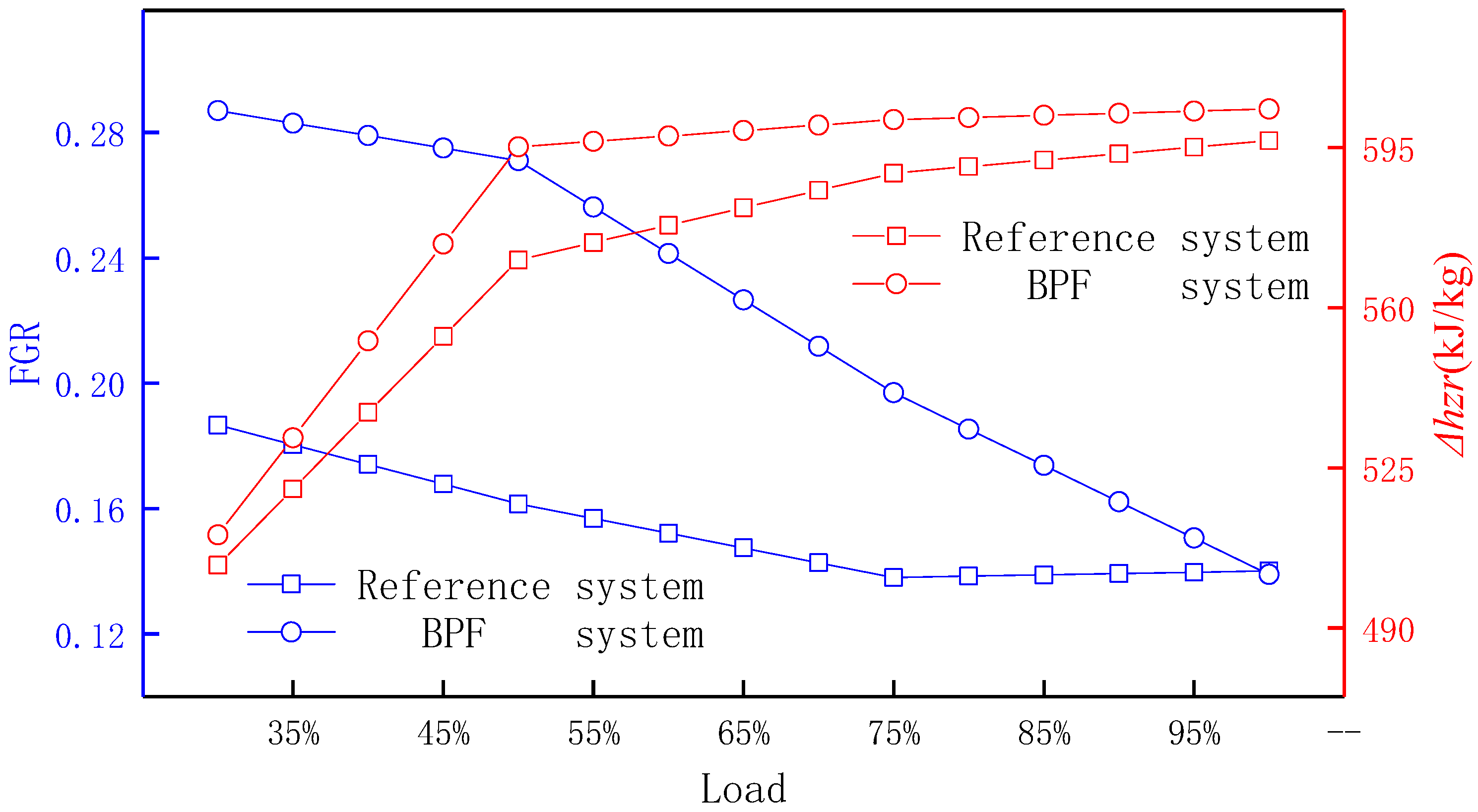
It can be seen from
Figure 13 that under the same load, the FGR rate and Δ
hzr of the CBF system are higher than the reference system. The reasons are as follows: compared with the CBF system, the benchmark system uses flue gas to heat part of the feed water, so the extraction steam will be squeezed out to increase the working medium entering the reheater, and the unit working medium work will be reduced, resulting in the increase of the enthalpy value at the reheater inlet. If the outlet state of reheater working medium remains unchanged, then the Δ
hzr will decrease, which is consistent with the simulation results. After removing the BPF, in order to keep the outlet temperature of reheater unchanged, it is necessary to increase the amount of FGR to ensure the efficient operation of the unit.


