Abstract
An advanced thermal conversion system involving high-temperature gasification of biomass and municipal waste into biofuel, syngas or hydrogen-rich gas is presented in this paper. The decomposition of solid biomass and wastes by gasification is carried out experimentally with a modern and innovative regenerator and updraft continuous gasifier, among others. A ceramic high-cycle regenerator provides extra energy for the thermal conversion of biomass or any other solids waste. Highly preheated air and steam gas (heated up to 1600 °C) was used as an oxidizing or gasification agent (feed gas). Preheated feed gas also enhances the thermal decomposition of the gasification solids for fuel gas. However, the main objective of this work is to promote new and advanced technology for the thermochemical conversion of biomass for alternative energy production. Selected results from experimental and numerical studies are also presented.
1. Introduction
The high-temperature air and air/steam (HiTAG/HiTSG) conversion process is an internationally recognized scientific area of new and advanced technology of thermochemical conversion of biomass and municipal waste into biofuels, syngas, hydrogen and electricity taking into consideration environmental impact and protection. The use of biomass and municipal waste for energy production in various forms is a subject of numerous ongoing research and development projects conducted by many scientific organizations [1,2,3]. Currently, four main methods of biomass and waste utilization methods are used: direct combustion, pyrolysis, biodegradation and gasification. The gasification is a process that converts, by partial oxidation, hydrocarbon materials into carbon monoxide and hydrogen. High-temperature conversion technology is capable of the highest overall degree of conversion and control for the broadest range of biomass and waste streams. Gasification could also convert various types of waste without any negative impact on the environment. Thermal conversion in a broad scope includes the application of four essential physio-chemical processes: drying, pyrolysis, gasification and combustion. Direct combustion of biomass and waste (for example on a grate) is not acceptable due to different pyrolysis and oxidative pyrolysis times for various materials present in the stream waste. Most biomass and municipal waste can be converted into fuel by gasification because the process is generally more efficient and cleaner than direct combustion. Furthermore, the research program on this issue was previously carried out by Royal Institute of Technology (KTH) Stockholm, Sweden and Gdansk University of Technology (GUT), Gdansk, Poland with the support of Tokyo Institute of Technology, Japan and University of Maryland (UM), USA [4,5,6,7,8,9,10,11,12,13,14,15,16].
Selected results of the present research were properly demonstrated and disseminated around the world and were acknowledged by the International Societies working with New Energy Conversion and Industrial Technology Development Organizations. It brings together some of the leading groups in Europe and, hopefully, will greatly enhance the European competitiveness with the USA and Japan in this critical area. Waste production, especially in Central Europe, is the ever-growing issue and its management requires efforts. Therefore, the development of a highly efficient and cost-effective concept will reduce the influence on environmental pollution and will even create additional workplaces for those involved in the conversion process of biomass and waste into gas fuel. The schematic layout of an advanced gasification system that utilizes the HiTAG/HiTSG process to convert biomass and municipal waste into biofuel (syngas) or hydrogen-rich gas is presented in Figure 1. The test facility presented in this figure consists of the following main components: slagging gasifier where feedstock is subjected to a high-temperature of the feed gas; ceramic regenerator where feed gas is heated to the required temperature; steam generator; H2 separating ceramic membranes; gas cleaning unit. A compact, high-temperature air regenerator (preheater) supplies high-temperature air or a mixture of air and steam for the conversion process. Figure 2 shows a conceptual diagram of a ceramic regenerator (preheater) developed by Nippon Furnace Kogyo Kaisha Ltd [5]. The regenerator allows preheating of air or a mixture of air and steam up to 1600 °C. Through HiTAG/HiTSG gasification it is possible to convert nearly any dry organic matter into clean-burning fuel. It can replace fossil fuel in the majority of applications and combat global warming. However, the main scope of this paper is to provide relatively new and advanced methods of high thermal conversion of biomass (through controlled blending and mixing, moisture control) and waste (wood pellets) to fuel gas in different conditions [17,18,19,20,21,22,23].
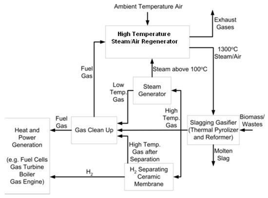
Figure 1.
Schematic layout of an advanced temperature air and air/steam (HiTAG/HiTSG) system in view of fuel gas or hydrogen-rich gas production.
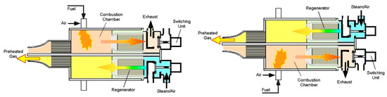
Figure 2.
Concept of a high-temperature air/steam ceramic regenerator with a high-frequency alternating flow (with about 10–30 s for each mode) developed by Mochida and Hasegawa [5].
2. Experimental Set-Up and Feedstock Characteristic
National and world gasification plants presented in this paper are in research and commercial stages, and unfortunately, they are often prone to failures due to the fact that the produced gas can have a high content of tar, ash or even dioxins and furans. Technology discussed in this paper can successfully mitigate this problem. As mentioned earlier, the biomass and municipal waste of different kinds have caused increased public awareness of the growing problem of threats to the natural environment. It seems that the best technology for processing wood and municipal waste is high-temperature gasification [1,2,3,4]. Fourteen types of materials used for the HiTA/HiTSG research study are shown in Figure 3. They include the most characteristic types of waste existing in various countries and regions around the world. They can be grouped in three main categories depending on their origin: agricultural waste (straw seeds, cashew nutshells, corn seeds, olive kernels, miscanthus pellets); industrial waste (plastic, electric cable shredder, tires, densified plastic waste, etc.); timber industry waste (charcoal, bark, wood chips, bamboo, salix). However, only the experimental results of wood pellet gasification are presented in this paper.
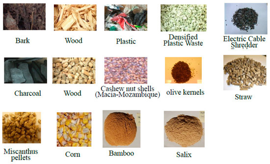
Figure 3.
Types of materials used for HiTAG/HiTSG conversions.
Due to chemical reaction in the bed and the feedstock failing speed (gravitation movement), gasification technology is divided into three basic types, i.e., gasification in a fixed-bed, continuous downdraft and updraft gasification. Of these three methods, fixed-bed gasification cannot be used in industrial systems since it is not designed to operate in continuous mode. In this method of gasification, a batch of feedstock (approx. 20 kg) is inserted into the gasifier and is subjected to high temperature. When the process ends, it is necessary to empty the gasifier and insert a new batch of feedstock. Because of that, this method is mainly used in laboratory conditions. Moreover, the gasification could be also divided into two processes according to the temperature of the feed gas: (a) low-temperature gasification—where cold or slightly preheated air is used as feed gas and (b) high-temperature gasification—where air or a mixture of air/steam is preheated to more than 1200 °C is used as a gasifying agent—feed gas (Figure 4).
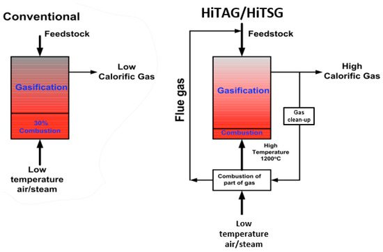
Figure 4.
Comparison between conventional and HiTAG/HiTSG gasification. In the conventional system, the process involves lower temperatures (approx. 600–700 °C) and produces a low-calorific gas polluted with tars, ash, or even dioxin and furans. On the other hand, in the HiTAG/HiTSG system, ceramic regenerator allows obtaining high temperatures of the feed gas (flue gas) which produces high calorific and cleaner gas.
Figure 5 shows a general schematic of HiTAG/HiTSG plant for fuel gas production from biomass and waste and then used for different purposes. The use of highly preheated air enriched with steam for gasification not only changes the energy balance but also the chemistry phenomena conversions process as well. Air enrichment by steam results in obtaining fuel gas with higher calorific value LHV than in case of gasification with air only. In the case of dry biomass, the obtained LHV values significantly exceed 8 MJ/Nm3 and they depend on gasification solid fuel (such as presented in Figure 3). An increase of feed gas temperature and stem reduce the production of tars, soot and char residue as well as increase the calorific value of syngas. The high lower heating value of fuel gas and high molar fraction of hydrogen and hydrocarbons produced by using HiTAG/HiTSG gasification technology could increase the technical possibilities of the application of fuel gas.
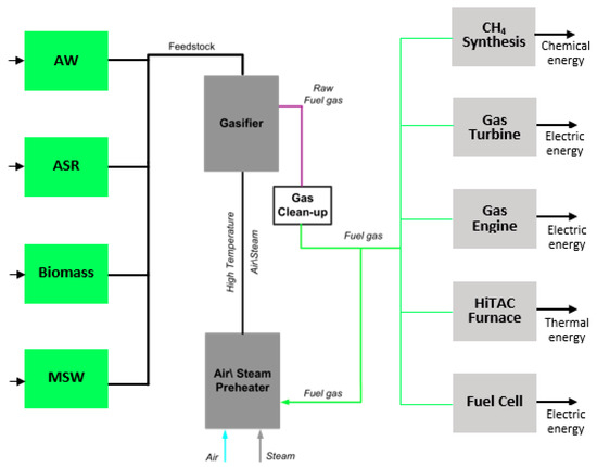
Figure 5.
General schematics of HiTAG/HiTSG plant for different utilization alternatives of the fuel gas obtained from biomass and waste (AW—Animal waste; ASR—Automotive shredder residues; MSW—Municipal solid waste). High calorific gas produced in the process can be used as fuel gas in energy generation based on turbine engines, furnaces, or fuel cells.
2.1. Batch Type Updraft Gasifier
Investigations on HiTAG/HiTSG in KTH/GUT were initially performed using batch type downdraft fixed-bed gasifier followed by a continuous downdraft. The downdraft gasifier was later transformed into an updraft-type one [6].
As shown in Figure 6, the gasification process was carried out in a reactor in the shape of a cylinder with a height of L = 0.9 and a diameter of D = 0.4 m. During the gasification process, the feedstock (c.a. 20 kg) is loaded batch-wise into a gasifier that is 0.35 m high and placed 5 cm above the ceramic grate-beads. The start-up of the gasification process includes all operations required until a steady state is stable. The shut-down procedure includes all the actions to seal the gasifier. After the reactor cooled down, the top section of the gasifier was opened to allow careful removal and monitoring of all the ash and/or slag. The following gas components of the fuel gas are measured: hydrogen (H2), carbon monoxide (CO), carbon dioxide (CO2), nitrogen (N2), oxygen (O2), methane (CH4) and higher hydrocarbons (CxHy). The composition of fuel gas was determined from gas samples taken at the gasifier outlet. All measurements (including temperatures, pressure along the air-lines and fuel gas composition) of distribution parameters were performed using a sampling frequency of one sample per 115 s.
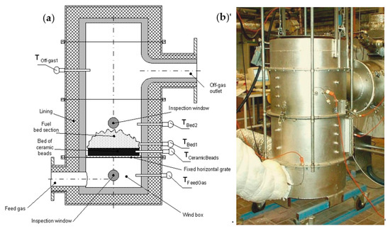
Figure 6.
Side view of an updraft gasifier (TFeed Gas—temperature of preheated feed gas, TBed1; TBed2—reacting fixed-bed, fuel gas TOff-gas1 and ceramic beads TCeramic Beads) (a), and batch type slag reactor HiTAG/HiTSG (b).
2.2. Continuous HTAG/HTSG Test Facility
The HiTAG/HiTSG test facility to be operated in continuous mode is presented in Figure 7 and Figure 8. The fuel was fed from the top of the reactor using a continuous feeding system where feed gas was conducted from the bottom. HiTAG/HiTSG experimental stand is equipped with the following main devices:
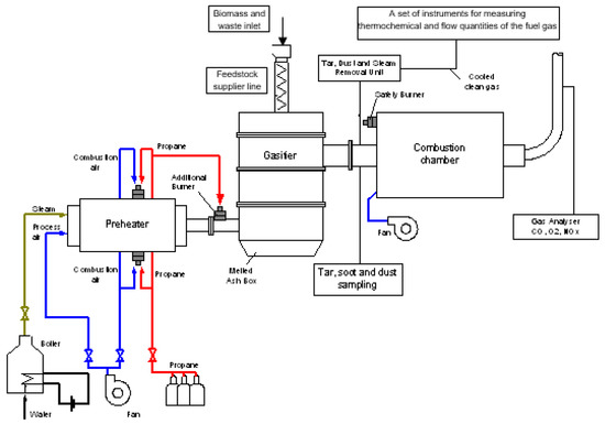
Figure 7.
HiTAG/HiTSG test facility with a continuous gasifier.
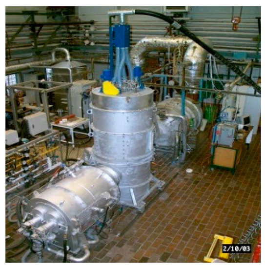
Figure 8.
Experimental stand for continuous downdraft gasification.
- Cylindrical-type reactor;
- Afterburning combustion chamber (shortly called afterburner) to burn fuel gas;
- Electrical heater to preheat feed gas in the lower range of temperatures (below 600 °C);
- Highly preheated air or air/stem regenerator;
- Feedstock supplier system;
- Electrical steam boiler;
- Air blower supplying air into heaters and next to the gasifier;
- Flue gas fan;
- Set of flow meters and pressure measurements devices;
- Gas Chromatograph (GC) and data acquisition system.
The gasification process takes place in the gasifier where the feedstock is loaded from the top, by means of the conveyor. The air and steam mixture are preheated in the regenerator heated initially with propane gas and later with part of the fuel gas produced in the gasifier. Since this is only an experimental stand, the rest of the gas is burned in the combustion chamber. In an operational plant, the rest of the gas is being used as fuel powering various devices such as energy generators, turbines, furnaces, etc.
3. Experimental Results
The following sections present some representative results for batch and continuous updraft tape gasification reactor.
3.1. Results of Fixed-Bed Gasifier Experiments
Typical results of gasification in the updraft fixed-bed gasifier with preheated feed gas as air are presented in Figure 9 and Figure 10. Figure 9 shows the gasification profiles obtained during the process involving wood pellets with preheating temperature of the feed gas equal to 350 °C, while Figure 10 shows the profiles obtained when the preheated gas temperature is 830 °C. In both figures two peaks of the formation of CO2 revealing the combustion process at the beginning and the end of the experiment. CO2 is consumed as the gasification progresses due to the Boudouard reaction (C + CO2 ↔ 2CO) favored by the high temperature of the gasifier bed reaching 1100 °C (Figure 9).
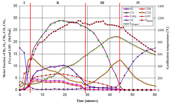
Figure 9.
Changes of the fuel gas composition (H2, CO, CO2, CH4, CxHy, O2), LHV, gasifier bed temperature (Tb1) and the exiting fuel gas temperature (Tog1), versus gasification process time. Feed gas conditions: 50 Nm3/h of air preheated up to 350 °C (gasification 20 kg of 12 mm wood pellets).
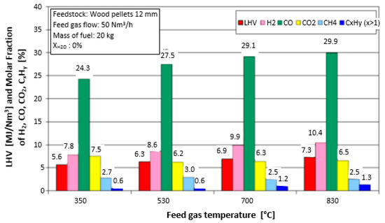
Figure 10.
Influence of the feed gas temperature on the average values of LHV and composition of dry fuel gas (gasification 20 kg of 12 mm wood pellets—computed results).
The average values presented in Figure 10 above were calculated from Phase II as a criterion for comparison of gasification experiments performed in the updraft fixed-bed gasifier operating in batch mode. Another criterion used in the calculations was to take the maximum lower heating value as a comparison criterion for different experiments. In the graph presented in Figure 10, the fuel gas quality is described by its lower heating value and the composition of species: hydrogen (H2), carbon monoxide (CO), carbon dioxide (CO2), methane (CH4), higher hydrocarbons (CxHy) and nitrogen (N2).
3.2. Results of HiTAG Experiments
As was mentioned earlier, during the thermochemical conversion of biomass and municipal waste (feedstock) an experimental program was carried out involving air as gasification media in the first stage and mixture of air and steam in the second one. During the air gasification, the conversion process was stable after about 130 min from its beginning. It is presented in Figure 11 and shows that the major combustible products are H2, CH4, CO, CO2 and CxHy.
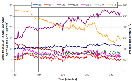
Figure 11.
Composition, lower heating value and temperature of produced fuel gas in the gasification period of experiments.
Figure 12 shows five basic gasification products as a function of the volumetric flow rate of the feed gas, temperatures and quantity of pellets. At the same volumetric flow rate of oxidizer (feed gas), input 103 Nm3/h, the molar fraction of carbon dioxide increases together with the feeding rate of pellets. The rest of the components stay even, with the exception of the decrease in methane content. The same trend can be observed for a lowered feed gas flow of 93 Nm3/h. The CO content is even higher than in the other case. This behavior can be easily explained if one takes into account the fact that such changes lead directly to an increase under stoichiometric conditions. However, for all presented cases, the lower heating value remains stable and high, namely slightly above 8 MJ/m3. At this point, it is worth mentioning that the temperature of the fuel gas changes to a high extent from case to case, varying from 415 °C to 810 °C. Such a phenomenon results from energy demand for carrying out an endothermic and exothermic chemical reaction. More precisely, these needs can be divided into three phases. The first phase is the process of pyrolysis. The second phase is an exothermic reaction in which part of carbon is oxidized to carbon dioxide. In the third phase, part of carbon dioxide, volatile compounds and steam are reduced to carbon monoxide, hydrogen and methane. Results obtained for 93 Nm3/h of oxidizer (Figure 12) can be directly compared with those presented in Figure 13 for similar conditions observed in batch type gasification, i.e., (80 Nm3/h of oxidizer at 840 °C). The comparison of the influence of physio-chemical, thermal and flow rate parameters reveals the advantages of a continuous process performed in higher temperatures, in the form of higher LHV values. The methane content in fuel gas is also higher while the molar fraction of other components is similar. In biomass gasification, the gas can contain significant amounts of tars which can be eliminated by thermal cracking or by the use of a catalyst (catalytic gasification). The increase of gasification temperature above 750 °C [20] causes an increase in the gaseous product field and a decrease in the tar yield. Due to technical applications, even small amounts of tare must be eliminated from fuel gas. These tars are mainly polyaromatic hydrocarbons (PAH) which are difficult to remove and their content increases with the gasification temperature.
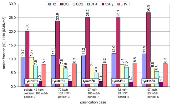
Figure 12.
Composition of fuel gas and its LHV for different conditions of continuous HiTAG and preheated air as the feed gas (experimental results).
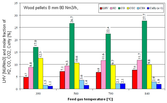
Figure 13.
Influence of temperature of the feed gas on the average values of LHV and composition of dry fuel gas. Average values are taken from Phase II for batch type gasification 20 kg of 8 mm wood pellets.
3.3. Results of HTAG/HTSG Investigations
The results of computed wood pellets gasification with HiTAG/HiTSG show that the highest concentration of desired gaseous products (hydrogen, carbon monoxide and methane) in produced syngas can be achieved only when steam is used as a gasifying agent (see Figure 14 and Figure 15) [9]. Steam controls the gasification temperature if the preheated air and steam mixture is used [6,8]. The gasification temperature response to the change of the feed gas composition and temperature is also arguable. The results showed that the use of steam in the feed gas sharply decreases the process temperature. An increase of the feed gas temperature reduces the production of tars, soot and char residue, as well as increases the heating value of the dry fuel gas produced. Results of mathematical modeling of gasification using high-temperature air, show that increase of the feed gas temperature results in a higher gasification rate, higher molar fractions of H2, CO and CxHy, hence higher LHV and a faster ignition rate [5].
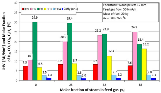
Figure 14.
Influence of molar fraction of steam on the average values of composition and lower heating value of the fuel gas—gasification of 20 kg of 12 mm wood pellets (computed results).
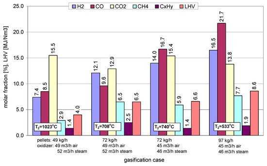
Figure 15.
Composition of fuel gas and its LHV for different conditions of continuous HTAG with a preheated mixture of air and steam as the feed gas (experimental results).
The high-temperature air/steam gasification technique has been tested for fuel in pellet form made from the waste material of wooden and plastic origin. The feedstock was gasified in an updraft fixed-bed reactor by mixtures of air and steam (4% to 82% steam) preheated to 1400 °C, a temperature well above the fluid temperature of the feedstock. HiTAG was reported as a good way of utilizing fuel containing plastic [10]. This technology was also used in experimental studies that were conducted using tropical coffee husks under high-temperature conditions [11]. A positive influence of high temperature on increasing the gasification process was found. Increased gasification temperature led to a linear increment of CO concentration in the syngas. Further investigation using two different types of gasifying agent: pure steam and 3% of oxygen at a temperature between 700 °C and 950 °C show that two undesirable phenomena occur: with increasing temperature of the process, the reaction rate decreases and there are no significant differences between steam and oxygen gasification rates. This indicates that increasing the temperature of the reaction is not always the best option to improve the gasification process and increase its rate, since this is not the only effect influencing the process performance [6].
4. Technoeconomic Study of HTAG/HTSG Energy Conversion
At the moment, it is very difficult to deliver reliable data on the technical and economic benefits of the new biomass and waste utilization system. However, one can make the following analysis: people are using natural resources every day, therefore more and more focus is put on efficient use or reuse of natural resources to avoid shortages in the future. Therefore, biomass and waste become more and more valuable sources of renewable energy. For comparison, short technical and economic studies of two processes, i.e., (a) direct combustion and (b) gasification of paper and wood conversion are presented below (Figure 16). Figure 17 shows an advanced gasification system utilizing high-temperature preheated air and steam to convert biomass and waste into synthetic fuel gas (syngas) and electricity that is currently being developed. Obviously, the most important part of the development is the slugging gasifier, FeG preheater, combustion chamber, drum dryer and electric generator. Taking into account the amounts of biomass and waste produced by society and industry, the energy benefits from the development of such technology are obvious. From an economic and technical point of view, apart from the obvious benefits for the protection of the environment, there are also considerable costs of such an investment. Below is an example of an estimation of gasification costs of 40 t/d of paper and about 10 t/d of sewage, commissioned by the pulp and paper industry, based on the research experience of the KTH Stockholm team, for a midsized municipality in Sweden. The estimation of costs of HTAG/HTSG conversion plant for the parameters listed below was commissioned to KTH by one of the Swedish municipalities:
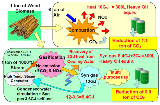
Figure 16.
Example of effective utilization of biomass energy (Combustion and Gasification). Comparison of two methods: direct combustion (top) and gasification (bottom) shows a significant reduction of harmful pollutants.
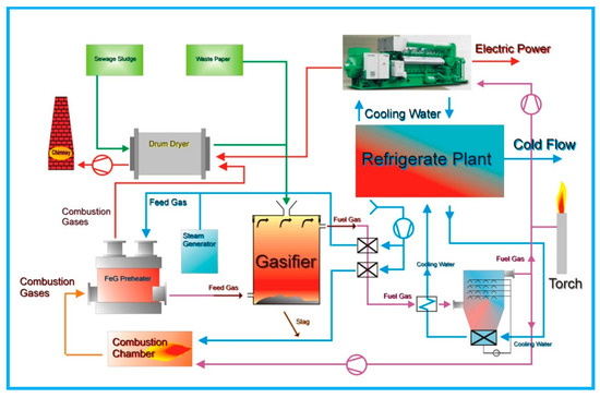
Figure 17.
A proposal of a semi-industrial high-temperature biomass gasification installation for power generation design by KTH/GUT research group. The key component of the system is the FeG Preheater which produces a high-temperature feed gas.
- Feedstocks: waste paper (40 t/d), sewage sludge (0–10 t/d);
- Prices: waste paper 10 Euro/t, sewage sludge −10 Euro/t;
- Electricity selling price: 0.1 Euro/kWh;
- Labor costs per 7.5 h shift: 40 Euro/worker, 50 Euro/engineer;
- Four engineers and four workers per day (1 shift on leave);
- Operating time: 200 days/y;
- LHV of waste paper (12–17 MJ/kg).
The above assumptions are illustrated in the Sankey diagram of energy flow (Figure 18) in relation to the Power Generation System shown in Figure 17.
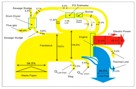
Figure 18.
Sankey Diagrams—HiTAG/HiTSG Power Generation System.
Table 1 presents the investment costs of the proposed installation for the high-temperature conversion of biomass and municipal waste into heat and electricity designed by the KTH/GUT research group.

Table 1.
Example of investment costs of the proposed semi-industrial power plant.
The cost of Euro 3,772,930 seems to be small due to large profits resulting from environmental protection and almost 0 emissions of harmful carbon, nitrogen and sulfur compounds (CO2, NOx and SOx) produced during classic methods of energy conversion and, especially, direct combustion of solid, liquid and gas fuels, biomass and municipal waste.
5. Examples of Typical Commercial Biomass Gasification Systems
As shown in Figure 19, the Weiss A/S power plant is a completely new “Tar-Free” two-stage gasification system with efficiency over 30%+ (normal plants only have 10–22%) [24]. Weiss is a green profile company, with long experience in environmental and efficiency-optimized combustion, for both industrial steam and district heating or even electrical power production.
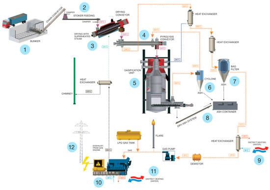
Figure 19.
Power Plant layout of the Weiss Tar-Free two-stage gasification system [24].
To sum up, the Weiss two-stage gasification systems for biomass is made in the three following sizes/types: 250 kWe,500 kWe and 1 MWe.
Nowadays, the developed Weiss two-stage gasification system is organized as follows:
- Woodchips are loaded in the bunker from trucks;
- Screw conveyors load the woodchips into the drying conveyor;
- Drying conveyor removes nearly all water out of the woodchips;
- Pyrolysis conveyor is dividing the woodchips in solids and gas;
- TAR is removed in the gasification unit;
- Larger parts are removed from gas in the cyclone;
- The remaining smaller parts are removed in the bag filter;
- Ash is continuously conveyed away from the gasification unit;
- Heat from heat-exchanger can be connected to the district heating grid;
- Purified gas is led into the gas-generator producing electric power;
- Heat-exchanger is connected to the gas-generator;
- The electric power is connected to the residential power grid.
Another well-selling wood gasification installation is the Wood-Spanner Re2 Gmbh system produced in Germany. The Wood-Spanner Re2 plant shown in Figure 20 consists of gasification and a CHP unit that generates electric and thermal power. The plant operates on a carbon-neutral basis that is used as fertilizer in Germany. Due to the modular design, a power range from 9 kWel to 3 MWel can be achieved by a biomass power plant.
Figure 20.
Electricity and heat from the Wood-Spanner Re2 Gmbh system [25].
6. Conclusions
The presented results concerning HiTAG/HiTSG technology proved to be very useful for gas fuel, hydrogen or syngas generation. The high temperature of the process generated in the preheater eliminates harmful substances such as tars, dioxins and furans which can be produced in low-temperature conversion processes. The fuel gas can be later used to produce heat and electricity, or even hydrogen by means of the separation process.
HiTAG/HiTSG systems can be introduced in industrial plants to deal with generated waste and also to provide energy that can be later used in the production/operation of the factory. Moreover, this technology can be useful in meeting the zero-emission goals.
Conducted experiments proved that the higher temperature of the gasification process yields cleaner gas of higher calorific value than in case of low-temperature processes, such as circulating, pebble bed or fluidized bed gasification.
This gas can then be freely used for different purposes, but the most profitable one seems to be small-scale electricity production using turbines, engines or fuel cells. In the energy sector, applications like boilers, chemical reactors, gasifiers are effective methods of substantial (conventional) fossil fuel consumption reduction and thus restricting the CO2, dioxin and furans emission.
Finally, this novel and unique technology (supported by many years of experimental research performed at GUT (Poland), KTH (Sweden) and UM (USA)) could ensure significant energy savings of more than 30%, downsizing of equipment, very low NOx emissions (around 50%) and harmful pollutants reduction (about 25%) [4,26,27,28,29]. This technology has tremendous potential for many applications, primarily energy-saving and fulfills all new regulations on waste incineration proposed by the European Commission.
In order to determine the influence of pressure on the gasification efficiency, further studies of the HiTAG/HiTSG process are planned in the future.
Author Contributions
Conceptualization, J.S.; formal analysis J.S. and M.S.; investigation, J.S.; resources, J.S.; data curation, J.S.; writing—original draft preparation, J.S. and M.S.; writing—review and editing, M.S.; visualization, M.S.; supervision, J.S. All authors have read and agreed to the published version of the manuscript.
Funding
This research received no external funding.
Acknowledgments
The work reported in this paper includes scientific cooperation between Gdańsk University of Technology, Gdańsk, Poland and Royal Institute of Technology (KTH), Stockholm, Sweden. The personal assistance of professor W. Blasiak and his help in experimental and numerical performance is kindly acknowledged.
Conflicts of Interest
The authors declare no conflict of interest.
References
- Li, S.; Zheng, H.; Zheng, Y.; Tian, J.; Jing, T.; Chang, J.-S.; Ho, S.-H. Recent advances in hydrogen production by thermo-catalytic conversion of biomass. Int. J. Hydrogen Energy 2019, 44, 14266–14278. [Google Scholar] [CrossRef]
- Oumer, A.N.; Hasan, M.M.; Baheta, A.T.; Mamat, R.; Abdullah, A.A. Bio-based liquid fuels as a source of renewable energy: A review. Renew. Sustain. Energy Rev. 2018, 88, 82–98. [Google Scholar] [CrossRef]
- Fasolini, A.; Cucciniello, R.; Paone, E.; Mauriello, F.; Tabanelli, T. A Short Overview on the Hydrogen Production Via Aqueous Phase Reforming (APR) of Cellulose, C6-C5 Sugars and Polyols. Catalysts 2019, 9, 917. [Google Scholar] [CrossRef]
- 2nd International Seminar on High Temperature Combustion in Industrial Furnaces; KTH: Stockholm, Sweden, 2000.
- Mochida, S.; Hasegawa, T. Development of highly preheated turbulent-jet generator. In Proceedings of the 3rd International Symposium on Advanced Energy Conversion System and Related Technologies, RAN2001, Nagoya, Japan, 15–17 December 2001. [Google Scholar]
- Donaj, P.; Blasiak, W.; Yang, W.; Forsgren, C. Conversion of microwave pyrolysed ASR’s char using high temperature agents. J. Hazard. Mater. 2011, 185, 472–481. [Google Scholar] [CrossRef] [PubMed]
- Zhou, C.; Stuermer, T.; Gunarathne, R.; Yang, W.; Blasiak, W. Effect of calcium oxide on high-temperature steam gasification of municipal solid waste. Fuel 2014, 122, 36–46. [Google Scholar] [CrossRef]
- Yang, W.; Ponzio, A.; Lucas, C.; Blasiak, W. Performance analysis of a fixed-bed biomass gasifier using high-temperature air. Fuel Process. Technol. 2006, 87, 235–245. [Google Scholar] [CrossRef]
- Blasiak, W.; Kalisz, S.; Szewczyk, D.; Lucas, C.; Abeyweera, R. High Temperature Air/Steam Gasification of Biomass and Wastes; Stage 2, Technical Report No.2, ISRN KTH/MSE–03/61-SE+ENERGY/TR; Publishing House of KTH University: Stockholm, Sweden, 2003. [Google Scholar]
- Ponzio, A.; Yang, W.; Blasiak, W.; Stasiek, J. Hydrogen generation from biomass using high temperature agent gasification from biomass using high temperature agent gasification. In Proceedings of the 16th European Biomass Conference and Exhibition, Feria Valencia, Valencia, Spain, 2–6 June 2008. [Google Scholar]
- Mikielewicz, D.; Stasiek, J.; Blasiak, W.; Ponzio, A.; Yang, W. Advanced Technology for Thermo-chemical Conversion of Biomass and Solid Municipal Wastes for Hydrogen-Rich Gas Production. In Proceedings of the 8th European Conference on Industrial Furnaces and Boilers, Vilamura, Portugal, 25–28 March 2008. [Google Scholar]
- Lucas, C.; Szewczyk, D.; Blasiak, W.; Mochida, S. High-temperature air and steam gasification of densified biofuels. Biomass Bioenergy 2004, 27, 563–575. [Google Scholar] [CrossRef]
- Ponzio, A.; Kalisz, S.; Blasiak, W. Effect of operating conditions on tar and gas composition in high temperature air/steam gasification (HTAG) of plastic containing waste. Fuel Process. Technol. 2006, 87, 223–233. [Google Scholar] [CrossRef]
- Wilson, L.; John, G.R.; Mhilu, C.F.; Yang, W.; Blasiak, W. Coffee husks gasification using high temperature air/steam agent. Fuel Process. Technol. 2010, 91, 1330–1337. [Google Scholar] [CrossRef]
- Donaj, P.; Yang, W.; Blasiak, W.; Forsgren, C. Recycling of automobile shredder residue with a microwave pyrolysis combined with high temperature steam gasification. J. Hazard. Mater. 2010, 182, 80–89. [Google Scholar] [CrossRef] [PubMed]
- Tsuji, H.; Gupta, G.K.; Hasegawa, T.; Katsuki, M.; Kishimoto, K.; Morita, M. High Temperature Air Combustion: From Energy Conservation to Pollution Reduction; CRC Press: Boca Raton, FL, USA, 2002. [Google Scholar]
- Lucas, C.; Szewczyk, D.; Blasiak, W. Fuel gas production from High Temperature Air and Steam gasification of biomass wastes. In Proceedings of the International Conference on Incineration and Thermal Treatment Technologies (IT3), Orlando, FL, USA, 12–16 May 2003. [Google Scholar]
- Blasiak, W.; Szewczyk, D.; Lucas, C.; Abeyweera, N.R.; Jansson, A.; Bjorkman, E. High Temperature Air/steam Gasification; STAGE 1 Technical Report Nr1. ISRN KTH/MSE–03/01 SE+ ENERGY/TR; Publishing House of KTH University: Stockholm, Sweden, 2003. [Google Scholar]
- Abeyweera, R. Energy Balance of the High Temperature Air/Steam Gasification of Biomass in Heat and Power Generation Process. Master’s Thesis, KTH, Stockholm, Sweden, 2003. [Google Scholar]
- Stasiek, J.; Jewartowski, M.; Yang, W. Small scale gasification of biomass and municipal wastes for heat and electricity production using HTAG technology. E3S Web Conf. 2017. [Google Scholar] [CrossRef]
- Stasiek, J.; Yang, W.; Yueshi, W. Modelling of biomass and municipal wastes conversion into heat, electricity and/or hydrogen using HTAG. In Proceedings of the 15th UK Heat Transfer Conference, Brunel University, London, UK, 4–5 September 2017. [Google Scholar]
- Stasiek, J.; Jewartowski, M. Conversion of biomass and municipal wastes into syngas and hydrogen using highly preheated agent (HTAG). In Proceedings of the 36th UIT Heat Transfer Conference, Sicily, Catania, Italy, 25–27 June 2018. [Google Scholar]
- Garcia, L.; Sjavador, M.; Araujo, J.; Bilbao, R. Catalytic Steam Gasification of Pine Sawdust. Effect of Catalyst Weight/Biomass Flow Rate and Steam/Biomass Ratios on Gas Production and Composition. Energy Fuels 1999, 13, 851–859. [Google Scholar] [CrossRef]
- Available online: http://www.gasifiers.bioenergylists.org/files/weiss_combined_heat_and_power.pdf (accessed on 1 April 2020).
- Available online: https://www.holz-kraft.com/en/products/biomass-chp.html (accessed on 1 May 2020).
- Wu, Y. Computational Fluid Dynamics Modelling of Biomass Gasification in Fixed-Bed Reactors Using Highly Preheated Agent. Ph.D. Thesis, KTH, Stockholm, Sweden, 2014. [Google Scholar]
- Zaini, I.N.; Yang, W.; Jonsson, P.G. Steam gasification of solid recovered fuel char derived from landfill waste: A kinetic study. Energy Procedia 2017, 142, 723–729. [Google Scholar] [CrossRef]
- Kabalina, N.; Costa, M.; Yang, W.; Martin, A. Energy and economic assessment of a polygeneration district heating and cooling system based on gasification of refuse derived fuels. Energy 2017, 137, 696–705. [Google Scholar] [CrossRef]
- Pan, Z.; Chan, W.P.; Veksha, A.; Giannis, A.; Dou, X.; Vang, H.; Lisak, G.; Lim, T.-T. Thermodynamic analyses of synthetic natural gas production via municipal solid waste gasification, high-temperature water electrolysis and methanation. Energy Convers. Manag. 2019, 202, 112160. [Google Scholar] [CrossRef]
© 2020 by the authors. Licensee MDPI, Basel, Switzerland. This article is an open access article distributed under the terms and conditions of the Creative Commons Attribution (CC BY) license (http://creativecommons.org/licenses/by/4.0/).