Article

Optimal Design of Combined Two-Tank Latent and Metal Hydrides-Based Thermochemical Heat Storage Systems for High-Temperature Waste Heat Recovery

by
Serge Nyallang Nyamsi
1,
Mykhaylo Lototskyy
1 and
Ivan Tolj
2,*
1
South African Institute for Advanced Materials Chemistry, University of the Western Cape, Private Bag X17, Bellville 7535, South Africa
2
Faculty of Electrical Engineering, Mechanical Engineering and Naval Architecture, University of Split, Rudjera Boskovica 32, 21000 Split, Croatia
*
Author to whom correspondence should be addressed.
Energies 2020, 13(16), 4216; https://doi.org/10.3390/en13164216
Submission received: 14 July 2020 / Revised: 3 August 2020 / Accepted: 11 August 2020 / Published: 14 August 2020

Abstract

:
The integration of thermal energy storage systems (TES) in waste-heat recovery applications shows great potential for energy efficiency improvement. In this study, a 2D mathematical model is formulated to analyze the performance of a two-tank thermochemical heat storage system using metal hydrides pair (Mg2Ni/LaNi5), for high-temperature waste heat recovery. Moreover, the system integrates a phase change material (PCM) to store and restore the heat of reaction of LaNi5. The effects of key properties of the PCM on the dynamics of the heat storage system were analyzed. Then, the TES was optimized using a genetic algorithm-based multi-objective optimization tool (NSGA-II), to maximize the power density, the energy density and storage efficiency simultaneously. The results indicate that the melting point Tm and the effective thermal conductivity of the PCM greatly affect the energy storage density and power output. For the range of melting point Tm = 30–50 °C used in this study, it was shown that a PCM with Tm = 47–49 °C leads to a maximum heat storage performance. Indeed, at that melting point narrow range, the thermodynamic driving force of reaction between metal hydrides during the heat charging and discharging processes is almost equal. The increase in the effective thermal conductivity by the addition of graphite brings about a tradeoff between increasing power output and decreasing the energy storage density. Finally, the hysteresis behavior (the difference between the melting and freezing point) only negatively impacts energy storage and power density during the heat discharging process by up to 9%. This study paves the way for the selection of PCMs for such combined thermochemical-latent heat storage systems.

1. Introduction

Despite their environmental effect and depletion, fossil fuels are still the main energy source for many applications. In power plants and the transportation sector, only 20–30% of the chemical energy of fossil fuels is converted to electric power. The remaining (~60–70%) is wasted to the environment. Likewise, in industrial processes, part of the energy is wasted through flue gases or effluents [1,2]. Therefore, waste heat recovery methods allowing for energy efficiency improvement have gained prominence in recent years. These methods include organic Rankine cycle (ORC), thermoelectric generators, and thermal energy storage systems (TES). However, ORC and thermoelectric generators convert waste heat to electricity with very low energy efficiency in the range ca. 2–15% [3,4,5,6]. Besides, these methods need to be installed near the waste heat source, which can make the overall installation (e.g., heat source + heat recovery systems) very costly [1]. For this reason, TES have become more appealing since they allow for a synchronization of heat source and demand. Moreover, they can be installed close to the waste heat source (on-site) or be transported to the users far away from the source (off-site). TES can be divided into three types: sensible heat storage, latent heat storage, and thermochemical storage. The latter two types are the most utilized in waste heat recovery applications since they can store a large energy density. Yu et al. [7], Magro et al. [8] investigated the coupling of phase change materials (PCM) with ORC to smooth the power generation given the high heat source fluctuation. The results indicated that coupling the PCM with ORC increased the thermal efficiency from 15.5 to 16.4%, while the energy density dramatically increased from 32 to 52%. Gopal et al. [9] conducted the energy and exergy analyses of PCM-based TES coupled with a diesel engine. The results indicated a significant improvement in energy and exergy up to 34.14 and 27.4%, respectively, alongside more than 6.13% of fuel-saving. Dispatch-able or mobile TES have been proposed to circumvent the long distance between the heat source (industrial sites) and end-users (cities) [10]. These TES predominantly used PCMs to store waste heat. Moreover, a techno-economic analysis of dispatch-able TES showed that its overall cost depends mostly on the price of the PCM and the transportation distance from the waste heat source to the end-users [11]. However, due to its low maturity level, only a few studies have discussed the possibility of Mobile-TES using adsorption materials or thermochemical materials such as zeolite, salt hydrates, etc. [12]. Thermochemical heat storage systems have an energy density within 2–10 folds higher than that of latent heat storage, which makes them even more appealing for solar energy and waste heat recovery applications. Many reviews on the current state-of-the-art of these systems are reported [13,14,15]. Regardless of the intended application, one of the widely accepted TES configurations is the use of coupled beds of solid (sorbent)-gas (sorbate) reactions, where the sorbate is used as a working fluid among beds [14,16,17]. One bed is filled with a sorbent that works at high temperatures, which is used for heat storage. The other bed contains a sorbent that reacts with the sorbate and rejects heat at low temperatures. There are different classes of thermochemical (sorbents) materials that fit the scope. In the literature, a great number of these thermochemical materials deals with ammoniated [16,17,18,19,20], hydrated salts [21,22,23,24,25] and metal hydrides [26,27,28,29,30,31]. Furthermore, each type of material has its own advantages and shortcomings.
An earlier study [21] reported a comparison between salt ammoniates and hydrates for cooling and refrigeration applications. Due to the low equilibrium temperature of NH3 (−77.7 °C) at atmospheric pressure, ammoniated salts are utilized for freezing (refrigeration) applications, while salt hydrates are utilized for cooling and heating applications. Furthermore, salt ammoniates possess low energy storage densities ranging from 0.166 to 0.51 kWhth/kg and 144–304 kWhth/m3 [16,17,18,19] as compared to those of some promising salt hydrates such as SrBr2.H2O, with 0.65 kWhth/kg and 250 kWhth/m3 [23]. However, salt hydrates have practical low energy storage density and efficiency. This is due to their melting and particles agglomeration [25] during the heat charging/discharging, which limit water permeation thereby reducing their cycling stability. Another critical issue in the use of salt hydrates is their corrosiveness towards metallic containers. Fernandez et al. [26] tested the corrosiveness of two type of salt hydrates, namely MgSO4.6H2O and SrBr2.6H2O, on different containers made of carbon steel, aluminum, copper and stainless steel. The results showed that containers made of carbon steel corrode at a fast rate (0.038 mm/year) compared to that of (<0.008 mm/year) other kind of containers.
Interestingly, metal hydrides offer even higher energy density compared to other thermochemical materials on the same metal basis, e.g., Mg-based hydrides have energy density in the range 0.52–0.8 kWhth/kg and 305–877 kWhth/m3 [27,28,29]. As a result, there is a renewed interest in using Mg-based hydrides for high-temperature energy storage applications.
In the metal hydrides-based TES presented so far, the low-temperature metal hydrides (LTMH) are limited to two types: AB5 and AB2 hydrides, for which their heat of reaction is within the range 20–30 kJ/mol-H2. If used in two-tank TES with Mg-based hydride, they generate or need a tremendous amount of energy, say up to 40% of the heat stored in the HTMH (Mg: 75 kJ/mol-H2). Therefore, the need for efficient thermal management is crucial to make such systems viable. To evade this problem of heat management, two solutions were proposed. The first is to replace the LTMH bed with a compressed H2 bottle [30]. However, energy is required for compression which also adds to the energy efficiency of the system. The other solution is to use passive heat management based on PCM [31,32,33]. In this scenario, the PCM liquefies or solidifies during the heat charging and discharging process, respectively. PCMs have been proposed and successfully applied to the thermal management of single hydrogen storage tanks [32,33], and more recently to two-tank TES for waste heat recovery applications [31]. It was shown that the thermo-physical properties of PCMs play a pivotal role in the performance of such systems. Two properties have stood out as the most crucial: the melting point and the thermal conductivity. Several authors suggested that the melting point Tm should be located in the midpoint of H2 absorption/desorption operating temperatures of the LTMH [33]. On the other hand, PCMs have low thermal conductivities, e.g., 0.24 W/mK for organic-based PCM [34] which is nearly five times lower than that of metal hydrides (e.g., 1.32 W/mK for LaNi5). As a result, this low thermal conductivity drastically affects the heat transfer between the LTMH and the PCM jacket. To increase the effective thermal conductivity of PCM, two methods are popularly proposed: the addition of nano-particles of carbon-based materials, or the insertion of metal foams and fins. Several results showed that the insertion of expanded graphite by 2.8 to 11.4 vol.% can improve the thermal conductivity by 170–190% [35]. Even more interestingly, the addition of metallic foams drastically enhances the effective thermal conductivity of PCM by 393.4 up to 12,300% [36]. Overall, the addition of these inert materials (graphite and metal foams) not solely improves the thermal conductivity, but also decreases the energy storage performance. For example, Ling et al. [37] showed that adding 25 and 30 wt.% of graphite in a paraffin leads to a diminishing of its latent heat from 226 kJ/kg to 168.1 and 152.5 kJ/kg, respectively. Others issues deriving from the addition of graphite or metal foams may be the alteration of the melting point due to the increase in the heat capacity of the PCM [35].
The analysis of previous works indicated that some aspects have not been taken into consideration and need to be addressed. First, every PCM shows a hysteresis behavior, meaning the melting point is different from the solidification/freezing point by 1 to 5 °C; see, for example, Figure 1 in [38]. This difference in temperature might affect the performance of the TES and will be explored in this study. Second, to what extent the addition of metal foams or carbon-based materials balances the improvement of PCM thermal conductivity and the decrease in energy storage capacity. Third, according to some studies, the melting point should be at the mid-range of the absorption/desorption temperatures [32,33]; however, no studies have pinpointed the PCM melting point that could correspond to the optimal performance behavior of the heat storage systems. Therefore, the objective of this work is to address the three issues mentioned above. To accomplish this objective, a 2D mathematical model studying the heat and mass transfer of the thermochemical heat storage system is formulated and analyzed in detail. Furthermore, a multi-objective optimization is performed to find the thermo-physical properties and size of the PCM that maximize the performance indicators of two-bed thermochemical heat storage systems using a PCM system to recover low temperature heat.

2. Mathematical Model

In this study, the thermochemical energy storage is comprised of a HTMH (Mg2Ni)/LTMH (LaNi5) pair for which the computational domain is presented in Figure 1. To understand the working principles of this proposed heat storage system, the reader should refer to our previous work [31]. Each metal hydride bed has the same thickness of 15 mm and the same length of 500 mm, with stainless steel (SS316L) walls of 2 mm thickness.
Assuming a porosity of 0.5, the weight of HTMH filled in the reactor is 0.791 kg, whereas that of LTMH is 2.078 kg. As a result, a maximum of 28.5 g of hydrogen can be exchanged between the beds. To scale up the TES, similar subsystems can be assembled to reach a desired energy storage density. The LTMH bed is enveloped with a PCM jacket to store/restore its heat of reaction. Furthermore, the jacket is fully insulated to limit the heat loss from the outer wall. The commercial-grade paraffin-based PCM has been chosen since it has several interesting attributes, such as low melting point (near room temperature, suitable for this application), low volumetric/thermal expansion (less than 10%) [33], and high range of melting point with constant thermophysical properties, among others [34,35]. As paraffin-based PCMs possess low thermal conductivity (0.24 W/mK), in this study we use graphite powder in different proportions to augment its thermal conductivity. Details of the system design and material properties are listed in Table 1.

2.1. Governing Equations

The following simplifications are made for metal hydride reactors [28,29,31] and PCM:
  • The thermo-physical properties of hydride are independent of temperature and concentration.
  • The thermal equilibrium between the gas and solid is established.
  • The radiative heat transfer is neglected.
  • The hysteresis in the equilibrium pressure is negligible for any material under study.
  • The thermo-physical properties (density, solid–liquid specific heat, thermal conductivity.) of the phase change materials are assumed constant.
  • The latent heat of phase change is temperature-independent.
  • The natural convection is disregarded since the system is laid horizontally. Therefore, gravity effect on the PCM is neglected.
  • The PCMs experience negligible or small (<5%) volume expansion. As a result, the density of PCM is constant in liquid and solid phase [33].
  • Energy balance
The average temperature of the metal hydride bed is computed by as follows:
ρ C p e f f T t   +   · ρ g C p g V T = λ e f f 2 T   +   1 ε M g ρ M H w t d α d t H
where the effective heat capacity and the thermal conductivity are calculated by assuming the volumetric phase mixing rule:
ρ C p e f f = ε ρ g C p g   +   1 ε ρ M H C p M H
λ e f f = ε λ g   +   1 ε λ M H
The energy balance of the reactor wall is expressed as follows:
ρ C p w a l l T w a l l t = λ w a l l 2 T w a l l
The energy balance of the PCM reads:
ρ p c m C p , e f f T p c m T p c m t = λ p c m 2 T p c m
The apparent heat capacity of the mixture is a linear function of the melting fraction of the phase change material, defined as follows:
ρ p c m C p , e f f T = ρ p c m C p P C M   +   Δ H p c m d f T p c m d T p c m
To improve the thermal conductivity, PCMs are composited with inert materials such as fins, metal foams and graphite. In that case, the effective heat capacity and thermal conductivity of the composite read as follows:
ρ C p p c m , e f f = 1 φ E G ρ p c m C p , p c m   +   Δ H p c m d f d T   +   φ E G ρ C p E G
λ p c m , e f f = 1 φ E G λ p c m   +   φ E G λ E G
where φ E G is the volume fraction of expanded graphite/metal foam added to the pristine PCM.
Mass balance
ε ρ g t   +   · ρ g V g = 1 ε ρ M H w t d α d t
where the gas speed in the porous bed is described by Darcy’s law:
V g = K e f f μ g p
However, in the connecting pipe, the hydrogen speed is governed by the transient Navier–Stokes momentum equation as follows:
t · ρ g V g   +   · ρ g V g · V g = p   +   μ g 2 V g
The reaction kinetics of metal hydrides considered here, LTMH (LaNi5) and HTMH (Mg2Ni) adopt the first order kinetic model [29,39] as follows:
Absorption process
d α d t = k a e x p E a R T l n p p e q 1 α
Desorption process
d α d t = k d e x p E d R T p p e q p e q α
The equilibrium pressure is expressed as follows:
ln p e q p 0 = H R T S R
The liquid fraction of PCM can be modeled by a smoothed Heaviside function as [40,41]:
f = 0 T p c m < T o n 0.5 1   +   e r f 6 T p c m T m 2 Δ T t r T p c m > T o n
where Ton, ΔTtr, and Tm are the onset melting temperature (beginning of the mushy zone), the mushy zone interval and the melting temperature (which is the peak temperature of the melting profile of a PCM). The relation between these three parameters is as follows: Tm = Ton + ΔTtr/2 [40].
Initial and boundary conditions
At t = 0, T0 = 20 °C (293 K), P0 = 1.96 bar, αHTMH = 1, αLTMH = 0, f = 0.
Two types of heat transfer continuity are considered:
Conduction/conduction heat continuity between two domains 1 and 2
λ 1 T 1 λ 2 T 2 · n = 0
Conduction/convection heat continuity at the reactor wall
λ w a l l T w a l l · n = h o i l T o i l T w a l l · n
The hydrogen flow continuity across the interface MH/connecting pipe
n · p M H p C P = 0
The adiabatic (axis-symmetry) boundary conditions are:
T r r = 0 = 0 ,   p r r = 0 = 0 , p r r = r M H = 0

2.2. Performance Indexes of the Heat Storage System

In this study, we will be interested in heat recovery performance. To assess this, three performance indexes are formulated as follows [31]:
  • The volumetric energy storage density during the heat discharging:
    Q d = h 0 A M H 0 t d T f , i T M H d t V T
    With A M H = 2 π r M H   +   δ L M H , where VT is the total volume of the heat storage components accounting for the MH beds and the PCM jacket, td is the heat discharging time,
  • The specific power during the heat-discharging step:
    Q ˙ d = Q d m H T M H × t d
    where mHTMH is the weight of the high temperature metal hydride.
  • The energy storage efficiency, which is the ratio between the useful heat output to the heat input:
    η = Q d Q c

2.3. Optimization Procedure

From the parametric analysis [31], it was shown that all the thermo-physical properties of the PCM affect the performance of the TES system. Therefore, it is judicious to apply an optimization exercise to find the ideal PCM for this specific application that maximize the performance indexes, simultaneously. Since in this study we have defined three of these indexes, maximizing each of these, leads to a multi-objective optimization. Therefore the problem formulation is given as follows:
Maximize   (   Q d ,   Q ˙ d   and   η )
Here, the design parameters are the thermo-physical parameters of the PCM, the PCM jacket size, the amount of expanded graphite,   φ E G to increase the thermal conductivity and the duration of heat charging and discharging, tc/d. Because of the slow melting/freezing kinetics compared to that of LaNi5, tc/d has been included as optimization variable in order to improve the amount of H2 exchanged between beds, during the heat charging/discharging process. The range of some of these optimization variables are listed in Table 2 along with the main simulation parameters. In addition, the graphite volume fraction φ E G is limited to 30% due to its restricted effect on the power output beyond a certain value, as will be shown in the following. On the other hand, the heat charging discharging is allowed to vary in 2 to 6 h range.
There are two main methods for solving multi-objective optimization: the weighted sum which combines the multiple objectives in one single objective or the evolutionary algorithm-based multi-objective optimization. The latter is generally popular to generate a set of optimal solutions (Pareto front). The problem defined above is solved by an evolutionary-based multi-objective optimization NSGA-II (Non-dominated Sorting Genetic Algorithm) algorithm developed by Deb et al. [42] as implemented in MATLAB utilizing the optimization toolbox “gamultiobj”. Since the optimization tool receives entries from a finite element analysis software (COMSOL) by solving the governing equations, Equations (1)–(19), the population and generations sizes should be limited due to time constraints. In this study, the basic parameters for the optimization algorithm are as follows: a population size of 10 individuals and maximum generation size of 60 have be chosen; the crossover and mutation rates are 0.80 and 0.05, respectively. Finally, it was observed that the optimization exercise took about 189 h using on our work station: DELL XPS Intel i7–8700 hexacore (12 threads) CPU @3.20 GHz (University of the Western Cape, Cape Town, South Africa).

3. Results and Discussion

The model is solved using two main modules in COMSOL Multiphysics V3.5a. The “Chemical Engineering Module” was chosen to solve the mass transfer and momentum transport (porous media flow). The thermal model was solved by heat transfer by convection and conduction in porous media under “Earth Science Module”. To ensure convergence and accuracy of the results, we used the same settings of the simulation (solver, relative and absolute errors, mesh size) already given in our previous work [31]. The computational domain was discretized into 4857 triangular mesh elements which ensure a compromise between computation time and results accuracy within 1%. Table 2 presents the thermo-physical parameters of the phase change materials used in this work. The melting point and the freezing point (Hysteresis behavior) were allowed to vary in the range given in the table, while others parameters were kept constant to those of the baseline RT35.

3.1. Model Validation

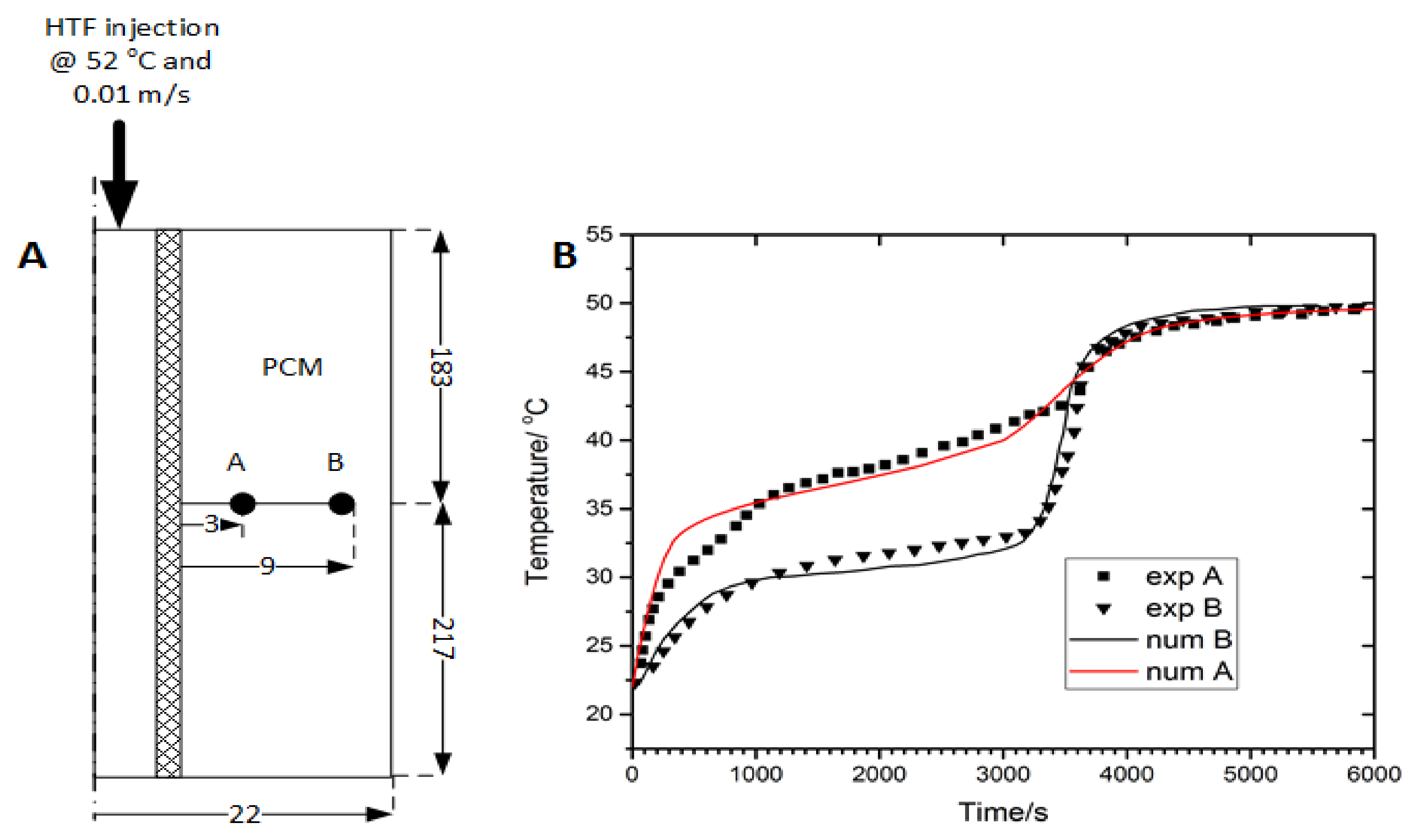
The mathematical model describing the metal hydride temporal behavior has been validated in our previous report [29,31] with experimental works presented in the literature. For the sake of conciseness, only the model describing the PCM will be further validated with available experimental work. To this end, we compared the model with experiments done by Longeon et al. [41]. The cross-section of the experimental reactor is depicted in Figure 2A. It consisted of two concentric cylinders, where a heat transfer fluid flows inside the inner cylinder and 400 g of PCM (RT35) was filled into the shell. The dimension of the experimental device is indicated in the figure. The shell had an OD of 44 mm and ID of 20 mm. the HTF tube had a dimeter of 15 mm, with a total length of 400 mm. For more details, please refer to the main article [41].
During the heat charging process, the HTF is injected from the top of the device at a constant temperature (52 °C) and velocity (0.01 m/s). The temperature distribution inside the PCM was monitored by 48 K-type thermocouples placed in different radial and angular positions. In this validation, only two points at a fixed radial position from the tube external wall, A (r = 3 mm) and B (r = 9 mm), have been considered. The heat transfer model considers the simultaneously solving of Equations (1), (4) and (5). Equation (1) is modified by removing the heat source and adjusting the thermophysical properties of hydrogen to the HTF (water). This corresponds to a heat transfer model with a laminar flow [41]. Figure 2B compares the temporal profile of the experimental data and the numerical ones. As can be seen, our PCM numerical model qualitatively captures the experimental temperature profile. However, it is also seen that at the initial stage, our model over-predicts the temperature by up to 3 °C, and then the errors start reducing in the phase transition and equilibrium stages (second and third segments of the temperature profile). Nevertheless, the overall relative error is within 5%. It must be noted, that the cumulative errors can be attributed to the uncertainty of the thermophysical properties of the PCM, the uncertainty of the heat transfer phenomena into the HTF tube and finally by the non-consideration of the natural convection from the outer wall of the experimental device, which has been proven to occur during the course of the experiments.

3.2. Effect of the PCM Melting Point on the Performance of the Storage System

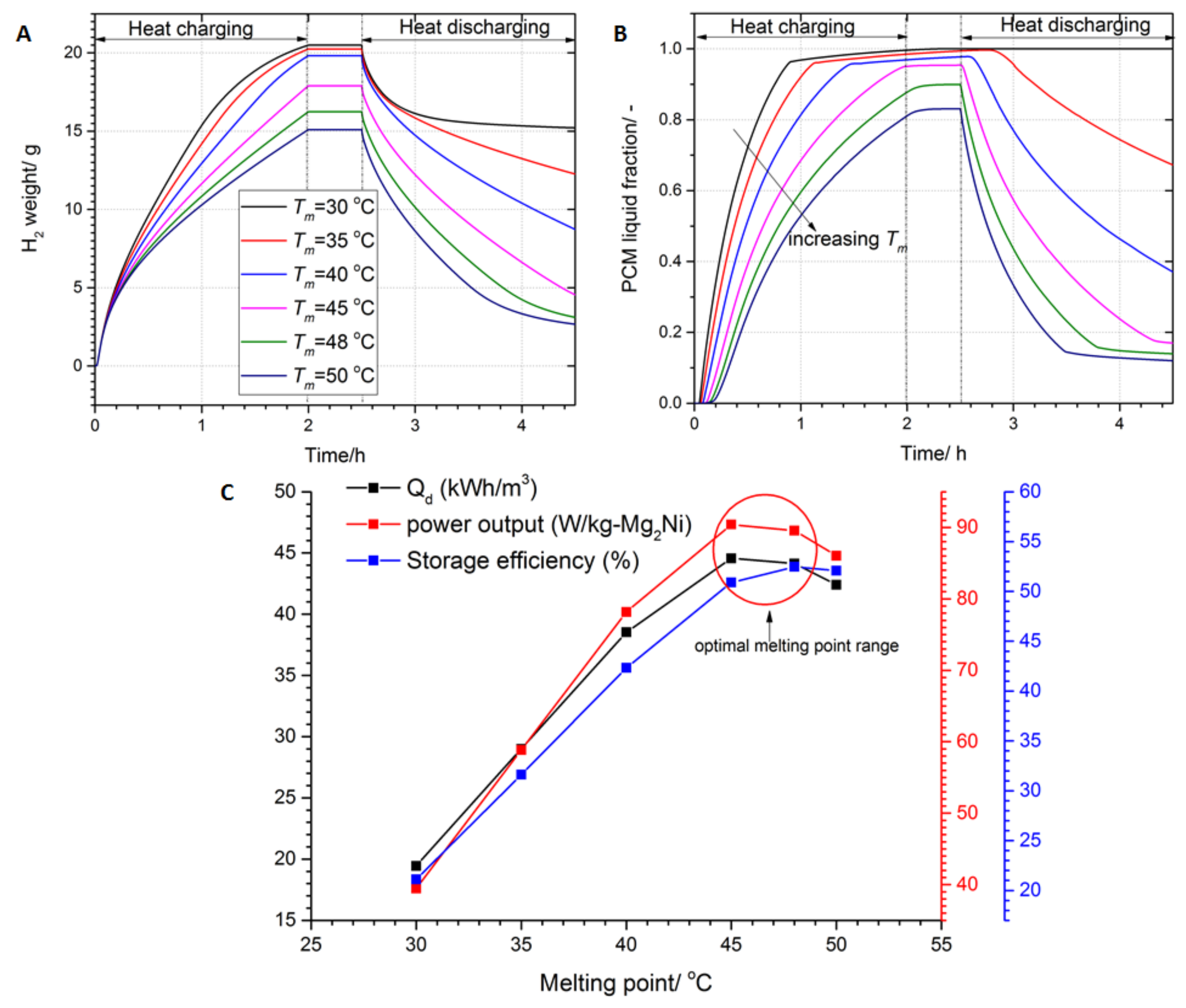
The performance of the system can be fully analyzed by investigating the melting behavior of PCM and the hydrogen transferred between the beds. Figure 3 shows the effect of the melting point on the H2 exchanged between bed, the melting fraction and temperature of PCM and the performance indexes. As can be seen from the figure, increasing the melting point promotes the heat discharging process while the heat charging process deteriorates.
This is because the driving force of the reaction (ratio of equilibrium pressure in HTMH to that of LTMH) declines as the melting point Tm increases (as can be seen from Table 3). As a result, using a PCM with Tm = 30 °C, the LTMH absorbs 20.49 g of hydrogen, which is 71.9% of its maximum capacity, during the charging process. In contrast, during the discharging process, only 5.27 g of H2 is desorbed from the LTMH bed. Furthermore, it is seen that the amount of transferred H2 is increased to a maximum of 13.35 g by using Tm = 45 °C. Figure 3C summarizes the effect of increasing the melting point of PCM on the performance of the storage system in terms of energy density, energy storage efficiency and specific power output. For instance, the energy storage density during the discharging is 19.44 kWhth/m3 for Tm = 30 °C and 29 kWhth/m3 for Tm = 35 °C, which is ca. 49.17% enhancement. Increasing further the melting point leads to the increase in any performance index to a maximum value then thereafter starts to decline. From the graph, it can be seen the melting point leading to maximum performance is located between Tm = 45–48 °C. Around this melting point, the thermodynamic driving force of the reaction is almost equal in the heat charging and discharging process (1.64–1.8), as can be confirmed in Table 3.

3.3. Effect of the PCM Hysteresis on the Performance Indexes

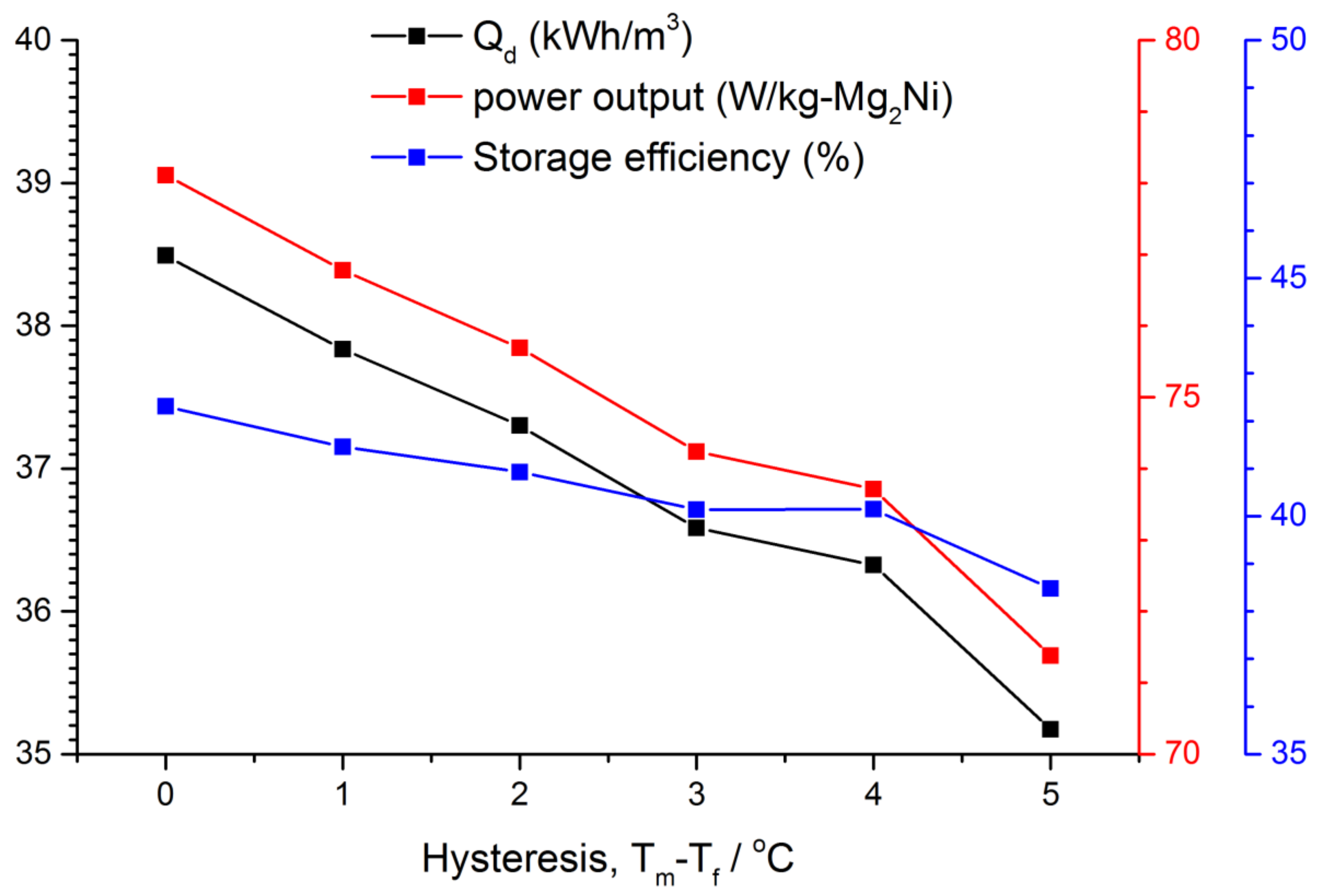
As mentioned in the introduction, any PCM displays a hysteresis behavior, where the melting point could be higher than the freezing point by 1–5 °C. For the simulation, the melting point is kept to Tm = 40 °C, while the freezing point changes from Tf = 35 to 39 °C. As can be expected, the diminishing of the freezing point affects the heat discharging process, as the H2 equilibrium pressure inside the LTMH bed decreases. Figure 4 displays the performance indexes of the TES as a function of hysteresis. It can be seen that all the indexes decrease as the hysteresis temperature raises from 1–5 °C. The energy density, the specific power output, and the energy storage efficiency tumble from the case without hysteresis (Tm = Tf) by a maximum of 8.6, 8.61 and 9%, respectively.

3.4. Effect of Thermal Conductivity Enhancement on the System Performance

Adding even a small volume/mass fraction metal foams/carbon-based materials has been shown to significantly improve the thermal conductivity of PCMs. However, this process not only increases the thermal conductivity but also changes the thermo-physical properties of PCMs, especially the thermal inertia. Sari and Karaipekli [43] claimed that the addition of up to 10 wt.% of expanded graphite has not altered the melting temperature. In another study, Ji et al. [44] indicated that the addition of ultrathin-graphite foams up to 1.2 vol.% enhanced the thermal conductivity by 18 times with no changes in the melting temperature and specific latent heat. Given these observations, the addition of graphite in PCMs brings about a change in effective thermal capacity and thermal conductivity as follows:
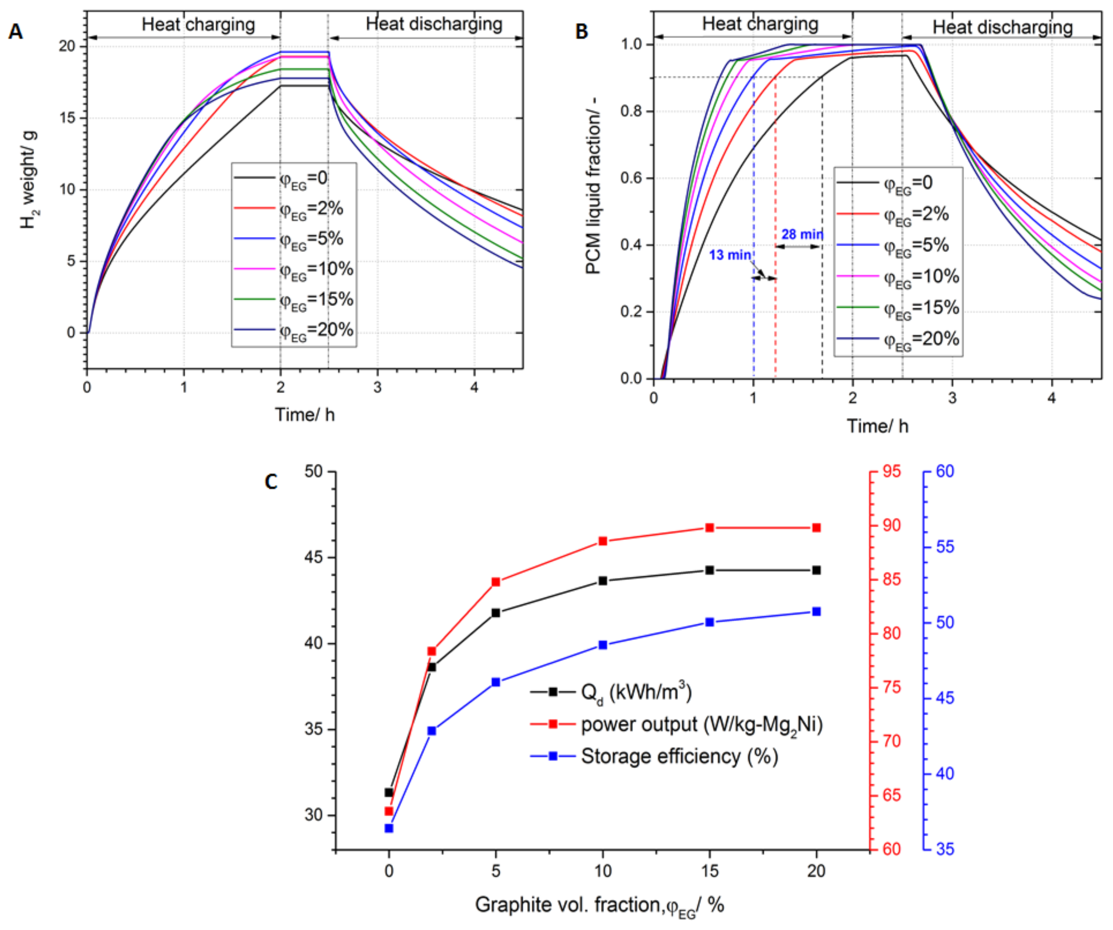
Using the above formula Equation (8), the effective thermal conductivity of PCM is found to be 0.5, 0.99, 1.75, 2.95, 4.175 and 5.4 W/mK for φEG = 0, 2, 5, 10, 15 and 20%, respectively. Figure 5 depicts the effect of graphite volume fraction on the system performance in terms of H2 mass absorbed/desorbed in LTMH, the melting fraction and energy, and power densities. It is seen that the addition of graphite quickens the melting process (Figure 5B), e.g., the addition of 2% of graphite reduces the PCM melting (90% melting fraction) time by 28 min compared to that with no graphite addition.
A further increase in graphite to 5% declines the melting time by 13.2 min. Although the same trend can be observed on the H2 absorption process into the LTMH bed (Figure 5A), it is noticed that the maximum H2 mass at the end of the heat charging process varies with the graphite volume fraction. In effect, at the end of the heat charging process, the H2 weights absorbed in LTMH are 17.29, 19.33 and 19.57 g for the volume fraction of 0, 2 and 5%, respectively. However, using a volume fraction beyond 5% reduces the maximum H2 mass. This counter effect is attributed to the decrease in the effective mass of the PCM which is the active material for thermal management of the LTMH bed. It should be noted that since the density of graphite (2200 kg/m3) is more than double of that of PCM (880 kg/m3), x vol.% corresponds to ca. 2x mass%. As a result, the benefit of increasing the thermal conductivity is counterbalanced with the decrease in active PCM (energy storage density).
The effect of varying the graphite volume fraction on the system performance is observed in Figure 5C. From a qualitative point of view, the augmentation of graphite fraction leads to a drastic improvement in the energy density, power output, and energy storage efficiency. The addition of only 2% of graphite raises the energy density from 31.32 kWhth/m3 to 38.63 kWhth/m3, which is around a 23.33% improvement. A similar improvement (23.3%) is obtained for the specific power output, whereas an improvement of 17.68% is observed on the energy storage efficiency. However, as the graphite fraction is increased, the percentage of improvement gradually declines. Furthermore, beyond a 10% graphite (λpcm = 2.95 W/mK) addition, there is no significant improvement in system performance. For instance, increasing the graphite fraction from 10 to 15% improves the energy storage density, the power output and the storage efficiency by only, 1.41, 1.42 and 3.11%, respectively.

3.5. Optimization Results

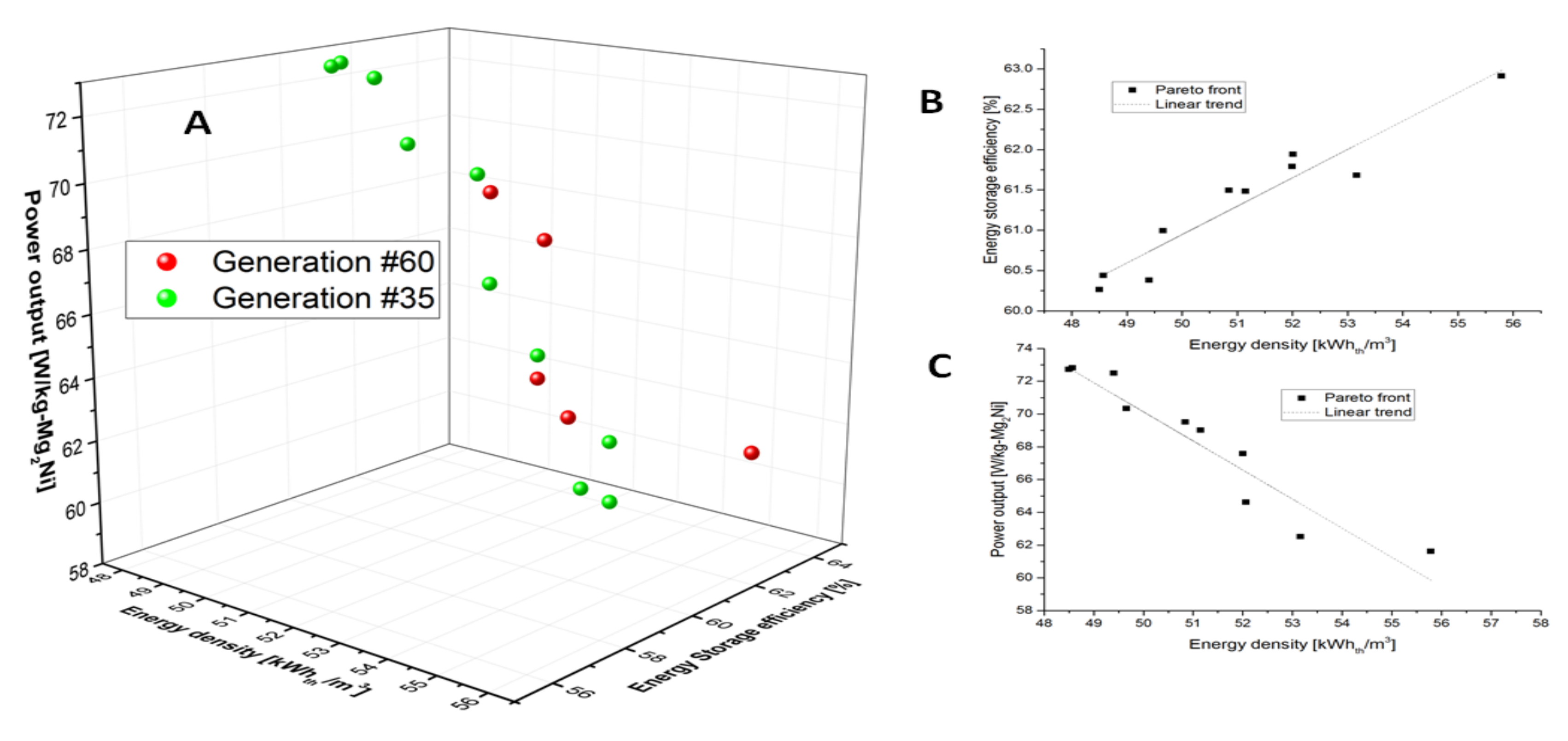
Figure 6A illustrates the Pareto front comprising of the 10 non-dominated solutions at the 35th and 60th generations. It is noticed that this optimization problem converged around the 36th generation, since more than 50% of the solutions are found in the last generation. As can be seen, 5 solutions out of 10 are the same in the generations 35 and 60.
The Pareto front of the last generation is taken for discussion. As can be seen from the right-hand side of the Figure 6A, the energy density and storage efficiency increase while the specific power density decreases. The energy storage efficiency increases from 60.26 to 62.91%, which is only a 4.36% increase for the solutions range (Figure 6B). Likewise, the energy density increases by 15.02% (48.50–55.79 kWhth/m3) in the same solutions range. However, from Figure 6C, it can be seen that there is a negative linear trend between the energy discharging and the power density, i.e., the power density decreases from 72.8 to 61.61 W/kg-Mg2Ni (say 18.15%) as the energy density increases. There are basically two main design parameters that bring about a conflict between the energy density and specific power output. The first is the PCM thermal conductivity, which is enhanced by adding inert materials as discussed above and in [31]. The second one is the discharging time td, which improves the energy storage during the heat discharging while reducing the power output as per Equation (19).
Although the Pareto front proposes many potential optimal solutions, the selection of one to be implemented is guided by decision-making process tools [45,46] which encompass the TOPSIS, Shannon entropy, LINMAP and Fuzzy methods, etc. However, here we introduce a simple and yet robust statistical analysis that pinpoint the optimal design parameters. It is used to assess the distribution of design parameters inside their ranges. As is known, during the optimization process starting from the baseline design, the design parameters iteratively converge towards the optimal ones. As a result, histograms of each design parameter will portray its distribution with a high frequency (counts) around the optimal value.
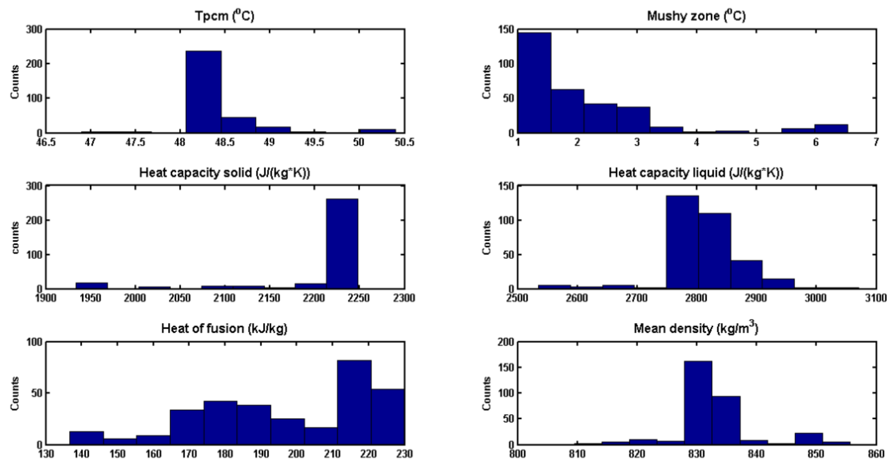
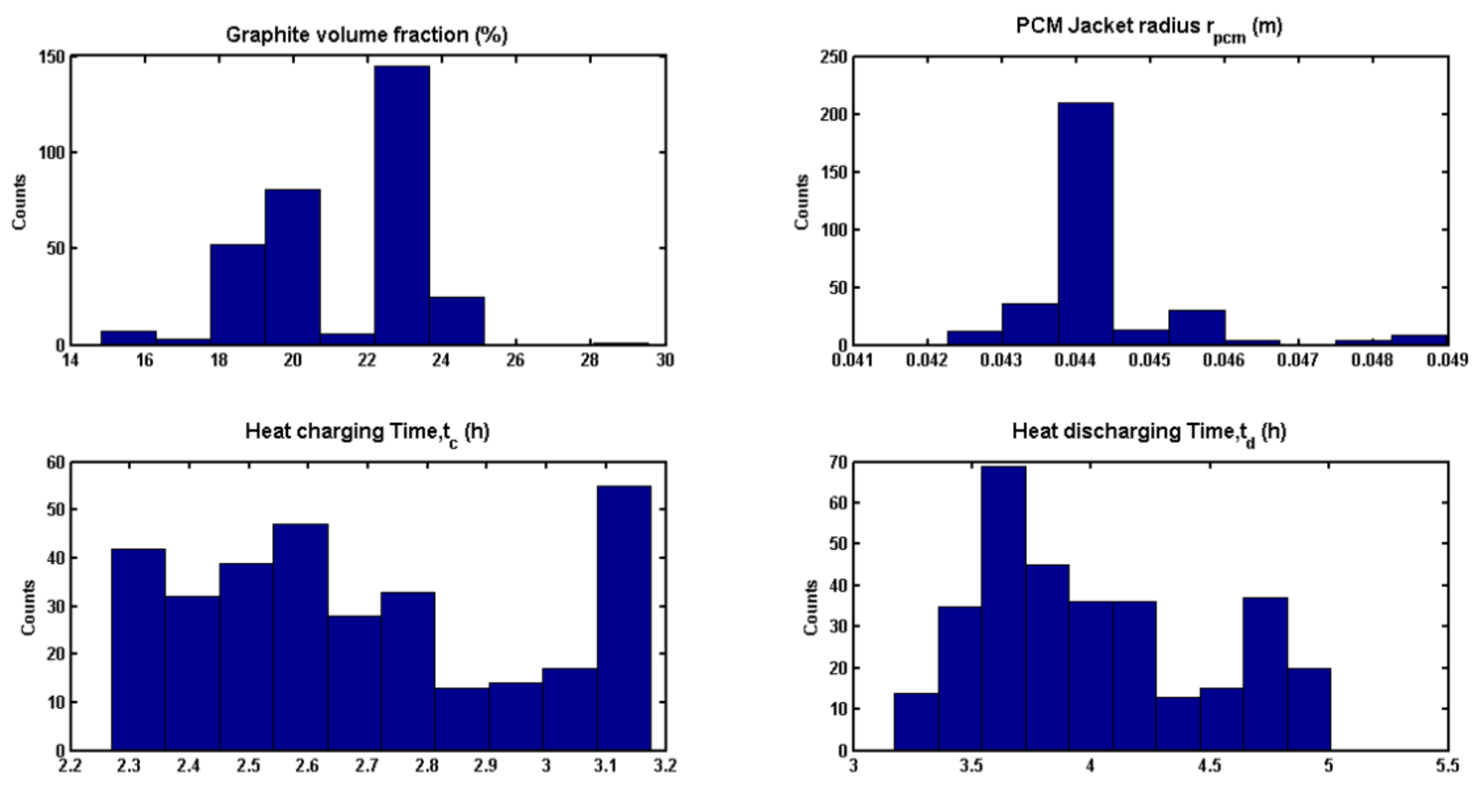
Figure 7 shows the histogram of the optimal PCM properties at the end of the multi-objective optimization process. As can be seen from the figure, the melting point clusters around 48–48.5 °C with a high frequency. This optimum value falls within the range given in Figure 3C. A mushy zone close to 1 °C leads to the optimal design. The solid/liquid heat capacity and the density show relatively high frequency around 2200/2790 J/kg/K and 830 kg/m3, respectively. The latent heat is well distributed in the selected range, which means that this parameter does not have a significant impact on optimal solutions. However, it is observed that latent heat in the range 215–230 kJ/kg has a high frequency. Figure 8 illustrates the statistics of the operating design parameters. Using the same reasoning as previously, the parameter with high frequency is deemed to be the optimal one. The optimum graphite volume fraction clusters around 23%. The histogram of PCM jacket radius shows a high frequency around 0.044 m, which can be considered as the optimum value. However, the heat charging time tc is uniformly distributed on its range. This suggests that it does not play a major role in the optimization process. In contrast, the heat discharging time, td, receives a localized distribution in the narrow range of 3.6–4 h.
Based on the discussion above, the optimal design parameters are listed in Table 4 and their performance is compared to that of RT35 which was the baseline case. As can be seen from the table, the heat storage system using RT35 has an energy density, power density and energy storage efficiency of 15.17 kWhth/m3, 30.8 W/kg-Mg2Ni and 19.69%, respectively. On the other hand, the system performance using the optimized design parameters shows significant improvement. The power density increased by more than two folds, while the energy density and storage efficiency tripled in comparison to the baseline case.

4. Conclusions

In this study, the performance of two-tank metal hydrides based thermal energy storage systems for high-temperature waste heat recovery was numerically investigated. The system consisted of a pair of Mg2Ni/LaNi5 metal hydrides. The integration of PCM for the internal heat recovery of the LaNi5 heat of reaction was proposed and analyzed. The analysis shows that the performance depends intimately on the thermo-physical properties of the selected PCM, the size of the system and the operation duration. The main conclusions are drawn:
  • The melting point of the PCM should be located in the range defined by the maximum/minimum operating temperatures of the LTMH bed. However, the energy density and power output increase with the increases in melting point up to 45–48 °C then fall thereafter. This is because, at that melting point, the thermodynamic driving force of the reaction between beds is the same during heat charging and discharging processes.
  • For a given melting point, the decrease in freezing point by 1–5 °C adversely impacts the heat discharging performance by a maximum of 8%.
  • The PCM thermal conductivity enhancement with the addition of different proportions (2, 5, 10, 15 and 20%) of graphite shows a significant improvement (As high as 23%) compared to the case of plain PCM. Moreover, a graphite fraction of 10% was considered as an optimum value, since beyond that, no significant performance improvement was observed.
A multi-objective optimization of the performance indexes clearly emphasized the tradeoff between the energy density and the power density. Moreover, the results showed that the selected optimized system has the following performance indexes: 67.8 W/kg-Mg2Ni, 50.16 kWhth/m3 and 61.75% for power density, energy storage and energy storage efficiency, respectively.

Author Contributions

Conceptualization, S.N.N. and I.T.; methodology, S.N.N., I.T. and M.L.; software, S.N.N., I.T. and M.L.; validation, S.N.N.; formal analysis, S.N.N. and M.L.; writing—original draft preparation, S.N.N.; writing—review and editing, S.N.N., I.T. and M.L. All authors have read and agreed to the published version of the manuscript.

Funding

This research was funded by the Department of Science and Innovation (DSI) in South Africa; project KP6-S02 “Metal Hydride Hydrogen Compressors and Heat Pumps” and EU Horizon 2020/RISE project “Hydrogen fueled utility vehicles and their support systems utilizing metal hydrides—HYDRIDE4MOBILITY, Project Number: 778307.

Acknowledgments

I. Tolj, M. Lototskyy and S. Nyallang Nyamsi acknowledge financial support from EU Horizon 2020/RISE project “Hydrogen fueled utility vehicles and their support systems utilizing metal hydrides HYDRIDE4MOBILITY” (project number: 778307).

Conflicts of Interest

The authors declare no conflict of interest.

Nomenclature

ASurface area/m2Greek symbols
CpSpecific heat capacity/J kg−1 K−1AReacted fraction
EActivation energy/J mol−1ΔFin thickness/m
hConvective heat transfer coefficient/W m−2 K−1ΕPorosity, Effectiveness/-
HTFHeat transfer fluidHThermal Efficiency/-
HTMHHigh temperature metal hydrideΦVolume fraction/-
ΔHReaction heat/J mol−1 H2ΛThermal conductivity/W m−1K−1
kReaction rate constant/s−1µDynamic viscosity, Pa s
KPermeability/m2ρDensity/kg m−3
LReactor length/mSubscripts
LTMHLow temperature metal hydrideaAbsorption
MMolecular weight/g mol−1ccharging
pPressure/bardDesorption/discharging
PCMPhase change materialeqEquilibrium
QThermal energy/kWhtheffEffective
rRadius, Radial coordinate/mfFluid, PCM freezing
RgUniversal gas constant/J mol−1 K−1gHydrogen gas
ΔSEntropy change/J mol−1 K−1iinlet
tTime/sHHydrogen
ΔTTemperature range of phase transition/KMHMetal hydride
VVolume/m3, hydrogen velocity/m s−1wallReactor wall
wtHydrogen weight fraction/%

References

  1. Miró, L.; Gasia, J.; Cabeza, L.F. Thermal energy storage (TES) for industrial waste heat (IWH) recovery: A review. Appl. Energy 2016, 179, 284–301. [Google Scholar] [CrossRef] [Green Version]
  2. Singh, D.V.; Pedersen, E. A review of waste heat recovery technologies for maritime apiplications. Energy Convers. Manag. 2016, 111, 315–328. [Google Scholar] [CrossRef]
  3. Bademlioglu, A.H.; Canbolat, A.S.; Yamankaradeniz, N.; Kaynakli, O. Investigation of parameters affecting organic rankine cycle efficiency by using Taguchi and ANOVA methods. Appl. Therm. Eng. 2018, 145, 221–228. [Google Scholar] [CrossRef]
  4. Varga, Z.; Palotai, B. Comparison of low temperature waste heat recovery methods. Energy 2017, 137, 1286–1292. [Google Scholar] [CrossRef]
  5. Yamankaradeniz, N.; Bademlioglu, A.H.; Kaynakli, O. Performance assessments of an organic Rankine cycle with internal heat exchanger based on exergetic approach. J. Energy Resour. Technol. 2018, 140, 102001–102008. [Google Scholar] [CrossRef]
  6. Wang, T.; Luan, W.; Wang, W.; Tu, S.T. Waste heat recovery through plate heat exchanger based thermoelectric generator system. Appl. Energy 2014, 136, 860–865. [Google Scholar] [CrossRef]
  7. Yu, X.; Li, Z.; Lu, Y.; Huang, R.; Roskilly, A.P. Investigation of organic Rankine cycle integrated with double latent thermal energy storage for engine waste heat recovery. Energy 2019, 170, 1098–1112. [Google Scholar] [CrossRef] [Green Version]
  8. Magro, F.D.; Jimenez-Arreola, M.; Romagnoli, A. Improving energy recovery efficiency by retrofitting a PCM-based technology to an ORC system operating under thermal power fluctuations. Appl. Energy 2017, 208, 972–985. [Google Scholar] [CrossRef]
  9. Gopal, K.N.; Subbarao, R.; Pandiyarajan, V.; Velraj, R. Thermodynamic analysis of a diesel engine integrated with a PCM based energy storage system. Int. J. Thermodyn. 2010, 13, 15–21. [Google Scholar]
  10. Wang, W.; Guo, S.; Li, H.; Yan, J.; Zhao, J.; Li, X.; Ding, J. Experimental study on the direct/indirect contact energy storage container in mobilized thermal energy system (M-TES). Appl. Energy 2014, 119, 181–189. [Google Scholar] [CrossRef]
  11. Guo, S.P.; Zhao, J.; Wang, W.L.; Yan, J.Y.; Jin, G.; Wang, X.T. Techno-economic assessment of mobilized thermal energy storage for distributed users: A case study in China. Appl. Energy 2017, 194, 481–486. [Google Scholar] [CrossRef]
  12. Guo, S.; Liu, Q.; Zhao, J.; Jin, G.; Wu, W.; Yan, J.; Li, H.; Jin, H. Mobilized thermal energy storage: Materials, containers and economic evaluation. Energy Convers. Manag. 2018, 177, 315–329. [Google Scholar] [CrossRef]
  13. Yan, T.; Wang, R.Z.; Li, T.X.; Wang, L.W.; Fred, I.T. A review of promising candidate reactions for chemical heat storage. Renew. Sustain. Energy Rev. 2015, 43, 13–31. [Google Scholar] [CrossRef]
  14. Jarimi, H.; Aydin, D.; Yanan, Z.; Ozankaya, G.; Chen, X.; Riffat, S. Review on the recent progress of thermochemical materials and processes for solar thermal energy storage and industrial waste heat recovery. Int. J. Low-Carbon Technol. 2019, 14, 44–69. [Google Scholar] [CrossRef] [Green Version]
  15. Yu, N.; Wang, R.Z.; Wang, L.W. Sorption thermal storage for solar energy. Prog. Energy Combust. Sci. 2013, 39, 489–514. [Google Scholar] [CrossRef]
  16. Li, T.X.; Xu, J.X.; Yan, T.; Wang, R.Z. Development of sorption thermal battery for low-grade waste heat recovery and combined cold and heat energy storage. Energy 2016, 107, 347–359. [Google Scholar] [CrossRef]
  17. Li, T.X.; Wu, S.; Yan, T.; Wang, R.Z.; Zhu, J. Experimental investigation on a dual-mode thermochemical sorption energy storage system. Energy 2017, 140, 383–394. [Google Scholar] [CrossRef]
  18. Gao, P.; Wang, L.W.; Wang, R.Z.; Zhang, X.F.; Li, D.P.; Liang, Z.W.; Cai, A.F. Experimental investigation of a MnCl2/CaCl2-NH3 two-stage solid sorption freezing system for a refrigerated truck. Energy 2016, 103, 16–26. [Google Scholar] [CrossRef] [Green Version]
  19. Jiang, L.; Wang, L.W.; Wang, R.Z.; Zhu, F.Q.; Lu, Y.J.; Roskilly, A.P. Experimental investigation on an innovative resorption system for energy storage and upgrade. Energy Convers. Manag. 2017, 138, 651–658. [Google Scholar] [CrossRef] [Green Version]
  20. Sharma, R.; Anil Kumar, E. Study of ammoniated salts based thermochemical energy storage system with heat up-gradation: A thermodynamic approach. Energy 2017, 141, 1705–1716. [Google Scholar] [CrossRef]
  21. Mugnier, D.; Goetz, V. Energy storage comparison of sorption systems for cooling and refrigeration. Sol. Energy 2001, 71, 47–55. [Google Scholar] [CrossRef]
  22. Weber, R.; Dorer, V. Long-term heat storage with NaOH. Vacuum 2008, 82, 708–716. [Google Scholar] [CrossRef]
  23. Fopah-Lele, A.; Rohde, C.; Neumann, K.; Tietjen, T.; Rönnebeck, T.; N’Tsoukpoe, K.E.; Osteerland, T.; Opel, O.; Ruck, W.K.L. Lab-scale experiment of a closed thermochemical heat storage system including honeycomb heat exchanger. Energy 2016, 114, 225–238. [Google Scholar] [CrossRef]
  24. N’Tsoukpoe, K.E.; Schmidt, T.; Rammelberg, H.U.; Watts, B.A.; Ruck, W.K.L. A systematic multi-step screening of numerous salt hydrates for low temperature thermochemical energy storage. Appl. Energy 2014, 124, 1–16. [Google Scholar] [CrossRef]
  25. Clark, R.J.; Mehrabadi, A.; Farid, M. State of the art on salt hydrate thermochemical energy storage systems for use in building applications. J. Energy Storage 2020, 27, 101145. [Google Scholar] [CrossRef]
  26. Fernandez, A.G.; Fullana, M.; Calabrese, L.; Palomba, V.; Frazzica, A.; Cabeza, L.F. Corrosion assessment of promising hydrated salts as sorption materials for thermal energy storage systems. Renew. Energy 2020, 150, 428–434. [Google Scholar] [CrossRef]
  27. Bogdanovic, B.; Ritter, A.; Splietho, B. A process steam generator based on the high temperature magnesium hydride/magnesium heat storage system. Int. J. Hydrogen Energy 1995, 20, 811–822. [Google Scholar] [CrossRef]
  28. Reiser, A.; Bogdanovic, B.; Schlichte, K. The application of Mg-based metal hydrides as heat energy storage systems. Int. J. Hydrogen Energy 2000, 25, 425–430. [Google Scholar] [CrossRef]
  29. Nyallang, S.N.; Lototskyy, M.; Tolj, I. Selection of metal hydrides-based thermal energy storage: Energy storage efficiency and density targets. Int. J. Hydrogen Energy 2018, 43, 22568–22583. [Google Scholar]
  30. Sheppard, D.A.; Paskevicius, M.; Humphries, T.D.; Felderhoff, M.; Capurso, G.; Bellosta von Colbe, J.; Dornheim, M.; Klassen, T.; Ward, P.A.; Teprovich, J.A.; et al. Metal hydrides for concentrating solar thermal power energy storage. Appl. Phys. A 2016, 122, 395. [Google Scholar] [CrossRef]
  31. Nyamsi, N.S.; Tolj, I.; Lototskyy, M. Metal hydride beds-phase change materials: Dual mode thermal energy storage for medium-high temperature industrial waste heat recovery. Energies 2019, 12, 3949. [Google Scholar] [CrossRef] [Green Version]
  32. Mellouli, S.; Abhilash, E.; Askri, F.; Nasrallah, S.B. Integration of thermal energy storage unit in a metal hydride hydrogen storage tank. Appl. Therm. Eng. 2016, 102, 1185–1196. [Google Scholar] [CrossRef]
  33. Darzi, A.A.R.; Afrouzi, H.H.; Moshfegh, A.; Farhadi, M. Absorption and desorption of hydrogen in long metal hydride tank equipped with phase change material jacket. Int. J. Hydrogen Energy 2016, 41, 9595–9610. [Google Scholar] [CrossRef]
  34. Lizana, J.; Chacartegui, R.; Barrios-Padura, A.; Valverde, J.M. Advances in thermal energy storage materials and their applications towards zero energy buildings: A critical review. Appl. Energy 2017, 203, 219–239. [Google Scholar] [CrossRef]
  35. Warzoha, R.J.; Weigand, R.M.; Fleischer, A.S. Temperature-dependent thermal properties of a paraffin phase change material embedded with herringbone style graphite nanofibers. Appl. Energy 2015, 137, 716–725. [Google Scholar] [CrossRef]
  36. Yang, X.; Wei, P.; Cui, X.; Jin, L.; He, Y.L. Thermal response of annuli filled with metal foam for thermal energy storage: An experimental study. Appl. Energy 2019, 250, 1457–1467. [Google Scholar] [CrossRef]
  37. Ling, Z.; Chen, J.; Xu, T.; Fang, X.; Gao, X.; Zhang, Z. Thermal conductivity of an organic phase change material/expanded graphite composite across phase change temperature range and a novel thermal conductivity model. Energy Convers. Manag. 2015, 102, 202–208. [Google Scholar] [CrossRef] [Green Version]
  38. Siyabi, I.A.; Khanna, S.; Mallick, T.; Sundaram, S. An experimental and numerical study on the effect of inclination angle of phase change materials thermal energy storage system. J. Energy Storage 2019, 23, 57–68. [Google Scholar] [CrossRef]
  39. Chung, C.A.; Lin, C.S. Prediction of hydrogen desorption performance of Mg2Ni hydride reactors. Int. J. Hydrogen Energy 2009, 34, 9409–9423. [Google Scholar] [CrossRef]
  40. Merlin, K.; Soto, J.; Delaunay, D.; Traonvouez, L. Industrial waste heat recovery using an enhanced conductivity latent heat thermal energy storage. Appl. Energy 2016, 183, 491–503. [Google Scholar] [CrossRef]
  41. Longeon, M.; Soupart, A.; Fourmigué, J.F.; Bruch, A.; Marty, P. Experimental and numerical study of annular PCM storage in the presence of natural convection. Appl. Energy 2013, 112, 175–184. [Google Scholar] [CrossRef]
  42. Deb, K.; Pratap, A.; Agarwal, S. A fast and elitist multiobjective genetic algorithm: NSGA-II. Evolutionary Computation. IEEE Trans. 2002, 6, 182–197. [Google Scholar]
  43. Sarı, A.; Karaipekli, A. Thermal conductivity and latent heat thermal energy storage characteristics of paraffin/expanded graphite composite as phase change material. Appl. Therm. Eng. 2007, 27, 1271–1277. [Google Scholar] [CrossRef]
  44. Ji, H.; Sellan, D.P.; Pettes, M.T.; Kong, X.; Ji, J.; Shi, L.; Ruoff, R.S. Enhanced thermal conductivity of phase change materials with ultrathin-graphite foams for thermal energy storage. Energy Environ. Sci. 2014, 7, 1185–1192. [Google Scholar] [CrossRef]
  45. Hajabdollahi, Z.; Hajabdollahi, H.; Kim, K.C. Heat transfer enhancement and optimization of a tube fitted with twisted tape in a fin-and-tube heat exchanger. J. Therm. Anal. Calorim. 2020, 140, 1015–1027. [Google Scholar] [CrossRef]
  46. Arora, R.; Kaushik, S.C.; Kumar, R.; Arora, R. Soft computing based multi-objective optimization of Brayton cycle power plant with isothermal heat addition using evolutionary algorithm and decision making. Appl. Soft Comput. 2016, 46, 267–283. [Google Scholar] [CrossRef]
Figure 1. Axis-symmetry 2D computational volume.
Energies 13 04216 g001
Figure 2. Model validation against experimental data from [41]: (A) Schematic of the experimental device and operating conditions. (B) Phase Change Material Temperature temporal profile at two selected location in the experimental device.
Energies 13 04216 g002
Figure 3. The effect of melting point on (A) the H2 weight absorbed/desorbed by the Low-Temperature Metal hydride bed. (B) The phase change material (PCM) liquid fraction in the jacket. (C) performance indexes of the heat storage systems.
Energies 13 04216 g003
Figure 4. The effect of hysteresis behavior on the heat storage performance.
Energies 13 04216 g004
Figure 5. The effects of enhancing the PCM thermal conductivity by addition of expanded graphite on (A) the H2 weight absorbed/desorbed by the LTMH bed. (B) the PCM liquid fraction in the jacket. (C) performance indexes of the heat storage systems.
Energies 13 04216 g005
Figure 6. Pareto front of 10 potential optimal solutions: (A) 3D plot of the 3 objective functions. (B) 2D plot of energy storage efficiency as a function of energy density. (C) 2D plot of power output as a function of energy density.
Energies 13 04216 g006
Figure 7. Statistical distribution of PCM intrinsic properties during the optimization process.
Energies 13 04216 g007
Figure 8. Statistical distribution of the operating parameters for the thermal energy storage system.
Energies 13 04216 g008
Table 1. The main thermophysical parameters of the materials used in the calculations.
Mg2NiLaNi5SS316LGraphite
Heat of reaction/kJ/mol64.530--
Entropy change/J/mol/K122.5108--
Activation energy, abs-des/kJ/mol52.20/63.4621.17/16.47--
Rate constant, abs-des/s−1175/5452.259.18/9.57-
Density/kg/m33200840079902200
Specific heat/J/kg/K697419500710
H2 capacity/wt.%3.61.3--
Effective thermal conductivity/W/mK1116.225
Bed thickness/m0.0150.0150.002-
Reactor volume/m34.948 × 10−44.948 × 10⁻⁴--
Overall heat transfer coefficient hoil/W/m2/K500---
Table 2. The baseline thermophysical parameters of paraffin-based PCM extracted from [33,34,41].
Rubitherm PCM (RT35)Range
Melting point range Tm/°C3530–55
Hysteresis behavior Tm-Tf/°C00,1,2,3,4,5
Mushy zone ΔTtr/°C11–20
Density: solid-liquid/kg m−3880760–2000
Effective thermal conductivity/W m−1 K−11-
Specific heat, Cp/J kg−1 K−120001800–3000
Latent heat of fusion, ∆Hpcm/kJ kg−1165110–230
Volumetric energy density/MJ m−3145-
PCM jacket radius/m0.040.035–0.07
PCM jacket length Lpcm/m0.52-
Graphite fraction, φ E G /%-0–30
Table 3. The maximum H2 exchanged between beds and thermodynamic driving force of the reaction calculated as the ratio of equilibrium pressure of metal hydride beds, during the heat charging (Tc = 350 °C, P e q , H T M H T c = 9.44 bar) and discharging process (Td = 300 °C,   P e q , H T M H T d = 3.18 bar).
Melting Point Tm (°C)Peq,LTMH(Tm)(bar)Heat Charging ProcessHeat Discharging Process
Thermodynamic Driving Force:
P e q , H T M H T c P e q , L T M H T m
Maximum H2 Exchanged (g)Thermodynamic Driving Force:
P e q , L T M H T m P e q , H T M H T d
Maximum H2 Exchanged (g)
302.953.220.490.9275.27
353.582.6320.251.127.97
404.312.1919.821.3511.08
455.171.8217.901.6213.35
485.741.6416.241.8013.14
506.161.5315.091.9312.41
Table 4. Performance comparison between the baseline case and optimized design.
Design ParametersBaseline Design (RT35)Optimized Design
Melting point Tm (°C)3548.25
Mushy zone ΔT (°C)11.15
Heat capacity Cps(J/kg/K)20002200
Heat capacity Cpl(J/kg/K)20002700
Latent heat ΔH(kJ/kg)165220
Density, ρpcm(kg/m3)880840
Graphite fraction, φ E G (vol.%)023
Thermal conductivity using Equation (22) (W/mK)0.25.9
Heat charging time, tc (h)22.66
Heat discharging time, td (h)23.60
Performance indexes
Power density (W/kg-Mg2Ni)30.867.48
Energy density (kWhth/m3)15.1750.16
Energy storage efficiency (%)19.6961.75