Abstract
Although the wireless power transfer (WPT) system for electric vehicles (EVs) provides numerous advantages, there is still a low coupling coefficient and the misalignment between the primary coil and the secondary coil needs to be solved. In this paper, the transmission efficiency and transmitted power were calculated based on Series-Series (SS) compensation topology. The coupling coefficient is related to the coil parameters and misalignments. A simulation study was carried out to explore the variation in the coupling coefficient for different coil configurations under different air gaps and coil misalignments. Moreover, the influence of the internal parameters of the square coil on the coupling coefficient was further studied. Finally, this paper discusses the influence of ferrite cores with a square coil on the coupling coefficient. The results of this paper show that designing the optimal internal parameters of the square coil and the ferrite core can increase the coupling coefficient between the coils, which can also provide guidelines for the design and optimization of the magnetic coupling coils for a wireless charging system for electric vehicles.
1. Introduction
In recent years, electric vehicles (EVs) have become more and more popular all over the world, and EVs will reduce environmental pollution and CO2 emission and achieve a high energy efficiency [1,2]. Moreover, the development and improvement of key technologies with respect to batteries and charging infrastructure as well as electric motors and control increase the attractiveness of EVs [3,4,5]. At the same time, the use of EVs as a sustainable and efficient alternative to traditional diesel- and petrol-based vehicles makes the decarbonization of transport possible in the literature [2]. In [3], the authors used a vehicle stock turnover model of the road freight vehicle fleet to assess the role of powertrain electrification in the decarbonization of road freight transport in the case of Japan. A review on EV technology development in key fields, such in the battery, charging, the electronic motor, charging infrastructure, and emerging technology, was shown in a literature study [4]. In order to evaluate the efficiency and associated accuracy of the power train of a light electric vehicle, in [5] the authors verified the feasibility of the back-to-back direct method. Some vehicle to grid (V2G) services, such as reactive regulation, motor starting, and transient conditions of renewable sources, were applied in EVs, which confirmed that this service does not engage the battery or require small amounts of battery charge in [6]. Thus, the EV is suited for such services.
However, a series of problems still have impeded the rapid development of EVs, such as the short cruising range and long charging time [7,8,9]. As an emerging technology, wireless power transfer (WPT) technology has received more and more attention [10,11,12], which contributes to solving the time-consuming charging and short cruising range, so it can charge the battery while running. In addition, compared with traditional charging methods for EVs, WPT technology is not affected by the foreign environment easily, and is safe and flexible. It is clear that an electrified autonomous charging method in the form of completely autonomous, weatherproof, and wireless rapid recharging will provide essential support for humans, by satisfying essential services and needs without the necessity for human contact.
Based on the charging methods of electric vehicles, the wireless charging system can be divided into stationary wireless charging and dynamic wireless charging [13]. However, due to car charging and especially for dynamic charging, vertical and horizontal offset between the primary coil and the secondary coil are inevitable, resulting in a decrease in the coupling coefficient of transmitter coils. It has been shown that the coupling coefficient is an important parameter for WPT systems, as it determines the maximum output power and can have great impact on the system efficiency [14]. In an ideal design, WPT systems have a high tolerance to misalignment. In [15], the authors proposed a Quad D Quadrature (QDQ) coil design to cope with the misalignment toleration concern of the inductive power transfer (IPT) system for the application of electric vehicles. However, they did not consider the influence on the inner side length of the coil. Juan L. Villa et al., in [16], has presented a new approach to misalignment behavior improvement in inductively coupled power transfer systems (ICPT). The authors claimed that a solution for the misalignment has been studied in a series-parallel-series (SPS) topology. It is possible to stabilize the power level until a certain misalignment by varying the capacitance factor. However, the combined effect of different air gaps and misalignment on the coupling coefficient is not considered. In [17], a number of key parameters are determined, including the coil width and position relative to the ferrite, along with the amount of ferrite required in order to further improve the coupling coefficient. In [18,19], most evaluation criteria have shown that there was a significant linear correlation between the air gap and the lateral misalignment. In [20], the authors showed a comparative study of the two types of magnetic structure (circular and rectangular shapes) design and coupling coefficient calculation. In [21,22], two new polarized coupler topologies were proposed, named the DD coil and DDQ coil, respectively. They have a higher coupling coefficient and a greater tolerance for misalignments compared to circular coils. In [23], the authors have studied the approximately square Double D (DD) coupler. In [24], the authors have presented the circular, square, and rectangular coupler.
In this paper, the main objective is to develop a design approach for a SS topology to study the coupling coefficient for differently shaped coil models under different air gaps and misalignments. Four differently shaped coil models have been proposed in this paper, including circle coils, square coils, rectangle coils, and Double D (DD) coils. Moreover, the different coil configurations are analyzed by the finite element method (FEM) according to the effect of vertical misalignment (air gap distance or Z), front and rear misalignment (X), and door-to-door misalignment (Y). Additionally, the internal parameter effects and a magnetic core analysis of the square coil on the coupling coefficient of the WPT system are presented. The structure of this paper is as follows. In Section 2, an SS topology of the WPT system model was selected to analyze the transmission efficiency and transmitted power. In Section 3, four different coil configurations were studied, including circle, square, rectangle, and Double D (DD) coils. Moreover, the coupling coefficients of different coil configurations are analyzed by FEM according to the effect of vertical misalignment (air gap distance or Z), front-to-rear misalignment (X), and door-to-door misalignment (Y). In Section 4, the theoretical value and the simulation value of mutual inductance for the square coil are analyzed and verified. Furthermore, the influence of the internal parameters of the square coil on the coupling coefficient was explored in detail. In Section 5, the effect of differently shaped magnetic cores with coils on the coupling coefficient were compared. Section 6 draws the conclusion of this paper.
2. Mathematical Model Analysis of SS WPT Systems
In a wireless charging system, offset between the primary coil and secondary coil is inevitable. In order to reduce the leakage inductance which is caused by the change in air gap and misalignment, a compensation network is often added to the circuit. There are four basic topologies: S-S topology, S-P topology, P-P topology, and P-S topology. The S-S topology circuit model is selected to study the effect of air gap and misalignment on the output power and transmission efficiency in this paper. Figure 1 shows the series compensation topology in both the primary coil and secondary coil used in a WPT system, which corresponds respectively to the inductance of the primary and the secondary coil. M represents the mutual inductance between the primary coil and secondary coil. In this example, the compensation capacitor is connected in series with the primary coil and the secondary coil.
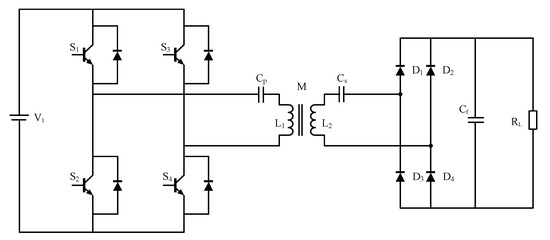
Figure 1.
Circuit diagram of a wireless power transfer (WPT) system.
An equivalent circuit model of a WPT system with compensation capacitors arranged in an SS topology is shown in Figure 1. For simplification, the equivalent source resistance is neglected. Here, the subscripts “1” and “2” refer to the “primary” and “secondary” coil values of inductor L, resistance R, and capacitance C, respectively. V1 is the fundamental sinusoidal component of the source voltage of the primary circuit. RL is the equivalent load resistance of the secondary side converter. I1 is the source current flowing through the primary coil, and I2 is the load current flowing through the secondary coil. Figure 2 shows the equivalent circuit model for an SS topology.
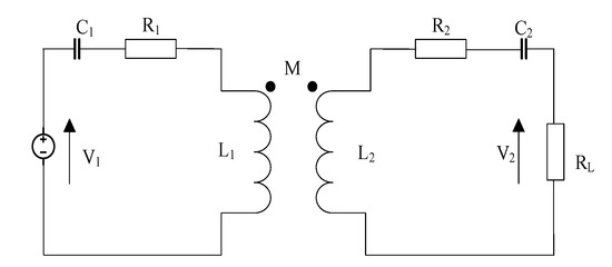
Figure 2.
Equivalent circuit model for a Series-Series (SS) topology.
In Figure 2, the resonant frequency of the WPT system is set to , and the input voltage equation can be written using the mutual inductance, M.
The output power is defined as:
The degree of the coupling between two coils can be expressed with the coupling coefficient k, which has a value ranging from 0 to 1, and is defined by Equation (3). M represents the mutual inductance between the primary and secondary coils.
Then, the output power can be written using the coupling coefficient:
In the wireless charging system, the input power can be described as:
The ratio of the output power of the load terminal or battery sides and the input power of the power source is the transmission efficiency of the wireless charging system. Thus, the transmission efficiency can be calculated as:
From Equations (4) and (6), the coupling coefficient between two coils has a huge impact on the output power and transmission efficiency. However, all the coil parameters have a direct influence on the coupling coefficient of the two coils. These effects reveal themselves not only at different air gaps between the coils but also when there are coil misalignments. Therefore, it is necessary to analyze the relationship between the coupling coefficient and coil misalignments for different coil shapes.
3. Magnetic Coil Configuration Analysis
3.1. Coil Configurations Design
Typical coil shapes of WPT inductors include circular, square, rectangular, and Double D (DD) coil configurations. However, it is not clear if the value of the coupling coefficient can be improved by either of these configurations. Therefore, it is necessary in this section to analyze the performance in terms of the coupling coefficient of different coil configurations. In order to compare the performance of the different coil configurations, the 3D FEM software COMSOL was used. Models of circular, square, rectangular. and Double D (DD) coil configurations without ferrite cores are presented in Figure 3. The air-gap distance is fixed at 100 mm.
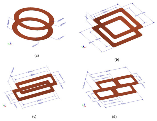
Figure 3.
Diagrams of the different coil models: (a) circular; (b) square; (c) rectangular; (d) Double D (DD).
3.2. Analysis and Simulation of Different Coil Configurations
In this part, the different coil configurations are analyzed by FEM based on the impact on the vertical misalignment (air-gap distance or Z), the front-to-rear misalignment (X), and the door-to-door misalignment (Y). Figure 4 shows the definition for the misalignment in EV.
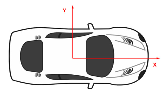
Figure 4.
Two definitions of misalignments in electric vehicles (EV): X-misalignment is the front-to-rear misalignment and Y-misalignment is the door-to-door misalignment [25].
Because of the symmetric geometry of the circular coil and square coil, the simulation results of the X-misalignment and Y-misalignment are same. In the X-misalignment, the coupling coefficient of the circular coil and square coil is near zero when the X-misalignment is 250 mm. Unlike the asymmetric geometry of the rectangular coil and the DD coil, the simulation results of the X-misalignment and Y-misalignment are different. In the X-misalignment, the coupling coefficient of the rectangular coil and DD coil is near zero when the X-misalignment is 600 mm. Whereas, in the Y-misalignment, the coupling coefficient of the rectangular coil and DD coil is near zero when the Y-misalignment is 150 mm. The simulation results are shown in Figure 5, Figure 6 and Figure 7.
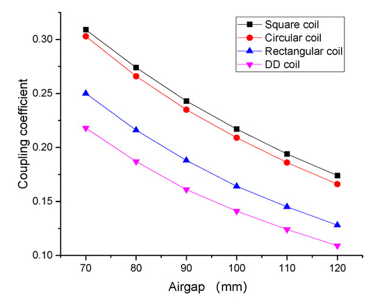
Figure 5.
Coupling coefficient versus the air-gap distance.
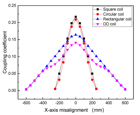
Figure 6.
Coupling coefficient versus the X-axis misalignment.
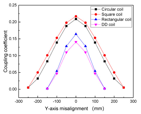
Figure 7.
Coupling coefficient versus the Y-axis misalignment.
In Figure 5, the square coil has a larger mutual inductance than other coil shapes in different air-gap distances. In the X-misalignment, the square coil has a larger mutual value at a smaller misalignment (<100 mm). It only has a small X-misalignment tolerance, which is shown in Figure 6. In the Y-misalignment, the square coil has a good tolerance at Y-misalignment, which is shown in Figure 7. Therefore, a square coil is selected to be analyzed in the next section.
4. Square Coil Design and Verification
In Section 3, it was shown that the square coil has a larger mutual inductance than the other coil shapes, with the same distance between the magnetic coupling coils and the same parameters. In order to further study the factors that influence the mutual inductance of the primary coil and secondary coil, the internal parameters of the square coil were selected as research objectives under the condition of the same area of the windings. For the purpose of studying the influence of the internal parameters on the coupling coefficient, the coupling coefficient is studied at the different air gaps, respectively, 100, 140, and 180 mm.
4.1. Self and Mutual Inductance Calculation
The basic dimensional parameters of such a spiral are N, w, s, dxi, and dxo, as depicted in Figure 8, which are the number of turns, cross-sectional width, spacing between consecutive turns, inner side length of the spiral, and the outer side length of the spiral, respectively.
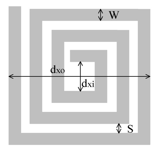
Figure 8.
Diagram of the square coil.
The outer side length dxo is derived from the other geometrical parameters as:
In a square coil, the self-inductance corresponds with [26]:
where:
Considering the primary coil and secondary coil are physically the same, the mutual-inductance can be explained as [27]:
In Equation (11), is the vacuum permeability with a value of H/m, while , . Here, h is the transmission distance.
4.2. Magnetic Square Coil Verification
The mutual inductance value of the square coil at different transmission distances was calculated using Equation (11). Table 1 gives the specific parameter values of the square coil. Table 2 has shown the error of the self-inductance, mutual inductance, and coupling coefficient between the analytical model and FEM model when the air gap is 100 mm. Figure 9 indicates the verification results between the analytical model and the FEM model.

Table 1.
Parameters for the square coil.
Table 2.
Verification parameter of the square coil.
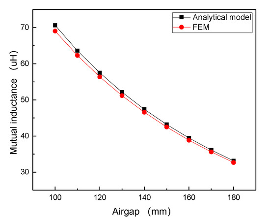
Figure 9.
Mutual inductance versus air gap.
In Figure 9, the error for mutual inductance is biggest when the air gap is 100 mm; it is about 2.3% between the two models. For the analytic model, the differences in mutual inductance happen depending on which algorithms or formulas we used in the model. For the FEM model, the differences in mutual inductance happen depending on which kinds of mesh and solver we used in COMSOL. Because these models are all numerical analysis methods, there may be differences in mutual inductance.
4.3. The Influence of the Internal Parameters for the Square Coil on the Coupling Coefficient
In this section, the square coil was chosen to analyze the influence of the internal parameters on the coupling coefficient under the condition of the same area of winding. The parameters for the square coil are shown in Figure 10.
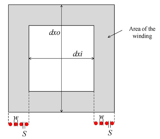
Figure 10.
Diagram of the square coil parameters.
4.3.1. The Influence of the Diameter
In the practical construction of the WPT system, in order to prevent the uneven flow of current in the wire and avoid the skin effect, many Litz wires insulated from each other are used to wind the magnetic coupling structure coil. According to the American wire gauge (AWG) and the actual current in the wireless energy transmission system, the range of 1–5 mm wire diameter variation is selected. The outside length and inside length of the primary coil and secondary coil are fixed values, respectively 330 and 200 mm. The number of turns was kept at 12. The spacing between the consecutive turns of the wire changes with the diameter of the selected wire, which means that when the wire diameter is small, the wire spacing takes a larger value. The simulation results of the influence of the diameter of the wire on the coupling coefficient are presented in Figure 11. According to the simulation, the coupling coefficient of the square coils remains a fixed value basically. Therefore, it can be investigated that the diameter of wire has no influence on the coupling coefficient.
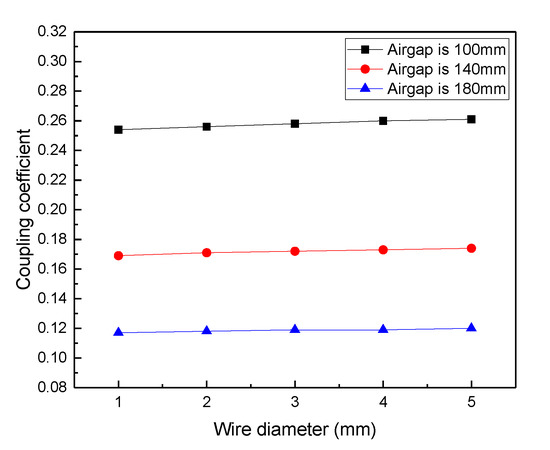
Figure 11.
Coupling coefficient versus wire diameter.
4.3.2. The Influence of the Number of Turns
A similar study is carried out on the number of turns in the coil. At this study, the outside length and inside length of the primary coil and the secondary coil were selected as 330 mm and 200 mm, respectively. In addition, the number of turns of the secondary coil was set 12, and the winding gap was selected as 1 mm. The wires are evenly distributed within the wire winding area, and the number of the turns of the primary coil vary from 10 to 20. The simulation results of the effect of the number of the turns has been shown in Figure 12. It has shown that the coupling coefficient has a small change when the number of coil turns is changed.
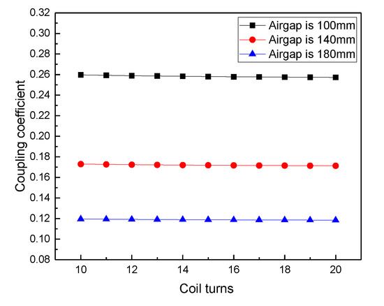
Figure 12.
Coupling coefficient versus the number of turns.
4.3.3. The Influence of the Inner Side Length
The primary and secondary coil designing parameters were kept the same. The outside length of the coil was fixed at 330 mm, the diameter of the wire was chosen to be 2 mm, the spacing between the consecutive turns of the wire was set as 1 mm, and the inside length range of the coil was chosen to be from 182 mm to 272 mm. Figure 13 shows the influence of the inside length on the coupling coefficient for the square-shaped coils. From the results in Figure 13, it can be seen that the coupling coefficient declines when the inner side length of square coil is increased in the range from 180 to 280 mm.
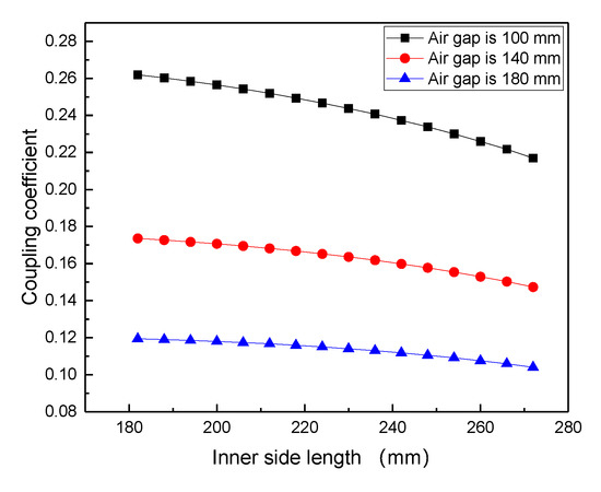
Figure 13.
Coupling coefficient versus the inner side length.
4.3.4. The Influence of the Outer Side Length
As a continuation of the analysis in the previous Section 3, it is necessary to keep the parameters of the secondary coil constant during the simulation. In order to analyze the effects on the outside length, the inside length can be ignored in the analysis. Therefore, the inside length is set 0 mm in the simulation. For example, the inner side length and the outer side length are set as 0 and 260 mm, respectively; the diameter was kept as 2 mm; the gap of windings is kept constant, at 1mm; and the number of coil turns is chosen as 44 turns. On the other hand, the outside length varied from 236 to 404 mm, while the other parameters are kept the same as the secondary coil. The simulation results of the influence of the outside length for the square-shaped coil are shown in Figure 14. It illustrates that the coupling coefficient increases with the increase in the outside length. When it increases to a certain value, the coupling coefficient is increased slowly.
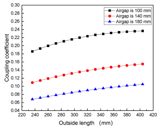
Figure 14.
Coupling coefficient versus the outer side length.
5. Comparative Study of Square Coil with Ferrite Cores
Based on the previous study, it can be confirmed that a reasonable design of the internal dimensions of the coil is beneficial to increase the coupling coefficient between the coils under the condition that the shape of the coil is determined. In order to further improve the coupling coefficient, it is necessary to analyze the effect of the different ferrite cores on the coupling coefficient between the magnetic coupling coils. A 3D view of the only square coil, the square coil with seven ferrite bars, and the square coil with a plane core are shown in Figure 15a–c, respectively. The size of the square coil, ferrite bar, and plane core are shown in Table 3.
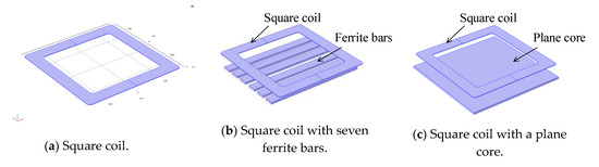
Figure 15.
A 3D view of the square coil with ferrite core.
Table 3.
Parameters for square coil and ferrite core.
Figure 16, Figure 17, Figure 18 and Figure 19 have illustrated the different magnetic field distribution. From these results, it can be concluded that the magnetic core has an effect on the magnetic field, which can effectively reduce the distribution range of the magnetic field.
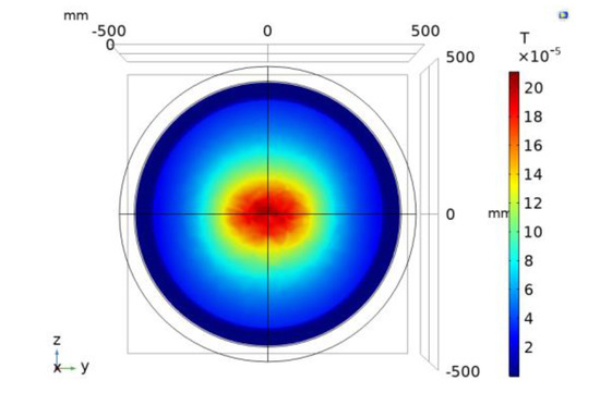
Figure 16.
Square coil.
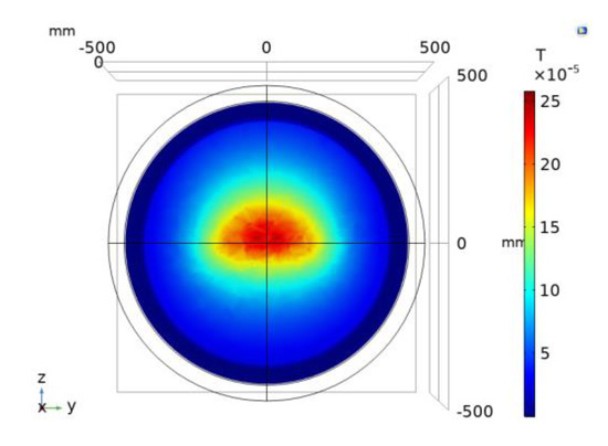
Figure 17.
Square coil with a plane core on the primary side.
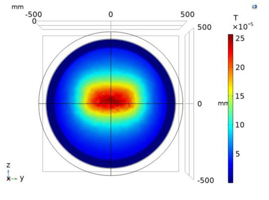
Figure 18.
Square coil with plane cores on the primary side and secondary side.
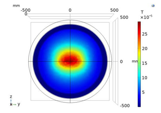
Figure 19.
Square coil with seven ferrite bars on the primary side and secondary side.
Figure 20 illustrates the influence of the different ferrite cores on the coupling coefficient. By comparing the simulation results for the square coils with different ferrite cores, it is revealed that the coupling coefficient between the two coils is higher in the case of the coil with cores on the both sides. Precisely, the coupling coefficient has a highest value, which is about 0.3, corresponding to the square coil with plane cores on the primary and secondary sides. It can be improved 30.4% more than the square coil with no ferrite core.
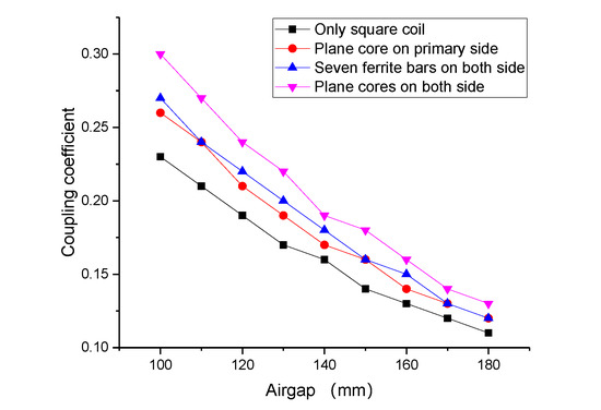
Figure 20.
The effects of the ferrite cores on the coupling coefficient.
6. Conclusions
In this study, the relationship between the coupling coefficient and transmission power and efficiency in a Series-Series (SS) topology WPT system was analyzed. It was highlighted that the coupling coefficient has an important impact on the output power and transmission efficiency. The coupling coefficient is relevant to the shape of the primary and secondary coils as well as the air gap and misalignment between the transmitter coils. Furthermore, the coupling coefficients of differently shaped coils were discussed in detail. In particular, different coil configurations, such as square coil, circular coil, rectangular coil, and DD coil, were modeled and simulated by FEM using the software COMSOL under the conditions of different air gaps and misalignments. It has been shown that for keeping the same area at the primary coil and secondary coil, the square coil provides a higher coupling coefficient than the other shaped coils in the same air gap conditions, with approximately 41.8% more than the DD coil where the air gap is 70 mm. However, the DD coil has a greater anti-offset range when the X-axis misalignment is up to 150 mm. Furthermore, the square coil was chosen to analyze the influence of the internal parameters on the coupling coefficient. The study results revealed that an optimization design of primary and secondary coils is beneficial to improve the coupling ability. Finally, coils with different ferrite cores were compared to a square coil without a ferrite core. The results showed that the coupling ability of the coils with cores was higher than that of the coils without cores. A comparative analysis with no ferrite core was performed and showed that the coupling coefficient for the square coil with plane cores on both sides was improved by about 30%. Therefore, the results have significant impacts on designing a magnetic coupling mechanism.
Author Contributions
Y.Y. performed the modeling, design, and analysis and wrote the original draft and the final version of the paper. J.C. and X.C. contributed to the modeling and the review of the paper and the editing the revision of paper, and J.C. contributed to analyzing the simulation results. J.C. contributed to reviewing and designing the magnetic coil parameters. X.C. contributed to analyzing the results and editing the paper. Y.Y. leads this research as a promoter and edited the manuscript. All authors have read and agreed to the published version of the manuscript.
Funding
This research was funded by the Natural Science Foundation of Shaanxi Province under Grant No. 2020JQ-385 and by the Fundamental Research Funds for the Central Universities, Chang’an University (CHD), under Grant No. 300102220108.
Acknowledgments
We acknowledge the Natural Science Foundation of Shaanxi Province and Chang’an University (CHD) for giving a grant to our research group.
Conflicts of Interest
The authors declare no conflicts of interest.
References
- Mi, C.C.; Buja, G.; Choi, S.Y.; Rim, C.T. Modern Advances in Wireless Power Transfer Systems for Roadway Powered Electric Vehicles. IEEE Trans. Ind. Electron. 2016, 63, 6533–6545. [Google Scholar] [CrossRef]
- Ghosh, A. Possibilities and Challenges for the Inclusion of the Electric Vehicle (EV) to Reduce the Carbon Footprint in the Transport Sector: A Review. Energies 2020, 13, 2602. [Google Scholar] [CrossRef]
- González Palencia, J.C.; Nguyen, V.T.; Araki, M.; Shiga, S. The Role of Powertrain Electrification in Achieving Deep Decarbonization in Road Freight Transport. Energies 2020, 13, 2459. [Google Scholar] [CrossRef]
- Xiaoli, S.; Zhengguo, L.; Xiaolin, W.; Chengjiang, L. Technology Development of Electric Vehicles: A Review. Energies 2020, 13, 90. [Google Scholar] [CrossRef]
- De Santis, M.; Agnelli, S.; Patanè, F.; Giannini, O.; Bella, G. Experimental Study for the Assessment of the Measurement Uncertainty Associated with Electric Powertrain Efficiency Using the Back-to-Back Direct Method. Energies 2018, 11, 3536. [Google Scholar] [CrossRef]
- Ehsani, M.; Falahi, M.; Lotfifard, S. Vehicle to Grid Services: Potential and Applications. Energies 2012, 5, 4076–4090. [Google Scholar] [CrossRef]
- Shekhar, A.; Prasanth, V.; Bauer, P.; Bolech, M. Generic Methodology for Driving Range Estimation of Electric Vehicle with on-Road Charging. In Proceedings of the 2015 IEEE Transportation Electrification Conference and Expo (ITEC), Dearborn, MI, USA, 14–17 June 2015; pp. 1–8. [Google Scholar]
- Maglaras, L.A.; Topalis, F.V.; Maglaras, A.L. Cooperative Approaches for Dynamic Wireless Charging of Electric Vehicles in a Smart City. In Proceedings of the 2014 IEEE International Energy Conference (Energycon 2014), Dubrovnik, Croatia, 13–16 May 2014; pp. 1365–1369. [Google Scholar]
- Wang, Y.J.; Hu, X.H.; Yao, Y.S.; Liu, X.S.; Xu, D.G.; Cai, L.; Hu, B.R.; Hua, K. A Dynamic Wireless Power Transfer System with Parallel Transmitters. In Proceedings of the 2017 IEEE Transportation Electrification Conference and Expo, Asia-Pacific (ITEC Asia-Pacific), Harbin, China, 2–10 August 2017; pp. 146–151. [Google Scholar]
- Yang, L.; Zhang, B.; Ju, M. A Fast Dynamic Response Regulation Method for Undersea Wireless Power Transfer System. In Proceedings of the 2019 14th IEEE Conference on Industrial Electronics and Applications (ICIEA), Xi’an, China, 19–21 June 2019; pp. 1162–1166. [Google Scholar]
- Suh, I.S.; Kim, J. Electric Vehicle On-Road Dynamic Charging System with Wireless Power Transfer Technology. In Proceedings of the IEEE International Electric Machines and Drives Conference (IEMDC), Chicago, IL, USA, 12–15 May 2013; pp. 234–240. [Google Scholar]
- Debbou, M.; Colet, F. Inductive Wireless Power Transfer for Electric Vehicle Dynamic Charging. In Proceedings of the IEEE PELS Workshop on Emerging Technologies—Wireless Power (WoW), Knoxville, TN, USA, 4–6 October 2016; pp. 118–122. [Google Scholar]
- Niculae, D.; Iordache, M.; Stanculescu, M.; Bobaru, M.L.; Deleanu, S. A Review of Electric Vehicles Charging Technologies Stationary and Dynamic. In Proceedings of the 11th International Symposium on Advanced Topics in Electrical Engineering (ATEE), Bucharest, Romania, 28–30 March 2019; p. 4. [Google Scholar]
- Kim, M.; Kim, K.A.; Kim, J.; Jung, J.H. Design Methodology of a 500 W Wireless Power Transfer Converter. In Proceedings of the 2015 IEEE PELS Workshop on Emerging Technologies Wireless Power (WoW), KAIST, Daejeon, Korea, 5–6 June 2015; p. 6. [Google Scholar]
- Kalwar, K.A.; Mekhilef, S.; Seyedmahmoudian, M.; Horan, B. Coil Design for High Misalignment Tolerant Inductive Power Transfer System for EV Charging. Energies 2016, 9, 937. [Google Scholar] [CrossRef]
- Villa, J.L.; Sallan, J.; Osorio, J.F.S.; Llombart, A. High-Misalignment Tolerant Compensation Topology for ICPT Systems. IEEE Trans. Ind. Electron. 2012, 59, 945–951. [Google Scholar] [CrossRef]
- Budhia, M.; Covic, G.A.; Boys, J.T. Design and Optimization of Circular Magnetic Structures for Lumped Inductive Power Transfer Systems. IEEE Trans. Ind. Electron. 2011, 26, 3096–3108. [Google Scholar] [CrossRef]
- Knaisch, K.; Gratzfeld, P. Comparison of Magnetic Couplers for Inductive Electric Vehicle Charging Using Accurate Numerical Simulation and Statistical Methods. In Proceedings of the 2015 5th International Electric Drives Production Conference (EDPC), Nuremberg, Germany, 15–16 September 2015; p. 10. [Google Scholar]
- Prasanth, V.; Bandyopadhyay, S.; Bauer, P.; Ferreira, J.A. Analysis and Comparison of Multi-Coil Inductive Power Transfer Systems. In Proceedings of the 2016 IEEE International Power Electronics and Motion Control Conference (PEMC), Varna, Bulgaria, 25–28 September 2016; pp. 993–999. [Google Scholar]
- Anonymous. Comparative Study on Optimal Core Design for Maximizing the Coupling Coefficient in Electric Vehicle Inductive Power Transfer System. In Proceedings of the International Conference and Exhibition for Power Electronics, Intelligent Motion, Renewable Energy and Energy Management, Nuremberg, Germany, 14–16 May 2013; pp. 1525–1530. [Google Scholar]
- Budhia, M.; Boys, J.T.; Covic, G.A.; Huang, C.Y. Development of a Single-Sided Flux Magnetic Coupler for Electric Vehicle IPT Charging Systems. IEEE Trans. Ind. Electron. 2013, 60, 318–328. [Google Scholar] [CrossRef]
- Budhia, M.; Covic, G.A.; Boys, J.T.; Huang, C.Y. Development and evaluation of single sided flux couplers for contactless electric vehicle charging. In Proceedings of the IEEE Energy Conversion Congress and Exposition (ECCE), Phoenix, AZ, USA, 17–22 September 2011; pp. 614–621. [Google Scholar]
- Nagendra, G.R.; Covic, G.A.; Boys, J.T. Determining the physical size of inductive couplers for IPT EV systems. IEEE J. Emerg. Sel. Top. Power Electron. 2014, 2, 571–583. [Google Scholar] [CrossRef]
- Bosshard, R.; Kolar, J.W.; Muhlethaler, J.; Stevanovic, I.; Wunsch, B.; Canales, F. Modeling and eta-alpha-Pareto Optimization of Inductive Power Transfer Coils for Electric Vehicles. IEEE J. Emerg. Sel. Top. Power Electron. 2015, 3, 50–64. [Google Scholar] [CrossRef]
- Deng, J.J.; Li, W.H.; Nguyen, T.D.; Li, S.Q.; Mi, C.C. Compact and Efficient Bipolar Coupler for Wireless Power Chargers: Design and Analysis. IEEE Trans. Power Electron. 2015, 30, 6130–6140. [Google Scholar] [CrossRef]
- Triviño-Cabrera, A.; González-González, J.M.; Aguado, J.A. Wireless Power Transfer for Electric Vehicles: Foundations and Design Approach; Available online: https://doi.org/10.1007/978-3-030-26706-3 (accessed on 8 June 2020).
- Wenzhou, L.; Jinfei, S.; Chuliang, F. Study of magnetically-coupled resonant wireless power transfer electric car charging system. Electr. Mach. Control. 2016, 20, 46–53. [Google Scholar]


© 2020 by the authors. Licensee MDPI, Basel, Switzerland. This article is an open access article distributed under the terms and conditions of the Creative Commons Attribution (CC BY) license (http://creativecommons.org/licenses/by/4.0/).