1. Introduction
Solar heating of buildings is the main reason for high electricity consumption for air conditioning in tropical and subtropical regions, thus, making solar cooling an especially attractive idea for application in these areas. Normally, solar air conditioning could be accomplished by three means: absorption cycle, desiccant cycle, and solar mechanical cycle [
1]. The solar mechanical cycle might run on two main kinds of energy supply: electricity from a photovoltaic system or mechanical energy from a solar thermal engine. A solar thermal engine would quite often be an external combustion engine, due to its natural compatibility with all kinds of thermal energy as input. In particular, the Stirling engine has been receiving considerable attention in the solar mechanical application field.
A Stirling engine, operating on a closed regenerative thermodynamic cycle, with cyclic compression and expansion of the working fluid at different temperature levels, as described by Walker [
2], relies on internal volume variation caused by repeated heating and cooling of the working fluid and its changing position to produce work output. Being able to approach the ideal cycle efficiency, i.e., the equivalent Carnot cycle efficiency, at designated temperatures with a suitably designed regenerator, along with other features such as low emissions and quietness, a Stirling engine would have great potential for application in residential spaces.
Generally, Stirling engines can be categorized into three types of configuration [
3] as follows:
α-type: this type of configuration features two pistons, each in its own cylinder;
β-type: this type of configuration has a piston and a displacer in the same cylinder;
γ-type: this type of configuration has a piston and a displacer, each in its own cylinder.
A displacer, mentioned above in types 2 and 3, as suggested by its name, aims to produce the displacement of the working fluid from one end to the other and would somehow be similar to a conventional reciprocating piston in behavior. However, while the piston would come with some kind of sealing, a displacer may not necessarily always have such a mechanism as, sometimes, a gap is desired to let the working fluid flow through. Some other displacer designs, such as the rotary displacer [
4,
5], may even go without linear reciprocating motion. In some Stirling engines, the connection between the piston and displacer may not be a solid crank, but rather connected by some springs or even the working gas within. This design is often referred as a free piston Stirling engine.
In addition to the conventional solid mechanical configuration, there is a special category of the free piston Stirling engine, which is sometimes referred as the fluidyne [
2], utilizing a pure liquid to serve as its piston. While mostly used for irrigation applications due to low power density and low operation frequency, the nature of the liquid helps the piston to adapt easily to almost any kind of cylinder configuration with good sealing, without introducing too much friction on the contact surface. Usually, the liquid piston and displacer in a fluidyne would be held in its own U-shaped tubes, while they periodically oscillate within the tubes and operate around the atmospheric pressure. However, the operating pressure conditions may vary due to different design [
6], which suggests a low pressure unit would be possible.
While a heat pipe normally operates under almost constant pressure, there is a category of heat pipes that comes with a pressure control to adjust the operating conditions [
7,
8]. These heat pipes serve situations with a wider range of operating temperatures or, in some cases, contexts with delicate temperature requirements. Some may even operate in conjunction with a Stirling cycle machine for temperature control [
9]. Sowale and Kolios proposed a novel approach to the numerical examination of the quasi-steady model of the gamma-type free piston Stirling engine, including the thermodynamic analysis of the heat exchangers [
10]. Later, the optimization of the second-order quasi-steady model of the gamma-type free piston Stirling engine is performed through a genetic algorithm to maximize performance in terms of power output, and considering the design parameters of components such as piston and displacer damper, geometry of heat exchangers, and regenerator porosity [
11].
Gholamalizadeh and Chung developed a practical methodology which estimates the performance of the solar dish–Stirling system by calculating the performance of each part of the system. A practical example reflected important conclusions regarding the obtained results for thermal losses through the receiver, its thermal efficiency, and the power output [
12].
Shin et al. investigated the energy performance enhancement obtained by applying a heat pump to a liquid desiccant and indirect and direct evaporative cooling-assisted 100% outdoor air system [
13]. A heat pump applied in the liquid desiccant system shown in this research is an adequate solution for the relatively high regeneration energy consumption observed in this system [
13].
2. System Design
A system composed of a Stirling engine with a rotary displacer and an oscillatory liquid piston air conditioning unit, as illustrated in
Figure 1, along with its basic operating principle, is proposed as the focus of this study. The working fluid used in this system is air. We suggest that the whole system should be composed of three parts: the heat source, the Stirling engine, and the air conditioning unit. In this study, the mechanical operating potential of the Stirling engine and the conditioning unit is analyzed and tested experimentally, while the heat source is simulated by a hot water bath electrically heated to the maximum temperature of the temperature profile recorded in field tests, through solar thermal emission collectors modified from a solar water heating system operating in summer conditions. A rotary displacer aims for the capability to adapt the system operating frequency to different working conditions, and the liquid piston pipe is sealed at one end to serve as a pulsating conditioning unit as the piston oscillates within the U-shaped tube.
The displacer chamber is composed of upper and lower plates, and additional fin arrays are installed to increase the heat transfer efficiency. A cylindrical side wall with relatively lower heat conductivity ensures that the energy flow will pass through the working fluid rather than the wall itself. The bulk body of the displacer rotates within the chamber. To control the heat transfer sequence, the end plates should be covered with a heat insulation layer over 240° of their surface, leaving a 120° arc where the fin array is located for heat exchange. The two fin arrays should phase to each other by 60° intervals, as illustrated in
Figure 2, and the displacer bulk should have a 60° notch to contain the working fluid, as shown in
Figure 3.
The liquid piston is housed in a U-shaped tube, which is connected to the displacer chamber at one end and sealed tight at the other. As shown in
Figure 4, the sealed end may have two heat exchange surfaces, with the upper one as the condenser and the lower one as the evaporator. The liquid piston oscillates within the tube, while the liquid head should stay in the region between the condenser and the evaporator. As shown in
Figure 5, when the liquid piston head goes down, the chamber above the piston head at the seal end is enlarged, causing a sudden pressure drop to encourage evaporation of the liquid at the contact surface of the liquid piston and the evaporator section.
Though a small amount of heat absorption in the vapor housing in the upward chamber may reduce the heat absorption effect, this is considered relatively unimportant. When the liquid piston head goes up, the chamber above then decreases in volume, causing a pressure increase to encourage condensation, which thus, rejects the previously absorbed heat out of the conditioning unit. Then, with the cyclic oscillation behavior of the liquid piston, heat absorption and rejection take place alternately, thus, forming a typical piston compression cycle.
3. System Analysis
3.1. Rotary Displacer Analysis
According to Naotsugu Isshiki [
4], the variation of the heat transfer area within a rotary displacer chamber, and even the temperature and pressure profiles, can be approximately simplified into sinusoidal functions. With the nature of the rotary displacer described above, a sinusoidal approximation of the real contact surface area
, whose magnitude is denoted as
, between the displacer cover plates and the gas within is shown in
Figure 6. The effective contact area
is introduced as a sinusoidal function
with a magnitude of
, such that the time integral of the contact area would give the same value as the actual case. Thus,
is defined as follows:
which renders as:
This would suggest a heat flow profile as follows:
where
is the heat transfer amount of the displacer gas;
is the displacer chamber gas temperature;
is the contact area wall temperature;
is the reference rotational velocity, with
the designated time;
is the convection coefficient between the displacer chamber gas and the contact area.
Assuming the displacer chamber gas undergoes the ideal gas behavior, the energy conservation of gas within the displacer chamber would lead to:
where
is the internal energy of the displacer chamber gas, whose mass is
; the work output term is
, with
as the gas constant;
is the molecular mass of the chamber gas, and its specific heat at constant volume
, if the volume variation is relatively small. This gives the relation of the temperature of the displacer chamber gas
and
as follows:
where
and
where
and
are the temperatures of the hot end and cold end, respectively.
Then, the pressure of the displacer chamber gas,
, can be assumed as:
where
and
are the initial pressure and temperature of the chamber gas, with
, the ratio of specific heat at constant pressure to that at constant volume.
3.2. U-Tube Oscillatory Liquid Piston Air Conditioning Unit Analysis
According to Zhang [
6], and defining
x as the displacement of the liquid piston with the upward end at the right-hand side of the tube as positive, then, for the U-shaped tube oscillatory system shown in
Figure 7, the momentum equation would be:
where
is shear stress;
is the density of the liquid;
is the diameter of the tube;
is the pressure in the chamber above the piston;
is the pressure in the displacer;
is the liquid column length.
With the Hagen–Poiseuille law, it could be rearranged as:
where
is the effective kinetic viscosity of the liquid.
With sufficiently long operation time, the liquid piston should behave like a simple harmonic motion system, prompting a displacement of the liquid head as follows:
where
is the initial phase difference between the rotary displacer and the liquid piston phases;
is the vibration magnitude of the liquid piston head. This would render the pressure difference term as:
where
and
As a fair approximation, with a delicate setting of the phase angle, the pressure difference between the piston chamber and the displacer is:
The momentum equation is:
which renders the solution of the piston head as:
This can be simplified as
where
and
are constants determined by the initial condition of vibration. The first term accounts for the effect of the initial vibration condition, by which energy put into the system is eventually dissipated through the damping force, and as the operating time increases, it may become more and more negligible. After a long operating period, then, the motion of the liquid piston is reduced to:
which reconfirms the suggestion from Naotsugu Isshiki [
4,
5].
As to the vapor slug in the upper chamber on the top of the liquid piston, its ideal gas behavior gives:
where
is the original length of the vapor slug in the upper chamber above the piston;
is the mass of the vapor slug;
is the temperature of the vapor slug.
By differentiation with respect to time, this becomes:
Considering the first law of thermodynamics, the related energy equation of the vapor is:
By solving the left-hand term, Equation (22) may be rearranged into:
Substituting Equations (20) and (23) back to Equation (21), replacing the term
leads to:
which can be further revised into:
This suggests an interpretation of the vapor mass
above the liquid piston as:
where
is the integration constant. Its temperature would be readily obtained as:
As the initial conditions may easily be set to
and
, the integration constant
is simply:
With defined in Equation (15), the temperature of the piston chamber gas is readily obtained from Equation (27).
3.3. System Performance Definition
During the experiment, the heat source for the displacer was simulated by an electrically heated hot water bath #1 to simulate the hot water from a solar thermal collector, with its temperature set as the maximum value of the temperature profile acquired from field tests of the performance of solar thermal collectors in summer conditions. The waste heat of the displacer was ejected into another water bath (#2) simulating room temperature water, which would be preheated and go into the hot water tank of the solar water heating system. The two heat exchange surfaces of the U-tube were subjected to water baths at room temperature, in which bath #3 represents the indoor space where the conditioning power would be of use and bath #4 stands for the outdoor space where the heat would be ejected. Each water bath was covered by a heat insulation layer to reduce heat loss. The arrangement of the water baths was as illustrated in
Figure 8.
The performance of the system was evaluated in two parts: the efficiency of the Stirling engine and the coefficient of performance of the conditioning unit (COP).
The efficiency of the engine is defined as:
where
is the available work to power the liquid piston;
is the electrical work to keep the temperature in bath #1 around the initial condition;
is the energy gained in bath #2.
The conditioning unit coefficient of performance could be defined as:
where
is measured by the heat loss from bath #3, which is attached to the evaporator of the conditioning unit, and the work input
is calculated as:
4. Experiment Settings
The whole experiment setup was as shown in
Figure 8, along with the components of the Stirling engine and the oscillatory liquid conditioning unit. The whole inner system was initially vented to a low pressure around 2.3 kPa, which enabled the liquid water to boil at approximately 20 °C. Each section exposed to the atmosphere was covered with a heat insulation layer to reduce interference from outside heat sources, while only the heat exchanging sections would be in contact with the associated water baths. It should be mentioned that the topic of this paper is the prototype design of an oscillatory liquid piston conditioning unit powered by a Stirling engine containing rotary displacer with its cooling capability and compatibility with a conventional solar water heating system. Moreover, in the proposed design, the circumferential fin in rotary displacer as well as the heat absorption and rejection in bath #5 and #6, respectively, have the function of heat exchange through periodic variety of temperatures.
The water loading of each water bath is listed in
Table 1. The electrical heater for bath #1 was set at 200 W, which was able to keep the water temperature in bath #1 at around 85 °C throughout the experiment, which was set as the average maximum temperature according to the field study of solar thermal collectors.
The water temperature in bath #2 was deliberately kept around 27 °C initially, as the same tests suggested that it was the average water temperature before it entered the solar collector if the water supply pipe was embedded within the concrete wall of the building, exposed to the outer atmosphere. The water temperatures in the other two baths were also kept around 27 °C initially to simulate the averaged shielded outdoor and indoor temperature for a room subject to indirect solar emission in a subtropical region, which was also suggested by the tests. The experiment was conducted with a rotary displacer revolving at 0.01, 0.03, 0.05, and 0.1 Hz.
5. Experiment Results and Discussions
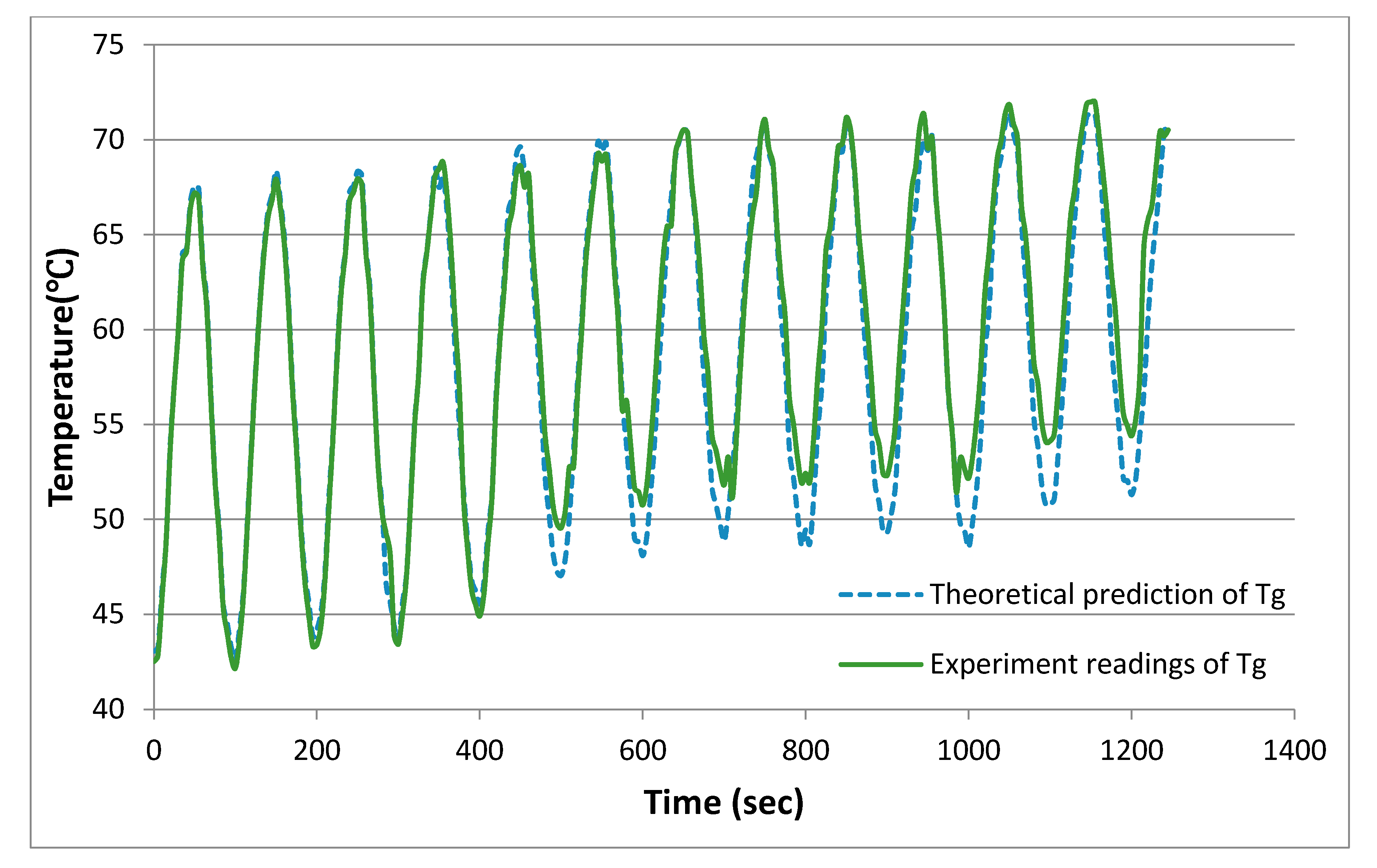
The experimental results suggest that a rotary displacer may serve the purpose effectively, causing a fluctuating variation in the displacer chamber gas temperature profile , throughout the testing range of the operating frequencies. While the heat source, bath #1, was kept at around 85 °C and the heat sink, bath #2, rose from 27 °C to around 40 °C, the temperature of the displacer chamber gas tended to fluctuate by a 15 °C magnitude around the mean temperature between the two baths, which is quite close to the value expected from the prediction of Equation (5) with , using the experimental readings of the contact surface temperature.
Though the illustration in
Figure 9 only shows the result of 0.01 Hz operation, the same tendency is shared in operations at other frequencies. It is a fair guess that for a large enough concentric residential application, due to its constant dispensing of hot water and resupply of cold water, the preheated water, which is intended to serve as the displacer heat sink, may mostly stay at the same temperature. The average value of theoretical prediction and experimental readings of Tg are, respectively, 59.30 and 58.13 °C. The difference of theoretical prediction and experimental readings between the beginning and ending values of Tg are, respectively, 27.91 and 33.25 °C.
A smaller scale application may not always have fresh cold water undergoing the preheating process, so the water from bath #2 would not be returned to bath #1 like the regeneration process used in the present experiments.
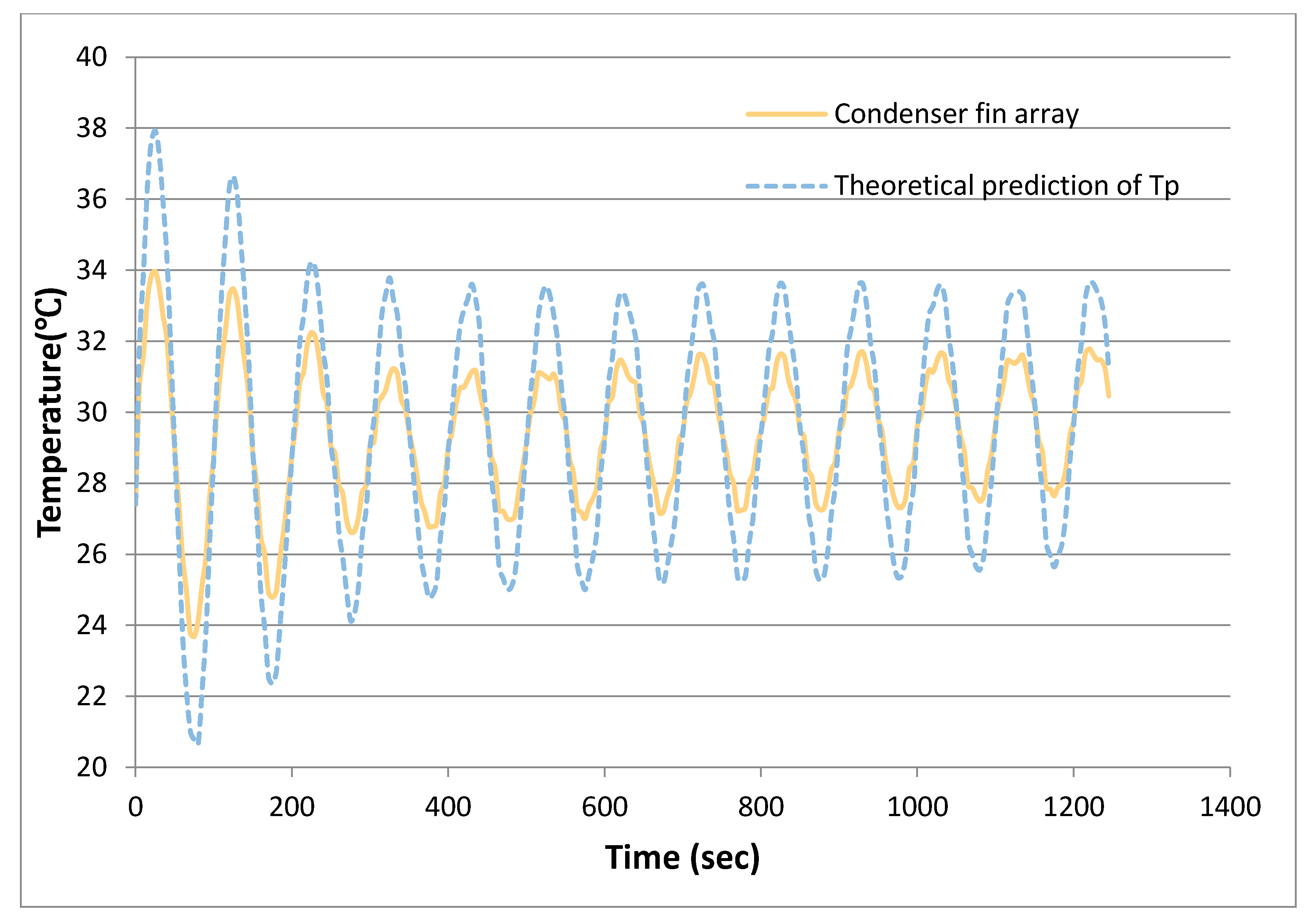
Due to the pipe arrangement and the insulation, the motion of the water heat of the liquid piston may not be directly visible. However, judging from the reading of the fin array at the condenser section, as in the example of 0.01 Hz operation shown in
Figure 10, along with the theoretical prediction from Equation (27), the temperature
should indeed be a cyclic pressure and temperature change within the chamber above the liquid piston, causing heat ejection into water bath #4, as with a conventional piston compressor. The deviation between the theoretical estimate of
and the experimental reading may come from all kinds of loss, especially the friction between the viscous liquid piston and the wall. The average value of theoretical prediction of Tp and condense fin array are, respectively, 29.70 and 29.51 °C. The difference of theoretical prediction of Tp and condense fin array between the beginning and ending values of Tg are, respectively, 3.27 and 3.07 °C.
Table 2 summarizes the system performance under different operating frequencies. The performance of the Stirling engine is evaluated by the efficiency,
. The engine efficiency tended to stay around 5.5%, while the ideal cycle efficiency at the designated temperature conditions might be around 14%, and the waste heat in bath #2 was not yet returned to heating bath #1 to fulfill the regeneration process due to experimental needs.
The cooling capability of the oscillatory liquid piston conditioning unit is evaluated by the temperature drop in bath #3, which represents the indoor space cooled, and the COP of the oscillatory liquid piston air conditioning unit. The COP seemed to rise as the operation frequency increased, but not proportionally. Since the average temperature drops, normalized for 100 s, still tend to rise as the frequency goes higher, the increase in COP may not merely be due to the longer operation time, implying that, although the amount of heat transferred in a single cycle may be lower at higher operating frequency than at lower, it may be compensated by the increased number of cycles. It should be mentioned that, as the example shown in
Figure 10, we take 0.01 Hz operation along with the theoretical prediction. This is because the target area will oscillate with the temperature of each cycle; we average the temperature of each cycle to observe the rising trend of the temperature.
6. Conclusions
An oscillatory liquid piston conditioning unit powered by a Stirling engine with a rotary displacer was designed, prototyped, and tested for its cooling capability and its compatibility with a conventional solar water heating system, using a simulated heat source. The rotary displacer mechanism with the arc fin array conceptually proved operational for the Stirling engine, capable of easy tuning to different operating frequencies to suit the demands of the location.
A further investigation of the potential to operate at higher temperature differences may help to boost the performance. The liquid piston conditioning unit with its COP of 1.3~1.5 could operate like a conventional piston compressor cooler whose COP normally ranges from 1 to 4. However, featuring fewer components and a flexible geometry arrangement, the oscillatory liquid piston conditioning unit may help to reduce maintenance demands.
Author Contributions
C.-S.L. conceived of the proposed idea, designed the experiments and verified the data along with J.-K.L. and H.-T.C. The draft preparation is originally written by the first and corresponding author C.-S.L. The article is mainly revised by C.-S.L., reviewed and edited in part by J.-K.L. All authors have read and agreed to the published version of the manuscript.
Funding
This research was funded in part by Ministry of Science and Technology of Taiwan under the Grant MOST 109-2221-E-020-001.
Acknowledgments
This research was supported in part by Ministry of Science and Technology of Taiwan under the Grant MOST 109-2221-E-020-001. The first author would like to thank Mr. Yi-Hsin Yang, ATECH Totalsolution Co., Ltd., Taiwan, for his assistance in the experimental setup and procedure. The authors wish to thank the anonymous reviewers for their valuable comments and suggestions in revising the paper.
Conflicts of Interest
The authors declare no conflict of interest.
Nomenclature
| maximum value of |
| effective contact area between displacer and gas within |
| real contact surface area between displacer and gas within |
| magnitude of |
| integration constant |
| constant defined in Equation (28) |
| COP | coefficient of performance of the conditioning unit |
| specific heat at constant volume |
| specific heat at constant pressure |
| d | diameter of the liquid piston |
| gravitational acceleration |
| energy flowing into the system |
| heat removed from the system |
| available work |
| waste heat |
| h | convective heat transfer coefficient |
| ratio of |
| L | length |
| M | molecular mass |
| m | mass |
| P | pressure |
| heat transfer amount of the displacer gas |
| R | ideal gas constant |
| T | temperature |
| time |
| U | internal energy |
| W | work |
| work input into the system |
| displacement of the liquid piston |
| vibration magnitude of the liquid piston |
| density vibration magnitude of the liquid piston |
| constant defined in Equation (6) |
| constant defined in Equation (12) |
| efficiency |
| shear stress |
| constant defined in Equation (7) |
| effective kinetic viscosity |
| reference angular velocity |
| , | constants determined by the initial vibration condition |
| rotational angle |
| phase lead of the displacer over the piston |
| angle difference defined in Equation (13) |
| c | the cold end |
| d | the displacer |
| h | the hot end |
| g | the displacer chamber gas |
| p | the piston |
| the wall |
| 0 | the initial condition |
References
- Duffie, J.A.; Beckman, W.A. Solar Engineering of Thermal Processes, 3rd ed.; Johan Wiley & Sons, Inc.: Hoboken, NJ, USA, 2006. [Google Scholar]
- Walker, G.; Senft, J.R. Free Piston Stirling Engine; Springer: Berlin/Heidelberg, Germany, 1985; pp. 235–247. [Google Scholar]
- Cheng, C.H.; Yu, Y.J. Numerical Model for predicting thermodynamic cycle and thermal efficiency of a beta-type Stirling engine with rhombic-drive mechanism. Renew. Energy 2010, 35, 2590–2601. [Google Scholar] [CrossRef]
- Isshiki, N.; Raggi, L.; Isshiki, S.; Hirata, K.; Watanable, H. Regenerative Rotary Displacer Stirling Engine. In Proceedings of the 31st Intersociety Energy Conversion Engineering Conference, Washington, DC, USA, 11–16 August 1996; Volume 2, pp. 1249–1254. [Google Scholar]
- Raggi, L.; Katsuta, M.; Isshiki, N.; Isshiki, S. Theoretical and experimental study on regenerative rotary displacer Stirling engine. In Proceedings of the 32nd Intersociety Energy Conversion Engineering Conference (IECEC), Honolulu, HI, USA, 27 July–1 August 1997; Volume 2, pp. 1017–1022. [Google Scholar]
- Zhang, Y.; Faghri, A.; Shafii, M.B. Analysis of Liquid-Vapor Pulsating Flow in a U-Shaped Miniature Tube. Int. J. Heat Mass Transf. 2002, 45, 2501–2508. [Google Scholar] [CrossRef]
- Wyatt, T. A Controllable Heat Pipe Experiment for the SE-4 Satellite; John Hopkins University, Applied Physics Lab.: Laurel, MD, USA, 1965. [Google Scholar]
- Marcus, B.D.; Fleischman, G.L. Steady-state and Transient Performance of Hot Reservoir Gas-controlled Heat Pipes. In Proceedings of the Space Systems and Thermal Technology for the 70”s, American Society of Mechanical Engineers, Space Technology and Heat Transfer Conference, Los Angeles, CA, USA, 21–24 June 1970. [Google Scholar]
- Anderson, W.G.; Tarau, C. Variable Conductance Heat Pipes for Radioisotope Stirling Systems. In Space Technology and Applications International Forum; Advanced Cooling Technologies, Inc.: Lancaster, PA, USA, 2008. [Google Scholar]
- Sowale, A.; Kolios, A.J. Thermodynamic Performance of Heat Exchangers in a Free Piston Stirling Engine. Energies 2018, 11, 505. [Google Scholar] [CrossRef]
- Sowale, A.; Anthony, E.J.; Athanasios, J. Kolios. Optimisation of a Quasi-Steady Model of a Free-Piston Stirling Engine. Energies 2019, 12, 72. [Google Scholar] [CrossRef]
- Gholamalizadeh, E.; Chung, J.D. Thermal Analysis of the Receiver of a Standalone Pilot Solar Dish–Stirling System. Entropy 2018, 20, 429. [Google Scholar] [CrossRef]
- Shin, J.H.; Park, J.Y.; Jo, M.S.; Jeong, J.W. Impact of Heat Pump-Driven Liquid Desiccant Dehumidification on the Energy Performance of an Evaporative Cooling-Assisted Air Conditioning System. Energies 2018, 11, 345. [Google Scholar] [CrossRef]
© 2020 by the authors. Licensee MDPI, Basel, Switzerland. This article is an open access article distributed under the terms and conditions of the Creative Commons Attribution (CC BY) license (http://creativecommons.org/licenses/by/4.0/).


