Article

Soft Start-Up Control Strategy for Dual Active Bridge Converter with a Supercapacitor

1
Department of Electrical Engineering, Pusan National University, Pusan 46241, Korea
2
Power Conversion and Control Research Center, HVDC Research Division, KERI, Changwon 51543, Korea
*
Author to whom correspondence should be addressed.
Energies 2020, 13(16), 4083; https://doi.org/10.3390/en13164083
Submission received: 15 July 2020 / Revised: 28 July 2020 / Accepted: 5 August 2020 / Published: 6 August 2020
(This article belongs to the Section F: Electrical Engineering)

Abstract

:
Renewable energy needs are steadily on the rise. Bidirectional DC/DC converters are essential in charging and discharging various storage batteries, such as PV/ESS (photovoltaic/energy storage system). A dual active bridge (DAB) converter, in particular, transfers power in both directions by phase shift using a soiled state transformer (SST). To reduce switching inrush current in batteries under high voltages, a soft start-up is demonstrated during the initial switching operation. When a supercapacitor (SC) is used as a battery, the reverse power caused by the inrush current appears under high voltage at the DC-link side. This causes serious electrical damage to the PV/ESS’ boost converter and inverter. To suppress peak overshoot voltage and stabilize soft start-up transients, we propose a three-step soft start-up controller and algorithm for bidirectional DAB converter implementation at virtual ESS and UPS. The step-by-step control strategy by OLDC (open loop duty control), OLPSC (open loop phase shift control), and OLFC (open loop frequency control) provides a stable soft start-up operation. In the initial stage of the OLDC, the duty ratio is gradually increased by the PWM (Pulse width modulation) signal. In the middle stage, a phase difference is seen as per the voltage of the SC. The OLPSC is performed to reduce the phase difference. In the final stage, the OLFC is performed to smoothly control the small phase difference. The overshoot or inrush current is drastically suppressed toward the DC-link and SC module. Consequently, we demonstrate a proposed controller and algorithm with prototype 5 kW DAB converter.

1. Introduction

The demand for PV/ESS has steadily been increasing in recent decades [1]. PV/ESS has many requirements in terms of efficiency, size, and cost. Stable PV/ESS used in homes, buildings, and large power plants is of great importance. The system requires high-power quality and sustainable stability [2]. For stable power conversion, PV/ESS includes a power conversion system (PCS), which is commonly used to convert PV power into commercial power and battery power. It can also provide stable power to batteries and power systems based on various voltage sources, loads, and battery conditions. If this device fails to start or is out of control, it can cause equipment or system damage [3,4,5]. Thus, these devices require various and complex controllers to protect sensitive devices. As shown in Figure 1, a typical PCS applied to this system consists of a boost converter, a bidirectional DC/DC converter, a battery, and a DC/AC inverter. A bidirectional DC/DC converter is required to charge and discharge the battery [6]. In addition, bidirectional DC/DC converters for battery charging and discharging require high efficiency, comprehensive load range operations, wide input and output voltages, and simple circuit topology [7].
A bi-directional H-bridge converter was suggested with high frequency isolation for PV/ESS. Dual active bridge (DAB) converters have been widely used in various renewable devices with high efficiency, high performance, galvanic isolation, and an inherent soft switching function [8,9]. There are two H-bridges in a DAB converter and a single transformer operating in high frequency. One of the H-bridges converts the DC voltage input to high-frequency AC voltage and the other H-bridge converts back the square wave of high-frequency AC voltage to the output DC voltage. The high-frequency transformer with high frequency switching devices has some merits—volume reduction and lightweight passive magnetic devices [10]. Apart from galvanic isolation, there is also an amount of leakage inductance in the high-frequency transformer, in both the primary and second windings [11]. Soft switching is another advantage that is gained by leakage inductance. In addition, power flow of the DAB converter is controlled by changing the phase shift between two H-bridges [12,13,14,15]. The phase change of this manner can adjust the voltage throughout a transformer leakage inductance. The amount of transferring power and the direction of power flow is controlled. From the lagging bridge, power is transferred to the leading bridge. In this regard, the DAB converter is useful in battery application systems such as PV/ESS, UPS, and auxiliary supplies of power for hybrid electric or electric vehicles [16,17,18]. PV/ESS with a DAB converter can also be used for peak load offsets. In regard to energy storage materials, a supercapacitor (SC), also known as an electric double layer capacitor or an ultracapacitor, has attracted considerable attention due to its unique advantages in certain fields compared to the original lithium ion battery [19,20]. SC has developed rapidly in recent years owing to its high electrical stability, high power density, high charge and discharge rate, high conversion efficiency, no chemical reaction, and convenient control [21]. Another merit of SC is their achievement durability. The number of repetitive reversible charges and discharge cycles that they can sustain before performance decay are typically 1000,000 or more. Hence, supercapacitors (SC) can provide a higher power density with respect to batteries [22]. In this case, SC is used in place of lithium-ion batteries that limit instantaneous high power [23,24]. SC has a small capacity, but it has the merits to control high power output [25,26,27]. Therefore, SC is suitable for peak load offsets. IGBT (Insulated gate bipolar transistor) and MOSFET (Metal Oxide Semiconductor FET) components are often damaged due to the high voltage applied to the DAB converter. This problem can be solved by increasing the duty ratio gradually from 0 up to 50% at the initial soft start-up operation of the DAB converter [28,29]. When the SC module is charged and discharged by a DAB converter, it initially performs a soft start-up operation to maintain a stable PWM switching [30]. Unlike lithium-ion batteries, the SC module has a large potential difference during charging and discharging. Unidirectional DC/DC converters such as LLC resonant converters, boost converters, and buck converters are unavailable to transfer power to the DC-link side, depending on frequency and SC module voltage [31,32,33]. However, the bidirectional DAB converter is available to transfer power from the SC module to the DC-link side during the initial soft start-up operation. When the voltage on the DC-link side is rapidly increased, it can cause serious damage to the boost converter and DC/AC inverter [34]. After the soft start-up is over, an excessive phase shift occurs on transition from the transient state to the steady state [35]. Induced inrush currents appear from the IGBTs and MOSFET switches and the SC module [36]. Although it is only for a few seconds, it can cause severe damage to the entire PV/ESS, including the grid and loads [37]. Furthermore, in PV/ESS applications, special technique is needed to increase the stability of the DC-link side, adding the DAB converter at the PCS. In particular, the PCS driven at a high voltage causes a lot of errors in transient state. Therefore, we need to control the reverse power transfer and improve the stability of the transient state. Thus, improved soft start-up controller and algorithm are required to minimize the reverse power transfer and instability of transient state in the DAB converter implementing in PV/ESS application.
In this study, we propose an optimal controller for soft start-up operation in a DAB converter with an SC module. The proposed controller can minimize the inrush current and move voltage forward to the DC-link side. We demonstrate this situation in various operating modes with a 5 kW prototype DAB converter and SC. The concept of soft start-up for a DAB converter are reviewed in Section 2. The proposed soft start-up controller and algorithm are presented in Section 3. Section 4 presents the DAB converter design. Section 5 presents the simulation results. Section 6 presents the experimental setup. Section 7 presents the experimental results and discussion. Finally, the conclusion is given in Section 8.

2. Concept of Soft Start-up for DAB Converter

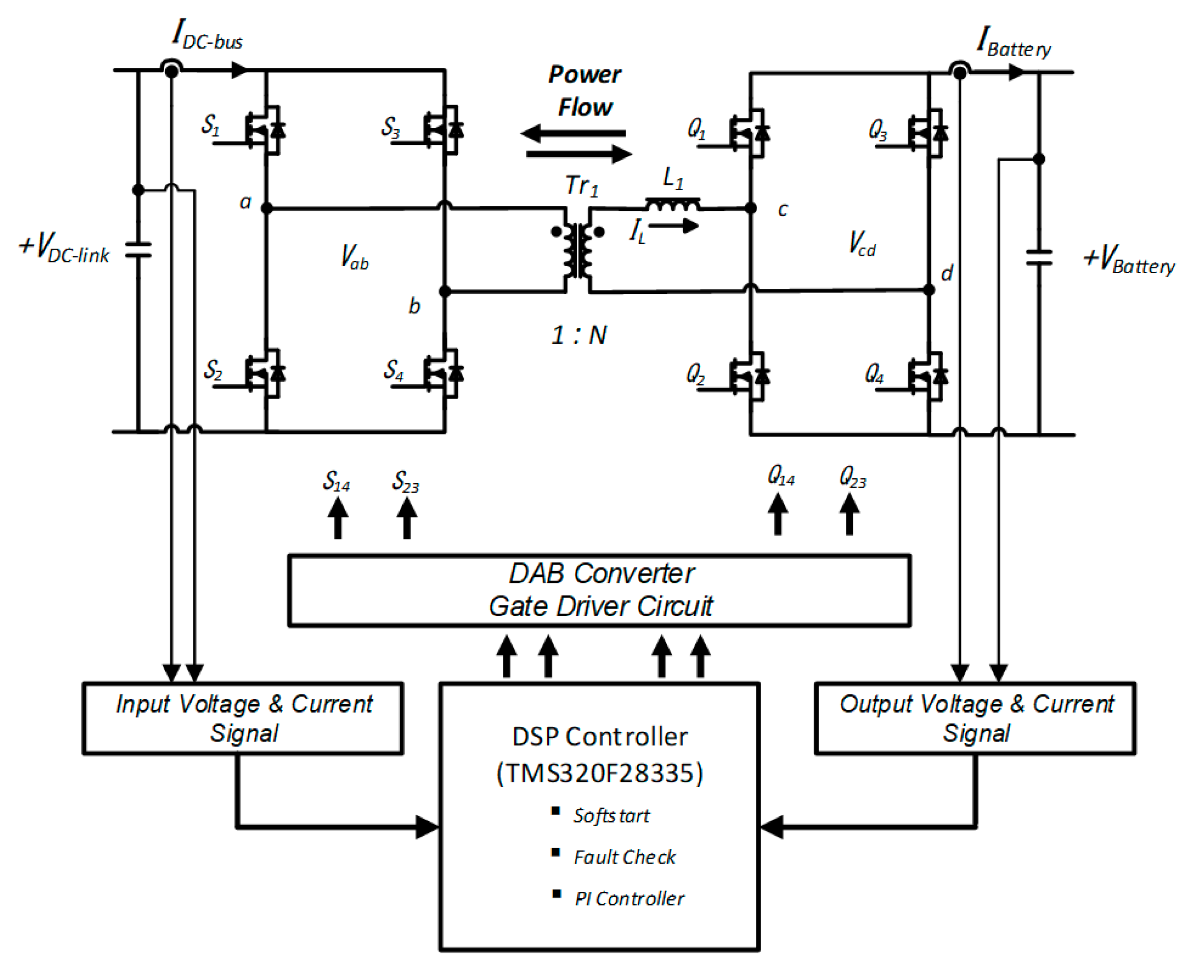
A DAB converter with two H-bridges circuits is connected to the isolation transformer Tr1 and a coupling inductor L1, as shown in Figure 2. The H-bridge on the left side is connected to the DC-link and the H-bridge on the right side is connected to the battery. Each bridge is controlled to provide the DC-link square wave voltage. The two square waves can be suitably phase-shifted with respect to each other to control the power flow from a DC-link to another. The magnitude of the current is determined by the inductance of the coupling inductor. In buck mode, the phase of the Vab square wave is shifted by the phase of the Vcd square wave. Thus, bidirectional power flow is enabled through the transformer and inductor. The power always flows from the bridge of the leading square wave to the other bridge.
In charging mode, the peak to peak change in a coupling inductor current can be found by analyzing the voltage across a coupling inductor L1 over a half cycle. The difference in voltage between the two H-bridges appears across the coupling inductor and the coupling inductor current and voltage changes with constant interval. Expressions are derived for the coupling inductor current at the switching instants IP and IL1 as follows:
I P = T S 4 L [ V b a t t e r y ( 2 d 1 ) + n V D C _ l i n k ]
where, I P is the peak point of inductor current, T s is the switching period, L is the leakage inductance, d is the phase difference, n is the transformer ratio, V b a t t e r y is the voltage of battery, V D C l i n k is the voltage of DC-link.
In a similar manner, IL1 is found to be:
I L 1 = T S 4 L [ n V D C _ l i n k ( 2 d 1 ) + V b a t t e r y ]
where, I L 1 is the second peak point of inductor current.
In order to find the average SC current, an expression is required for the interval tB. The time taken for iL to fall from IP to zero following the Vab switching instant. From Equations (1) and (2), we can simply derive an expression for tB:
t B = T S [ n V D C l i n k + V b a t t e r y ( 2 d 1 ) ] 4 ( n V D C l i n k + V b a t t e r y )
where, t B is the interval from peak current to 0 at coupling inductor.
Using the above equations, the average output current and power at the battery in charging mode is expressed as follows:
I b a t t e r y , a v g = T S n V D C l i n k 2 L ( d d 2 )
where, I b a t t e r y , a v g is the average current of battery.
P o = T S n V D C l i n k V b a t t e r y 2 L ( d d 2 )
where, P o is the output power of battery.
Equation (4) shows the variation of the normalized average output current with duty ratio.
It can be observed from Equation (5) that maximum power transfer is achieved at the phase shift of 90°. Therefore, the maximum average output current occurs at a duty ratio of 0.5.
The transfer energy proceeds from one H-bridge to the other. It can be involved from two different parts: First, the referred high voltage side to the low voltage side from the H-bridge itself. Second, from the coupling inductor, which is in flow of carrying the power and connecting both bridges.
Equations (6) and (7) represent these two parts, respectively:
E d = 0 t B V D C l i n k i L d t
E d = 1 2 L I m i n 2
where, E d is the coupling inductor energy, I m i n is the minimum coupling inductor current.
It replaces this expression in the integral above and derives the increment of the voltage of SCs:
E d = 0 t B V D C l i n k 2 C s d v C s d t d t = 2 V D C l i n k V b a t t e r y C s
where, C s is the snubber capacitance.
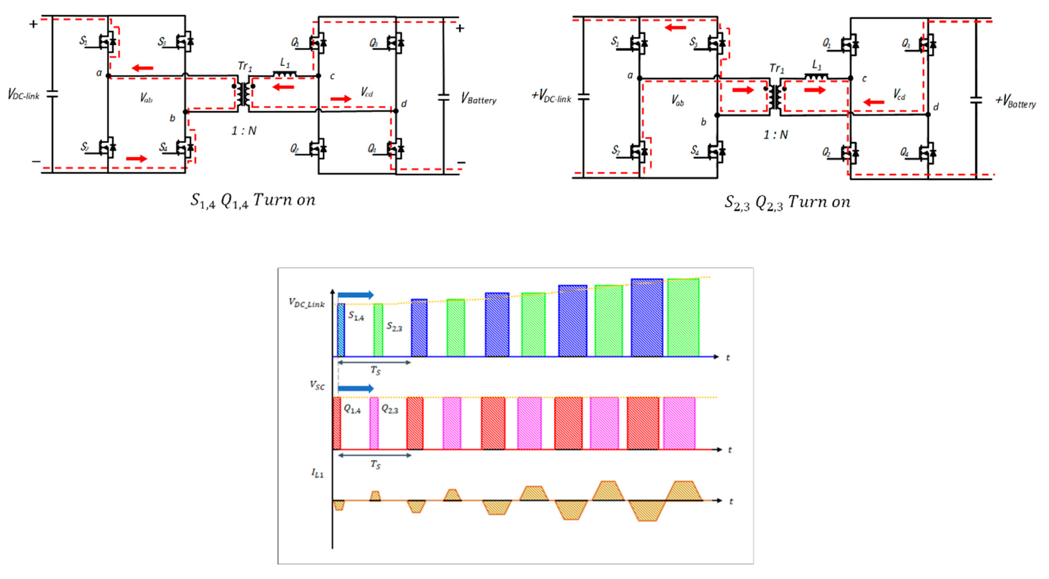
The initial operation sequence of the conventional DAB converter is to use a fixed duty ratio. When voltage of the DC-link and batteries is low, a fixed duty ratio does not cause stress on the switching module. However, the DC-link in PV/ESS occurs at high voltage and directly transfers power to the SCs. It causes inrush current and power loss. To address the problem of damage to the switching module, the DAB converter performs a soft start-up operation before charging or discharging operation. In general, the PWM signal generated in the digital signal processor (DSP) board increases from 0% to 50% duty ratio. In this case, it is possible for the soft start-up operation to reduce inrush current and power loss at the switching module. In PV/ESS, the SC module has a high potential difference for each module. When the voltage of the SC module is low during soft start-up operation, the phase difference between the Vab and Vcd is decreased. Therefore, power flow is suppressed by the phase difference. However, at a high voltage of SC module, reverse power occurs at the final stage of the soft start-up operation through a coupling inductor and fast recover diode (FRD). As the DC-link has low capacitance, it leads to a sharp increase in voltage. Figure 3 shows a current flow diagram and the voltage increase of DC-link at the soft start-up operation. As the initial duty ratio rises quickly, the coupling inductor current and the DC-link voltage sharply increases. There are ways to increase the capacitance of the DC-link stage to suppress the voltage rise, but high inrush currents occur early in the system.
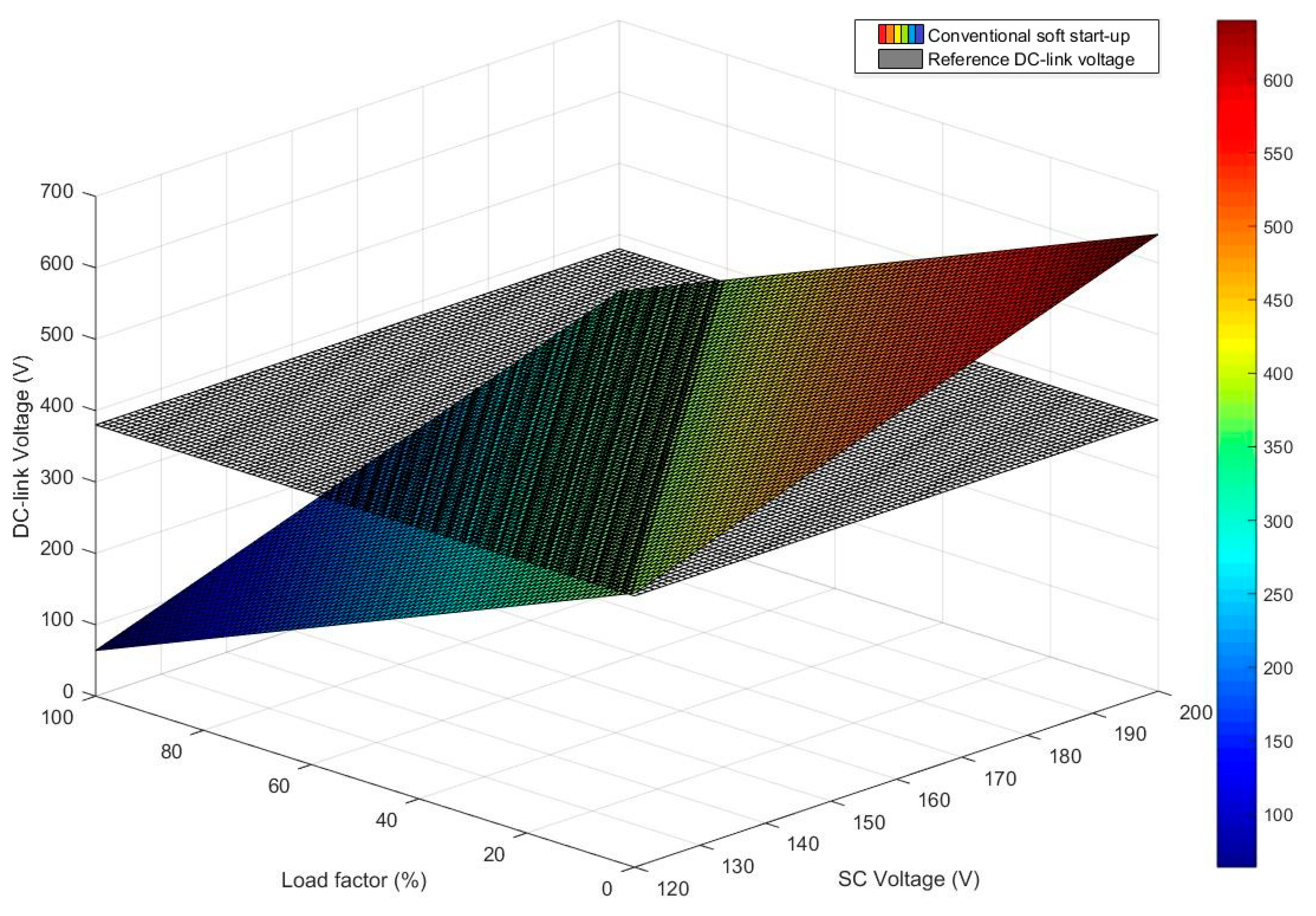
This is not only in charge mode, but also in discharge mode. In discharge mode, a constant high DC-link voltage should be maintained at the soft start-up operation. If the SC module has a high voltage and the DC-link side has a low load or no-load, it could induce a sharp voltage increase in the DC-link. Likewise, when the SC module has a high voltage and the DC-link side has a high load, a low voltage of DC-link could occur, less than that of the reference voltage. Figure 4 shows the DC-link voltage according to load factor and SC module voltage during the soft start-up operation. It shows that the converted voltage may not be reached at reference voltage. This means that optimal controller and algorithm are required to obtain the reference DC-link voltage.

3. Proposed Controller and Algorithm

3.1. Proposed 3-Step Soft Start-up Operation

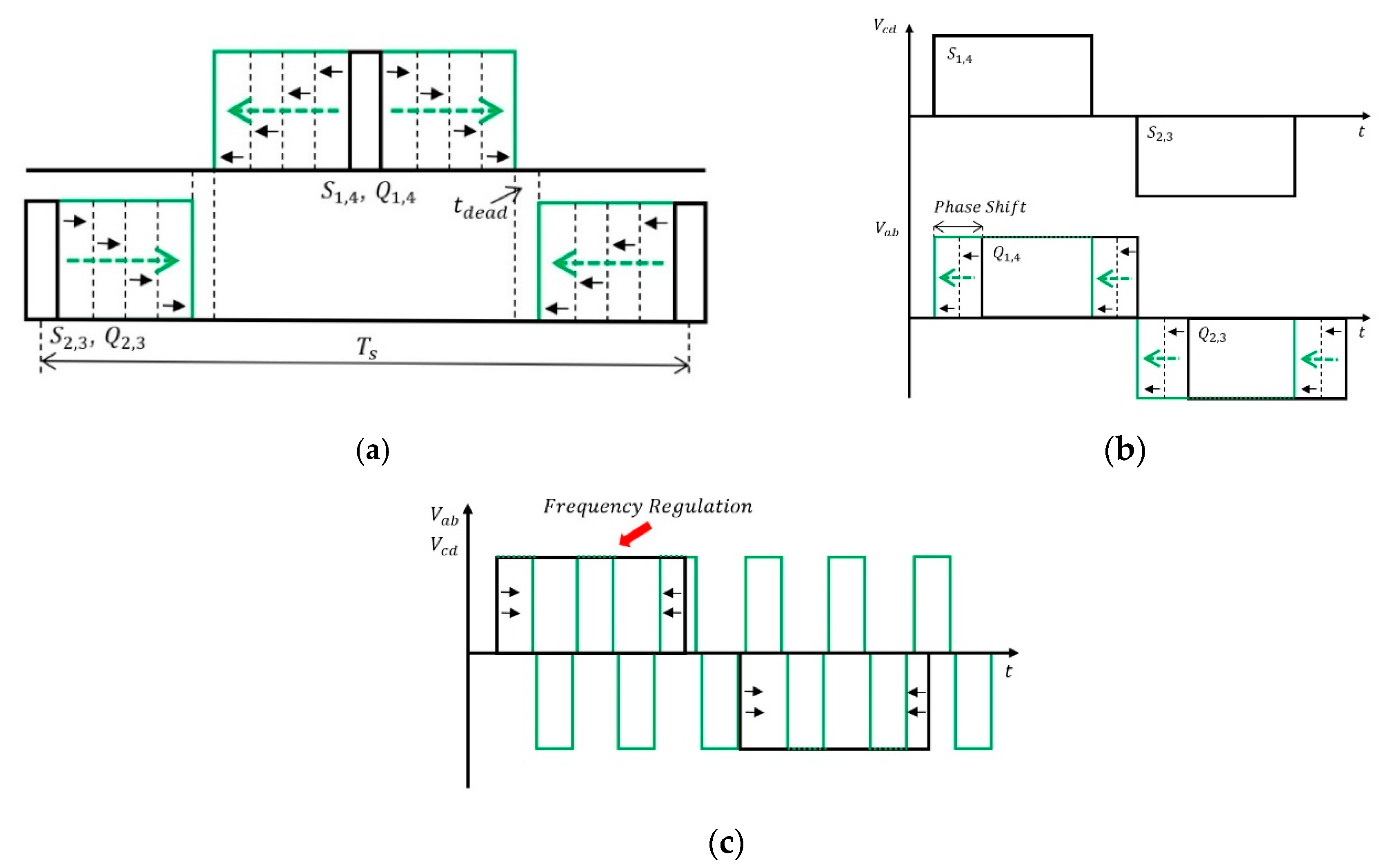
To address the problems of the DC-link voltage increase during the soft start-up operation, improved soft start-up controller and algorithm are proposed. In general, the open loop duty control (OLDC) is applied to reduce the initial inrush current. When the OLDC starts in low SC voltage state, the DC-link voltage stably follows the reference voltage. As a result, there is no power loss. However, due to the high SC voltage, the DC-link voltage may not maintain the reference voltage. Therefore, to suppress the DC-link voltage increase, an open loop phase shift control (OLPSC) is required. The OLPSC is performed with an initial soft start-up operation to suppress DC-link voltage rise and reach the reference power smoothly. However, at the final stage of the soft start-up operation, a slight duty increase in the switching signal causes a large phase shift. In this stage, the DC-link voltage, which applied the OLPSC, is unstable. This is because the phase shift control, as a result of the OLPSC, is unfollowable in an instant.
To reduce the phase difference between the primary and secondary bridges, the open loop frequency control (OLFC) is proposed. Equation (5) confirms that the power of the DAB converter is determined by phase shift and frequency control. The additional frequency control regulates the DC-link voltage by reducing the small phase difference in the final stage. The 3-step (OLDC, OLPSC, OLFC) soft start-up algorithm helps reach the reference voltage of the DC-link. Figure 5 shows the proposed 3-step soft start-up algorithm principle. In the initial stage of the OLDC, the duty ratio is gradually increased by the PWM signal. In the middle stage, the phase difference is shown according to the voltage of the SC. The OLPSC is performed to reduce the phase difference. In the final stage, the OLFC is performed to smoothly control the small phase difference. Improved soft start-up operation takes place in few seconds. This 3-step soft start-up sequence decreases the reverse power and helps achieve the required reference voltage and current at the DC-link. In addition, PI controllers are designed in the OLPSC and OLFC to achieve a proper phase shift gap and switching frequency. During the operation of the OLDC mode, from the point where reverse power occurs, the current PI controller achieves the reference current with the OLPSC.
The required phase shift value is generated by an additional feedback signal, which helps follow the reference current value smoothly and reduces the burden on the controller from the SC voltage value. During the OLPSC operation, the current PI controller that receives a feedback signal from the SC voltage value is expressed as follows:
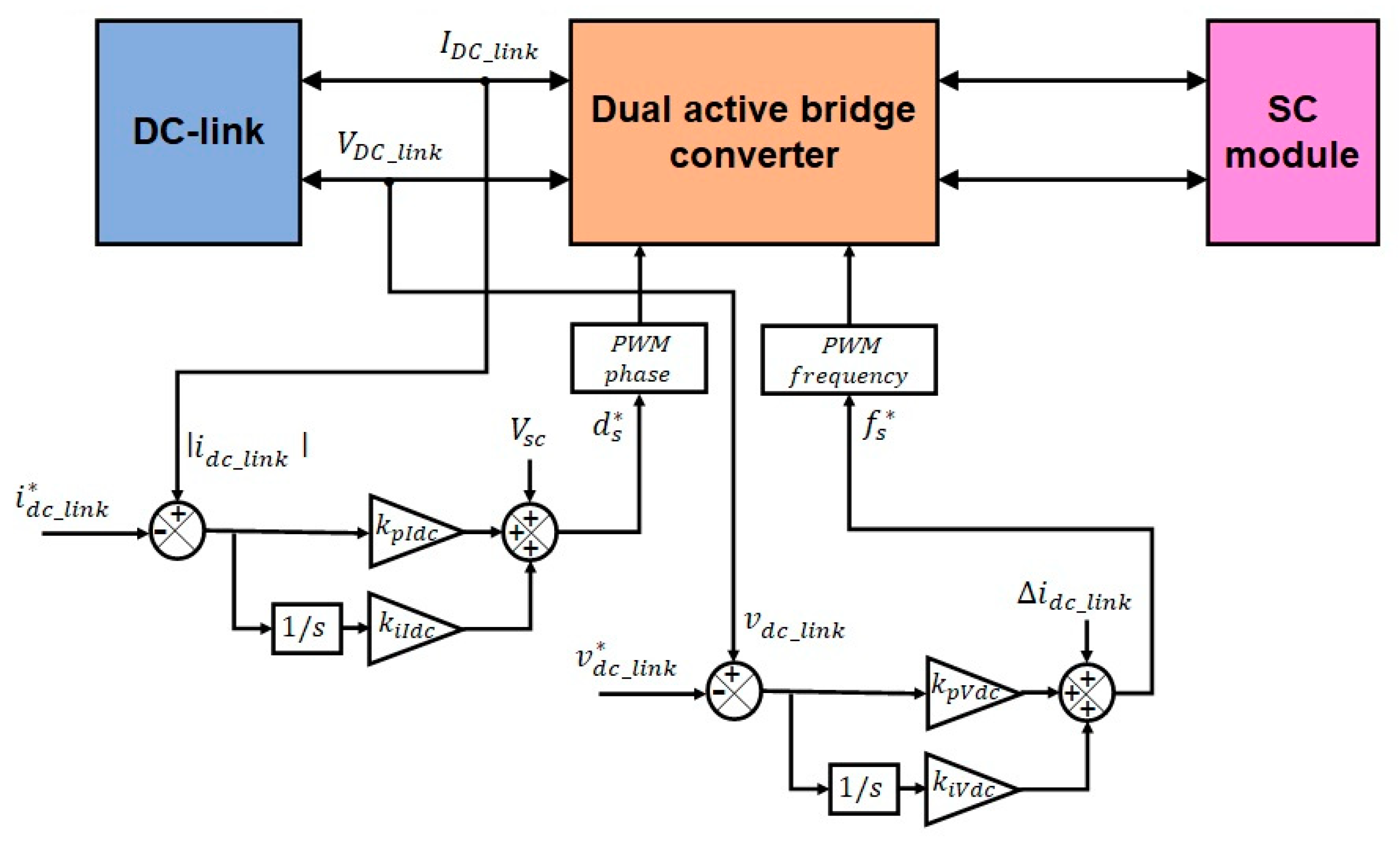
d s * = v s c + k p I d c s + k i I d c s ( i D C l i n k i D C l i n k * )
where v s c is the SC voltage, i D C l i n k is the DC-link current, d s * is the phase shift of primary and secondary square wave. By controlling the DC-link current in grid or stand-alone mode, the DC-link voltage is regulated by the v s c value, which rapidly reduces the current error. As a result, the initial transient response characteristics can be improved.
In the OLFC operation, the DC-link voltage PI control is performed by changing the frequency. This operation is a command to suppress the DC-link voltage rise due to the phase shift rapidly occurring at the final stage. The voltage controller was constructed by reinforcing a compensator of the DC-link current variation to the previous PI controller. The voltage PI controller that receives a feedback signal from the DC-link current variation value is expressed as follows:
f s * = Δ i D C l i n k + k p V d c s + k i V d c s ( v D C l i n k v D C l i n k * )
where   Δ i D C l i n k is DC-link current variation value, v D C l i n k is the DC-link voltage, f s * is the switching frequency. The frequency control value is added by the current variation value and it smoothly follows the DC-link voltage reference. The above two equations contribute to the stable control of the rapidly increasing DC-link voltage. The proposed 3-step soft start-up algorithm is continuously maintained until the operation of charge or discharge mode in the DAB converter. The voltage and current PI controller block diagram for the 3-step soft start-up algorithm is shown in Figure 6.
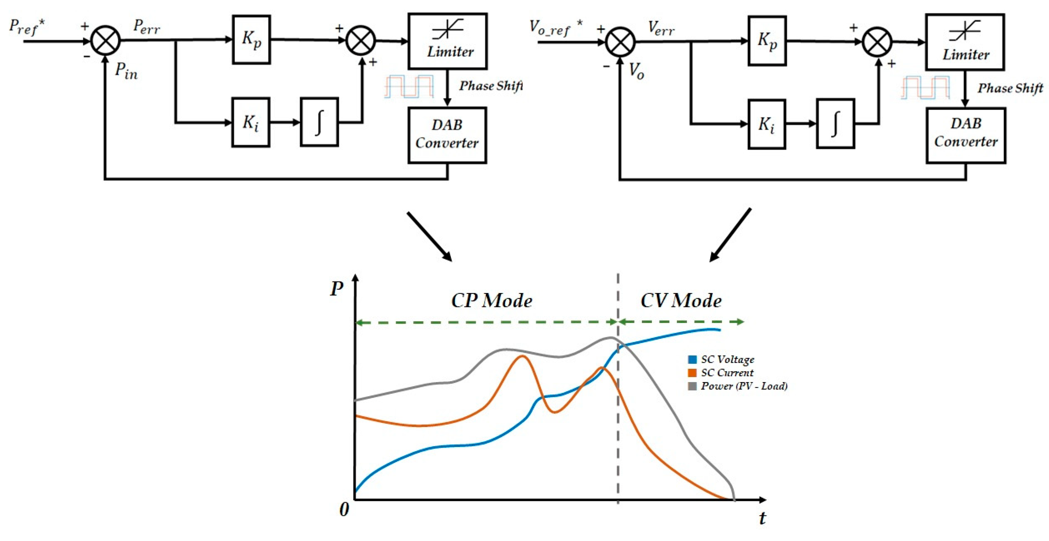
The PI controller switchover occurs when the soft start-up is completed and the DAB converter is switched to charge or discharge mode. In the charge mode, the CP-CV (constant power-constant voltage) controller operates to draw the maximum power point of solar panel. Moreover, the current and voltage reference for SC charging are set by the equal 3-step soft start-up algorithm. Therefore, transient state problems, such as the current and voltage fluctuation, are reduced. Consequently, fast transient and smooth steady state operation is achieved.

3.2. Designed 3-Step Soft Start-up Algorithm for DAB Converter

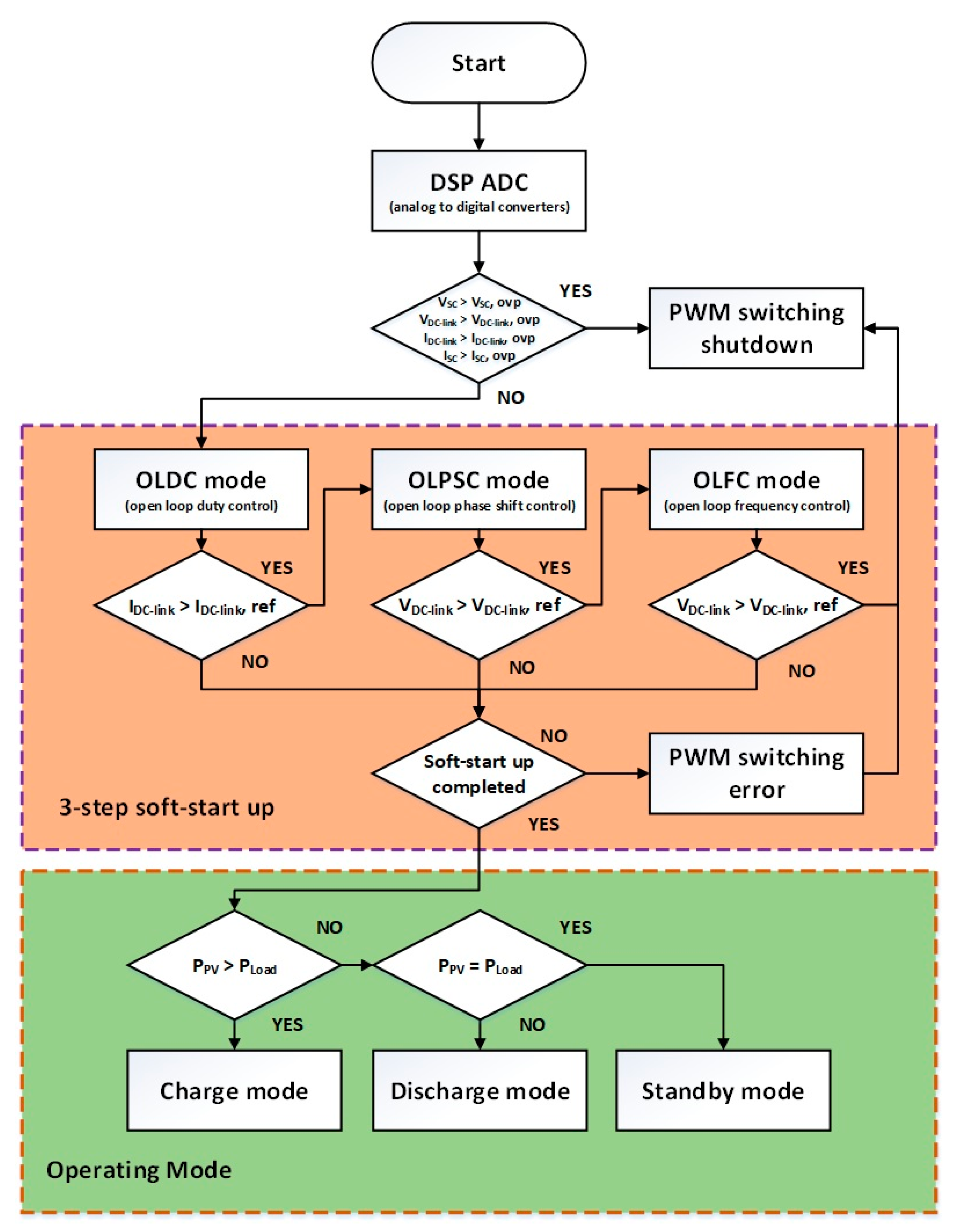
Figure 7 presents a flow chart of the proposed 3-step soft start-up algorithm for the DAB converter. The soft start-up process is started before commencing the charging or discharging operation when the system is first activated. First of all, the voltage and current value of the DC-link and SC module are sensed by the ADC (analog to digital converters) and fed to the DSP controller through isolated sensing circuits. When the overvoltage and overcurrent is checked at both sides, the DAB converter is protected by blocking the OLDC signal. If the DC-link current exceeds the reference value during the OLDC, the OLPSC that follows the reference current by phase shift is performed with the current PI controller. Nevertheless, when the reference current cannot be controlled by the OLPSC, the OLFC that follows the reference voltage by frequency is additionally performed with the voltage PI controller. Since this process takes place in a few seconds, if the voltage control of the DC-link is not possible even in OLFC mode, it is recognized as being out of the control range and the PWM signal is stopped. In addition, if the output of normal duty rate is not possible or soft start-up fails, the PWM signal is definitely limited. In this case, a reboot is manually required by an external signal. After the 3-step soft start-up operation is carried out perfectly, it is switched to charge mode, discharge mode, and standby mode according to the load power and PV power. When the PV array power is much higher than the load power, the DAB converter operates in charge mode (PPV > Pload). On the other hand, when the PV array output is lower than the load power, it operates in the discharge mode (Pload > PPV). If the PV array power and load power have the same value, it is switched to standby mode (Pload = PPV).
In the operating mode, the PI controller for CP mode is applied to perform the MPPT (maximum power point tracking) to maximize the output power of the PV array for continuous charging and discharging of the SC. When the SC is charged more than 80%, it switches from CP mode to CV mode to charge the surplus power. In addition, while operating in CV mode, the surplus power flows to the grid side to achieve the MPPT control. The charging power to the SC is sensed and compared with the reference power generated by the MPPT to perform PI control. The reference power is charged using the phase shift as the derived control value. Charging the supercapacitor should be given priority over the power generated by the solar panel rather than being consumed by the grid or load. For this reason, it operates in CP mode when charging the SC. Conversely, in discharge mode, it is required to control the DC-link voltage to 380 V because it is operated when the power of the solar panel is zero. During normal operation status, this process occurs automatically, and step-by-step action is not required in user intervention. In the discharge mode, the DC-link voltage is tracked and the output current is controlled through the DAB converter. In this case, since the PV array power is insufficient compared to the required load power, additional power is introduced from the grid side and this amount power is output from the DAB converter. On the other hand, in the standby mode, where the load power and the PV array power are the same value, no power flow occurs through phase shift control. During normal operation state, this process occurs automatically, and step-by-step action is not required in user intervention. Figure 8 shows the PI controller for CP-CV mode in charging and discharging of the SC.

4. The DAB Converter Design

Specifications of the designed DAB converter are listed in Table 1. The input voltage is set at 330 to 380 VDC to perform the grid-connected of the inverter, and the turn ratio of the transformer is designed to 3.1:1 to operate the appropriate charging voltage of the SC. In the H-bridge, a SiC MOSFET that can reduce loss and minimize circuit size is applied. The switching frequency is set to 20 kHz, which reduces the burden of high frequency switching and lowers the possibility of switching noise due to low frequencies. In addition, the inductor value was designed and applied to the transformer secondary in order to adjust the inductance value of 17 µH. When the charging voltage of the SC is 120 V, it is possible to achieve 5 kW capacity with 0.4 duty ratio. When the charging voltage is the highest at 200 V, the minimum value of phase shift has 0.17 duty ratio, enough to operate a 5 kW DAB converter. Figure 9 shows an output power graph with regards to change of SC voltage and each H-bridge phase shift.

5. Simulation Results

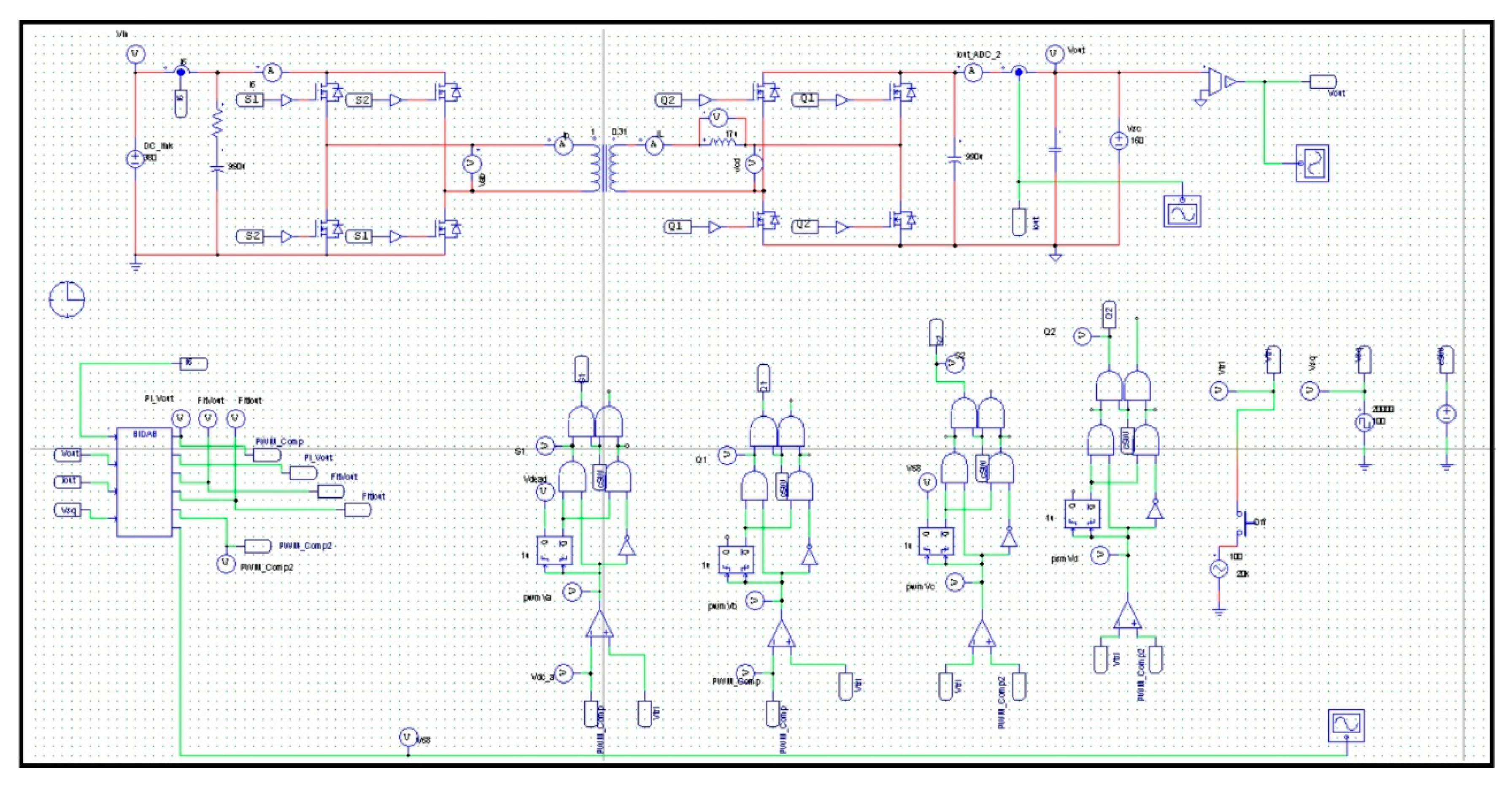
The proposed circuit was verified by simulation using PSIM. In order to verify reliable simulation results, the parameters (Table 1) of the devices and data codes were applied without discrimination. Figure 10 presents the schematic diagram of the simulation model for the DAB converter.
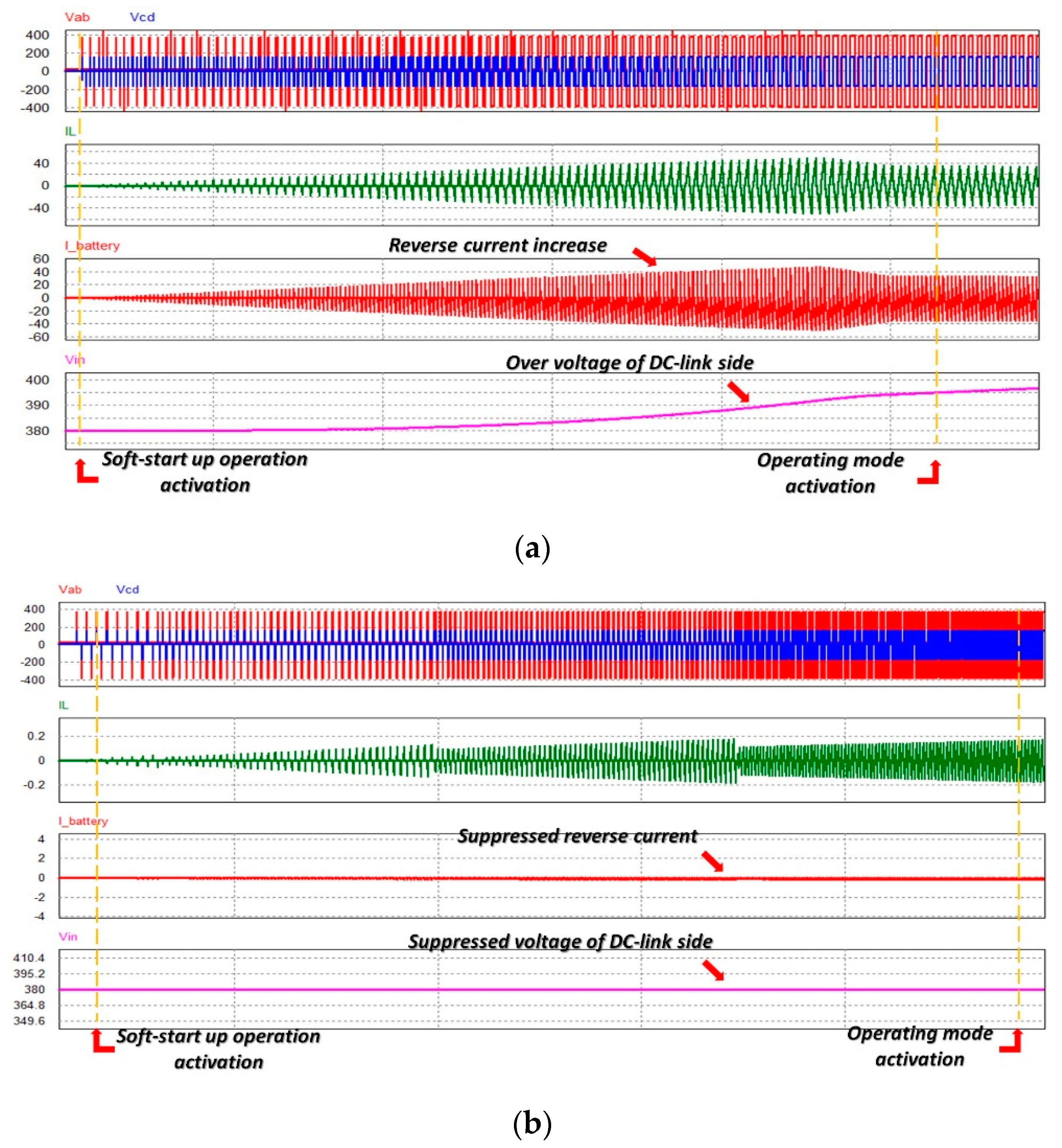
Figure 11 shows the simulation waveforms of a soft start-up operation in the DAB converter, (a) without proposed 3-step soft start-up, (b) with proposed 3-step soft start-up in the condition that the DC-link voltage is 380 V and initial SC voltage is 160 V. The first waveform in Figure 11a shows the voltage of both Vab and Vcd. The second and third waveforms show the coupling inductor current and SC current. The last waveform shows the DC-link voltage. As the soft start-up is operated step by step as the OLDC mode, due to the high voltage on the secondary side, the phase shift with a fixed switching frequency of 20 kHz occurs rapidly. Thereby, the high current flows to the DC-link side via the coupling inductor, causing a voltage increase constantly. The maximum coupling inductor current and SC current is captured at IL = 49.7 A, ISC-rms = 16.5 A. The maximum DC-link voltage is recorded at VDC_link = 408.3 V. Thus, after the soft start-up is finished, the operating mode has to be activated normally, but it leads to an abnormal error and is finally out of control.
On the other hand, these results are changed as the proposed 3-step soft start-up algorithm is applied. Initially, when the OLDC mode starts smoothly, the OLPSC mode is operated to control the large current flowing to the DC-link. As a result, the coupling inductor current is significantly lowered. However, as the duty cycle expands, the inductor current and the DC-link current increase gradually. In order to suppress the increase in voltage with reverse current flow, the OLFC is applied to control and maintain the coupling inductor current to 0.2 A or less. As the OLFC mode proceeds from the half-sequence, the variation of frequency occurs periodically, as shown in Figure 11b. The suppressed reverse current close to zero ampere appears in the third graph and the DC-link voltage controlled by 380 V appears in the fourth graph. After the proposed 3 step soft start-up ends, it is switched to standby mode for charging or discharging of the SC.

6. Experimental Setup

Figure 12 shows the designed DAB converter and experimental devices. The primary side of the DAB converter is connected to the DC power supply and power resistors instead of DC-link and grid-connected. The secondary side is connected to the SC module. The input voltage of the DAB converter was a 380 V fixed DC source, which was obtained from the DC-link with capacitors, 990 µF. The designed 5 kW DAB converter was controlled by an advanced digital microcontroller, DSP TMS320F28335.
Five SC (165 F, 53 Wh) modules for 48 V were connected in series to form a battery system with capacities of 240 V, 33 F, and 265 Wh. Figure 13 and Table 2 show the SC modules and specifications used in this experiment. Several experiments were conducted to confirm the reproducibility of the proposed system. First, a reverse power event was verified by applying a conventional soft start-up operation in a setting with high SC voltage. Second, improved operating characteristics were verified by applying the proposed controller and algorithm at the same high SC voltage. Third, the characteristics of the transient state performed after the soft start-up operation in the discharge mode were confirmed and improved. Finally, an experiment was performed to check the smooth switching of charge and discharge operations in the operating mode.

7. Results and Discussion

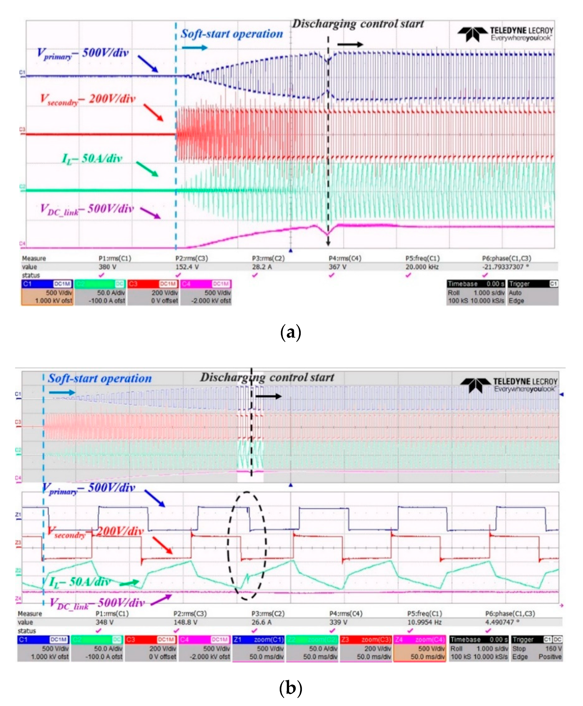
The five supercapacitor modules (265 Wh) were connected to secondary DAB converter side. First, the experiment was conducted without a 3-step soft start-up algorithm. Figure 14a shows the experimental waveforms of general soft start-up operation in the DAB converter. A typical DAB converter performs a command to generate the initial PWM signal to each bridge. This is the OLDC mode and the duty rate increases steadily. It is confirmed that the phase shift between the two H-bridges is caused by the potential difference when the soft start-up operation is enacted. Due to this condition, the DC-link voltage and coupling inductor current gradually increase from the middle stage to final stage. This means that the absence of an algorithm to control the phase difference cannot suppress the increase in DC-link voltage. When the DC-link voltage exceeds the allowable range of 500 V in the fault-check section, the PWM signal is cut off by the automatic shutdown sequence. Figure 14b shows the soft start-up zoom-in waveform before the PWM signal cut off.
Figure 15 shows the waveforms of the proposed 3-step soft start-up operation at the DAB converter. In the entire section, the coupling inductor current is suppressed by phase shift and frequency transition and the DC-link voltage is constant at 380 V. After soft start-up ends in a few seconds, it is switched to charge mode smoothly, which verifies that the CP-CV controller follows the control value. When the SC module voltage reaches the limit value of 200 V, the DC-link voltage increases in a few milliseconds; however, on rapidly controlling it, only the rising sphere is suppressed as much as possible.
The soft start-up operation of the DAB converter has to be performed even when the voltage of the DC-link is zero. This is because the voltage of the DC-link has to be maintained with the power of the SC when no voltage is output from the PV panel. In this case, after the soft start-up operation ends, the operating state is immediately switched to the discharge mode; the process is shown in Figure 16. First, when the soft start-up operation is started, the DC-link voltage is run to 380 V. If no proposed controller is applied, the DC-link voltage is temporarily reduced at the end stage. Then, the voltage is recovered as the discharge mode controller starts. In this transient state, the proposed controller and algorithm are applied to smoothly enable a mode situation, as shown in Figure 16b.
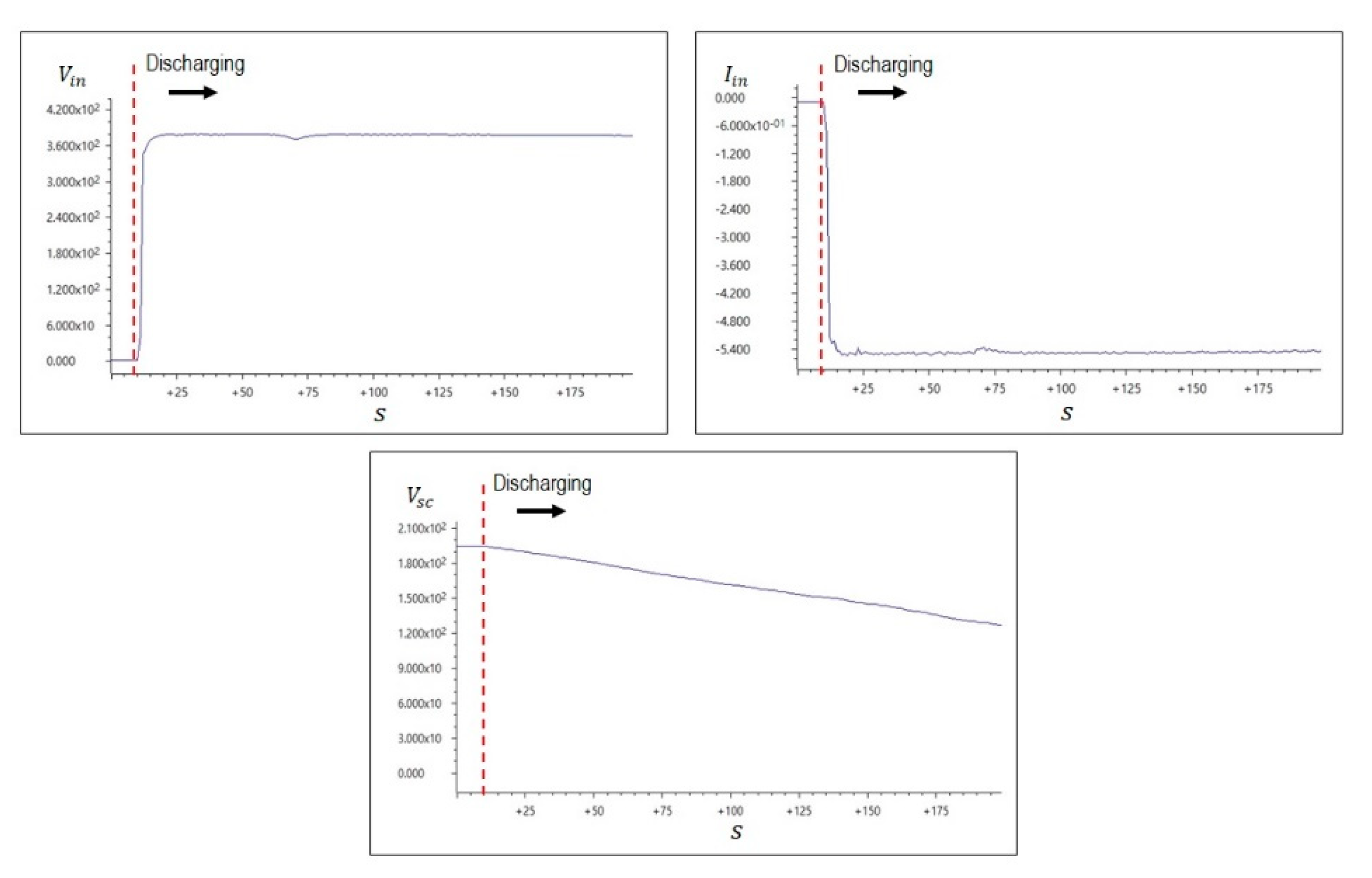
Figure 17 shows the initial charge mode waveforms after the soft start-up operation. The graph on the top left shows the voltage of the DC-link side, the graph on the right shows the current of the DC-link side, and the bottom graph shows the voltage of the SC. In the CP-CV mode, the voltage of the SC increases steadily. In addition, the voltage and current of the DC-link smoothly follows the reference value by the designed controller.
Figure 18 shows the initial discharge waveform of the SC. The graph on the top left shows the voltage of the DC-link side, the graph on the right shows the current of the DC-link side, and the bottom graph shows the voltage of the SC. In the CV mode, the voltage of the SC decreases steadily. In addition, the DC-link voltage and current smoothly follow the reference value with the designed controller.
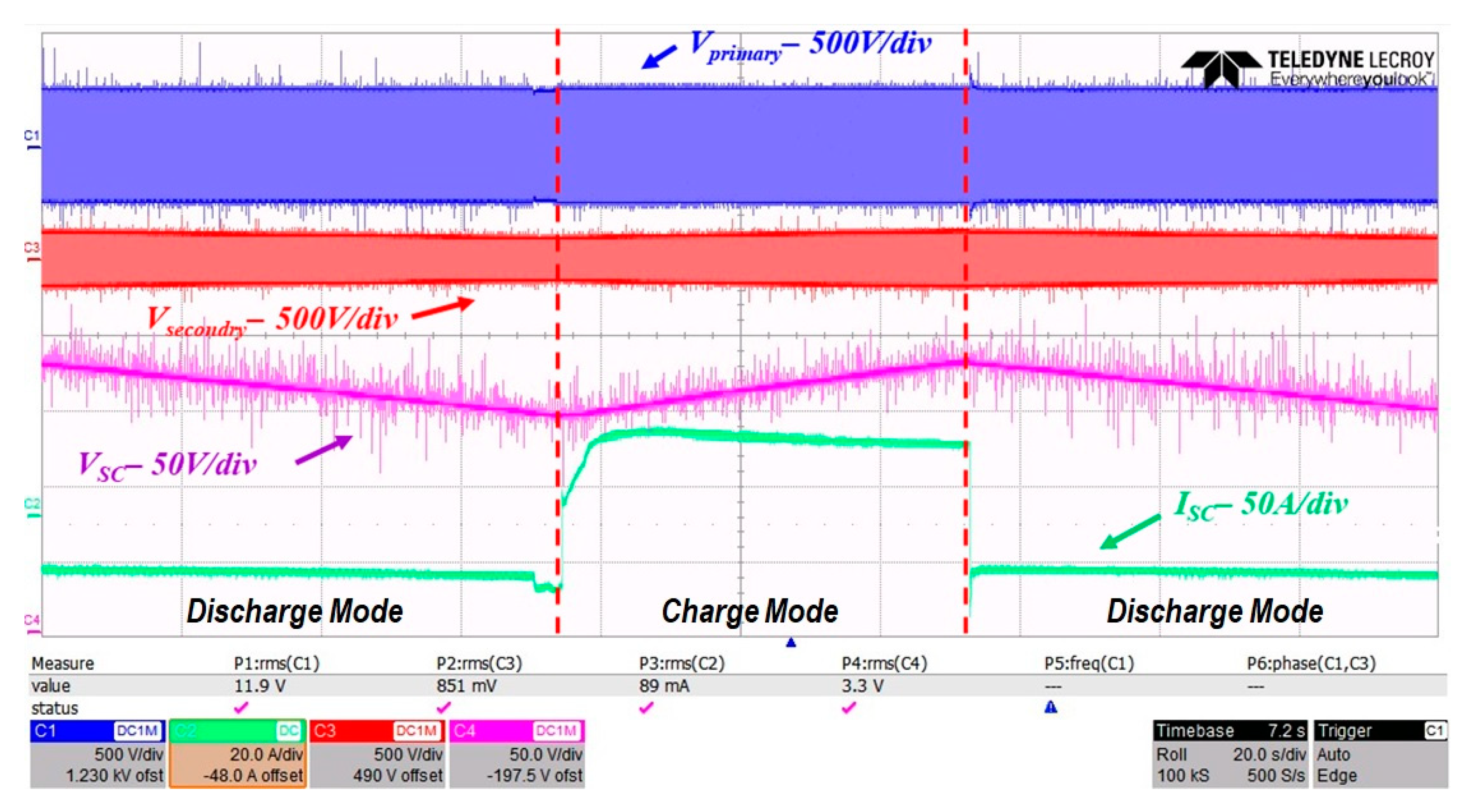
Figure 19 shows the mode switching section of the SC during charging and discharging of the SC modules. First, the discharge is started in a state where the initial voltage of the SC is high and the charging is switched when the PV power increases with regards to the reference value. According to the designed algorithm, continuous charging and discharging are activated. Stable operation at each switching mode section is confirmed.

8. Conclusions

We propose an enhanced 3-step soft start-up controller and algorithm for the DAB converter with a supercapacitor. Our proposed controller and algorithm are provided to suppress the reverse current caused by the wide voltage range of the SC. To ensure an optimal control sequence through the 3-step of OLSC, OLPSC, and OLFC, the simulations and experiments were performed with five SC (165 F, 53 Wh) modules. As a result, the DC-link voltage maintains constant value in spite of a high SC voltage. The quick switching mode is available without a transient state even after the soft start-up operation ends. In addition, the moment of mode switching from the charge mode to the discharge mode or otherwise, and the overshoot or inrush current is drastically suppressed toward the DC-link and SC module side. Our prototype 5 kW DAB converter has been designed and fabricated to demonstrate the 3-step soft start-up controller and algorithm.

Author Contributions

H.-J.K. and M.-S.K. conceptualized the idea of this research project. H.-J.K. wrote a successful proposal for the funding body. M.-S.K., D.-H.K., D.-K.J. discussed the DAB converter for PV/ESS with SC. The algorithm and controller were designed by M.-S.K., D.-H.K., and J.-M.K. The fabrication and experimental setup were mostly carried out by M.-S.K. under supervision of H.-J.K. The paper was written by M.-S.K. and H.-J.K. All authors have read and agreed to the published version of the manuscript.

Funding

This research was supported by Brain Korea 21 Center for Creative Human Resource Development Program for IT Convergence at Pusan National University.

Conflicts of Interest

The authors declare no conflict of interest.

References

  1. Pearce, J.M. Photovoltaics—A path to sustainable futures. Futures 2002, 34, 663–674. [Google Scholar] [CrossRef]
  2. Kharseh, M.; Wallbaum, H. How adding a battery to a grid-connected photovoltaic system can increase its economic performance: A comparison of different scenarios. Energies 2019, 12, 30. [Google Scholar] [CrossRef] [Green Version]
  3. Murphy, F.; McDonnell, K. A feasibility assessment of photovoltaic power systems in Ireland; a case study for the Dublin region. Sustainability 2017, 9, 302. [Google Scholar] [CrossRef] [Green Version]
  4. Atawi, I.E.; Kassem, A.M.; Zaid, S.A. Modeling, management, and control of an autonomous wind/fuel cell micro-grid system. Processes 2019, 7, 85. [Google Scholar] [CrossRef] [Green Version]
  5. Mutarraf, M.U.; Terriche, Y.; Niazi, K.A.K.; Vasquez, J.C.; Guerrero, J.M. Energy storage systems for shipboard microgrids—A Review. Energies 2018, 11, 3492. [Google Scholar] [CrossRef] [Green Version]
  6. Doerry, N.; Amy, J.; Krolick, C. History and the status of electric ship propulsion, integrated power systems, and future trends in the US Navy. Proc. IEEE 2015, 103, 2243–2251. [Google Scholar] [CrossRef]
  7. Li, X.; Hui, D.; Lai, X. Battery energy storage station (BESS)-based smoothing control of photovoltaic (PV) and wind power generation fluctuations. IEEE Trans. Sustain. Energy 2013, 4, 464–473. [Google Scholar] [CrossRef]
  8. Jeong, D.-K.; Ryu, M.-H.; Kim, H.-S.; Kim, H.-J. Optimized design of bi-directional dual active bridge converter for low-voltage battery charger. J. Power Electron. 2014, 14, 468–477. [Google Scholar] [CrossRef] [Green Version]
  9. Yun, H.-J.; Kim, H.-S.; Kim, M.; Baek, J.-W.; Kim, H.-J. A DAB converter with common-point-connected winding transformers suitable for a single-phase 5-level SST system. Energies 2018, 11, 928. [Google Scholar] [CrossRef] [Green Version]
  10. Yun, C.-G.; Cho, Y. Active hybrid solid state transformer based on multi-level converter using SiC MOSFET. Energies 2019, 12, 66. [Google Scholar] [CrossRef] [Green Version]
  11. Wang, S.; Wang, S.; Cui, Y.; Long, J.; Ren, F.; Ji, S.; Wang, S. An experimental study of the sweep frequency impedance method on the winding deformation of an onsite power transformer. Energies 2020, 13, 3511. [Google Scholar] [CrossRef]
  12. Sathishkumar, P.; Piao, S.; Khan, M.A.; Kim, D.-H.; Kim, M.-S.; Jeong, D.-K.; Lee, C.; Kim, H.-J. A blended SPS-ESPS Control DAB-IBDC converter for a standalone solar power system. Energies 2017, 10, 1431. [Google Scholar] [CrossRef]
  13. Lei, T.; Wu, C.; Liu, X. Multi-objective optimization control for the aerospace dual-active bridge power converter. Energies 2018, 11, 1168. [Google Scholar] [CrossRef] [Green Version]
  14. Xiong, F.; Wu, J.; Hao, L.; Liu, Z. Backflow power optimization control for dual active bridge DC-DC converters. Energies 2017, 10, 1403. [Google Scholar] [CrossRef] [Green Version]
  15. Jeong, D.-K.; Kim, H.-S.; Baek, J.-W.; Kim, H.-J.; Jung, J.-H. Autonomous control strategy of DC microgrid for islanding mode using power line communication. Energies 2018, 11, 924. [Google Scholar] [CrossRef] [Green Version]
  16. Aamir, M.; Mekhilef, S. An online transformerless uninterruptible power supply (ups) system with a smaller battery bank for low-power applications. IEEE Trans. Power Electr. 2017, 32, 233–247. [Google Scholar] [CrossRef]
  17. Komurcugil, H. Rotating-sliding-line-based sliding-mode control for single-phase ups inverters. IEEE Trans. Ind. Electr. 2012, 59, 3719–3726. [Google Scholar] [CrossRef]
  18. Deng, H.; Oruganti, R.; Srinivasan, D. Analysis and design of iterative learning control strategies for ups. inverters. IEEE Trans. Ind. Electr. 2007, 54, 1739–1751. [Google Scholar] [CrossRef]
  19. Rani, J.R.; Thangavel, R.; Oh, S.-I.; Lee, Y.S.; Jang, J.-H. An ultra-high-energy density supercapacitor; fabrication based on thiol-functionalized graphene oxide scrolls. Nanomaterials 2019, 9, 148. [Google Scholar] [CrossRef] [Green Version]
  20. Kanaka Durga, I.; Srinivasa Rao, S.; Ahn, J.-W.; Park, T.-Y.; Jin-Soo, B.; Ho, C.-I.; Prabakar, K.; Kim, H.-J. Dice-like nanostructure of a CuS@PbS composite for high-performance supercapacitor electrode applications. Energies 2018, 11, 1624. [Google Scholar] [CrossRef] [Green Version]
  21. Scalia, A.; Bella, F.; Lamberti, A.; Bianco, S.; Gerbaldi, C.; Tresso, E.; Pirri, C.F. A flexible and portable powerpack by solid-state supercapacitor and dye-sensitized solar cell integration. J. Power Sour. 2017, 359, 311–321. [Google Scholar] [CrossRef]
  22. Chauhan, H.; Singh, M.K.; Hashmi, S.A.; Deka, S. Synthesis of surfactant-free SnS nanorods by a solvothermal route with better electrochemical properties towards supercapacitor applications. RSC Adv. 2015, 5, 17228–17235. [Google Scholar] [CrossRef]
  23. Ali, M.U.; Zafar, A.; Nengroo, S.H.; Hussain, S.; Junaid Alvi, M.; Kim, H.-J. Towards a smarter battery management system for electric vehicle applications: A critical review of lithium-ion battery state of charge estimation. Energies 2019, 12, 446. [Google Scholar] [CrossRef] [Green Version]
  24. Liu, Y.; Jiang, K.; Yang, S. Integrated anode electrode composited Cu–Sn alloy and separator for microscale lithium ion batteries. Materials 2019, 12, 603. [Google Scholar] [CrossRef] [PubMed] [Green Version]
  25. Simon, P.; Gogotsi, Y. Materials for electrochemical capacitors. Nat. Mater. 2008, 7, 845–854. [Google Scholar] [CrossRef] [Green Version]
  26. Peng, H.; Ma, G.; Mu, J.; Sun, K.; Lei, Z. Controllable synthesis of CuS with hierarchical structures via a surfactant-free method for high-performance supercapacitors. Mater. Lett. 2014, 122, 25–28. [Google Scholar] [CrossRef]
  27. Tooming, T.; Thomberg, T.; Kurig, H.; Jänes, A.; Lust, E. High power density supercapacitors based on the carbon dioxide activated D-glucose derived carbon electrodes and 1-Ethyl-3-methylimidazolium tetrafluoroborate ionic liquid. J. Power Sour. 2015, 280, 667–677. [Google Scholar] [CrossRef]
  28. Hong, S.-J.; Hyun, S.-W.; Kang, K.-M.; Lee, J.-H.; Won, C.-Y. Improvement of transient state response through feedforward compensation method of AC/DC power conversion system (PCS) based on space vector pulse width modulation (SVPWM). Energies 2018, 11, 1468. [Google Scholar] [CrossRef] [Green Version]
  29. Khan, M.A.; Zeb, K.; Sathishkumar, P.; Ali, M.U.; Uddin, W.; Hussain, S.; Ishfaq, M.; Khan, I.; Cho, H.-G.; Kim, H.-J. A novel supercapacitor/lithium-ion hybrid energy system with a fuzzy logic-controlled fast charging and intelligent energy management system. Electronics 2018, 7, 63. [Google Scholar] [CrossRef] [Green Version]
  30. Lee, D.-M.; Hyun, S.-W.; Kang, J.-W.; Noh, Y.-S.; Won, C.-Y. A control strategy for bidirectional isolated 3-phase current-fed dual active bridge converter. Electronics 2018, 7, 214. [Google Scholar] [CrossRef] [Green Version]
  31. Litrán, S.P.; Durán, E.; Semião, J.; Barroso, R.S. Single-switch bipolar output DC-DC converter for photovoltaic application. Electronics 2020, 9, 1171. [Google Scholar] [CrossRef]
  32. Yoon, D.; Lee, S.; Cho, Y. Design considerations of series-connected devices based LLC converter. Energies 2020, 13, 264. [Google Scholar] [CrossRef] [Green Version]
  33. Fang, Z.; Wang, J.; Duan, S.; Shao, J.; Hu, G. Stability analysis and trigger control of LLC resonant converter for a wide operational range. Energies 2017, 10, 1448. [Google Scholar] [CrossRef] [Green Version]
  34. Sathishkumar, P.; Krishna, T.N.V.; Khan, M.A.; Zeb, K.; Kim, H.-J. Digital soft start implementation for minimizing start up transients in high power DAB-IBDC converter. Energies 2018, 11, 956. [Google Scholar] [CrossRef] [Green Version]
  35. Xu, W.; Chan, N.H.L.; Or, S.W.; Ho, S.L.; Chan, K.W. A new control method for a bi-directional phase-shift-controlled DC-DC converter with an extended load range. Energies 2017, 10, 1532. [Google Scholar] [CrossRef] [Green Version]
  36. Rico, J.J.; Acha, E.; Madrigal, M. The study of inrush current phenomenon using operational matrices. IEEE Trans. Power Deliv. 2001, 16, 231–237. [Google Scholar] [CrossRef]
  37. Ge, B.; de Almeida, A.T.; Zheng, Q.; Wang, X. An equivalent instantaneous inductance-based technique for discrimination between inrush current and internal faults in power transformers. IEEE Trans. Power Deliv. 2005, 20, 2473–2482. [Google Scholar]
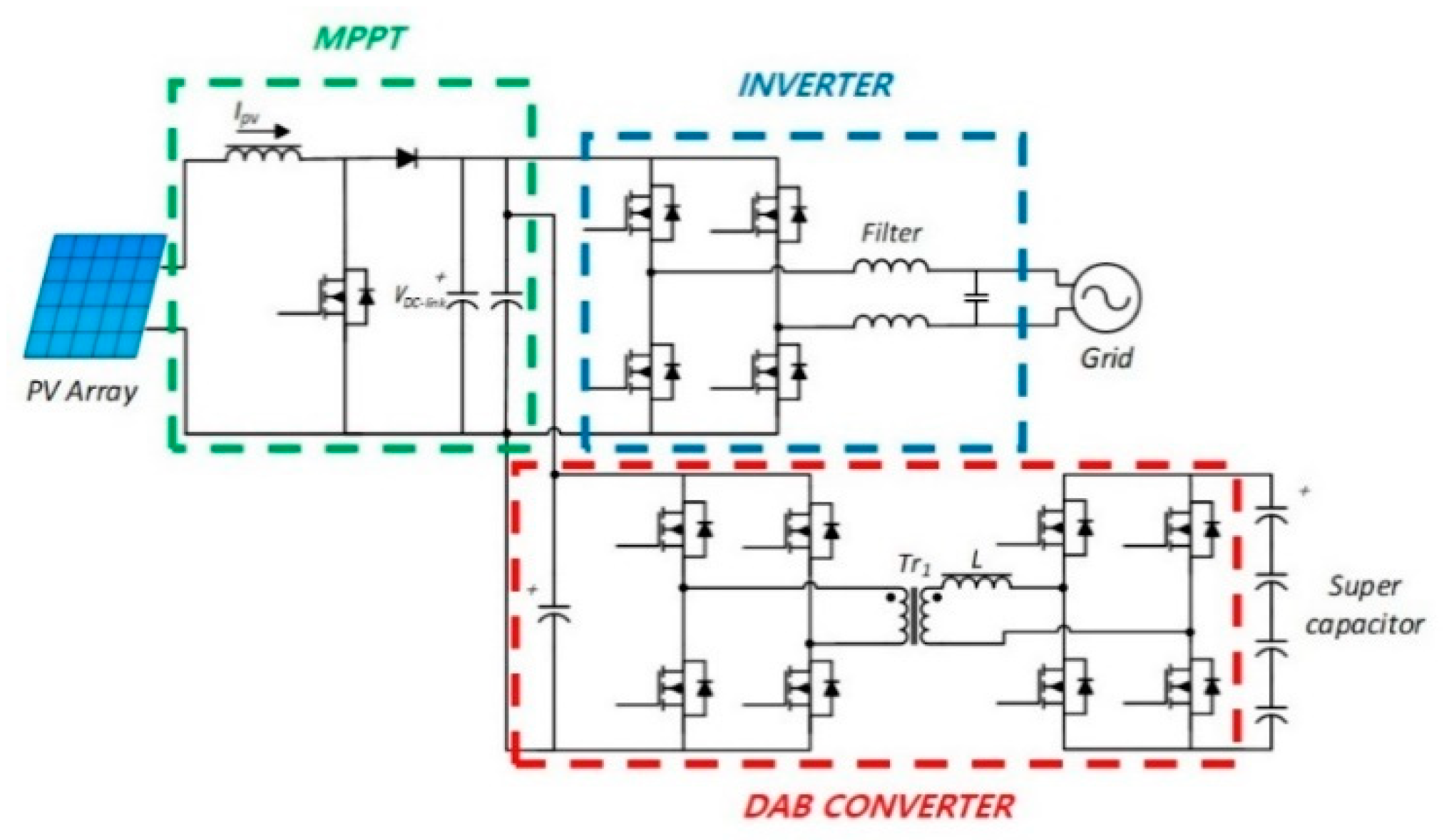
Figure 1. Configuration of PCS (power conversion system) in PV/ESS (photovoltaic/energy storage system).
Energies 13 04083 g001
Figure 2. Circuit configuration of the DAB (Dual Active Bridge) converter.
Energies 13 04083 g002
Figure 3. Current flow diagram and voltage increase of the DC-link at the soft start-up operation.
Energies 13 04083 g003
Figure 4. The DC-link voltage according to load factor and SC module voltage at soft start-up operation.
Energies 13 04083 g004
Figure 5. The process of the proposed 3-step soft start-up algorithm: (a) The open loop duty control (OLDC) in the initial stage; (b) The open loop phase shift control (OLPSC) in the middle stage; (c) The open loop frequency control (OLFC) in the final stage.
Energies 13 04083 g005
Figure 6. The voltage and current PI controller block diagram for the 3-step algorithm.
Energies 13 04083 g006
Figure 7. The proposed 3-step soft start up algorithm flow chart.
Energies 13 04083 g007
Figure 8. The PI controller for CP-CV mode in charging and discharging of the SC.
Energies 13 04083 g008
Figure 9. The relation of power between the SC voltage and phase shift.
Energies 13 04083 g009
Figure 10. Schematic diagram of the simulation model.
Energies 13 04083 g010
Figure 11. The simulation waveforms of soft start-up operation (a) without the proposed 3-step soft start-up; (b) with the proposed 3-step soft start-up.
Energies 13 04083 g011
Figure 12. The designed DAB converter and experimental devices. (a) Experimental setup captured; (b) The 5 kW DAB converter prototype.
Energies 13 04083 g012
Figure 13. The SC module (BMOD0165-P048-C01) manufactured by Maxwell Co., Ltd. (San Diego, California, USA).
Energies 13 04083 g013
Figure 14. The experimental waveforms of general soft start-up operation in the DAB converter (a) without the 3-step soft start-up controller and algorithm; (b) the initial soft start-up zoom-in before the PWM signal cut off.
Energies 13 04083 g014
Figure 15. The experimental waveforms of the proposed 3-step soft start-up operation in the DAB converter. (a) At a low voltage of SC module with the CP-CV controller; (b) at a high voltage of SC module with the CP-CV controller.
Energies 13 04083 g015
Figure 16. The experimental waveforms of soft start-up operation in discharge mode (a) without the 3-step soft start-up operation; (b) with the 3-step soft start-up operation.
Energies 13 04083 g016
Figure 17. The experimental waveforms of initial charge mode after soft start-up (VDC_link, Isc, Vsc).
Energies 13 04083 g017
Figure 18. The experimental waveforms of the initial discharge mode after soft start-up (VDC_link, Isc, Vsc).
Energies 13 04083 g018
Figure 19. Switching section between charge and discharge.
Energies 13 04083 g019
Table 1. Specifications of the designed DAB converter.
ParameterValue
Power5 kW
Input voltage380 VDC
Output voltage120 V~200 VDC
Switching frequency20~50 kHz
Leakage inductance17 µH
Transformer turn ratio3.1:1
Input capacitance990 uF
Output capacitance990 uF
Table 2. Specifications of the SC modules.
ParameterValue
Rated voltage45 V
Capacitance165 F
Maximum ESR6.0 mΩ
Stored energy53 Wh
Maximum current1900 A
Duty cyclesUp to 100,000 cycles