1. Introduction
Sustainable and environmentally benign energy sources such as wind and solar are gaining more market penetration worldwide as they become more economically competitive against high CO
2 emission fossil fuel sources, such as coal [
1,
2,
3,
4]. However, the contributions of these renewable energy sources are still limited by their intermittent and unpredictable nature [
4], which can create a challenge to the stability of the electrical network when they are integrated into the grid in large proportion. One of the methods to stabilize the electricity network and enable higher contributions from the wind and solar sources is to incorporate grid-scale storage technologies [
5,
6].
The H
2-Br
2 regenerative fuel cell is a hybrid fuel cell consisting of a gas-phase negative electrode of a fuel cell and an aqueous-phase positive electrode of a flow battery. After its first introduction in 1964 [
7], it has gained great interest from the energy storage industry and academic institutions due to the fast kinetics of its electrode reactions and low-cost energy storage electroactive materials [
8,
9,
10,
11]. An H
2-Br
2 fuel cell involves an H
2 negative electrode, a Br
2 positive electrode, and a proton exchange membrane (PEM) as the electrolyte. The initial electroactive material of an H
2-Br
2 fuel cell is the HBr solution. During the charge mode, the bromide anions are converted to the neutral bromine molecules at the positive electrode using excess electricity from an intermittent energy source like wind/solar. Simultaneously, the hydronium cations in the hydrobromide solution migrate across the PEM to the hydrogen electrode and are reduced to H
2. This process converts the electrical energy in the electricity to chemical energy in the form of hydrogen and bromine molecules while maintaining electroneutrality condition on both sides of the fuel cell. The HBr-Br
2/H
2 are stored externally in two separate storage tanks. When there is a demand for electricity from the electric grid, the electrical energy stored in the bromine and hydrogen molecules is released when the electrochemical reactions and proton transport process across the membrane described earlier are reversed, in its discharge mode, converting hydrogen and bromine back to HBr. The low price of the starting material, HBr, is one of the main advantages of the H
2-Br
2 system. Currently, the bulk price of HBr is about
$2/kg in comparison to
$15/kg for vanadium, the electroactive material used in the commercialized all-vanadium flow battery system [
12,
13].
The fast kinetics of the bromine/bromide reaction on non-precious materials, such as carbon, is another advantage of the H
2-Br
2 fuel cell. However, the hydrogen oxidation reaction (HOR) and hydrogen evolution reaction (HER) at the negative electrode requires a precious metal catalyst. The application of a hydronium-cation-selective membrane, such as Nafion
®, cannot completely prevent the crossover of the bromide anion and bromine molecules from the HBr side to the hydrogen side. Earlier durability studies of the H
2-Br
2 fuel cell show that the commonly used Pt catalyst for the hydrogen reactions is vulnerable to corrosion and poisoning by Br
−/Br
2 [
14,
15,
16]. The main challenge to the deployment of the H
2-Br
2 system has been the availability of a durable and high-activity electrocatalyst for the hydrogen reactions. The current research of HOR/HER catalyst in H
2-Br
2 fuel cells can be grouped into two main efforts, one for more durable catalysts and the other to protect the Pt catalyst. Pt-Ir-N
x/C [
17] and MoS
2-Pt [
18] have been investigated and found to be almost as active and a bit more durable than Pt in the HBr/Br
2 solution. However, their stability still does not meet the long-term (10–20 years) durability requirement for these electrochemical energy storage systems. In the efforts on protecting the Pt catalyst, the polydopamine coating on Pt was found to provide some protection of the metal from the corrosion by bromine/bromide. The impact of the polymer coating on the hydrogen reaction rate is an issue that must be addressed [
19,
20]. Our previous studies suggest that the active Rh
xS
y phases are suitable catalyst candidates for the HOR/HER in the Br
−/Br
2 solution because they show reasonable catalytic activity for the HOR/HER and outstanding stability in this corrosive environment [
21,
22,
23].
The current commercially available Rh
xS
y catalyst has two issues, low mass-specific electrochemical active surface area (ECSA) and low catalytic activity [
22]. The functionalization of the carbon support and the employment of the mass-transfer-controlled nanoparticle (NP) growth process resolve the low mass-specific ECSA caused by the large and broad distribution of NP size. Using these approaches, the Rh
xS
y catalyst nanoparticle size was reduced from ~13 nm to ~5 nm [
24,
25]. The low HOR/HER activity of the current Rh
xS
y catalyst is related to the composition of the crystal phases in the catalyst. There are three rhodium sulfide crystal phases, Rh
2S
3, Rh
3S
4, and Rh
17S
15 [
26,
27,
28]. Among these crystal structures, Rh
2S
3 is a semiconductor and has no catalytic activity while Rh
3S
4 and Rh
17S
15 show high catalytic activity for the HOR/HER. Their mixtures are often called Rh
xS
y. The non-active Rh
2S
3 phase can be converted to Rh
3S
4 and Rh
17S
15 by thermal treatment during which some sulfur atoms are removed from the Rh
2S
3 structure. In addition to the aqueous method of synthesizing Rh
2S
3 and converting it to Rh
3S
4 and Rh
17S
15 by thermal treatment used in our approach, the gas-phase process of direct sulfidation reaction of RhCl
3 and gaseous H
2S, used by others, also results in the mixture of multiple rhodium sulfide phases where the phase composition is determined by the synthesis temperature, temperature ramp rate, and treatment time [
26]. The density functional theory (DFT) calculation suggests that the Rh
3S
4 crystal phase has the highest HOR/HER activity [
27].
The substitution doping with other metal atoms has also been explored as a method to improve the intrinsic activity of rhodium sulfide. Prior doping attempts, however, show that rhodium sulfides incorporated with Ru and Pd did not show higher HOR activity [
28]. As an alternative approach to resolve the low-activity issue, we focus our efforts on the adjustment of the crystal composition of rhodium sulfide. To adjust the crystal composition of rhodium sulfide, we explored the two methods of tuning the thermal treatment temperature and exploring the new types of sulfur sources. The narrow free energy window among these three rhodium sulfide crystal phases [
29,
30] shows the challenge one faces in this conversion process. If the treatment temperature is either too low or too high, one may end up with either too much of the unconverted non-active Rh
2S
3 phase or Rh metal. Rhodium metal is an unwanted phase because it is unstable in HBr/Br
2 like platinum [
23,
31]. A recent study has shown that different sulfur sources can lead to different metal sulfide monomers (building blocks of nanoparticles) and final compositions. For example, the synthesis of nickel sulfide with sodium thiosulfate and C
2H
5NS under the same experimental conditions yield Ni
3S
4 and NiS, respectively [
32].
In this study, Na
2S was evaluated as an alternative sulfur source for synthesizing rhodium sulfide catalyst that contains a higher level of the more active Rh
3S
4 phase, instead of the ammonium thiosulfate source used in our previous studies and in the synthesis of some commercial rhodium sulfide catalysts [
22,
23,
24,
25,
33,
34,
35]. To the authors’ best knowledge, this is the first reported work to use different sulfur sources to adjust the crystal phases of Rh
xS
y. Cyclic voltammetry (CV) was used to determine the increase in the mass-specific surface area of the rhodium sulfide catalysts synthesized with the functionalized carbon substrate and the diffusion-controlled nanoparticle growth process, and to prove that the rhodium sulfide catalyst synthesized by Na
2S had a higher HOR activity. The higher HOR activity of the catalyst will also be validated by the linear polarization curves obtained by the multiple-step chronoamperometry. Transmission electron microscopy (TEM) was used to confirm the decrease in the average particle size of nanoparticles. X-ray Photoelectron Spectroscopy (XPS) was the main method used to confirm the surface elemental composition of the crystal phase that was responsible for the increase in the activity of the Rh
xS
y catalyst synthesized with Na
2S. The H
2-Br
2 fuel cell tests were the final validations used to compare the performance of the rhodium sulfide catalyst on functionalized carbon support synthesized with Na
2S to those of the rhodium sulfide catalyst synthesized with ammonium thiosulfate and the commercial rhodium sulfide.
3. Results
The Rh atoms in the crystal structures of Rh
xS
y can roughly be divided into two categories, Rh atoms bonded with neighboring Rh or neighboring S. The rhodium atoms coordinated with another Rh atom in the crystal structure have more metal characteristics and are the more catalytic active centers for the HOR. These active HOR sites are also active sites for the HER. The rhodium sites coordinated with sulfur atoms and the sulfur atoms are both active sites for the HER. The dual catalytic centers make the Rh
xS
y a bifunctional catalyst for the HER and HOR where the HER activity is higher than the HOR active because of the larger number of HER sites versus HOR sites. DFT studies show that the Rh
3S
4 phase should exhibit the highest HOR activity [
27]. The different Rh-Rh bond energies in the crystal structures may explain the reason. The closest Rh-Rh bond lengths of metal Rh, Rh
2S
3, Rh
3S
4, and Rh
17S
15 measured by experiments are 2.73 Å [
29], 3.20 Å [
39], 2.70 Å [
40], and 2.63 Å [
29], respectively, among which the bond length of Rh
3S
4 is closest to that of metal Rh. The similarity between the bond lengths of Rh
3S
4 and Rh suggests that the HOR-active Rh centers of Rh
3S
4 have the most similar electronic density with those of metal Rh. The Pm3m space group of Rh
17S
15 contributes to a stronger Rh-Rh bond with a shorter length. The adsorption and desorption of reactant and product require an appropriate electron density of active sites based on the Hammer-Norskov model [
41]. In this case, the higher electron density of the Rh centers in Rh
17S
15 may result in an over-strong adsorbate H-metal (Rh of Rh
17S
15) bond which could finally obstruct the removal of the product H
+ in the HOR. As described in
Section 1, inappropriate treatment temperatures could lead to the formation of metal Rh or excessive inactive Rh
2S
3 phase, due to the narrow free energy window among Rh
2S
3, Rh
3S
4, and Rh
17S
15. Applying a new type of sulfide anion source was tried in this study to increase the composition of Rh
3S
4 in the Rh
xS
y catalyst mixture.
In the rhodium sulfide synthesis reported in the previous publications [
22,
23,
24,
25] and in the patent by De Nora [
39], the source of rhodium was the RhCl
3 solution, and the source of sulfur was provided by the dissociation of (NH
4)
2S
2O
3 [
25]. In this study, a new type of sulfur source, Na
2S, was used to provide the sulfide ions in the synthesis of Rh
xS
y. In the first part of the study, the new sulfur source was used to synthesize rhodium sulfide catalysts on the untreated commercial carbon substrate XC72R. Besides the different sulfur sources, the same thermal treatment temperature and ramp rates as those of the catalyst with (NH
4)
2S
2O
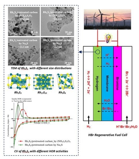
3 were used. An interesting fact that the Rh
xS
y catalyst with Na
2S as the sulfur source (purple curve with downward triangle markers) is more active than the catalyst synthesized with (NH
4)
2S
2O
3 can be found in the cyclic voltammogram in
Figure 1. The Rh
xS
y/untreated carbon synthesized by Na
2S shows a lower overpotential for the HOR as compared to those of the Rh
xS
y/untreated carbon with (NH
4)
2S
2O
3 (blue curve with circle markers), indicating that the usage of Na
2S is a potential approach to increase the HOR activity of rhodium sulfide catalyst.
The cation and anion in the synthesis solution changed when Na2S was used instead of (NH4)2S2O3. To identify the sources of the improvement in activity of the catalyst, sulfide compounds with a different combination of cations and anions, K+, Na+, S2−, and S2O32− were used to synthesize RhxSy. The influence of the type of cations to the final activity can be excluded or confirmed by introducing different cations while maintaining the same anions in the sulfide compounds. No change in the size and location of the HOR peak of the CVs was observed when the sodium ion in Na2S (purple curve with downward triangle markers) was replaced by the potassium ion in K2S (red curve with square markers). The same result was observed with the catalysts synthesized with (NH4)2S2O3 (blue curve with circle symbols) and Na2S2O3 (green curve with upward triangle symbols). The RhxSy catalysts synthesized with Na2S and K2S show similar HOR peak voltages that are more negative than those of the RhxSy catalysts made with the thiosulfate sulfur sources. The results from these two groups indicate that the cation in the sulfur source has no effect on the rhodium sulfide catalytic performance. Rather, the HOR activity of RhxSy catalysts is affected mainly by the anion source. Moreover, the more active catalysts come from the sulfur sources with the sulfide S2− anions. The reason as to why the direct sulfide S2− anion source led to higher HOR activity versus the indirect thiosulfate S2O32− source will be discussed later in Figure 5.
After we confirmed that the increase in the HOR activity of the Rh
xS
y catalysts was associated with the readily available sulfide anion in the solution (when Na
2S or K
2S was used), the new sulfur source was combined with the carbon functionalization process and the diffusion-controlled nanoparticle growth process developed in our previous study to synthesize the high-active-surface-area and high-HOR-activity Rh
xS
y catalyst. From the results given in
Figure 2a, the mass-specific ECSAs obtained from the HOR peak of the cyclic voltammograms of the Rh
xS
y catalyst on pretreated carbon synthesized with Na
2S (green curve with upward triangles) and (NH
4)
2S
2O
3 (blue curve with circles) increased more than four folds over those with untreated carbon substrates. These results show the effectiveness of the carbon functionalization and diffusion-controlled particle growth process in reducing the catalyst nanoparticle size. The slightly higher increase in the ECSA of the catalyst synthesized with Na
2S (4.6 versus 4.0 times) can be attributed to the smaller nanoparticles (NPs) that were obtained when a slower rate was used to add the Na
2S solution to the synthesis solution. As reported in the previous work [
24], the (NH
4)
2S
2O
3 was added in 15 equal aliquots with a 2-min interval (30 min total) while in this process the Na
2S amount was added to the synthesis solution over a duration of 2 h by a peristaltic pump. Our previous work has shown that maintaining a low concentration of Rh
2S
3 monomer in the bulk solution could lead to the diffusion-controlled nanoparticle growth condition that resulted in the more dispersed and smaller nanoparticles. Next, the results in
Figure 2a also show that the HOR onset potentials and mass-specific current density peaks of the catalysts synthesized with Na
2S are shifted to a more negative potential. These characteristics suggest that these catalysts had a higher HOR specific activity, which, if it were true, would be confirmed by the polarization curves of these catalysts.
The linear polarization results in
Figure 2b show that the active-area-specific HOR/HER activities of the rhodium sulfide catalysts synthesized with Na
2S on the untreated/pretreated carbons are higher (i.e., lower vs. I slopes) than those of the catalysts synthesized with (NH
4)
2S
2O
3, validating the CV results presented in
Figure 2a. Since the current density used in
Figure 2b is the current per ECSA of the catalyst, the exchange current density i
o here is the ECSA-based exchange current density. By multiplying the mass-specific ECSA obtained in
Figure 1, the mass-specific exchange current density i
o* can be calculated. The HOR/HER active-area-specific activities of the Rh
xS
y catalysts made with Na
2S are 1.2 times (0.56 A/cm
2 vs. 0.47 A/cm
2) and 1.3 times (0.81 A/cm
2 vs. 0.62 A/cm
2) those of the Rh
xS
y catalysts made with (NH
4)
2S
2O
3 on untreated and pretreated carbon substrates, respectively. It is also worth noting that the higher activity of the Rh
xS
y catalysts obtained with Na
2S is not affected by the slow addition rate of the sulfur source solution and the types of the carbon substrate. The decrease in the NPs size by the application of functionalized carbon and the mass-transportation-controlled nanoparticle growth process using the slow sulfur source addition rate approach is confirmed by the TEM micrographs in
Figure 3. With this combined approach, the average particle size of the Rh
xS
y/pretreated carbon synthesized with (NH
4)
2S
2O
3 decreases to 5.2 nm, while that of the Rh
xS
y/pretreated carbon synthesized with Na
2S decreases further to 3.2 nm with a lower sulfur source addition rate.
As in the previous discussion, the voltages of the HOR peaks of the Rh
xS
y synthesized with Na
2S and (NH
4)
2S
2O
3 in
Figure 1 are the main observed differences. Moreover, the results in
Figure 1 hinted that the change in the Rh
xS
y activity could be attributed to the type of the anion source. The smaller overpotential of the HOR in
Figure 1 and the higher catalytic activity from the linear polarization results in
Figure 2b confirm that the Rh
xS
y synthesized with Na
2S has a higher HOR activity. XRD and XPS were used next to explore the nature of the different activities of the Rh
xS
y synthesized with Na
2S and (NH
4)
2S
2O
3.
In
Figure 4a,b, the XRD results show that the crystal structures of the Rh
xS
y are not modified by the use of the functionalized carbon substrate since the XRD patterns of the Rh
xS
y on the untreated carbon (blue and purple curves), and the pretreated carbon (red and green curves) are similar. The Rh
xS
y synthesized with Na
2S and (NH
4)
2S
2O
3 on both of the untreated and treated carbons show distinctively different characteristic XRD peaks at 36–43° and 72–75°, respectively. In the first fingerprint characteristic region (36–43°), the Rh
xS
y made from the conventional sulfur source, (NH
4)
2S
2O
3, has the intensity peak strength sequence as P4 > P1 > P3 > P2, while the catalyst made with Na
2S shows the intensity peak order of P1 > P4 > P3 > P2. The possible reasons for the change in the intensity order of the XRD fingerprint region may be attributed to the different crystal facets or the different crystal phases of the catalysts. The standard crystal patterns of Rh
17S
15 and Rh
3S
4 from ICDS also show that Rh
17S
15 has a peak located at around 73°, while Rh
3S
4 shows nothing. The second fingerprint region in
Figure 4b shows that the catalysts synthesized with (NH
4)
2S
2O
3 have a stronger peak, while the catalysts synthesized with Na
2S show a weaker peak. The stronger characteristic peak at 73° may be attributed to a higher content of Rh
17S
15 in the Rh
xS
y made with (NH
4)
2S
2O
3, and the weaker peak at 73° of the Rh
xS
y made with Na
2S may likewise be attributed to a lower Rh
17S
15 and higher Rh
3S
4 composition. The changes in the XRD spectra in
Figure 4b suggest that there is a different crystal composition between the Rh
xS
y catalysts synthesized with (NH
4)
2S
2O
3 and Na
2S. However, XRD cannot detect Rh
3S
4 well because of its low crystallinity, which means that XRD is not a highly convincing characterization method to address this question [
26,
40].
The bonding information of Rh atoms in Rh
17S
15 and Rh
3S
4 measured by XPS may be a better indicator of the HOR/HER activity improvement. It is clear in
Figure 4c that the binding energy of Rh atoms of the Rh
xS
y synthesized with Na
2S has a higher energy (~0.25 eV) than those of the Rh
xS
y from (NH
4)
2S
2O
3, indicating that these two types of Rh
xS
y catalysts may have different outer electronic structures of Rh. The electronegativity of Rh (2.28) and S (2.58) may cause a shift in the peak positions. The electrons of the bond tend to concentrate at the atom with the larger electronegativity. A more positive XPS peak indicates the Rh atoms have a lower electron density that is caused by more coordination with the neighboring sulfur atoms [
42]. The space group C2/m tells that half of the rhodium atoms in the Rh
3S
4 phase are fully coordinated by the six surrounding S atoms, while three-quarters of the rhodium atoms in the Rh
17S
15 phase with the space group Pm3m are only coordinated with the four neighboring S atoms [
29,
43]. The crystal structures of the multiple crystal phases of rhodium sulfide can be found in
Figure 5. Based on the crystal structures, it is inferred that the Rh
xS
y synthesized with Na
2S contains more Rh
3S
4, due to the positively shifted Rh 3d peak position (the lower electron density on Rh centers). According to the DFT calculation, the Rh
3S
4 phase is a more active catalyst for the HOR/HER [
27]. Therefore, a higher percentage of the more active crystal phase Rh
3S
4 can contribute to the higher activity of the rhodium sulfide catalysts synthesized with the Na
2S.
The different compositions of the crystal phases in the two rhodium sulfide catalysts may be explained by the mechanisms that generate the sulfide anion from S
2O
32− and S
2−. Na
2S is a strong electrolyte that dissociates into Na
+ and S
2− completely and immediately, although with some hydrolysis of S
2−. The concentration of Na
2S used in this synthesis is 4.5 M, while the pH of the Na
2S solution was measured as 10.8. From the hydrolysis formula of S
2− (S
2− + H
2O
− > HS
− + OH
−), one can infer that only 0.014% S
2− was hydrolyzed in this process. The dominant form of sulfur in the Na
2S solution is S
2−. On the other hand, (NH
4)
2S
2O
3 releases the S
2− via a two-step mechanism as shown below,
Compared to the direct dissociation of Na
2S, the two-step dissociation of (NH
4)
2S
2O
3 releases sulfide anion slowly. Since the dissociation of S
2O
32− releases H
+, the level of S
2O
32− dissociation can be determined by measuring the pH of the solution. Two H
+ cations are released per dissociated S
2O
32− in the equation above.
Figure 6 shows the dissociation level of (NH
4)
2S
2O
3 versus the temperature. The results show only 0.0025% of S
2O
32− dissociated when the solution was heated from room temperature to the reaction temperature of the Rh
2S
3 precursor synthesis process (100 °C). It can be inferred from these results that the dissociation of thiosulfate in the synthesis of Rh
2S
3 is driven by the consumption of sulfide ions by the precipitation with Rh
3+. The equilibrium of the dissociation reaction of thiosulfate is continuously driven forward by the Rh
3+ sulfidation reaction. In our synthesis process, 20% excess sulfur source was used to precipitate all of the expensive precious rhodium. At the end of the precursor synthesis process, the extra S
2O
32− exists mostly in the form of S
2O
32− instead of S
2−. On the other hand, the Na
2S dissociates completely and quickly. Consequently, the extra Na
2S stays in the S
2− form after the complete sulfidation of Rh
3+. The extra S
2− may be either left on the precursor surface or incorporated into the amorphous Rh
2S
3 particles, due to its small size and affinity with the coordinated sulfur atoms in the precursor. Since Rh
xS
y is a type of heterogeneous catalyst which only catalyzes the reactions on the surface, the crystal phase composition on the catalyst surface determines the catalytic activity. Although most of the extra S
2− may be removed during the catalyst preparation, the residue of the extra S
2− in the particles should still be enough to modify the catalyst phases on the surface.
After the Rh
2S
3 precursor was synthesized, it was converted to the active Rh
3S
4 and Rh
17S
15 phases by the thermal treatment at 700 °C. The ΔG of the conversion of Rh
17S
15 to Rh
3S
4 is around –85 kJ/mol at 700 °C indicating that this conversion is spontaneous and can occur if extra sulfide ions are available [
45]. We hypothesized that the extra S
2− in the particles provided by the excess Na
2S facilitated the formation of the more active crystal phase Rh
3S
4 during the thermal treatment process based on the phase diagram and the dissociation mechanisms. The results shown in
Figure 7 support this hypothesis. The HOR peaks of the Rh
xS
y catalysts with 120% (NH
4)
2S
2O
3 and Na
2S are located at 71 mV and 43 mV, respectively. When the excess amount of Na
2S was reduced from 120% to 103%, the HOR peak voltage shifted from 43 mV to 55 mV, indicating a lower HOR activity. The lack of extra S
2− in the thermal treatment decreases the generation of the more active Rh
3S
4 phase and finally results in lower activity.
Once the cause for the improved activity with Na
2S was identified, the performance of the Rh
xS
y catalyst synthesized with extra Na
2S and the functionalized carbon material was tested in an H
2-Br
2 fuel cell. To achieve a better fuel cell performance, the Nafion
® ionomer-unfriendly ketone groups on the carbon surface that were needed for the high dispersion and precipitation of the rhodium sulfide nanoparticles in the catalyst synthesis process have to be converted into the Nafion
® ionomer-friendly carboxylic groups. As reported in the previous publications [
24,
25], the performance of the Rh
xS
y catalyst on the ketone-dominated carbon surface substrate decreases rapidly in the high current density region because of the high mass transport resistance created by the poor affinity of the ketone groups to the Nafion
® ionomer in the catalyst ink. This poor affinity of the catalyst for the Nafion
® ionomer results in a non-uniform, poorly dispersed, and thick ionomer electrolyte coating that reduces the effective electrochemical active area in the catalyst layer and highly hinders the transport of hydrogen molecules to the catalyst surface. Our previous work confirms that the Nafion
®-unfriendly ketone groups on the carbon surface can be converted to the Nafion
®-friendly carboxylic groups by using the Baeyer–Villiger reaction and ester hydrolysis process without any adverse effect on the precipitated catalysts [
24].
Figure 8 shows the polarization curves of the hydrogen-bromine fuel cells with Rh
xS
y catalysts on the pretreated/untreated carbons synthesized by Na
2S and (NH
4)
2S
2O
3 and the commercial catalyst. These curves have been IR-corrected to remove the ohmic contribution from the membrane, electrolyte, and electronic components in the fuel cell. This IR correction allows only the effect of the kinetic and mass transport effects in the cell to be investigated. Note that all the pretreated carbons used here had been subjected to the surface functional conversion from the ketone group to the carboxylic group by the Baeyer–Villiger and hydrolysis reaction process. The performance of the fuel cells with the Rh
xS
y/
untreated carbon synthesized by Na
2S and (NH
4)
2S
2O
3 is limited by their low mass-specific electrochemical active surface area, 9.3 and 9.1 m
2/gm-Rh, respectively. With the functionalized carbon, mass-transfer-controlled nanoparticle growth process, and the surface functional conversion, the fuel cells with the Rh
xS
y on the carboxylic-dominated treated carbon synthesized with Na
2S and (NH
4)
2S
2O
3 show lower kinetic resistance, no mass transfer resistance created by the ketone-Nafion
® ionomer repulsion [
25], and much better charge and discharge performance. The Rh
xS
y catalyst with higher activity from the higher Rh
3S
4 composition and larger ECSA from the smaller nanoparticle size obtained from the optimized addition rate of the new Na
2S sulfur source outperforms all other catalysts in the fuel cell test. Its discharge performance at 200 mV below the OCV (i.e., overpotential) of the fuel cell is 1.2 times and 6.2 times higher than that of the catalyst synthesized by (NH
4)
2S
2O
3 on treated carbon and untreated carbon and 2.5 times better than that of the commercial catalyst from BASF. The fact that the mass-specific HOR activity of the Rh
xSy/pretreated carbon with Na
2S as the sulfur source was improved by 48% over that of the Rh
xS
y/pretreated carbon with (NH
4)
2S
2O
3 as the sulfur source while its fuel cell performance was only increased by 16% shows that the improvement achieved in the RDE test was not fully demonstrated in the fuel cell system test. The reason may be attributed to the fact that the Nafion
®:catalyst ratio currently used in the catalyst ink was not yet optimized for this new catalyst. We suspect that a higher Nafion
®:catalyst ratio may be needed to coat the higher mass-specific surface area achieved in this new catalyst. This aspect will be investigated in our future research.
Finally, as explained in our previous papers, the fuel cell charge performance with rhodium sulfide catalysts, which are bifunctional catalysts, is always better than the discharge performance because the hydrogen evolution reaction occurs on both the rhodium and sulfur surface sites, while the hydrogen oxidation reaction occurs only on the rhodium surface sites. While the optimization and improvement of the discharge performance of hydrogen-bromine fuel cell have been our primary focus, any improvement that is achieved with the HOR performance during the discharge mode is expected to affect also the HER performance during the charge mode of the fuel cell.


