Article

Analysis and Evaluation of Multi-Energy Cascade Utilization System for Ultra-Supercritical Units

1
School of Energy and Power Engineering, Shandong University, Jinan 250061, China
2
Shandong Electric Power Engineering Consulting Institute Corp., LTD, Jinan 250061, China
3
School of Thermal Engineering, Shandong Jianzhu University, Jinan 250101, China;
*
Authors to whom correspondence should be addressed.
Energies 2020, 13(15), 3969; https://doi.org/10.3390/en13153969
Submission received: 26 June 2020 / Revised: 27 July 2020 / Accepted: 28 July 2020 / Published: 2 August 2020

Abstract

:
To address the large temperature difference in the air heater (AH) inlet of a traditional exhaust heat utilization system and energy grade mismatch problems during the heat and mass transfer processes, this study proposed a new multi-level waste heat cascade utilization system. Based on a principle of “temperature-to-port and cascade utilization”, this system uses the boiler side high-temperature flue gas and low-temperature air, and the turbine side high-temperature feed water and low-temperature condensate water, to conduct cross heat exchange according to the energy grade matching principle. Combined with a typical 1000 MW coal-fired unit, the heat transfer characteristics and energy-saving benefits of the new system were analyzed. The results showed that the new system has excellent performance: the heat rate decreased by 91 kJ/kWh, coal consumption decreased by 3.3 g/kWh, and power generation efficiency increased to 49.39%.

1. Introduction

In line with its economic development increasing energy consumption demands, China faces enormous environmental and energy pressures. In 2017, China’s total energy consumption was 4.49 billion tons of standard coal, and coal consumption accounted for approximately 61.4% of total energy use [1]. Developing a clean production coal-power unit, saving further energy, and reducing emissions of coal-power units are the most feasible approaches to easing China’s energy pressures.
The exhaust heat loss is the largest loss of a boiler’s heat losses. It generally amounts to approximately 4% to 12%, and accounts for 60% to 70% of the boiler heat loss [2]. The main factor affecting the heat loss of the exhaust gas is the temperature. Research has shown that with each reduction of the exhaust temperature by 22 °C, the boiler efficiency is increased by approximately 1% [3]. In actual operation, many coal-fired power plant boiler exhaust gas temperatures are greater than the designed values. Therefore, reducing the exhaust gas temperature and making full use of the exhaust gas waste heat have important practical significance for saving fuel and reducing pollution.
At present, the approaches to optimizing the utilization of flue gas waste heat at the tail of a boiler are as follows: low-temperature flue gas heat exchanger technology [4,5,6], which mainly focuses on the research and application of heat-receiving surface elements; polytetrafluoro ethylene, polyvinyl chloride, and other coating materials, for effectively improving the heat exchanger resistance to smoke dew point acid corrosion; and air heater (AH) grading series optimization [7], In addition, Li combined a raw coal pre-drying system and tail flue gas system [8], and Han arranged a preposition economizer in a bypass flue and proposed a depth waste heat utilization system combining low–low temperature electrostatic precipitator(ESP) [9,10]. The 712 MW coal-fired unit of the Mehrum power plant in Germany is equipped with a low-temperature economizer (LE) at the tail. The LE reduces the flue gas temperature and heats the duct inlet air temperature using circulating water as a medium, ultimately improving the flue gas waste heat utilization quality [11]. The 950 MW Nideraussem power plant in Germany is equipped with a high temperature economizer installed in the bypass flue system of the air preheater to heat the condensate water of the high- and low-pressure extraction steam regenerative system of the steam turbine [12].
The current research focuses on heat exchanger optimization and engineering case analysis [13,14,15,16]. However, research on the potential energy saving inside boilers and steam turbines remains limited. Through the reasonable design of waste heat utilization systems, the cross utilization of steam turbine and boiler energy can be realized. In order to further reduce coal consumption and improve the energy saving efficiency of a double reheat unit, this study proposes a new type of boiler-turbine deep-coupled multi-level cascade utilization system for an ultra-supercritical power plant. In this system, a front air preheater is added that makes use of the cross heat transfer of the condensate and bypass flue gas to increase the first low-temperature economizer (I LE) inlet temperature and strengthen heat transfer on the turbine and boiler side. The system realizes a four-stage cascade utilization of waste heat. This study further analyzes the thermal performance and economy of one 1000 MW double reheat unit in China and compares it with a conventional waste heat saving system.

2. Thermodynamic Analysis and Evaluation Method

2.1. Basic Assumptions

This study conducted a theoretical analysis of an ultra-supercritical boiler-turbine coupling multi-level cascade utilization system, and evaluated the new system based on an equivalent enthalpy drop method and a whole plant evaluation index (such as the net efficiency and/or power supply standard coal consumption). The system makes the following basic assumptions: (1) the steam flow of the unit is constant, (2) the fuel supply of the unit is constant, (3) the efficiency of the boiler and the efficiency of the cylinder are not changed, (4) the pressure loss of the AH and each heat exchanger are not counted, and (5) the primary and secondary air rates remain unchanged. Table 1 shows the symbols and nomenclature in this paper.

2.2. Brief Introduction of Thermodynamic Calculation Method

The power generation efficiency and turbine heat rate are commonly used in the electric power industry to evaluate the thermal performances of power generation units [17]. Based on a common coal-fired power plant, the unit efficiency is defined as follows:
η = P e Q CP
In the above, QCP refers to the total energy input to the unit, and specifically here is considered as the chemical energy of the coal, which is equivalent to the low heat value (LHV). Pe refers to the effective energy generated from the steam turbine. The measurement units for Pe and QCP are the same (kW, MW). The heat rate is defined as follows:
q = Q CP P e = 3600 / η
The standard coal consumption of the unit is as follows:
b CP = 0.123 η
η is the comprehensive efficiency of the power generation. It refers to ηgd (the efficiency of the pipe), ηqn (the efficiency of the turbine), and ηgl (the efficiency of the boiler). The low calorific value of standard coal is equal to 29,271 kg/kJ, and the unit for bCP is kg/kWh.
The boiler island efficiency can be expressed as follows:
η b = Q b Q cp = [ D b ( h b h w ) + D RH 1 ( h RH 1 out h RH 1 in ) + D RH 2 ( h RH 2 out h RH 2 in ) ] / Q cp
The boiler island efficiency after the waste heat utilization system action is as follows:
η b 0 = η b + ( ( h CAH in h CAH out ) ( h FG 2 h FG 1 ) ) / Q cp
Here, Qb refers to the boiler heat load, a reheating unit equal to the enthalpy difference, and the boiler efficiency after the waste heat utilization system action is related to the air enthalpy in the air pre-heater. hCAH refers to the air enthalpy before and after the CAH, and hFG refers to the comprehensive flue gas enthalpy in the AH bypass and main air pre-heater.
The heat of the flue gas heating condensate can be regarded as a pure heat input turbine island, and the heat for the conversion process can be calculated according to an equivalent enthalpy drop method. After starting the new waste heat utilization system, the new steam flow increase in work is equal to the new steam enthalpy drop, as follows:
H = 3600 / η qn d 0
In the above, ηqn refers to the efficiency of the steam turbine, and d 0 refers to the steam rate of the power unit. The main flue gas, I and II LEs (described more fully below), bypass flue-first stage high-temperature heater, and bypass second-stage low-temperature heater heat the high-temperature feed water and low-temperature condenser, and discharge the corresponding extraction steam back to the heat system to work. This process leads to the amount of work change, as follows:
Δ H j = Q b η j / D b
Here, ηj refers to the efficiency of the j stage steam, D b refers to the main steam flow in the waste heat system, and Qb refers to the added flue gas heat.
The thermal economy of the new system is as follows:
δ η i = Δ H H + Δ H

3. New Boiler-Turbine Coupling Multi-Level Cascade Utilization System

3.1. Unit Introduction

In this study, a 1000 MW ultra-supercritical unit was selected as the research object, and case studies and calculations were conducted. The parameter settings that maximize the continuous power are 35 MPa/615 °C for the main steam, and 630 °C for re-heat steam. The unit adopts an ultra-supercritical secondary intermediate reheat condensing steam turbine and boiler. The coal is designed for boiler combustion (the carbon, hydrogen, oxygen, nitrogen, sulfur, and moisture rate of the received base, respectively, are 52.43%, 3.02%, 7.48%, 0.83%, 1.16%, and 10.4%), boiler efficiency is 95% (calculated according to the low calorific value), and actual coal burning capacity of the boiler is 252.8 g/(kWh). The flue gas temperature is 167 °C. The main parameters of the regenerative heaters of the unit are shown in Table 2. The unit appears to have high-level parameters, good equipment performance, and a high boiler heat transfer efficiency. In addition, the overall level of the unit reaches the international-leading level.

3.2. Conventional Waste Heat Utilization System

Figure 1 shows a flowchart of a conventional waste heat utilization system for the case unit. The I LE and secondary low-temperature economizer (II LE) are connected before the precipitator and after the draft fan separately, at the AH outlet. Then, they are connected with the No. 10 regenerative heater (RH) and No. 11 RH heading condensates in parallel. As shown in Table 3, the inlet temperature of the I LE is 118 °C, and the outlet temperature is 90 °C. The inlet flue gas temperature of the II LE is 95 °C, and the outlet temperature is 75 °C. The two-stage LE is connected in parallel with the No. 10 RH and No. 11 RH heating condensates. The inlet condensate of the II LE comes from the No. 11 RH inlet, and the temperature is 53 °C.
Figure 2 provides the comprehensive heat transfer curve of the conventional waste heat utilization system (AH-LE), according to the basic parameters of the case unit.
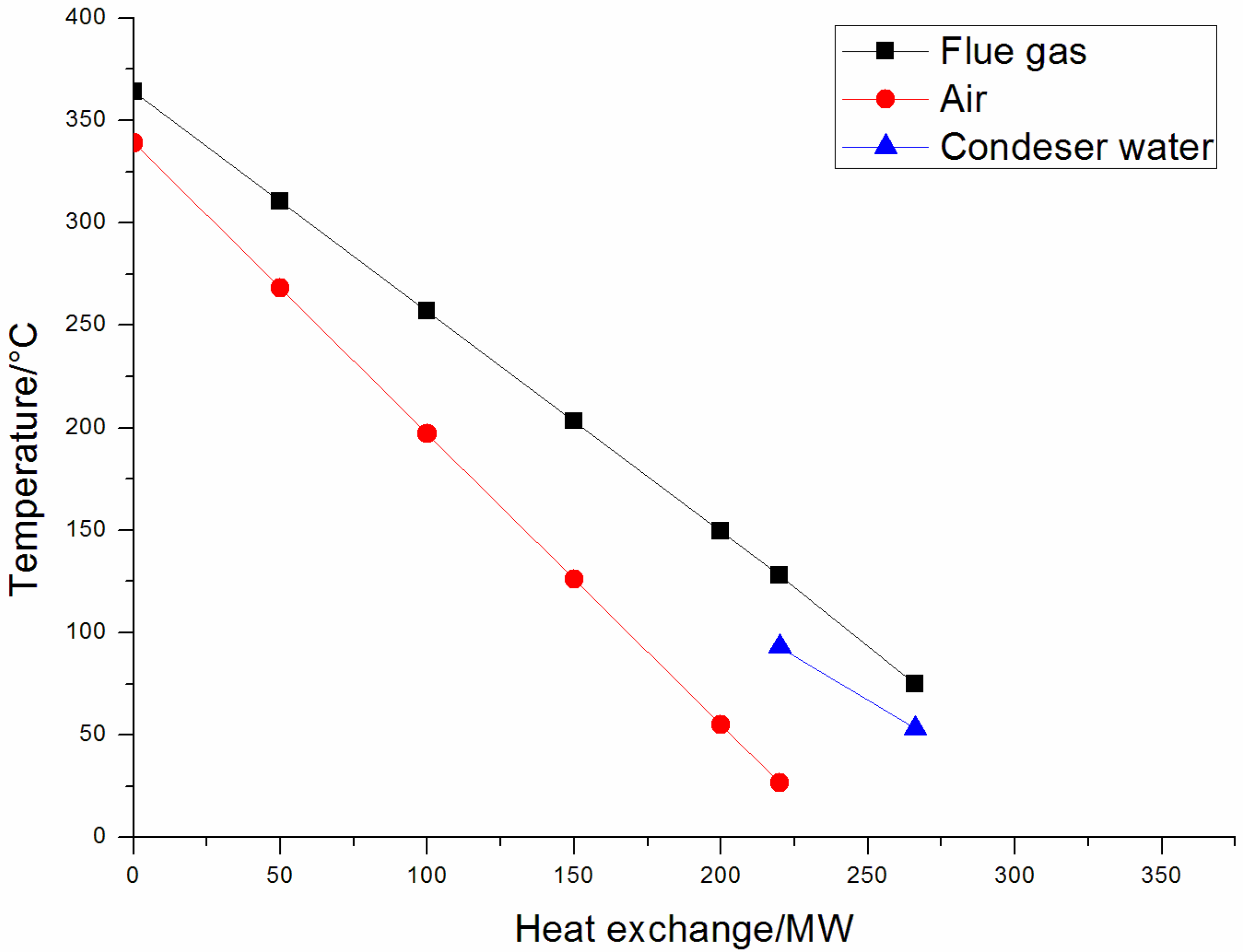
  • The heat transfer zone of the boiler-side AH is 25–360 °C, the hot end difference of the AH is 20–30 °C, and the cold end difference reaches up to 95 °C. The average heat exchange temperature difference is approximately 60 °C.
  • In the AH, as the heat exchange progresses, the heat exchange temperature difference between the air and flue gas continuously increases. The air outlet of the AH reaches a maximum, and the heat loss of the AH and exergy loss are large. Thus, the flue gas waste heat utilization system must be further improved.
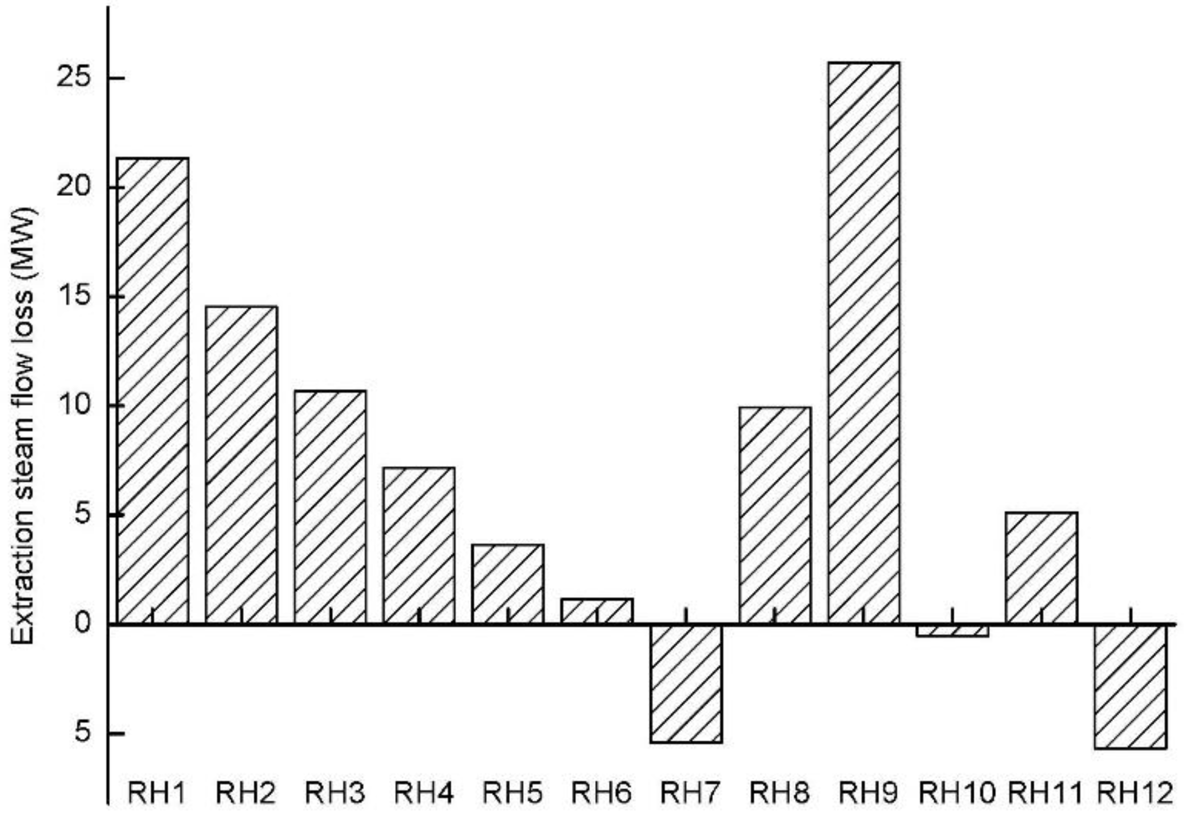
  • The air temperature at the outlet of the AH is low, i.e., only 120 °C, and can be used to reduce the extraction steam amounts of No. 10 RH and No. 11 RH. Because the steam from the No. 10 RH and No. 11 RH is unsaturated steam and the temperature is low, the reduction in the part extraction steam working ability is limited. The energy saving effect is not significant.

3.3. Boiler-Turbine Coupling Multi-Level Cascade Utilization System

Aiming at the limited energy saving effect of conventional waste heat utilization systems and the large heat exchange temperature difference at the AH outlet, a boiler-turbine coupling multi-level cascade utilization system was proposed, with no conditions against the heat transfer law or heat transfer limitations. The system is shown in Figure 3. The system uses the flue gas of the boiler side to heat the condensate of the turbine side. The condensate from the turbine reheating system heats the air in the AH inlet to reduce the heat exchange of the AH, exhausts part of the high-temperature flue gas, and heats part of the condensate in the turbine heat system. Therefore, the system increases the working of the unit under the condition that the main steam flow rate is constant.
From the perspective of heat transfer, the system solves the problem of the large heat exchange temperature difference and large exergy loss of the AH. Meanwhile, this system introduces the high-temperature flue gas into the reheating system to exchange heat with the feed water and condensate at the same level. In Figure 3, the new system introduces a cold air heating unit and flue gas bypass unit. The cold air heating unit is composed of two stages for condensation of the AHs in parallel. In this unit, the system heats the boiler inlet air with the high-energy-level condensate from the No. 10 RH outlet. After releasing heat, part of the condensate water flows into the flue gas bypass unit, exchanging heat with the higher-energy level flue gas, and then returns to the reheating system of the turbine. The heated air enters the AH and exchanges heat with the high-energy-level flue gas.
Because of the increasing inlet air temperature of the AH, the heat exchange amount between the air and flue gas is reduced compared to that of a conventional waste heat utilization system. The flue gas flow in the AH is reduced. Therefore, a flue gas bypass unit is added to the new multi-level cascade utilization system. In the new system, the economizer outlet flue gas is divided into two parts: the main AH flue gas and the AH bypass flue gas, and the flow ratio is 5.25:1.
In the new system, the main flue gas AH system is connected in series with the I LE, precipitators, a draft fan, the II LE, and a desulfurization tower. The flue gas bypass unit is composed of a first high-temperature heater and a second low-temperature heater. The flue gas bypass unit is connected in parallel with the main AH flue gas unit at the main AH inlet and at the first-stage LE outlet. The flue gas temperature decreases by gradient in the main system.
The desuperheated temperature water of the reheating system departs in three paths: one path comes from the feed water pump outlet, recovers the heat of the bypass first high-temperature heater, and returns to the economizer inlet; one path comes from the No. 8 RH inlet and I LE outlet condensate water system, exchanges heat with the flue gas in the second low-temperature bypass, and finally returns to the deaerator; and one path comes from the No. 11 RH inlet, passes the II LE, I LE, and front AH, and returns to the reheating system at the inlet of the deaerator.
The new system adopts the following process design to realize a deep cascade utilization of energy, and to improve the heat efficiency of the unit: (1) heating the same level of feed water with the high-temperature flue gas, and heating the same level of condensate water with low-temperature flue gas to realize the cascade utilization of energy; (2) dividing the boiler tail flue gas into main flue gas and bypass flue gas paths, wherein the main flue gas path passes through the I LE and II LE, and then transfers heat with the same-level condensate water; (3) arranging the front AH at the tail of the boiler, and using the condensed water at the inlet of the I LE to heat the low-temperature air to achieve the same level of heat exchange; (4) because of the increase of the air temperature at the inlet of the AH, the heat required for the air preheating process is reduced, and the flue gas flow of the AH is reduced, so part of the high-temperature flue gas is bypassed to exchange heat with the high-temperature feed water and low-temperature condensate water from the turbine side, reducing the extraction capacity of the steam turbine; and (5) decreasing the flue gas temperature away from the acid dew point of the tail gas, so that the rate of low-temperature corrosion in the tail heat exchange is reduced.

4. Energy Saving Analysis and Discussion of Multi-Level Cascade Utilization System in Ultra-Supercritical Unit

4.1. Boiler Island Energy Analysis

Table 4 provides the basic parameters of the boiler tail flue path. Figure 4 shows the heat transfer of the boiler island waste heat utilization system equipment. Figure 5 shows the comprehensive heat transfer of the new system. The following can be seen from Table 4 and Figure 5. First, in the new system, the I LE and II LE recover 93.7 MW of heat in total, the front AH consumes 73.3 MW of heat, and the high-temperature heater and low-temperature heater of the bypass flue path recover the total heat of 29.2 MW. Then, the new system recovers the total flue gas heat of 49.6 MW. Second, the traditional waste heat utilization system only sets the LE, without a bypass flue path. The heat recovery is 46.2 MW, i.e., 3.4 MW less than that of the new system. Third, according to the principle of energy cascade utilization, the new system performs the heat exchange between 361–215 °C for high-temperature period flue gas, and 190–334 °C for high-temperature period feed water; 215–167 °C for low-temperature flue gas and 140–170 °C for the period condensate water. The front AH in the 30–120 °C temperature period exchanges heat with the same temperature level of condensate water, i.e., 50–140 °C. In this way, it can match energy levels, and provide the maximum displacement of high- and low-level extraction steam, thus maximizing the guaranteed thermal power conversion efficiency.

4.2. Analysis of the Extraction Steam System of the Turbine Island

Figure 6 and Figure 7 show the effects of the new waste heat system on the steam extracting capacity and working ability at all stages of the turbine. Table 5 shows the basic parameters of the turbine side with the new waste heat utilization system. The working ability of the steam extraction varies with the steam flow. From Figure 6 and Figure 7, the following can be seen: (1) the high-temperature flue gas bypass discharges 22.51 t/h of steam from the 1–6 grade extraction steam; (2) the low-temperature flue gas bypass and I and II LEs discharge 40.25 t/h steam from 8–11 grade extraction steam; and (3) the ratio of the extraction steam variation between the high-pressure stage and low-pressure stage is 1:2, whereas the work variation ratio is 5:3. It can be seen that, for the steam turbine, the work ability of the high-pressure stage extraction steam is far greater than that of the low-pressure stage steam. Minimizing the high-pressure stage extraction steam can improve the steam turbine’s ability and reduce heat waste. The new system increases the unit working ability by 17.9 MW in total.

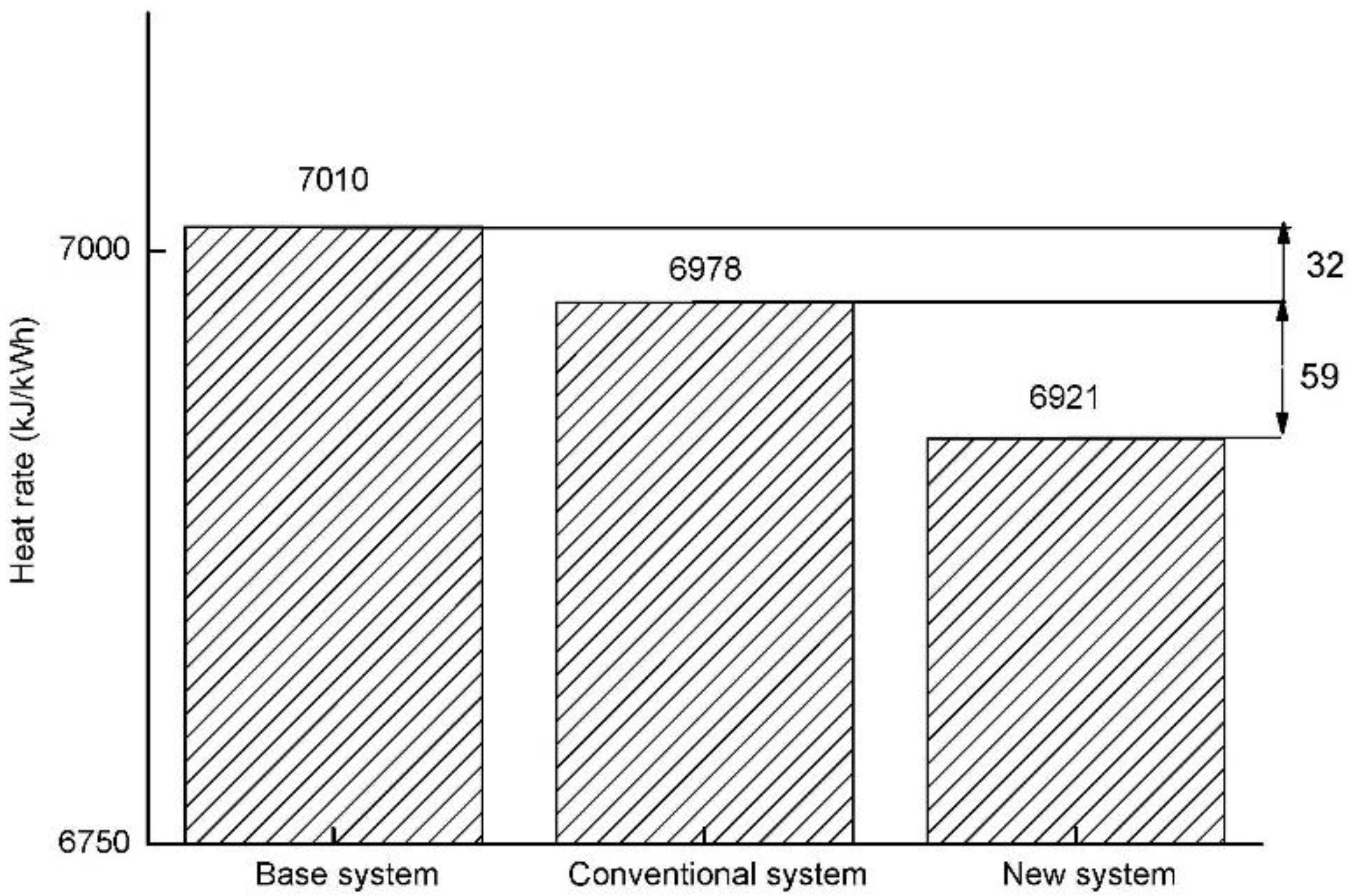
4.3. Techno-Economic Analysis

Specific techno-economic analyses of the new and basic cycles are conducted in this section. The new system was developed to improve efficiency, but requires an additional equipment investment. Meanwhile, the operation cost is correspondingly increased compared to the reference cycle. The basic economic assumptions are as follows. First, the assumed coal price, 119.4 USD/t, was the average cost for Chinese electric generators in 2015 [18], and the exchange rate was 6.8 CNY/USD. Second, the annual operation time was assumed to be 5500 h/year. Third, the operation and maintenance costs are fixed at 1.0% of the total plant investment (TPI) per year. Fourth, the interest rate (r) and service life of equipment (n) are 8% and 10 years, respectively [19,20]. Fifth, the grid price is 0.0589 USD/kWh. Sixth, the reference transformation unit is the basis.
Table 6 shows the techno-economic performance in all cases. The TPI of the base system (double-reheat 1000 MW system with no waste heat system) is standard in this paper. Owing to the cheap labor costs in China, the cost of a coal-fired power station is notably lower than those in Western countries, as described in the literature [21]. The TPIs of the conventional and new system increased by 4.7 million USD and 12.2 million USD, respectively, as compared with the basic system. The reason for the TPI increase in the conventional and new systems is the addition of the waste heat utilization equipment, such as the I LTE and II LTE. Moreover, these elements incur a low cost, as they are conventional equipment in the electricity industry in China [22,23].
The new system not only affects the thermal performance of the unit, but also affects the investment and economic value of the entire project. To perform a comprehensive evaluation of the new system, the annual total cost (AC) of the unit is defined as follows:
AC = ( CRF ) ( Total   plant   investment ) + ( Annual   O & M   cost ) + ( Annual   cost   of   fuel )
Here, CRF is the capital recovery factor; it is related to the discounted rate (I) and life of the equipment (n). CRF is calculated as CRF = [ I ( 1 + I ) n ] / [ ( 1 + I ) n 1 ] . Here, the discounted rate (I) and the life of equipment (n) are set to 4.9% and 10 years [24], respectively. Therefore, the CRF is equal to 0.129.
The AC of the conventional system decreases by 0.019 million USD per year compared with the basic system. As for new system, the AC decreases by 0.243 million USD per year, i.e., 0.224 million USD per year lower than the conventional system. In other words, the AC of the new system is the lowest of the three systems.
Several phenomena are suggested by Table 6 and Figure 8. First, under the premise that the investment in the new energy-saving system project is increased by 11.85 million USD, the heat rate of the new system is reduced by 91 kJ/kWh compared with the basic system and 59 kJ/kWh compared with the conventional system, but the AC per year decreases by 0.243 million USD. Second, owing to the introduction of the new equipment, the coal consumption of the unit is reduced by 3.3 g/kWh, and the power generation efficiency increased to 49.39%. Third, with reference to the static pay-back period method, the investment recovery period of the new unit is only 8.35 years, i.e., lower than the conventional system by 1.25 years. Although the initial investment is 2.6 times that of the conventional system, the recovery period is lower than that of the conventional system, and the economic benefits are significant.
In general, under the premise of limited investment and increased operation and maintenance costs, the new energy cascade utilization system has significant energy saving and consumption reduction effects and has evident economic and environmental benefits. It provides a good reference for energy saving and consumption reduction in large coal-fired units in China.

5. Conclusions

This study presented a boiler-turbine multi-level cascade utilization system for ultra-supercritical power plants, and facilitated the thermodynamic optimization of the system. To reveal the comprehensive effects of all of the optimization measures, thermodynamics, exergy, feasibility, and techno-economic analyses were conducted. The following results were obtained.
  • In terms of energy-saving, compared with the base system, for the new multi-level cascade heat utilization system, the decrement of the net heat rate is 91 kJ/kWh, the net efficiency increment is 0.79% and the decrement of net coal consumption is 3.3 g/kWh. In the new waste-heat saving system the thermal performance was significantly improved. For the conventional system, the decrement of net heat rate, the net efficiency increment, and net coal consumption decrement are 32 kJ/kWh, 0.4%, and 3.3 g/kWh, respectively.
  • In terms of thermal economy, the new system exhibits remarkable energy saving effects and a short investment recovery period. Compared with the base system, the static payback period of the new system is 8.35 years and the annual cost decreases by 0.232 million USD on the base of the total plant investment increasing by 1168 million USD. Compared with a conventional system, the total plant investment of the unit is 2.6 times and the static recovery period is only 0.87 times.
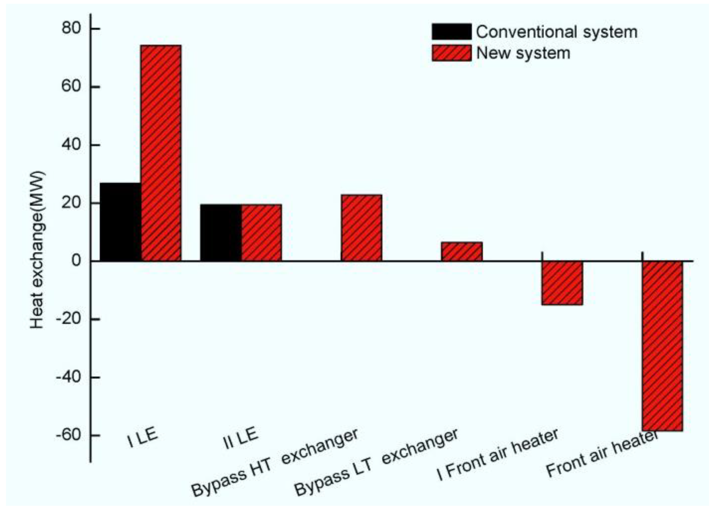
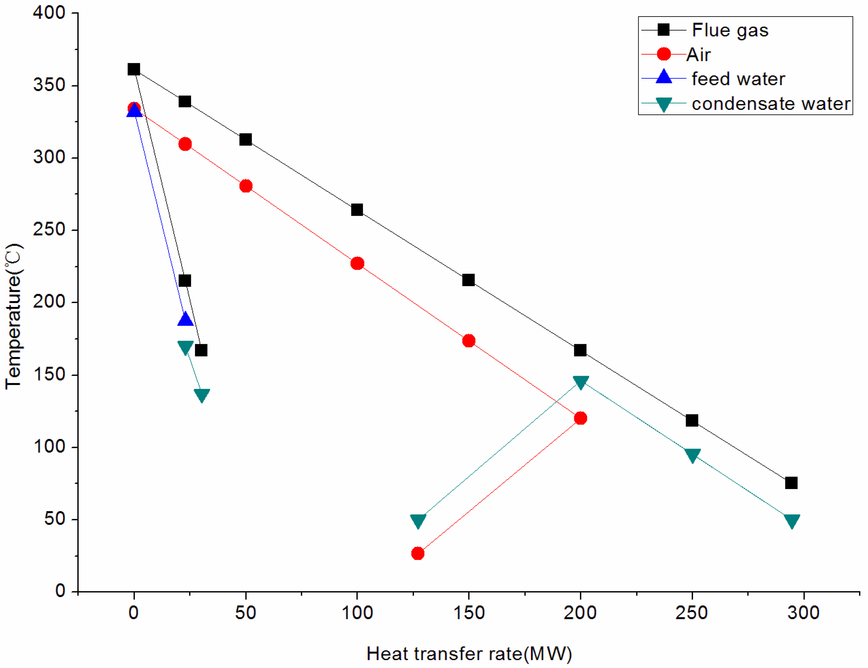
  • In the new waste-heat saving system the I LE inlet flue gas temperature is improved to 167 °C, 49 °C higher than the conventional system, which improves the heat exchange of the I LE by 47.5 MW. The energy saving of the flue gas bypass system is 29.2 MW. Due to heat exchange of the front air heater, the total energy-saving profit of the new system increased 3.4 MW compared with the conventional system. This result indicates that the comprehensive optimization of the waste heat utilization system is beneficial for the double reheat system because it provides significant benefits for the overall thermal performance and improves the techno-economic performance.

Author Contributions

Conceptualization, X.H. and Y.L.; Methodology, S.C. and T.L.; Software, S.C.; Validation, S.C., Y.L. and X.H.; Resources, X.H. and Y.L.; Data Curation, S.C. and Y.G.; Writing-Original Draft Preparation, S.C.; Writing-Review & Editing, S.C., Y.G. and T.L.; Supervision, T.L.; Project Administration, T.L. and X.H.; Funding Acquisition, T.L. and X.H. All authors have read and agreed to the published version of the manuscript.

Funding

This work was supported by the Shandong Electric Power Engineering Consulting Institute science and technology project (37-K2014-33).

Conflicts of Interest

The authors declare no conflict of interest.

References

  1. National Bureau of Statistics of the People’s Republic of China 2017 National Economic and Social Development Statistics Bulletin of China [EB/OL]. Available online: http://www.stats.gov.cn/tjsj/zxfb/201802/t20180228_1585631.html (accessed on 28 February 2018).
  2. Xu, S.X.; Wu, Z.X. Techincally Economical Analysis of Low Temperature Economizer Project of 1000 MW Unit. J. Shanghai Univ. Electr. Power 2014, 30, 94–100. [Google Scholar]
  3. Chen, L.; Sun, Y.Y.; Du, X.Z. Performance analysis of anti-corrosion heat exchangers made of special plastics for flue gas heat recovery. Proc. Chin. Soc. Electr. Eng. 2014, 34, 2778–2783. [Google Scholar]
  4. Wang, Z.P.; Chen, X.C.; Luo, T.K. Application of the WGGH in 1000MW Unit. Power Syst. Eng. 2017, 33, 46–48. [Google Scholar]
  5. Wen, Z.W.; Zhao, Z.L.; Gang, X.X. Research on Boiler Flue Gas Heat Recovery with Fluoroplastic Heat Exchangers. In Proceedings of the 2017 2nd International Conference on Energy, Power and Electrical Engineering (EPEE 2017), Shanghai, China, 26–27 November 2017; pp. 441–451. [Google Scholar]
  6. Zhang, Q.B.; Yang, J.G. Application study on enamel heat exchange tube in GGH of coal-fired unit with ultra-low flue gas emission. Therm. Power Gener. 2017, 46, 130–134. [Google Scholar]
  7. Li, Y.Y.; Han, Y.; Chen, Y.; Xu, G.; Yang, Y.P. A deep waste heat utilization system for utility boilers based on segmented air preheater design. Therm. Power Gener. 2016, 45, 41–47. [Google Scholar]
  8. Li, Y.Y.; Xu, G.; Xue, X.; Zheng, Q.Q.; Xu, C.; Yang, Y.P.; Key Laboratory of Condition Monitoring and Control for Power Plant Equipment of Ministry of Education. Thermodynamic analysis of the efficient flue gas waste heat utilization system with raw coal pre-dried of power plant. Proc. Chin. Soc. Electr. Eng. 2017, 37, 3498–3505. [Google Scholar]
  9. Han, Y.; Xu, G.; Yang, Y.P.; Xu, C.; Song, X. An optimized system for clean, efficient and deep utilization of flue gas waste heat from coal-fired power plants. J. Chin. Soc. Power Eng. 2015, 35, 674–680, 692. [Google Scholar]
  10. Han, Y.; Xu, G.; Yang, Y.P.; Li, Y. A Clean and Efficient Waste Heat Utilization System in Coal-fired Power Plants. Proc. Chin. Soc. Electr. Eng. 2016, 36, 5842–5848. [Google Scholar]
  11. Yue, Y.J.; Shen, S.L. Characteristics of European high-efficiency coal fired units and their implications for Chinese power plant. Electr. Power Constr. 2011, 32, 54–58. [Google Scholar]
  12. Song, J.H.; Kan, W.M.; Xu, C.; Xu, G.; Song, X.N. Comprehensive optimization of air preheater for boiler flue gas heat recovery. J. Chin. Soc. Power Eng. 2014, 34, 140–146. [Google Scholar]
  13. Shamsi, S.; Negash, A.; Cho, G.; Kim, Y.M. Waste Heat and Water Recovery System Optimization for Flue Gas in Thermal Power Plants. Sustainability 2019, 11, 1881. [Google Scholar] [CrossRef] [Green Version]
  14. Wang, Y.H.; Cao, L.; Li, X.C.; Wang, J.; Hu, P.; Li, B.; Li, Y. A novel thermodynamic method and insight of heat transfer characteristics on economizer for supercritical thermal power plant. Energy 2020, 191, 116573. [Google Scholar] [CrossRef]
  15. Zhao, Y.Z.; Pang, L.; Liang, X. Study on the Energy-saving Effect of Low-pressure Economizer System based on Energy Loss. J. Eng. Therm. Energy Power 2017, 32, 113–116. [Google Scholar]
  16. Xu, X.; Ju, G.D. Application and thermal economic analysis of plate low pressure economizer in flue gas waste heat recovery. In IOP Conference Series Earth and Environmental Science; IOP Publishing: Bristol, UK, 2019; Volume 291, p. 012025. [Google Scholar]
  17. Suresh, M.; Reddy, K.S.; Kolar, A.K. Thermodynamic optimization of advanced steam power plants retrofitted for oxy-coal combustion. J. Eng. Gas Turbines Power 2011, 133, 063001. [Google Scholar] [CrossRef]
  18. Ma, Y.F.; Yang, L.J.; Lu, J.F. Techno-economic comparison of boiler cold-end exhaust gas heat recovery processes for efficient brown-coal-fired power generation. Energy 2016, 116, 812–823. [Google Scholar] [CrossRef]
  19. Huang, B.; Xu, S.S.; Gao, S.W.; Liu, L.; Tao, J.; Niu, H.; Cai, M.; Cheng, J. Industrial test and techno-economic analysis of CO2 capture in Huaneng Beijing coal-fired power station. Appl. Energy 2010, 87, 3347–3354. [Google Scholar] [CrossRef]
  20. Liu, X.M. Engineering Economic Analysis; Peking University Press: Beijing, China, 2014. [Google Scholar]
  21. Hao, X.H. Comprehensive Waste Heat Utilization and Energy-Saving Analysis of the Low Temperature Flue Gas in Large-Scale Coal Fired Units. Ph.D. Thesis, North China Electricity Power University, Beijing, China, 2015. [Google Scholar]
  22. Electric Power Planning and Design Institute. Limitation Design Reference Cost Index of Thermal Power Engineering; China Electric Power Press: Beijing, China, 2009. [Google Scholar]
  23. Liu, Z.Z.; Li, Y.; Chen, X.H. Analysis of thermal economic benefits of first stage extraction location after reheat of reheat steam turbine set with outside steam cooler. Turbine Technol. 2004, 46, 382–384. [Google Scholar]
  24. Xu, G.; Jin, H.G.; Yang, Y.P.; Xu, Y.J.; Lin, H.; Duan, L.Q. A comprehensive techno-economic analysis method for power generation systems with CO2 capture. Int. J. Energy Res. 2010, 34, 321–332. [Google Scholar] [CrossRef]
Figure 1. Conventional waste heat utilization system.
Energies 13 03969 g001
Figure 2. Comprehensive heat transfer curve of the conventional system.
Energies 13 03969 g002
Figure 3. Furnace-coupled multi-level cascade utilization system.
Energies 13 03969 g003
Figure 4. Waste heat system heat exchange.
Energies 13 03969 g004
Figure 5. Comprehensive heat transfer curve of new system.
Energies 13 03969 g005
Figure 6. Extraction steam working increase.
Energies 13 03969 g006
Figure 7. Extraction steam flow loss.
Energies 13 03969 g007
Figure 8. Comparison of heat rates.
Energies 13 03969 g008
Table 1. Symbols and nomenclature in this paper.
Nomenclature
TMCRturbine maximum continuous ratingDEADeaerator
AHair heaterqHate rate (kJ/kWh)
CONcondenserbParameters of boiler superheater
RHRegenerative heaterpmass flow rate of steam (kg/s)
CPComprehensive power of the unitηpower generation efficiency
CAHCold air heaterhenthalpy
FGFlue gasQpower generation energy
LELow-temperature economizerwBoiler inlet feed water of boiler
Table 2. Main parameters of regenerative heaters.
ItemRH1RH2RH3RH4RH5RH6
Extraction steam temp. (°C)457.3412.4357.3303.3249.8205.1
Extraction steam enthalpy (kJ/kg)3201.8313830472956.828662778.4
Extraction steam flow t/h193.7188.5158.5133.67117.976.6
Outlet feed water tem. (°C)332.4308.7280.7253.4227.4202.1
Outlet feed water enthalpy (kJ/kg)1489.41367.61232.61106.5990.5880.2
Inlet feed water temp. (°C)308.7280.7253.4227.4202.1184.5
Inlet feed water enthalpy (kJ/kg)1367.61232.61106.5990.5880.2804.7
Drain water temp. (°C)314.3286.3259233207.7190.1
ItemDEARH8RH9RH10RH11RH12
Extraction steam temp. (°C)179.7148.9260.4180.9101.156.3
Extraction steam enthalpy (kJ/kg)26862568.2299028372684.92537.7
Extraction steam flow t/h72.692.767.466.15664
Outlet condensate water temp. (°C)177.5147122.710076.653.5
Outlet condensate water enthalpy (kJ/kg)752.1619.4517.6421.2323.6226.7
Inlet condensate water temp. (°C)147.4122.710076.653.530.3
Inlet condensate water enthalpy (kJ/kg)623.1517.6421.2323.6226.7517.6
Drain water tem. (°C)----105.6101.759.135.9
Table 3. Thermal parameters of heat exchange equipment at the tail of the boiler.
ItemI LEII LEAir Heater
Flue gas percent (%)100100100
Inlet flue gas temperature (°C)11895364
Outlet flue gas temperature (°C)9575118
Inlet water temperature (°C)7053--
Outlet water temperature (°C)9370--
Inlet air temperature (°C)----26.6
Outlet air temperature (°C)----229
Table 4. Thermal parameters of heat exchange equipment at the tail of the boiler.
ItemI/II LE (New System)Bypass HT ExchangerBypass LT ExchangerAir HeaterFront Air Heater
Flue gas percent (%)84161684--
Inlet flue gas temperature (°C)167/95361215361--
Outlet flue gas temperature (°C)90/75215167167--
Inlet water temperature (°C)70/53188.3140--145
Outlet water gas temperature (°C)169/70333170--50
Inlet air temperature (°C)------12030/25
Outlet air temperature (°C)------333120
Table 5. Main parameters of regenerative heaters.
ItemRH1RH2RH3RH4RH5RH6
Extraction steam temp. (°C)461.2416.9364.2312.1259.8209.3
Extraction steam enthalpy (kJ/kg)3208.63147.83060.62973.72884.92797.2
Extraction steam flow (t/h)172.34174147.8126.5114.375.4
Outlet feed water temp. (°C)332310283.2256.9231.6206.2
Outlet feed water enthalpy (kJ/kg)1487.61374.11244.51122.61008.8898.2
Inlet feed water temp. (°C)310283.2256.9231.6206.2188.3
Inlet feed water enthalpy (kJ/kg)1374.11244.51122.61008.8898.2821
Drain water temp. (°C)315.6288.8262.5237.2211.8193.9
ItemDEARH8RH9RH10RH11RH12
Extraction steam temp. (°C)183.4150262182.7102.957.3
Extraction steam enthalpy (kJ/kg)2703.52575.92993.92840.42688.22540.3
Extraction steam flow (t/h)7882.866.661.650.869.6
Outlet feed water temp. (°C)181.2148.1124101.277.854.4
Outlet feed water enthalpy (kJ/kg)768.3624523.1426.8328.4230.6
Inlet feed water temp. (°C)151.2124101.277.854.430.3
Inlet feed water enthalpy (kJ/kg)639.1523.1426.8328.4230.6129.9
Drain water tem. (°C)----106.8102.96035.9
Table 6. Techno-economic performance of each system.
Performance IndexBasic SystemConventional SystemNew System
Net efficiency (%)48.64949.39
Net heat rate (kJ/kWh)701069786921
Net coal consumption (g/kWh)252.8251.6249.5
Decrement (g/kWh)--−1.2−3.3
Annual coal cost saving (million USD)--−0.762−2.168
Operation and maintenance cost (O&M, million USD)--+0.0454+0.117
Total plant investment (million USD)--+4.54+11.68
Annual operating cost (million USD)--−0.605−1.738
Annual cost (AC, million USD/year)--−0.018−0.232
Static payback period (NAR, year)--9.68.35

