Article

Analysis of Dynamic Characteristics of Foreign Metal Objects under Electromagnetic Force in High-Power Wireless Power Transfer

Tianjin Key Laboratory of Advanced Electrical Engineering and Energy Technology, TianGong University, Tianjin 300387, China
*
Author to whom correspondence should be addressed.
Energies 2020, 13(15), 3881; https://doi.org/10.3390/en13153881
Submission received: 9 July 2020 / Revised: 24 July 2020 / Accepted: 27 July 2020 / Published: 30 July 2020
(This article belongs to the Special Issue Intelligent Wireless Power Transfer System and Its Application 2021)

Abstract

:
Because of the noncontact structure of wireless power transfer (WPT) systems, foreign metal objects can easily enter into the coupling region—and often move under the action of electromagnetic force (EMF), instead of staying relatively static, which brings a difficult problem for foreign object detection technology. In this paper, we investigate the motion state of foreign metal objects with different properties under the action of electromagnetic force in the coupling space of WPT system. The equivalent model of the circuit parameters with the intervention of foreign metal objects and the differential equations for the motion of foreign metal objects are derived. Combined with finite-element simulation calculations, the motion characteristic of ferromagnetic and non-ferromagnetic metals under EMF was analyzed. The results show that, due to the size and properties of the metal, non-ferromagnetic foreign metal objects have four states: vibration, suspension, static and flying out. The ferromagnetic foreign metal objects will adsorb on the coil surface and rapidly heat up. By establishing an experimental prototype, the analysis uses high-speed acquisition equipment to obtain the movement of foreign metal objects which verified the correctness of the simulation. This research is also beneficial to the operational safety and reliability of the WPT.

1. Introduction

With the rapid development of wireless power transfer (WPT), its remarkable flexibility, convenience and portability have been widely used in portable electronic devices, implantable medical devices, drones, smart homes and other fields [1,2,3,4,5]. It also provides noncontact power supply to special working conditions, such as oil wells, mud and explosion-proof environments. The battery power supply has a short life because of the limited capacity, and high-power equipment requires a large number of batteries, which also indicate the importance of WPT. Due to the problems of friction, corrosion, sparks, insulation and long-term exposure to harsh environments in traditional rail transit, the application of WPT technology to electric vehicles, high-speed rail trains and magnetic levitation trains has also become a research focus in recent years [6,7,8]. Moreover, considering the technical difficulties of high-power charging, pro-environmental and the limitations of mechanical connection systems in the ocean, WPT has also been applied to ship wireless high-power battery charging [9].
With the development of more applications, the rated power of WPT systems has been continuously increased from 3 kW to 100 kW or even higher [10]. For a metal material in a coupled magnetic field, it will be subjected to electromagnetic force (EMF) due to the eddy current effect or magnetization effect of the magnetic field [11,12]. With the improvement of power, the increase of excitation current and spatial coupling magnetic field will enhance the EMF of metal objects. Therefore, EMF in high-power WPT systems cannot be ignored. The research on EMF is mainly focused on the problems of vibration, noise and mechanical deformation of traditional electrical equipment. In addition, it has also been widely used in electromagnetic forming [13,14], electromagnetic ejection [15,16] and magnetic levitation technology [17]. Synergy of melting wave and electromagnetic force on the transition mechanism is studied in reference [18] that the mutual promotion of melt waves and EMF may cause the surface of the conductor to ablate and generate flashes and smokes, which will greatly reduce the safety performance of the equipment. A study [19] proposed to use multiple staggered AC and DC coils to provide both electrical and mechanical energy for micro-robots. This system consists of a pair of external AC and DC staggered coils and a pair of coils located inside the micro-robot. The two internal coils are used, respectively to receive electrical energy and to generate propulsion as an electromagnet.
However, WPT use space magnetic field coupling for power transmission. The noncontact structural characteristics of the transmitting coil and the receiving coil make the WPT system vulnerable to interference by foreign metal objects during the operation [20]. To date, most of the studies on foreign metal objects focus on the detection of foreign objects and the impact on the performance of WPT systems. For the foreign body detection methods, one of the studied methods is to place additional coil sets with different structure between the transmitting coil and receiving coil, thereby determining the presence and location of foreign objects by obtaining the changes of parameter of the coil sets [21,22,23]. One of the studied method is reducing the quality factor of the secondary coil [24].In reference [25], a prototype of an electric vehicle capacitive WPT system was built to study the effect of different foreign objects on the system performance when they approached the coupling mechanism from the outside. It is found that when the distance between the foreign body and the coupling mechanism is less than three centimeters, the system performance will be significantly affected. However, there have been few studies that explores the relative displacement of metal foreign bodies entering the coupling space of the WPT system under the action of EMF. Metal foreign bodies under EMF may bring danger to surrounding organisms and WPT systems.
In this paper, the characteristics of directional movement of metal foreign bodies under the EMF are studied on the basis of the high-power WPT system. The paper is organized as follows: Section 2 establishes the equivalent parameter model of the circuit and the differential equations of motion of the metal foreign body subjected to EMF, based on the virtual displacement method. The finite-element simulation is used to analyze the longitudinal and horizontal motion of different types of metals under the action of EMF in Section 3. In Section 4, an experimental prototype is built to verify the correctness of the characteristics. Section 5 draws conclusions about this paper.

2. Equivalent Model of Circuit Parameters and Differential Equations of Motion

Foreign metal objects can be divided into non-ferromagnetic metals and ferromagnetic metals according to their own electromagnetic parameters such as electrical conductivity σ and relative permeability μ. In order to investigate the dynamic parameters such as induced current I, the electromagnetic force of foreign metal object F, motion displacement x , its speed dx/dt and acceleration d2x/d2t, the circuit parameters will be introduced into analysis and the nonlinear differential equations will be used to characterize the dynamic process of metal foreign bodies under EMF.

2.1. Equivalent Model of Circuit Parameters

For non-ferromagnetic foreign metal objects such as aluminum and copper, it should be considered that the skin effect in high-frequency circuits, which means the induced current in the metal is concentrated in the thin layer on the surface of the metal. Metal foreign bodies can be equivalent to multiple concentric energized toroidal coils, as shown in Figure 1.
Induced current i 1 p   (p = 1, 2, …, N 1 ) in each current ring can be derived from the electromagnetic field equation. According to the mutual inductance definition formula between the two coils, the mutual inductance M between the qth turn of the coupling coil and the pth turn of the equivalent current ring of the foreign metal object can be further obtained as:
M q p = μ 0 r 0 q r 1 p [ ( 2 k k ) B ( k ) 2 k E ( k ) ]
where μ 0 is the vacuum permeability,   k = 2 r 0 q r 1 p x m 2 + ( r 0 q + r 1 p ) 2 , B ( k ) = 0 π 2 d α 1 k 2 s i n 2 α , E ( k ) = 0 π 2 1 k 2 s i n 2 α d α , x m is the displacement of the non-ferromagnetic foreign metal object relative to the coupling coil,   r 0 q is the radius of the qth turn of the coupling coil and the r 1 p is the radius of the pth turn of the equivalent current ring of the foreign metal object. Then the derivative of the mutual inductance M with respect to the displacement x m is:
d M q p d x m = 2 x m μ 0 r 0 q r 1 p [ x m 2 + ( r 0 q + r 1 p ) 2 ] 3 2 0 π 2 c o s 2 φ ( 1 k 2 s i n 2 α ) 3 2 d α
According to the principle of virtual displacement, the electromagnetic repulsion force F of non-ferromagnetic metal foreign bodies can be further expressed as:
F = q = 1 N 0 p = 1 N 1 i 0 i 1 p d M q p d x m
where i0 is the coupling coil current.
For ferromagnetic metal—when entering the WPT system—it will not only generate induced eddy currents under the action of space magnetic field, but also generate molecular magnetization current due to magnetization, EMF cannot be directly solved by the induced current, thus magnetic common energy is introduced to calculate the electromagnetic attraction. The definition of magnetic common energy W m is:
W m ( i , x ) = i = 1 n i i ψ i W m ( ψ , x ) = i = 1 n 0 i 1 ψ i d i i
where ψ is the magnetic linkage of the magnetic coupling system, which is a function of current i and displacement x . When a ferromagnetic foreign metal object produces a virtual displacement dx, the energy conservation principle can be written as:
d W m = i = 1 n ψ i d i i + F d x = i = 1 n W m i i d i i + W m x d x
where W m i i = ψ i , the EMF of the ferromagnetic metal can be represented as (6), which pointing the direction that the magnetic common energy tends to the maximum at constant current, in the same direction as electromagnetic attraction:
F = W m x
From (3) and (6), we can obtain the expression of EMF of metal in coupled magnetic field, which is a function of current and displacement:
F = F x + F y = f ( i , x )

2.2. Differential Equations of Motion

In general, the dynamic process of foreign metal objects under the influence of EMF can be expressed by nonlinear differential equations. The voltage equation of the coupling coil is given by:
u = i 0 R + d ψ d t
where u is the alternating power supply voltage, i0 is the coupling coil current and both are a function of time t. R is the resistance of coil circuit.
From Newton’s second law and the law of conservation we derived the motion equation of non-ferromagnetic metals as (9), the foreign metal object will move in multiple directions, as there is an angular difference between the direction of the EMF and the direction of the magnetic field and the direction vector is e θ × B :
{ (9) m d 2 x d t 2 = F J x m g F f ( x ) F f ( d x d t ) (10) m d 2 y d t 2 = F J y F f ( y ) F f ( d y d t )
where FJx and FJy are the components of the electromagnetic repulsive force in the coupling directions of the coil and in the horizontal, respectively. x and y are the longitudinal and horizontal displacements of the metal, as shown in Figure 1. Ff(x) and Ff(y) are the reaction force related to displacement in longitudinal and horizontal, such as frictional force during movement, Ff (dx/dt) and Ff (dy/dt) are the reaction force related to speed in longitudinal and horizontal, for instance, resistance in air.
For a ferromagnetic foreign metal object, since it is only subjected to the electromagnetic attraction force FM in the longitudinal direction, its motion equation can be expressed as:
m d 2 x d t 2 = F M + m g F f ( x ) F f ( d x d t )
By combining the simultaneous Equations (7)–(10), we can obtain the differential equation set of motion for metal objects. It is composed of EMF equation, current equation of coupled coil, longitudinal motion equation along the coupling direction and horizontal motion equation along the coil surface direction. Due to the interaction of the variables during the motion, finite-element analysis is used for simulation.

3. Finite-Element Simulation

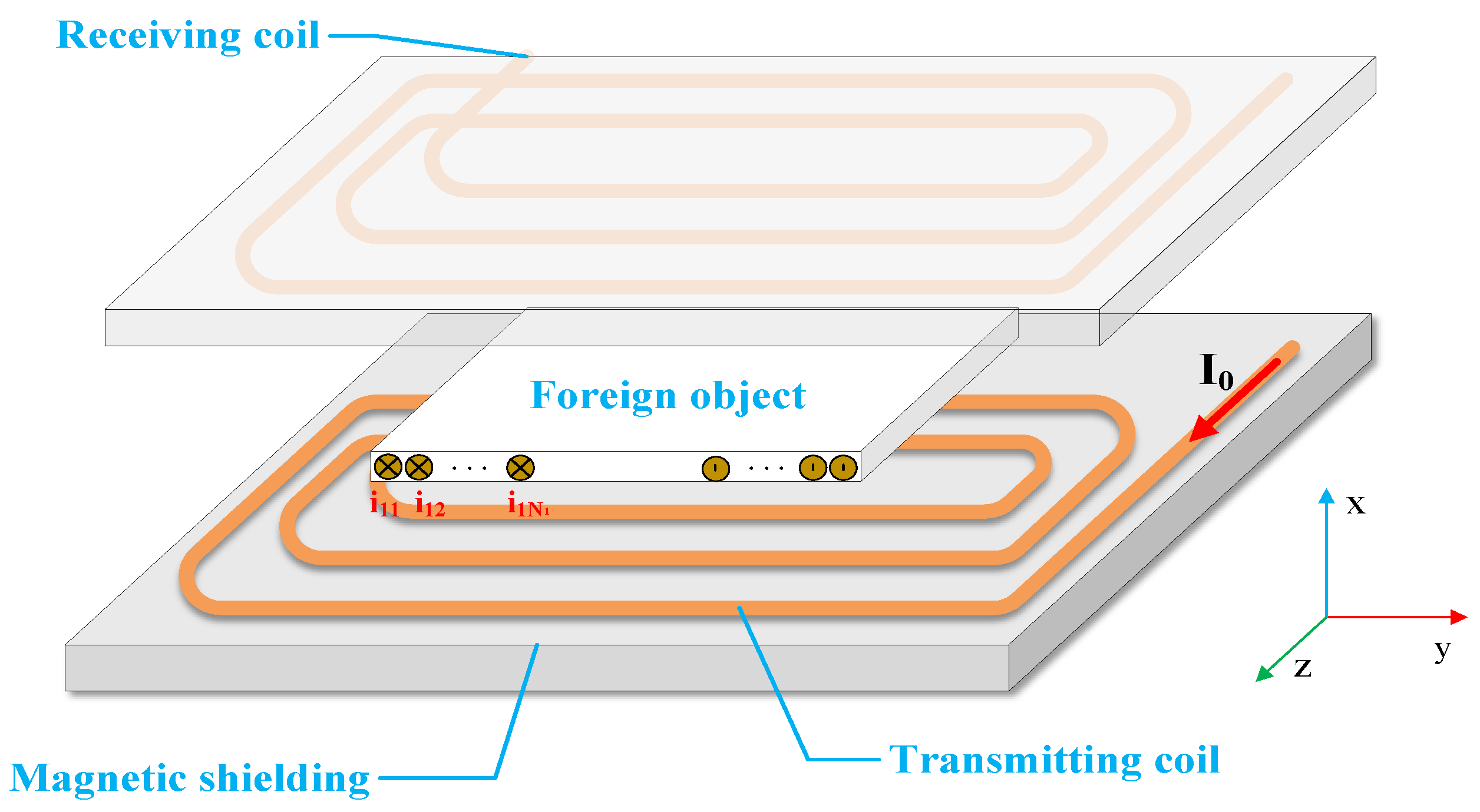
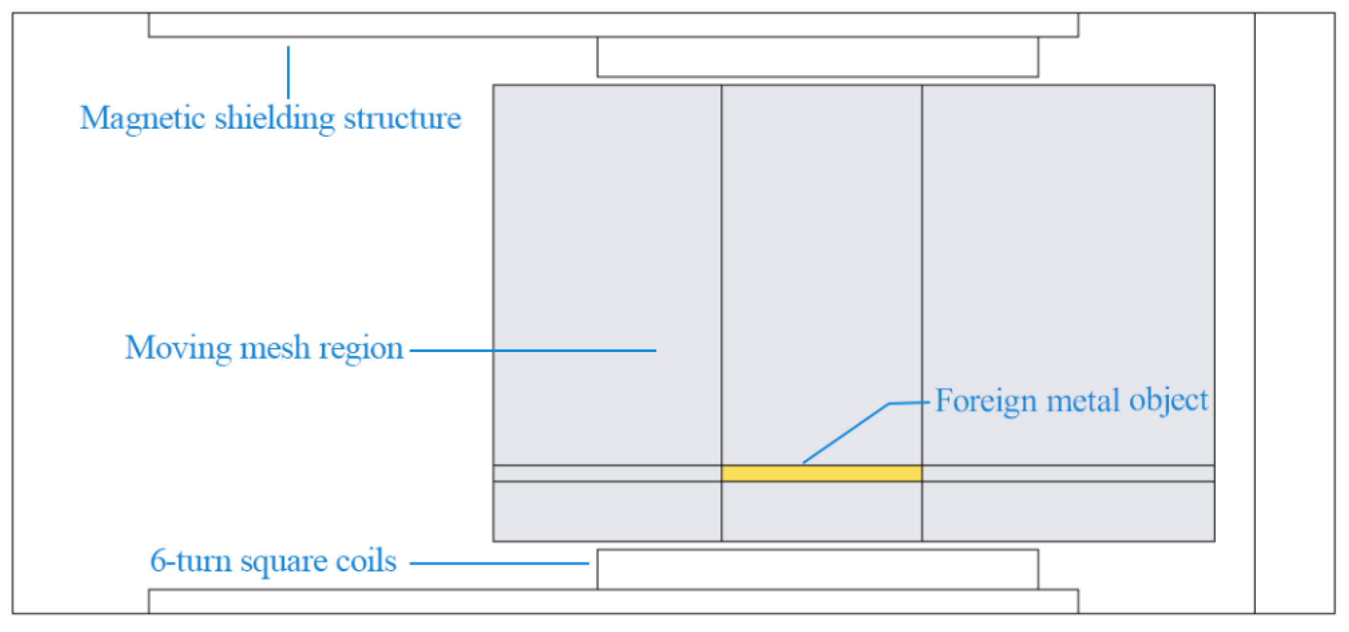
In order to further explore the motion characteristics of foreign metal object in different parameters, a simulation calculation model was established by finite-element analysis software—COMSOL Multiphysics as shown in Figure 2. Both transmitting and receiving coils are 6-turn square coils with a size of 46.4 × 46.4 cm2. The exciting current of the system is 171A, and the resonance frequency is 10 kHz. For the purpose of concentrating the magnetic field to get the best transmission efficiency, the coil is embedded in the E-type magnetic shielding structure to reduce leakage in space magnetic field.
In the process of calculating the dynamic characteristics of metal foreign bodies in the time-varying electromagnetic field, time-domain simulation is required. As the skin effect in high-frequency circuits cannot be neglected, in this paper, the boundary layer meshing method is used to analyze the induced current and electromagnetic force of the conductor in the time domain. We use the differential equations of motion derived in the Section 2 and moving mesh to simulate the dynamic part of the foreign metal object. According to the different electrical parameters of metals, we choose three commonly used metals: aluminum, copper and iron for analysis. The characteristics of metal materials are listed in Table 1.

3.1. Analysis of Longitudinal Dynamic Characteristics of Metal

Figure 2 shows that the system is axisymmetric, and the metal object is placed in the center of the coil. Hence, we selected a half of the simulation model with metal foreign bodies to calculate the magnetic field and induced eddy current—and consequently to get a more detailed mesh—which can also improve the accuracy and convergence speed of the transient solution.
In order to investigate the longitudinal dynamic characteristics of the non-ferromagnetic metal, we analyzed the movement of the 50 × 50 × 2 mm
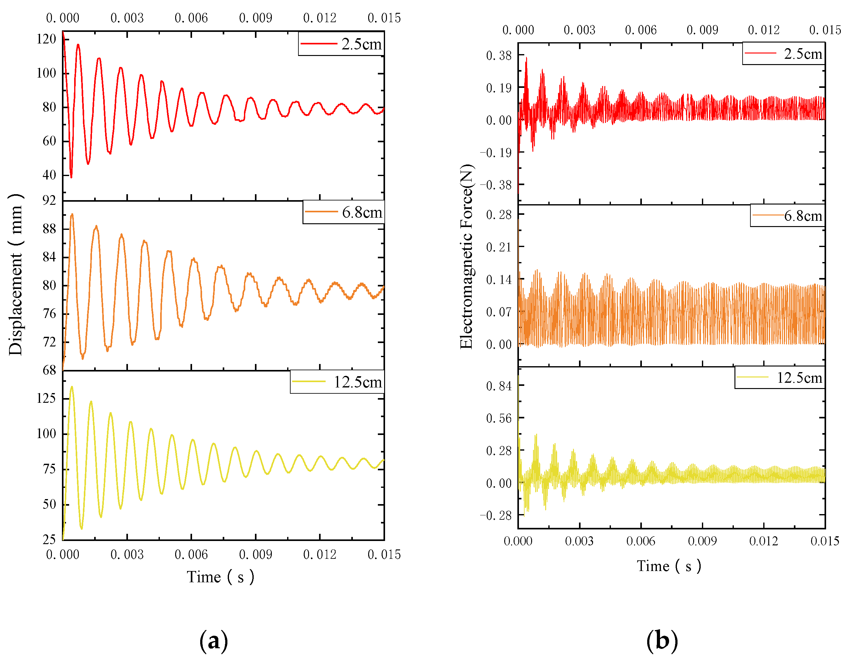
3 -sized aluminum sheet after it enters the system by different initial positions. The transmission distance is set to 15 cm according to the actual chassis height of the electric vehicle or high-speed rail; the movable range of foreign metal objects in the longitudinal space is set to 1.8 cm–13.2 cm; the transient solution time is 150 cycles. When the initial entry position of the aluminum sheet is 2.5 cm, 6.8 cm and 12.5 cm, it is close to the transmitting coil, the intermediate position and the receiving coil, respectively. 
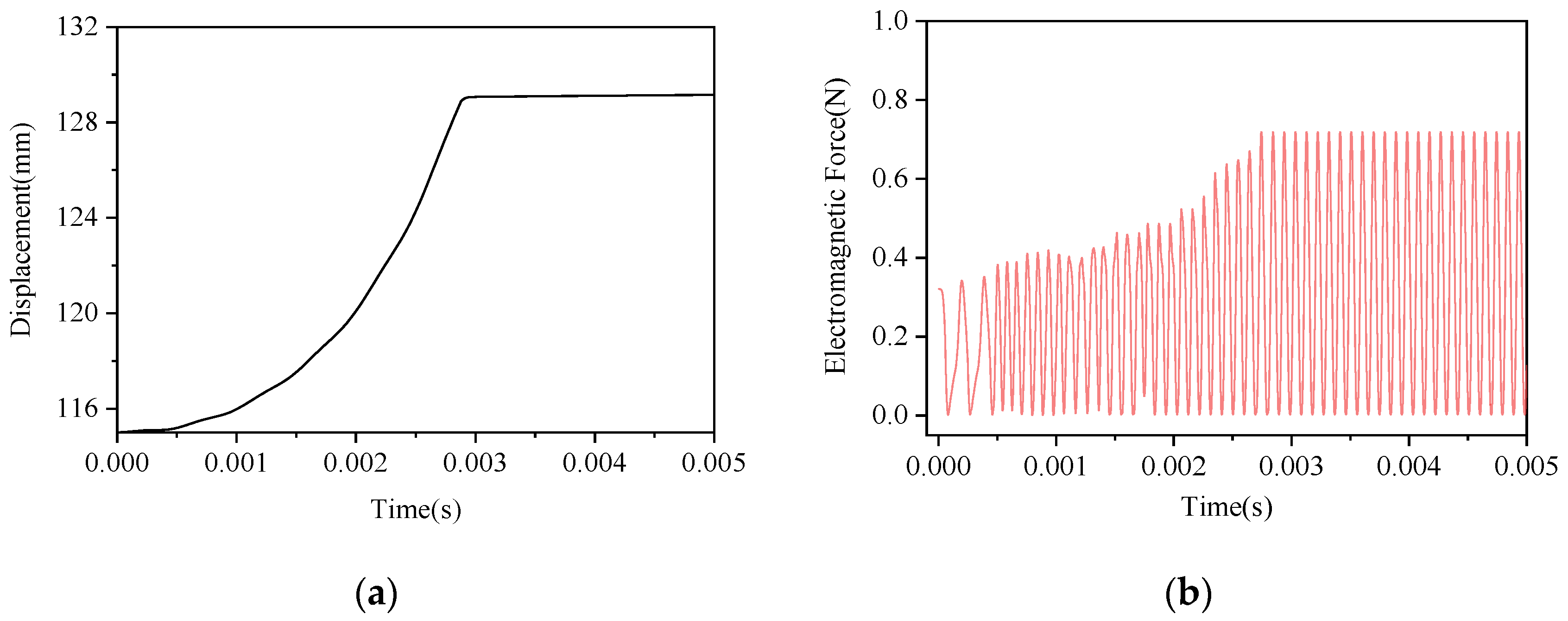
Figure 3 shows EMF and displacement at different initial positions.
When entering the spatial coupling area, due to electromagnetic repulsive, the aluminum sheet will move from the initial position be away from the coil, meanwhile, the rapid attenuation of EMF will make acceleration decrease gradually. With the balance of gravity and steady-state component of EMF, the displacement of the aluminum sheet gradually decreases, resulting in a damped oscillation process and eventually stabilized at the position of 78 mm, 79 mm and 82 mm positions, separately. By this time, the aluminum sheet has reached a relative stability, which can be regarded as a stable state. This shows that the entered position has less influence on the final stable position, however, it will affect the time of reaching stability and the movement state of metal foreign body. The closer the initial position is to the stable position, the faster the final equilibrium will be reached. When the initial position is 68 mm, metal only takes 0.009 s to achieve stability.
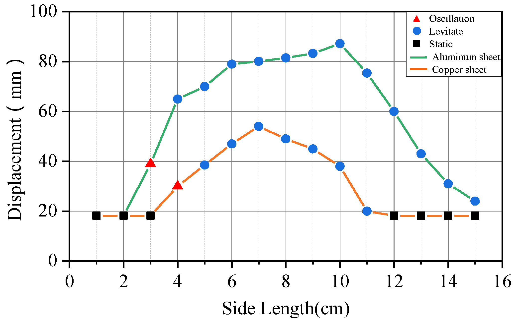
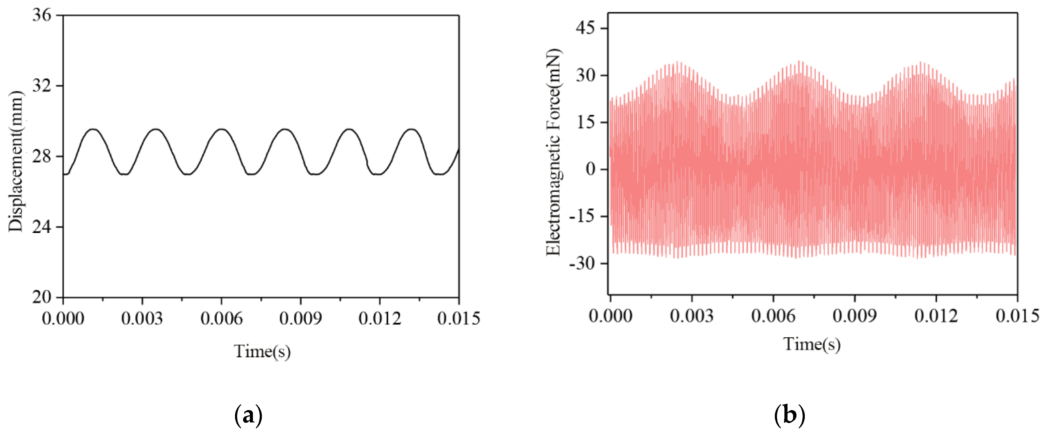
By analyzing aluminum and copper sheets of different sizes, we found that non-ferromagnetic metals have three motion states in longitudinal direction after entering a spatially coupled magnetic field of WPT system, as shown in Figure 4. For the metal, different side lengths and densities will cause different values of EMF and gravity, and thus impact on final steady-state position. To sum up, the motion state of non-ferromagnetic metal foreign body is related to its own electromagnetic parameters, size and weight, that is, it mainly depends on whether the EMF applied to the metal foreign body during the exercise can finally balance with gravity.
For ferromagnetic foreign matter, it is easily adsorbed on the surface of the coupling coil by electromagnetic attraction in the system. When the iron is close to the transmitting coil, the electromagnetic attraction is in the same direction as gravity, which increases the acceleration of its downward movement. The iron will quickly fall on the transmitting coil and be further attracted to the surface of the transmitting coil. When the iron keeps close to the receiving coil, it is subject to upward electromagnetic attraction. If the electromagnetic attraction force is larger than gravity, the iron will move upward and eventually adsorb on the surface of the receiving coil. As shown in Figure 5, the iron piece in an initial position of 11.5 cm is subjected to the upward electromagnetic attraction, and it only takes 0.028 s to reach 12.8 cm where the receiving coil is. Ferromagnetic metal is easily magnetized and generates induced eddy current, its adsorption on the surface of the coil will quickly cause the rise of local temperature, power loss and high-frequency noise, which will impact the transmission efficiency, the operational safety and reliability of the WPT.

3.2. Analysis of Horizontal Dynamic Characteristics of Metal

From the derivation analysis in Section 2, we know that the horizontal EMF on metal foreign bodies, entering the WPT system, is much smaller than the longitudinal EMF. Hence, it can be ignored in most cases. However, for the non-ferromagnetic metals, they will oscillate or suspend in the air. By this time, the horizontal EMF will cause a lateral movement of metal, may even fly out of the coupling area, which will affect the external safety. Figure 6 shows the horizontal EMF and lateral displacement of a copper sheet with the length of 5 cm and the horizontal initial position is at 27 cm in the middle of the coil.
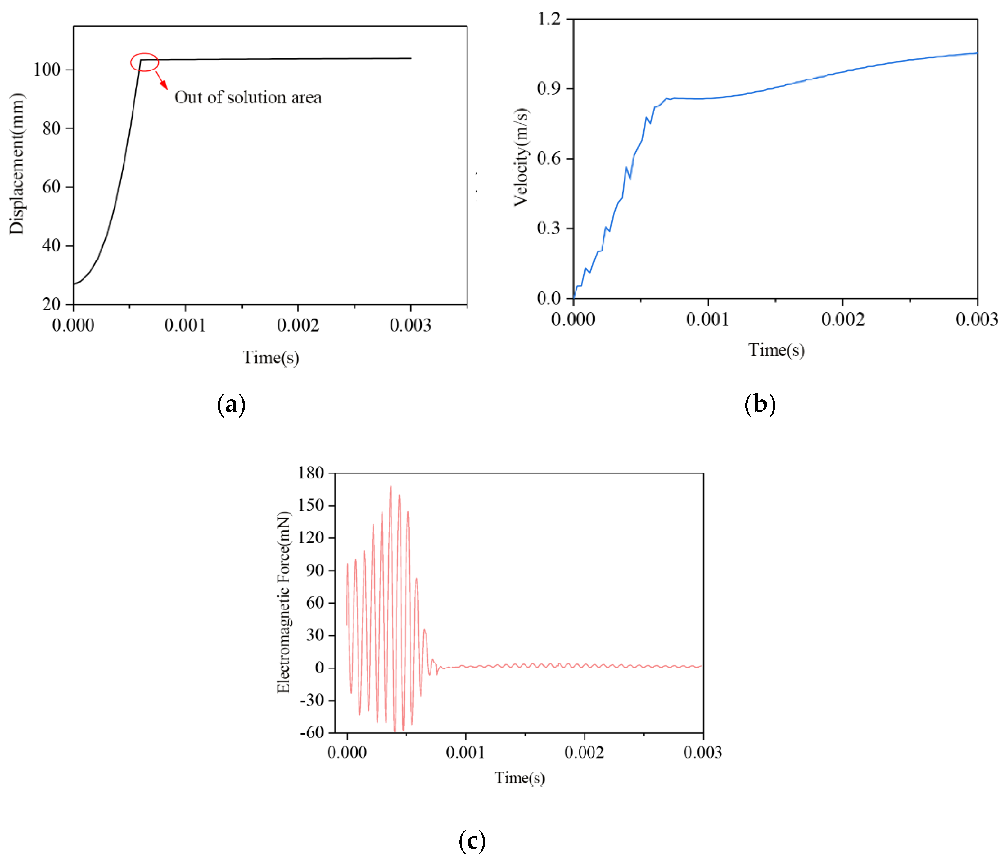
For metals with lower density such as aluminum, when it is large and thin, the effect of horizontal EMF will be very obvious. We calculated the displacement and EMF in the horizontal direction of the aluminum sheet with a size of 100 × 100 × 1 mm3 as shown in Figure 7. The EMF of aluminum sheet in the initial state is 37 mN, the direction is pointing out of the coil, and as the metal moves outward, the EMF gradually increases. The aluminum sheet takes around 1 ms to leave the coupling area of the system where the velocity is 0.82 m/s, as shown in Figure 7. The horizontal EMF gradually decreases to 0 after leaving the coupling area.

4. Experiment and Discussion

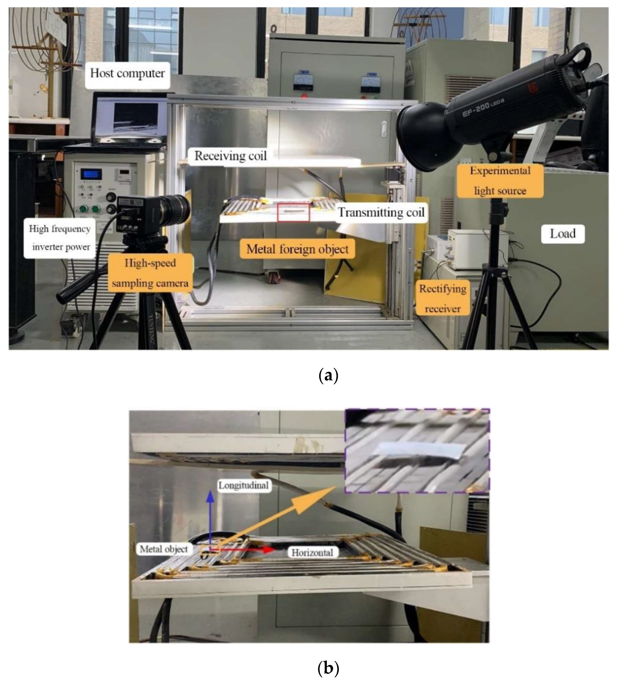
In this section, an isometric experimental prototype is built to verify the dynamic characteristics of metal foreign bodies as shown in Figure 8 and initial power of the system is 5 kW. In order to display the motion trajectory and characteristics of metal objects intuitively, in this experiment, we used high-speed sampling camera to track and measure the movement of metal and analyze the motion characteristics of the objects according to the change in acceleration.
The direction coordinates and initial position of metal in the coil are shown in 
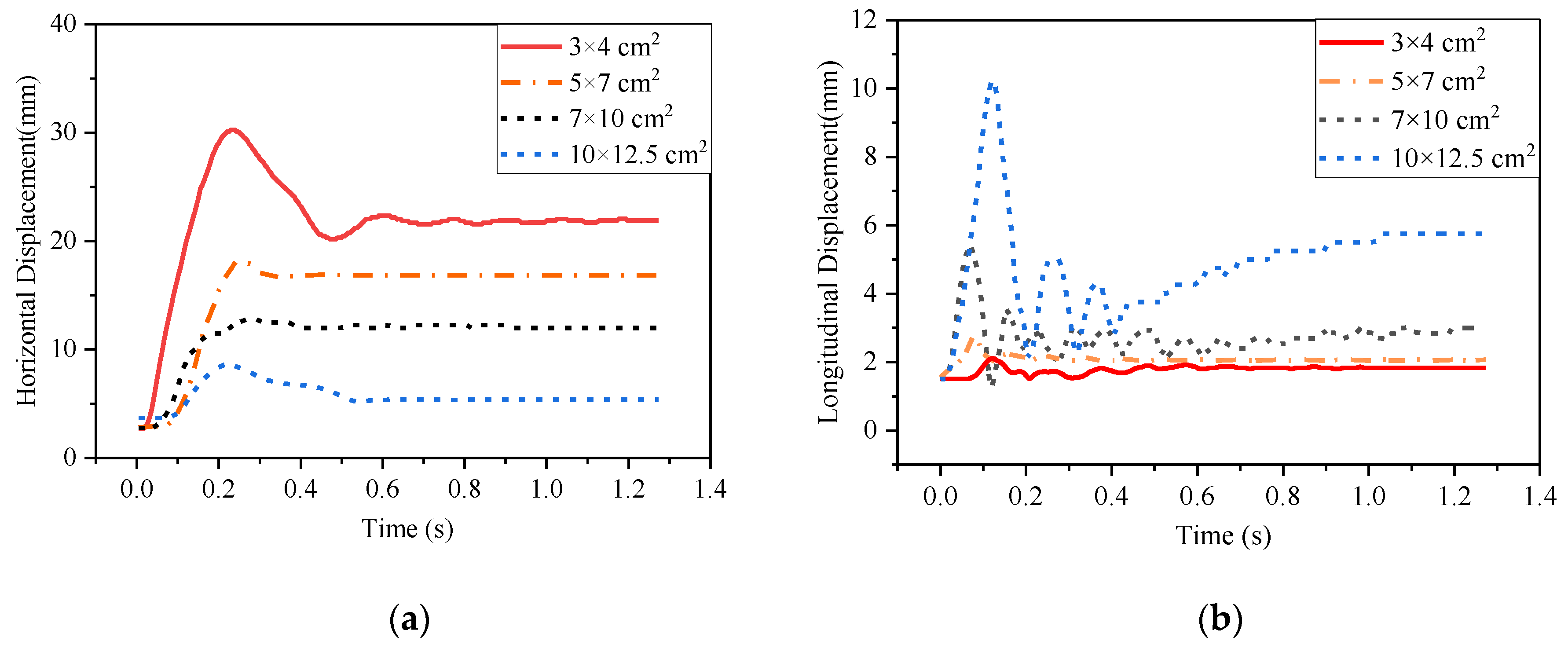
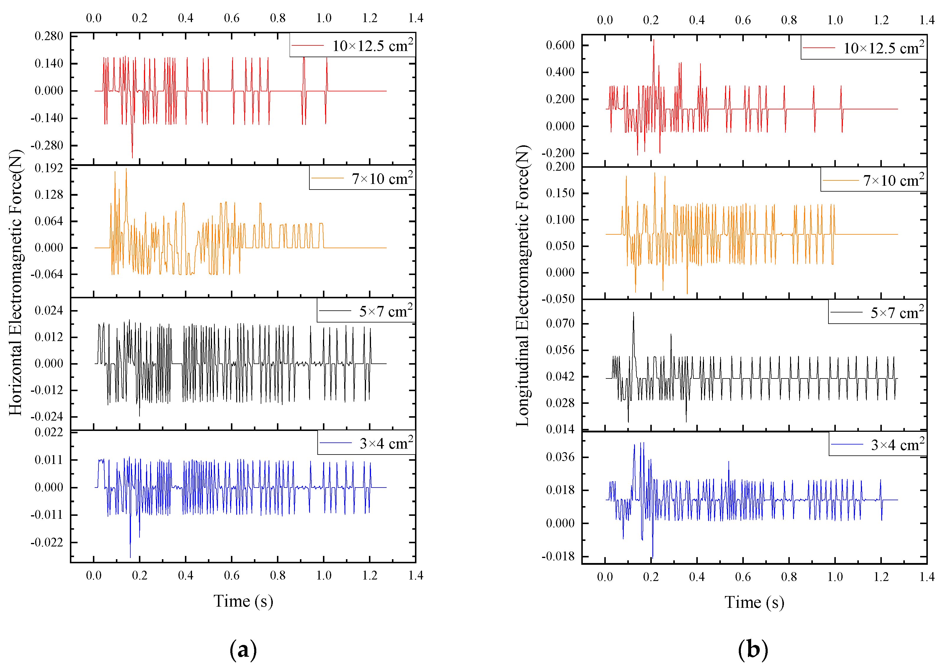
Figure 8b. By analyzing the movement trajectory of the metal foreign body, we obtained that the displacements and EMF of the aluminum sheets with dimensions of 3 × 4 cm2, 5 × 7 cm2, 7 × 10 cm2 and 10 × 12.5 cm2 in different directions in Figure 9 and Figure 10.
As we can see in Figure 9—under the action of the horizontal EMF—the aluminum sheets have a positive displacement in the horizontal direction, that is, it moves from the outside of the coil to the middle position of the coil, and the displacement finally becomes a constant and forms a stable state. Relatively, the 3 × 4 cm2 aluminum sheet is greatly affected by EMF due to its light weight. It will oscillate and finally stabilizes at 22.5 mm which is the middle position of the coil. It is consistent with the suspension state obtained in the simulation, which proves that the simulation is correct.
From Figure 10, when the size of the aluminum sheet is increased to 10 × 12.5 cm2, the increasing amplitudes of horizontal and longitudinal EMF are more obvious. Like the longitudinal movement, as the size of the aluminum sheet increases, the longitudinal EMF will enhance rapidly and be greater than the increase of its own gravity. When the suspended position of the 10 × 12.5 cm2-sized aluminum sheet is at 5.7 mm, the acceleration of the upward movement reaches to maximum, which is consistent with the conclusions obtained in the simulation calculation.
According to the simulation analysis above, both the horizontal and longitudinal EMF of aluminum flakes increases with the area. Thereinto, the augment of longitudinal EMF is more obvious. When the side length of aluminum sheet is longer than coil width, the longitudinal EMF is large. As part of it is in the outside of the coil, the horizontal EMF is unevenly distributed, which will cause the aluminum sheet to fly out of the system. The experimental results are consistent with the simulation.
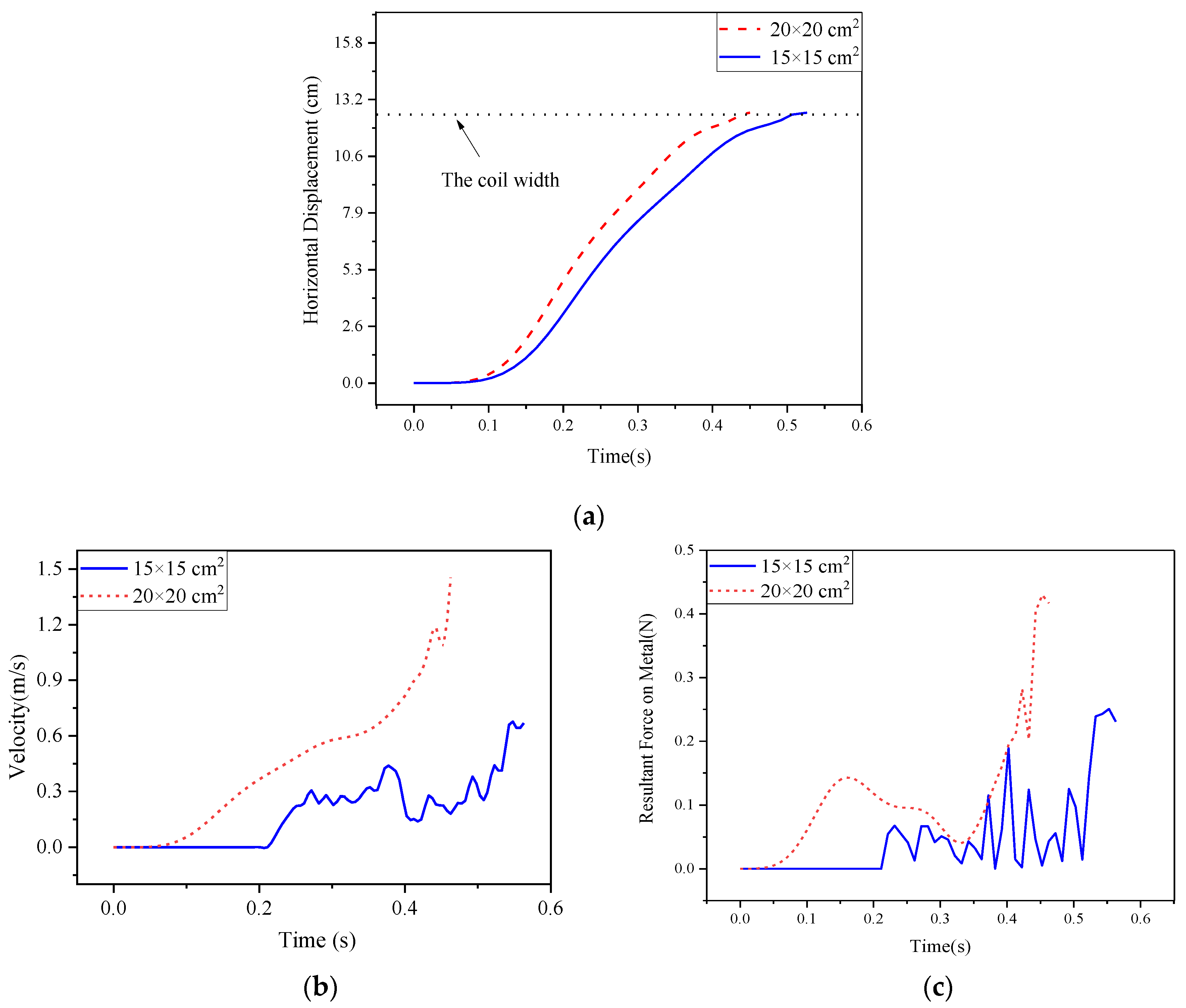
Horizontal displacement, velocity and resultant force are shown in Figure 11 when aluminum sheets with size of 15 × 15 cm2 and 20 × 20 cm2 fly out. The enhance of velocity of the 20 × 20 cm2 aluminum sheet is more obvious, and it will fly out of the system in only 0.45 s. The 15 × 15 cm2 aluminum sheet has a smaller EMF, and the fluctuation of resultant force is obvious. It requires 0.52 s to fly out. In addition, the speeds of the two aluminum sheets are 0.67 m/s and 1.46 m/s, respectively. This indicates that the speed of flying out of the system is related positively to the size of the aluminum sheet.
A similar study was performed on the copper sheets with the same size, and we found that the copper sheet and aluminum sheet were subjected to similar EMF, while the difference of density is large. Therefore, after entering the system, the dynamic characteristics of the copper sheet are not obvious, basically remained stationary and only affect the power and transmission efficiency of the system.
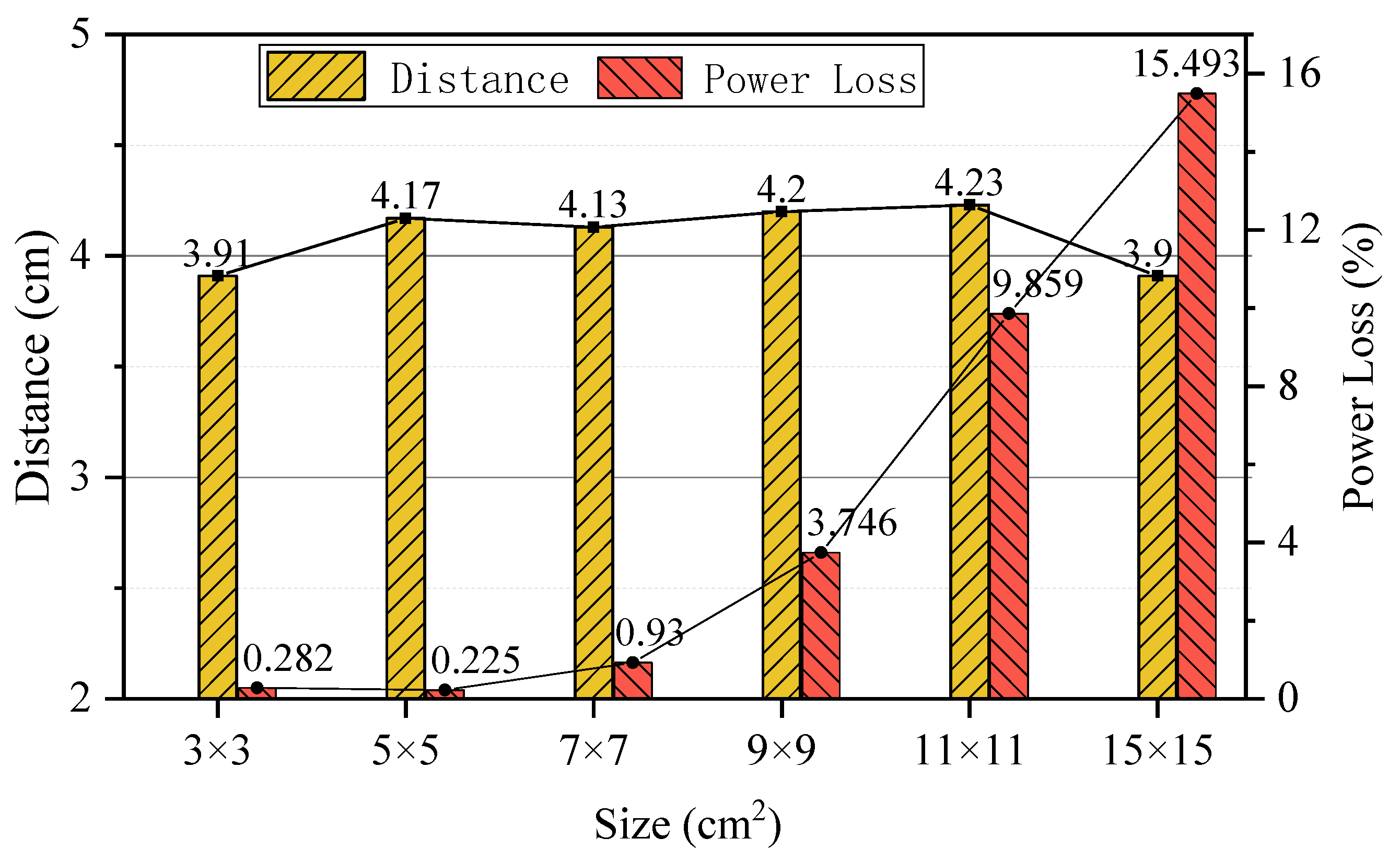
According to the simulation results, ferromagnetic objects only move longitudinally under the electromagnetic attraction. Because the electromagnetic attraction near the transmitting coil is not easy to display, the dynamic characteristics of the ferromagnetic metal around the receiving coil are analyzed. The initial position of iron sheet is the middle position of the transmission distance, gradually raise the iron piece and measure the distance that the iron piece can be completely attracted by the receiving coil, the results are consistent with simulation, as shown in Figure 12, which also shows the power loss of the system during the iron sheet being adsorbed.
As the size of the iron piece gradually increases, the distance that iron pieces can be adsorbed shows an increasing trend, which means that the resultant force of electromagnetic attraction and gravity gradually increases. However, for an iron piece of 5 × 5 cm2, considering that the power loss of the system is slightly reduced while the space magnetic field is more concentrated, the distance that the piece of iron can be adsorbed increases slightly to 4.17 cm. For a 15 × 15 cm2 piece of iron that is wider than the coil, when the iron piece is rapidly magnetized to generate a large amount of eddy current loss, the power loss of the system can reach 15.493%. Simultaneously, the space magnetic field is attenuated, which reduces the enhance of the electromagnetic attraction force. The adsorption distance dropped to 3.9 cm.
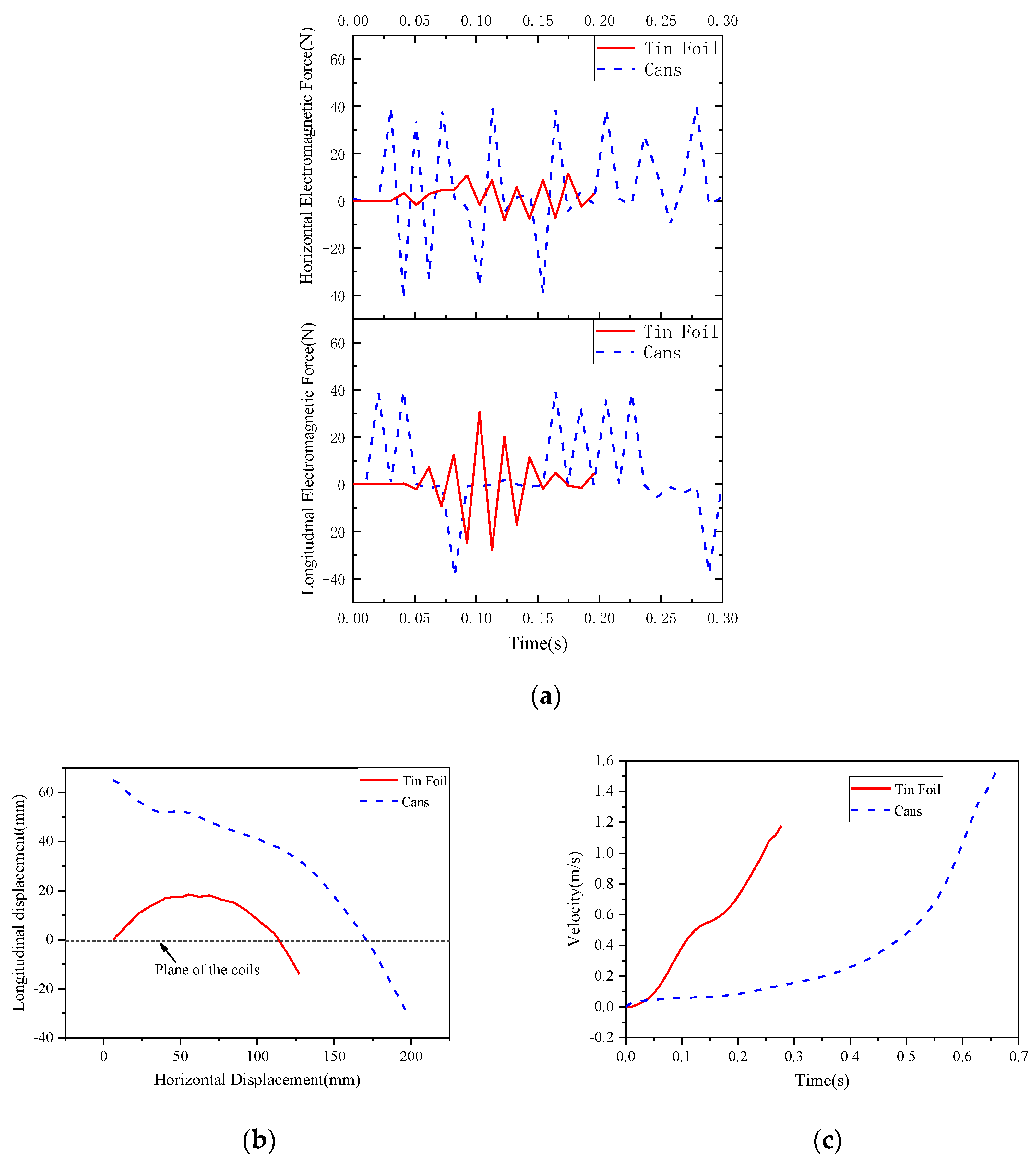
In order to further study the effect of foreign metal objects on the system security under the effect of EMF. we measured and analyzed some common foreign metal objects mentioned in SAE J2954 standard [26], such as paper clips, coins, tin foil and cans. The results are shown in Table 2 and Figure 13.
It can be seen from Table 2 that paper clips and coins of different denominations will be attracted to the coil surface by electromagnetic attraction and cause a power loss. Figure 13 shows that aluminum packaging such as cans and foils are subject to electromagnetic repulsion and flying out of the system, because they are thinner and wider than the coil of the system. The speed of the foil and cans flying out of the system can reach 1.17 m/s and 1.53 m/s, respectively, which will bring hidden danger to the external environment of the system.

5. Conclusions

By combining the dynamic equation with the EMF equation, the force and motion characteristics of metal foreign bodies with different electrical parameters at different positions in the high-power WPT system are studied using simulation and experiments. Non-ferromagnetic metal is subject to electromagnetic repulsion in the system and an oscillating state will occur during the equilibrium process of EMF and gravity. When the side length of the aluminum sheet is in the range of 4 cm–15 cm, and the side length of the copper sheet is in the range of 5 cm–11 cm, the oscillation will gradually decay, and finally remain suspended in the coupling space. While metals larger than the coupling coil will be easily ejected from the system because of the uneven EMF, it takes only 0.45 s for the 20 × 20 cm2 aluminum sheet to fly out of the system and the speed reaches 1.46 m/s. After entering the system, ferromagnetic foreign metal objects are easily attracted to the surface of the coil by electromagnetic attraction and generate heat rapidly, which affects the transmission efficiency of the system. When an iron piece with a size of 15 × 15 cm2 enters the system, the power loss is 15.493%, which seriously affects the safety of the system.

Author Contributions

The study was written by X.Z. and Y.R. and revised by X.N. and F.W. The project was conceived, planned and supervised by L.S. and Q.Y. All authors have contributed to the editing and proofreading of this study. All authors have read and agreed to the published version of the manuscript.

Funding

This research was funded by the National Natural Science Foundation of China under Grant 51977147, Grant 51807138 and Grant 51677132.

Conflicts of Interest

The authors declare no conflicts of interest.

References

  1. Liu, Y.; Li, B.; Huang, M.; Chen, Z.; Zhang, X. An Overview of Regulation Topologies in Resonant Wireless Power Transfer Systems for Consumer Electronics or Bio-Implants. Energies 2018, 11, 1737. [Google Scholar] [CrossRef] [Green Version]
  2. Zhang, Z.; Pang, H.; Georgiadis, A.; Cecati, C. Wireless Power Transfer-An Overview. IEEE Trans. Ind. Electron. 2019, 66, 1044–1058. [Google Scholar] [CrossRef]
  3. Park, J.; Kim, J.; Kim, S.; Cheong, W.; Jang, J.; Park, Y.; Na, K.; Kim, Y.; Heo, J.; Lee, C.; et al. Soft, smart contact lenses with integrations of wireless circuits, glucose sensors, and displays. Sci. Adv. 2018, 4, eaap9841. [Google Scholar] [CrossRef] [PubMed] [Green Version]
  4. Xu, J.; Zeng, Y.; Zhang, R. UAV-Enabled Wireless Power Transfer: Trajectory Design and Energy Optimization. IEEE Trans. Wirel. Commun. 2018, 17, 5092–5106. [Google Scholar] [CrossRef] [Green Version]
  5. Lu, Y.; Ma, D. Wireless Power Transfer System Architectures for Portable or Implantable Applications. Energies 2016, 9, 1087. [Google Scholar] [CrossRef]
  6. Kim, J.; Lee, B.; Lee, J.; Lee, S.; Park, C.; Jung, S.; Lee, S.; Yi, K.; Baek, J. Development of 1-MW Inductive Power Transfer System for a High-Speed Train. IEEE Trans. Ind. Electron. 2015, 62, 6242–6250. [Google Scholar] [CrossRef]
  7. Li, S.; Mi, C. Wireless Power Transfer for Electric Vehicle Applications. IEEE J. Emerg. Sel. Top. Power Electron. 2015, 3, 4–17. [Google Scholar]
  8. Hui, S. Planar Wireless Charging Technology for Portable Electronic Products and Qi. Proc. IEEE 2013, 101, 1290–1301. [Google Scholar] [CrossRef] [Green Version]
  9. Guidi, G.; Suul, J.A.; Jenset, F.; Sorfonn, I. Wireless Charging for Ships: High-Power Inductive Charging for Battery Electric and Plug-In Hybrid Vessels. IEEE Electrif. Mag. 2017, 5, 22–32. [Google Scholar] [CrossRef]
  10. Covic, G.A.; Boys, J.T. Modern trends in inductive power transfer for transportation applications. IEEE J. Emerg. Sel. Top. Power Electron. 2013, 1, 28–41. [Google Scholar] [CrossRef]
  11. Zhang, X.; Ni, X.; Wei, B.; Wang, S.; Yang, Q. Characteristic Analysis of Electromagnetic Force in a High-Power Wireless Power Transfer System. Energies 2018, 11, 3088. [Google Scholar] [CrossRef] [Green Version]
  12. Ron Hui, S.Y. Technical and safety challenges in emerging trends of near-field wireless power transfer industrial guidelines. IEEE Electromagn. Compat. Mag. 2018, 7, 78–86. [Google Scholar]
  13. Tomura, S.; Kunieda, M. Analysis of electromagnetic force in wire-EDM. Precis. Eng. 2009, 33, 255–262. [Google Scholar] [CrossRef]
  14. Lai, Z.; Cao, Q.; Zhang, B.; Han, X.; Zhou, Z.; Xiong, Q.; Zhang, X.; Chen, Q.; Li, L. Radial Lorentz force augmented deep drawing for large drawing ratio using a novel dual-coil electromagnetic forming system. J. Mater. Process. Technol. 2015, 222, 13–20. [Google Scholar] [CrossRef]
  15. Kou, B.; Huang, X.; Wu, H.; Li, L. Thrust and Thermal Characteristics of Electromagnetic Launcher Based on Permanent Magnet Linear Synchronous Motors. IEEE Trans. Magn. 2009, 45, 358–362. [Google Scholar]
  16. Yang, Y.; Hu, S.; Chen, W.; Gao, Y.; Tian, Y.; Li, M. Analysis of Force and Velocity on the Projectile During the Electromagnetic Railgun Launching Process. In Proceedings of the 2013 International Forum on Special Equipments and Engineering Mechanics, Nanjing, China, 11 July 2013; pp. 6–9. [Google Scholar]
  17. Park, Y. Design and implementation of an electromagnetic levitation system for active magnetic bearing wheels. IET Control Theory Appl. 2014, 8, 139–148. [Google Scholar] [CrossRef]
  18. Tang, B.; Xu, Y.; Lin, Q.; Li, B. Synergy of Melt-Wave and Electromagnetic Force on the Transition Mechanism in Electromagnetic Launch. IEEE Trans. Plasma Sci. 2017, 45, 1361–1367. [Google Scholar] [CrossRef]
  19. Kim, D.; Hwang, K.; Park, J.; Park, H.; Ahn, S. High-Efficiency Wireless Power and Force Transfer for a Micro-Robot Using a Multiaxis AC/DC Magnetic Coil. IEEE Trans. Magn. 2017, 53, 1–4. [Google Scholar] [CrossRef]
  20. Tan, L.; Li, J.; Chen, C.; Yan, C.; Guo, J.; Huang, X. Analysis and Performance Improvement of WPT Systems in the Environment of Single Non-Ferromagnetic Metal Plates. Energies 2016, 9, 576. [Google Scholar] [CrossRef] [Green Version]
  21. Xiang, L.; Zhu, Z.; Tian, J.; Tian, Y. Foreign Object Detection in a Wireless Power Transfer System Using Symmetrical Coil Sets. IEEE Access 2019, 7, 44622–44631. [Google Scholar] [CrossRef]
  22. Jeong, S.; Kwak, H.; Jang, G.; Choi, S.; Rim, C. Dual-Purpose Nonoverlapping Coil Sets as Metal Object and Vehicle Position Detections for Wireless Stationary EV Chargers. IEEE Trans. Power Electron. 2018, 33, 7387–7397. [Google Scholar] [CrossRef]
  23. Cheng, B.; Lu, J.; Zhang, Y.; Pan, G.; Chabaan, R.; Mi, C. A Metal Object Detection System with Multilayer Detection Coil Layouts for Electric Vehicle Wireless Charging. Energies 2020, 13, 2960. [Google Scholar] [CrossRef]
  24. Fukuda, S.; Nakano, H.; Murayama, Y.; Murakami, T.; Kozakai, O.; Fujimaki, K. A Novel Metal Detector Using the Quality Factor of the Secondary Coil for Wireless Power Transfer Systems. In Proceedings of the 2012 IEEE MTT-S International Microwave Workshop Series on Innovative Wireless Power Transmission: Technologies, Systems, and Applications, IMWS-IWPT 2012, Kyoto, Japan, 10–11 May 2012. [Google Scholar]
  25. Regensburger, B.; Kumar, A.; Sinha, S.; Afridi, K. Impact of Foreign Objects on the Performance of Capacitive Wireless Charging Systems for Electric Vehicles. In Proceedings of the 2018 IEEE Transportation Electrification Conference and Expo (ITEC), Long Beach, CA, USA, 30 August 2018. [Google Scholar]
  26. J2954B: Wireless Power Transfer for Light-Duty Plug-in/Electric Vehicles and Alignment Methodology-SAE International. Available online: https://www.sae.org/standards/content/j2954_201904/ (accessed on 28 July 2020).
Figure 1. Equivalent model of eddy current in non-ferromagnetic object.
Energies 13 03881 g001
Figure 2. Finite-element solution model for dynamic characteristic of foreign metal objects.
Energies 13 03881 g002
Figure 3. Steady state of foreign metal objects at different initial positions. (a) Longitudinal displacement; (b) longitudinal electromagnetic force (EMF).
Energies 13 03881 g003
Figure 4. Movement and position of aluminum and copper sheets under different sizes.
Energies 13 03881 g004
Figure 5. Displacement and force of iron object under electromagnetic attraction. (a) Longitudinal displacement; (b) longitudinal EMF.
Energies 13 03881 g005
Figure 6. Displacement and force of iron object under electromagnetic attraction. (a) Horizontal displacement; (b) horizontal EMF.
Energies 13 03881 g006
Figure 7. Dynamic parameters of non-ferromagnetic metals in horizontal flight state. (a) Horizontal displacement; (b) velocity of metal; (c) horizontal EMF.
Energies 13 03881 g007
Figure 8. Prototype of the high-power WPT system and data acquisition device. (a) Experiment platform; (b) schematic of metal foreign bodies.
Energies 13 03881 g008
Figure 9. Movement displacement of four sizes of aluminum sheets. (a) Horizontal displacement of aluminum sheets; (b) longitudinal displacement of aluminum sheets.
Energies 13 03881 g009
Figure 10. Electromagnetic force changes of four sizes of aluminum sheets. (a) Horizontal EMF of aluminum sheets; (b) longitudinal EMF of aluminum sheets.
Energies 13 03881 g010
Figure 11. Horizontal displacement, velocity and resultant force changes when aluminum flies out. (a) Horizontal displacement; (b) velocity; (c) resultant force.
Energies 13 03881 g011
Figure 12. Distance and power loss of different size iron absorbed by the receiving coil.
Energies 13 03881 g012
Figure 13. Dynamic characteristics of foil paper and cans. (a) EMF; (b) movement path; (c) velocity.
Energies 13 03881 g013
Table 1. Parameters of the metal.
MaterialConductivity σ (S/m)Permeability μ
Non-ferromagneticAluminum3.774 × 1071
Copper5.998 × 1071
FerromagneticIron1.12 × 1074000
Table 2. Basic parameters and force of common foreign metal objects.
Foreign Metal ObjectsMaterialSize (mm) Mass   ( 10 3 kg ) Affected by EMF
paper clipiron wire30 × 81Electromagnetic attraction; adsorption distance: 1 cm; power loss: 0.724%.
1 dime coinstainless steeldiameter: 19; thickness: 1.5.2.5Electromagnetic attraction; adsorption distance: 0.75 cm; power loss: 0.971%.
5 dime coinsteel core copper-plated alloydiameter: 20.5; thickness: 1.65.3.8Electromagnetic attraction; adsorption distance: 0.7 cm; power loss: 1.437%.
1 yuan coinnickel-plated steel corediameter: 25; thickness: 1.85.6.05Electromagnetic attraction; adsorption distance: 0.5 cm; power loss: 2.874%.

