Article

Transient Pressure Analysis of a Multiple Fractured Well in a Stress-Sensitive Coal Seam Gas Reservoir

1
State Key Laboratory of Oil and Gas Reservoir Geology and Exploitation, Southwest Petroleum University, Chengdu 610500, China
2
Department of Chemical Engineering, College of Engineering and Applied Science, University of Wyoming, 1000 E. University Avenue, Laramie, WY 82071-2000, USA
*
Authors to whom correspondence should be addressed.
Energies 2020, 13(15), 3849; https://doi.org/10.3390/en13153849
Submission received: 18 April 2020 / Revised: 15 July 2020 / Accepted: 24 July 2020 / Published: 28 July 2020
(This article belongs to the Section L: Energy Sources)

Abstract

:
This paper investigates the bottom-hole pressure (BHP) performance of a fractured well with multiple radial fracture wings in a coalbed methane (CBM) reservoir with consideration of stress sensitivity. The fluid flow in the matrix simultaneously considers adsorption–desorption and diffusion, whereas fluid flow in the natural fracture system and the induced fracture network obeys Darcy’s law. The continuous line-source function in the CBM reservoir associated with the discretization method is employed in the Laplace domain. With the aid of Stehfest numerical inversion technology and Gauss elimination, the transient BHP responses are determined and analyzed. It is found that the main flow regimes for the proposed model in the CBM reservoir are as follows: linear flow between adjacent radial fracture wings, pseudo-radial flow in the inner region or Stimulated Reservoir Volume (SRV), and radial flow in outer region (un-stimulated region). The effects of permeability modulus, radius of SRV, ratio of permeability in SRV to that in un-stimulated region, properties of radial fracture wings, storativity ratio of the un-stimulated region, inter-porosity flow parameter, and adsorption–desorption constant on the transient BHP responses are discussed. The results obtained in this study will be of great significance for the quantitative analyzing of the transient performances of the wells with multiple radial fractures in CBM reservoirs.

1. Introduction

Recently, coalbed methane (CBM) has played an increasingly important role in the energy consumption market. Researchers have focused on utilizing valid stimulation treatment, hydraulic fracturing technology, to effectively develop CBM in reservoirs, which usually consists of two components: (1) small-diameter pores, providing storage space for CBM and (2) natural fractures, not only acting as storage space, but also connecting pores in matrix and providing flow channels for fluid, which can be described by the double-porosity system [1,2].
During hydrocarbon production, gradually decreasing pore pressure results in increasing effective stress, which further leads to decreasing permeability [3,4,5,6]. Therefore, the stress sensitivity needs to be considered when modeling gas seepage in porous media during production. More specifically, Pedrosa [7] creatively presented the definition of permeability modulus to characterize the relationship between permeability and pore pressure. Later, Zhang and Ambastha [8] derived a numerical solution to determine the pressure responses in stress-sensitive reservoirs. Subsequently, Chen et al. [9] proposed a mathematical model to analyze the transient BHP responses for the fractured wells with multiple radial artificial fractures in stress-sensitive CBM reservoirs. Recently, Wei et al. [10,11] and Yuan et al. [12] numerically investigated the flow mechanism for fractured horizontal wells in shale gas reservoirs, and there are many similar features between CBM reservoirs and shale gas reservoirs, such as the gas adsorption–desorption, gas diffusion, and stress sensitivity of the reservoir permeability, etc.
Numerous mathematical models have been adopted to investigate the fluid flow in CBM reservoirs with varied assumptions. King et al. [13] numerically simulated the gas–water flow in micropores of CBM reservoirs. Later, Anbarci and Ertekin [14,15] provided a novel well model in a CBM reservoir. In their model, two different flow regimes, steady state and pseudo-steady state, were considered under the effect of varied inner and outer boundary conditions. Then, Engler and Rajtar [16] investigated the BHP responses for the horizontal well in a CBM reservoir utilizing Fourier and Laplace transformation technologies. Subsequently, Clarkson et al. [17] analyzed the fractured well performances in terms of BHP and production rate in a CBM reservoir. In their model, the hydraulic fractures possess finite-conductivity. Recently, Nie et al. [18] established a semi-analytical model for a horizontal well in a coal seam, in which adsorption–desorption, diffusion, and Darcy flow were taken into account. More recently, Zhao et al. [19] obtained an analytical solution for the transient BHP response of a fractured well in a CBM reservoir. In their model, the induced fracture network in SRV were treated as an inner region with more desirable petro-physical properties.
As stimulation technologies develop, high-energy gas fracturing technology, a method employed to develop unconventional hydrocarbon reservoirs, is able to increase the number of artificial fractures and further enlarge the range of linear flow. More specifically, multi-wing radial artificial fractures can be obtained along the wellbore after the stimulation [20,21,22], which have been verified based on core analysis and microseimic image results [9,23,24] (Figure 1). Some analytical and numerical models have been proposed to analyze the transient BHP and rate performances with consideration of multi-wing artificial fractures. For example, Choo and Wu [25] derived a new numerical solution for multiple fractured vertical wells to investigate the BHP response. Later, Tiab [26] analyzed the transient BHP response of the model, taking asymmetrically-distributed hydraulic fractures with finite conductivity into account by employing the Tiab’s Direct Synthesis Technique. Recently, Zhang et al. [20] proposed a well-testing model considering the fractured well with multiple radial hydraulic fractures in a composite CBM reservoir in order to simulate the transient pressure and rate by means of continuous line-source function. In addition, refracturing technology is also able to generate multiple radial artificial fractures. For example, Hou et al. [27] sketched an analytical solution to calculate the angle between adjacent hydraulic fractures initiated after refracturing. To verify the model, the authors compared the data obtained from oil wells in practical fields with the newly developed solution. However, most models proposed above are not able to consider the effect of SRV, which is a key element in enhancing gas recovery.
Usually, stimulation treatment serves two main purposes, generating fracture network and artificial fractures near the wellbore. The generated fracture network close to the wellbore in unconventional hydrocarbon reservoirs caused by stimulation treatment are generally termed as SRV. SRV in this study is considered as an inner region near the wellbore, which includes the multi-wing artificial fractures and the induced fracture network. To differentiate the SRV and un-stimulated region in CBM reservoirs, the CBM reservoir in this study is divided into two regions, each can be described by the dual-porosity system. Specifically, the inner region (SRV) possesses more desirable petro-physical properties, such as larger porosity and permeability.
Unlike conventional natural gas, unconventional natural gas such as CBM and shale gas are generally absorbed on the mineral particle surface in coal seam matrix and the CBM flow in reservoirs is subject to multiple transport mechanisms [28,29,30]. More specifically, as reservoir pressure decreases, the absorbed CBM molecules are able to desorb from the surface of mineral particles. Then, the gas molecules can be driven towards fracture under the effect of concentration difference (diffusion). Finally, due to pressure difference, the flow of CBM from coal seam matrix can be observed in fractures, which can be characterized by Darcy law, see Figure 2.
As is well known, transient pressure analysis (TPA) is suitable to determine key reservoir parameters and to monitor the transient BHP performance of gas wells. The research interest of this study is to propose a well-testing model, considering multiple transport mechanisms of CBM in the reservoir, to investigate the transient BHP response of a fractured well with multiple artificial fractures in a stress-sensitive CBM reservoir. The main characteristics of type curves obtained in this work are discussed. The model proposed in the study can be useful in well testing interpretations and production transient analyses of unconventional gas reservoirs.

2. Model Description

After stimulation treatment, both multiple artificial fractures and micro-fracture network can be initialized near the vertical wellbore, thus leading to the more favorable properties (i.e., higher permeability) in this stimulated region than that in the un-stimulated region. Therefore, the whole reservoir can be simplified as a composite reservoir system. As shown in Figure 3, a multiple fractured vertical well (MFVW) in a composite CBM reservoir is proposed in this study.
Additionally, for the sake of deriving a semi-analytical solution for this model, other assumptions are as follows:
(1)
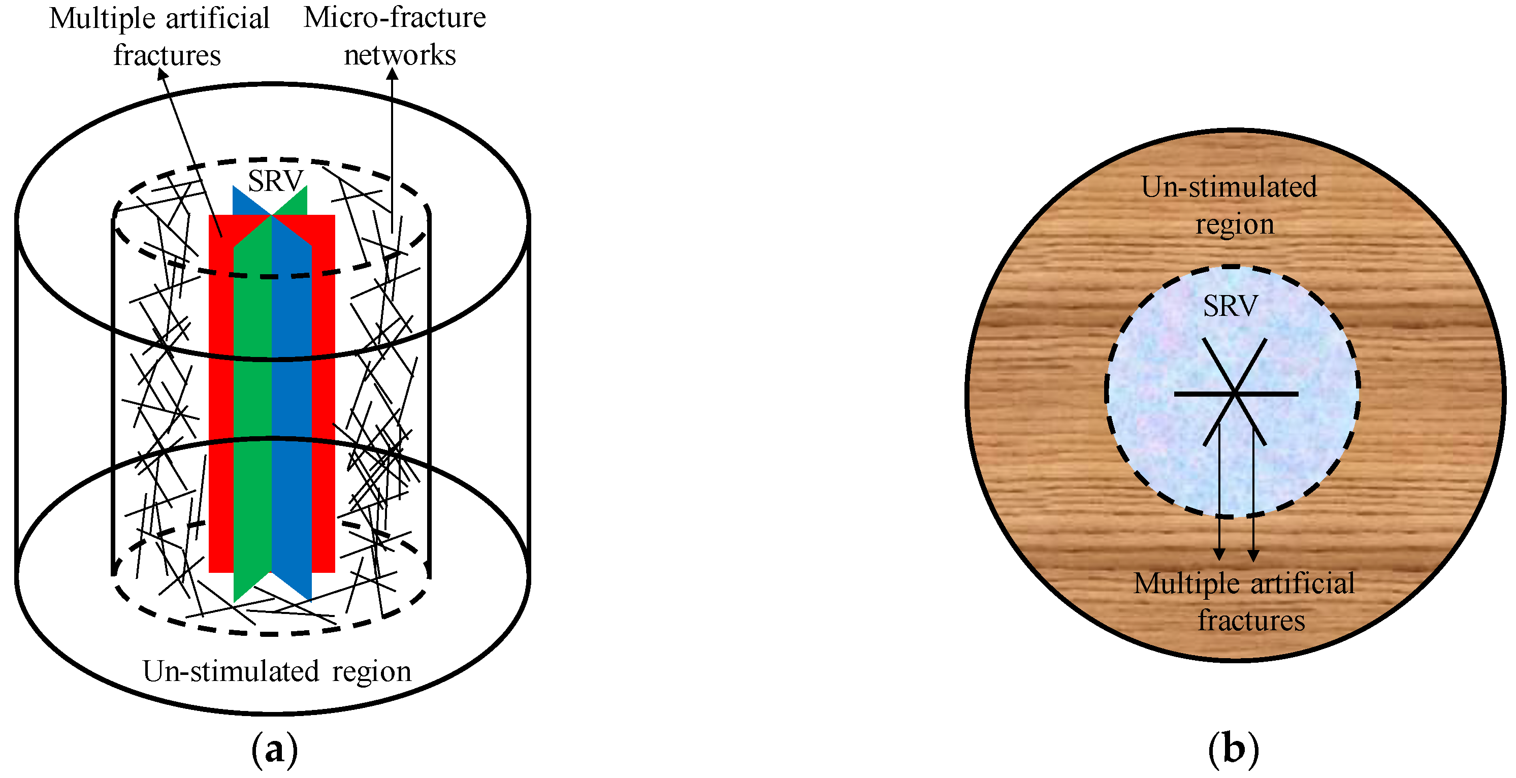
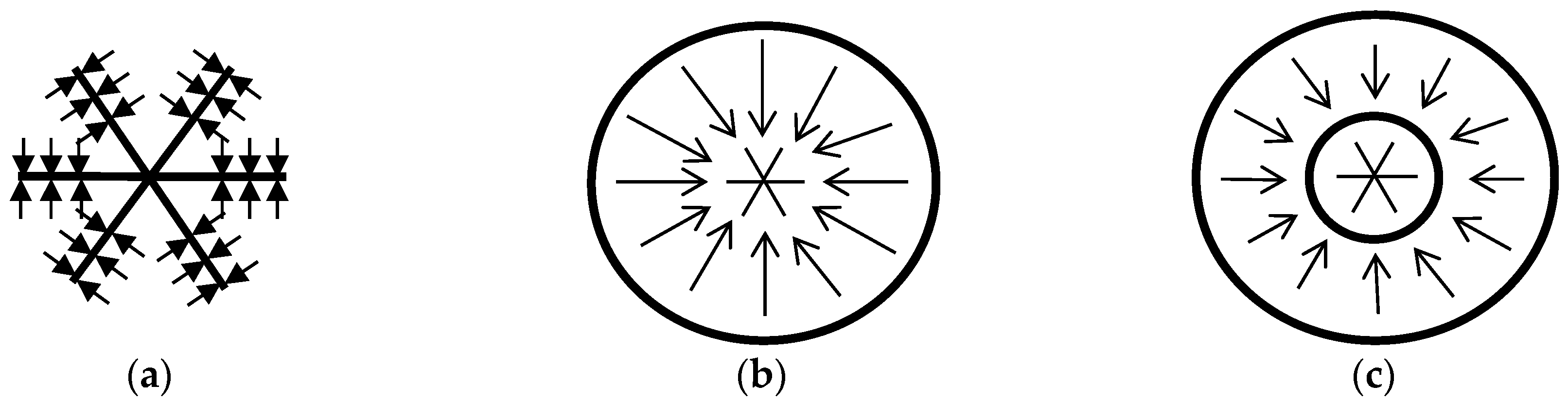
The CBM reservoir can be radially divided into two regions, region 1 and region 2. Region 1, the inner region, includes the micro-fracture network. Whereas region 2 represents the un-stimulated region.
(2)
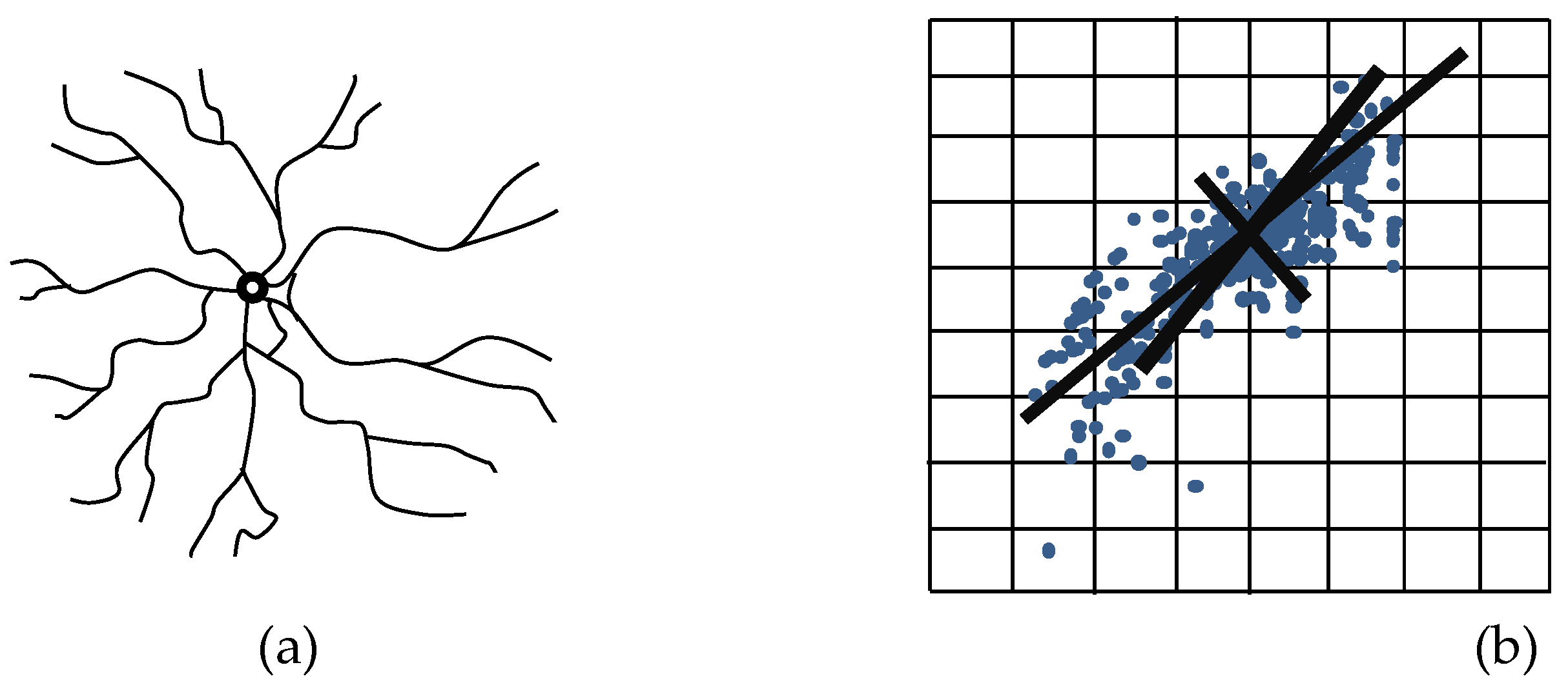
Due to the influences of stimulation treatment, a multiple radial fractures model is adopted to veritably describe the dynamic flow process of CBM.
(3)
Infinite-conductivity artificial fractures are considered.
(4)
The constant production rate of MFVW is defined as qsc, however, the production rates at different locations of a certain fracture are unique.
(5)
The permeability of the micro-fracture network in SRV is considered stress-sensitive.
(6)
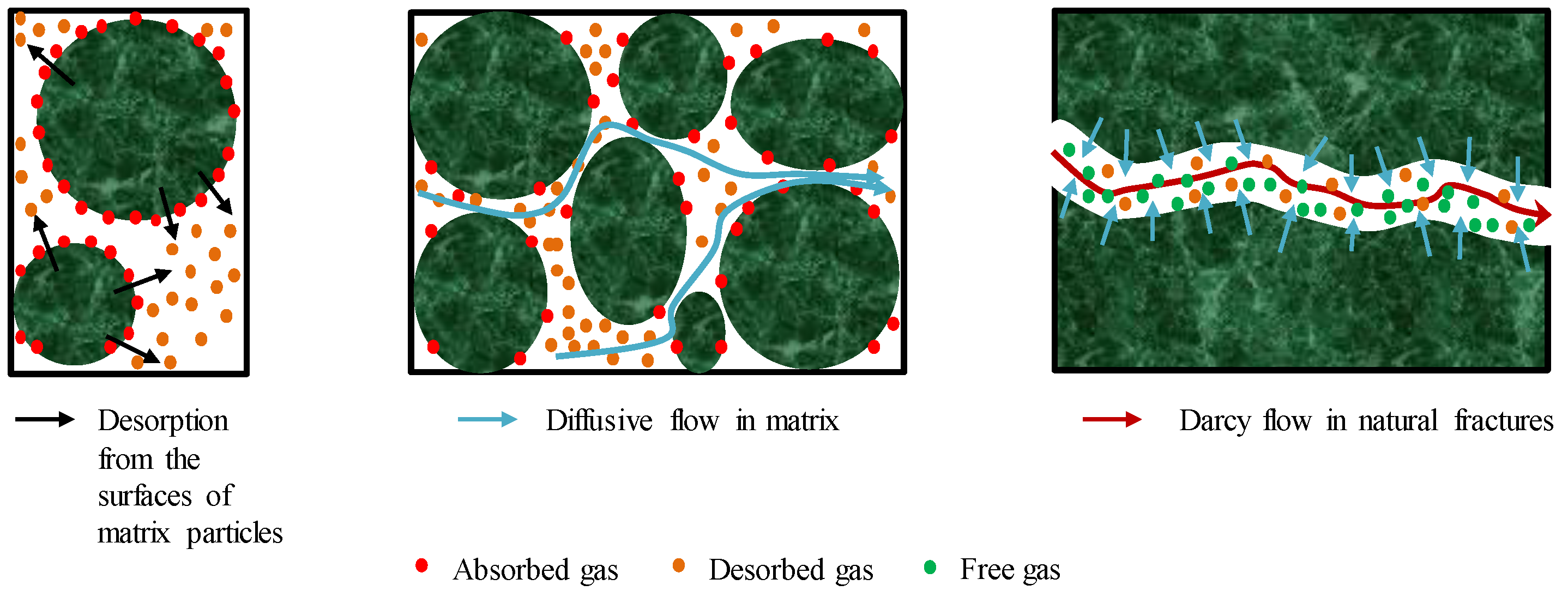
The pseudo-steady state gas diffusion and unsteady state gas diffusion from matrix to fracture network both are considered in this model.
(7)
The outer boundary is infinite and the bottom boundary and top boundary are both impermeable.
(8)
Ignoring capillary pressure and gravity.

3. Mathematical Model

3.1. Continuous Line-Source Solution

In this study, the number of the radial fracture wings is set to M. Each fracture wing is composed of N segments. For each radial fracture wing, the corresponding serial number and angle with respect to X-axis positive direction are defined in a clockwise direction for ease of later programming, as can be seen in Figure 4. As the purpose of this portion is to obtain a continuous line-source solution for a MFVW in a CBM reservoir, the seepage differential equations for two regions should be developed respectively. Then, the continuous line-source function in this composite CBM reservoir can be derived by coupling the governing equation in SRV with that in the un-stimulated region. Zhang et al. [20] proposed a novel line-source function for a CBM reservoir considering Darcy flow and Knudson diffusion. In this study, an improved continuous line-source function for a MFVW in a composite CBM reservoir with consideration of stress sensitivity is presented based on Zhang et al.’s work, see Equation (1). The relevant dimensionless parameter definitions can be found in Appendix A and the derivations of continuous line-source functions under the unsteady state diffusion and pseudo-steady state diffusion in a composite CBM reservoir are shown in Appendix B and Appendix C, respectively.
ξ ¯ 1 fD 0 = q ^ ¯ D [ A c I 0 ( r D ε 1 ) + 1 M 12 K 0 ( r D ε 1 ) ]

3.2. Mathematical Model of MFVW
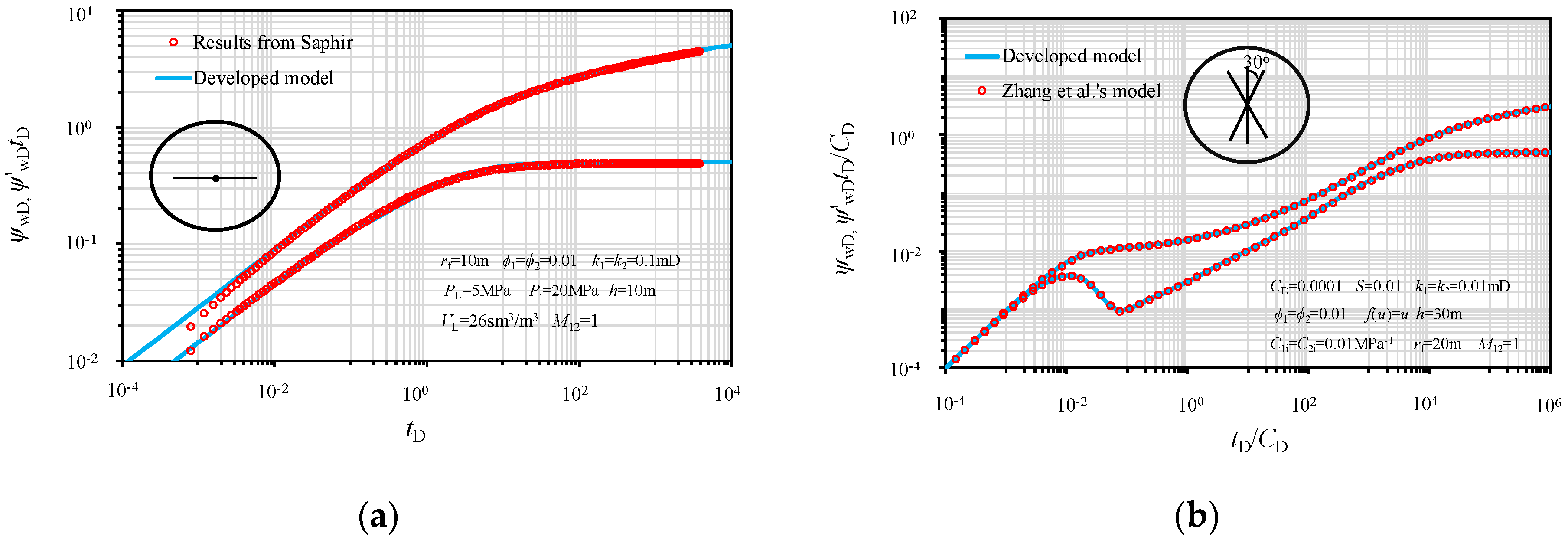
Since it is difficult to obtain the transient pressure response by direct integration of Equation (1), the discretization and superposition methods can be applied in this study. For example, each fracture is composed of N radial small segments and the flux density inside each segment can be considered uniform. Therefore, the transient pseudo pressure response at an arbitrary position in the composite CBM reservoir, generated due to the production of the ith segment of the jth radial fracture, can be obtained by the integration of Equation (1) along the small segment:
ξ ¯ 1 fD 0 ( i , j ) ( x D , y D ) = q ^ ¯ f ( i , j ) q sc Γ G ¯ d l
G ¯ = A c I 0 ( R D ε 1 ) + 1 M 12 K 0 ( R D ε 1 )
R D = ( ( x D x D ( i , j ) ) 2 + ( y D y D ( i , j ) ) 2 )
where q ^ ¯ fD ( i , j ) is the dimensionless flux density of the ith segment of the jth radial fracture and x D ( i , j ) and y D ( i , j ) are the horizontal axis and vertical axis of the middle point of the ith segment of the jth radial fracture, respectively, which can be expressed as follows:
x D ( i , j ) = ( i 1 2 ) Δ r D j cos θ j
y D ( i , j ) = ( i 1 2 ) Δ r D j sin θ j
where θ j is the angle of the jth radial fracture, Δ r D j is the dimensionless radial length of each segment in the jth radial fracture.
Substituting Equations (5) and (6) into Equation (2) results in:
ξ ¯ 1 fD 0 ( i , j ) ( x D , y D ) = q ^ ¯ f ( i , j ) q sc r ¯ ( i , j ) r ¯ ( i + 1 , j ) G ¯ ( R D ) d r = q ^ ¯ f ( i , j ) L ref q sc r ¯ D ( i , j ) r ¯ D ( i + 1 , j ) G ¯ ( R D ) d v
r ¯ D ( i , j ) = ( i 1 ) Δ r D j
where v = r/Lref.
Equation (7) can be rewritten as follows based on the variable substitution method:
ξ ¯ 1 fD 0 ( i , j ) ( x D , y D ) = q ^ ¯ fD ( i , j ) r D ( i , j ) Δ r D j / 2 r D ( i , j ) + Δ r D j / 2 G ¯ ( R D ) d v
R D = ( ( x D v cos θ j ) 2 + ( y D v sin θ j ) 2 )
Because it is time-consuming to directly program Equation (9), variable substitution can be applied again (integration variable v can be displaced by integration variable σ), thus Equation (9) can be further transferred into the following equation:
ξ ¯ 1 fD 0 ( i , j ) ( x D , y D ) = q ^ ¯ fD ( i , j ) Δ r D j / 2 Δ r D j / 2 G ¯ ( R D ) d σ
R D = ( ( x D σ cos θ j r D ( i , j ) cos θ j ) 2 + ( y D σ sin θ j r D ( i , j ) sin θ j ) 2 )
where r D ( i , j ) is the dimensionless radial distance from wellbore to the middle point of the ith segment in the jth radial fracture.
Therefore, the transient pseudo pressure response at the kth segment of the mth radial fracture caused by the ith segment of the jth radial fracture can be provided as:
ξ ¯ 1 fD 0 ( i j , k m ) = q ^ ¯ fD ( i , j ) Δ r D j / 2 Δ r D j / 2 G ¯ ( R D ) d σ
R D = ( ( x D ( k , m ) σ cos θ j r D ( i , j ) cos θ j ) 2 + ( y D ( k , m ) σ sin θ j r D ( i , j ) sin θ j ) 2 )
x D ( k , m ) = ( k 1 2 ) Δ r D m cos θ m
y D ( k , m ) = ( k 1 2 ) Δ r D m sin θ m
Δ r D m = L fD m N
Since the transient pressure response at the kth segment of the mth radial fracture is caused by the production of all the segments (including the kth segment of the mth radial fracture itself), it can be determined by using the following superposition principle:
ξ ¯ MD 0 ( k , m ) = i = 1 N j = 1 M ξ ¯ 1 fD 0 ( i j , k m )
where ξ ¯ 1 fD 0 ( i j , k m ) is the transient pressure response at the kth segment of the mth radial fracture caused by the ith segment of the jth radial fracture.
In addition, due to the infinite-conductivity radial fractures, we can obtain:
ξ ¯ wD = ξ ¯ MD 0 ( 1 , 1 ) = ξ ¯ MD 0 ( 1 , 2 ) = = ξ ¯ MD 0 ( k = N , m = M ) = ξ ¯ MD 0 ( k , m )
According to Equation (19), for M × N segments, we can obtain M × N algebraic equations with ( M × N + 1 ) unknowns, ξ ¯ wD , q ^ ¯ fD ( 1 , 1 ) , q ^ ¯ fD ( 1 , 2 ) , q ^ ¯ fD ( N , M ) . As a result, one more linear algebraic equation is required to obtain the final solution.
i = 1 N j = 1 M q ^ ¯ fD ( i , j ) Δ r D j = 1 u
where Equation (20) represents the total production rate of the well being equal to the summation of the production rates of all M × N segments in the Laplace domain.
Additionally, the Duhamel’s principle can be employed to incorporate both wellbore storage and skin effects. In this study, the expression presented by Kucuk and Ayestaran [31] and Gringarten et al. [32] is applied to consider the influences of the wellbore storage and skin factor:
ξ ¯ wDv = u ξ ¯ wD + S u + C D u 2 ( u ξ ¯ wD + S )
where ξ ¯ wDv is the dimensionless pseudo BHP with consideration of wellbore storage and skin factor in the Laplace domain.
In addition, the BHP response of the well in the time domain can be determined by applying the Stehfest numerical inversion method [33,34,35,36].
ξ wDv ( t D ) = ln 2 t D i = 1 N V i ξ ¯ wDv ( ln 2 t D i )
Finally, the term ξ wDv ( t D ) in Equation (22) is the zero-order perturbation solution for the dimensionless pseudo BHP. Therefore, the real dimensionless pseudo BHP in this study, which takes stress sensitivity in the micro-fracture network into account, can be determined by employing Equation (23) [4,5]:
ψ wD ( t D ) = 1 γ D ln [ 1 γ D ξ wDv ( r D , t D ) ]

4. Model Validation

In order to validate the developed model, two comparisons in terms of pseudo pressure response (PPR) and pseudo pressure derivative (PPD), one between the developed model and commercial software and the other one between the developed model and the model proposed by relevant researchers, are conducted. Because it is hard to consider multi-wing fractured wells in software, the conventional fractured well with two-wing fractures is adopted, where the angles of right and left radial fracture are set to 0° and 180°, respectively. The effect of SRV is ignored, suggesting identical petro-physical properties of the inner region and outer region. In addition, because the model in Saphir considers that the desorbed CBM molecules directly enter the natural fracture network, we utilized f(u) to replace f1(u) and f2(u) in the Laplace domain. Figure 5a shows the satisfactory comparison results, indicating the developed model is reliable.
The second comparison between the developed model and the model proposed by Zhang et al. [20] focuses on the effect of multi-wing fractures on the PPR and PPD. To be more specific, desorption and diffusion of CBM molecules are ignored and the petro-physical properties of the inner and outer region are identical. Based on the results from Figure 5b, the developed model is in good agreement with the proposed model, again, denoting the reliability of the developed model.

5. Results and Discussion

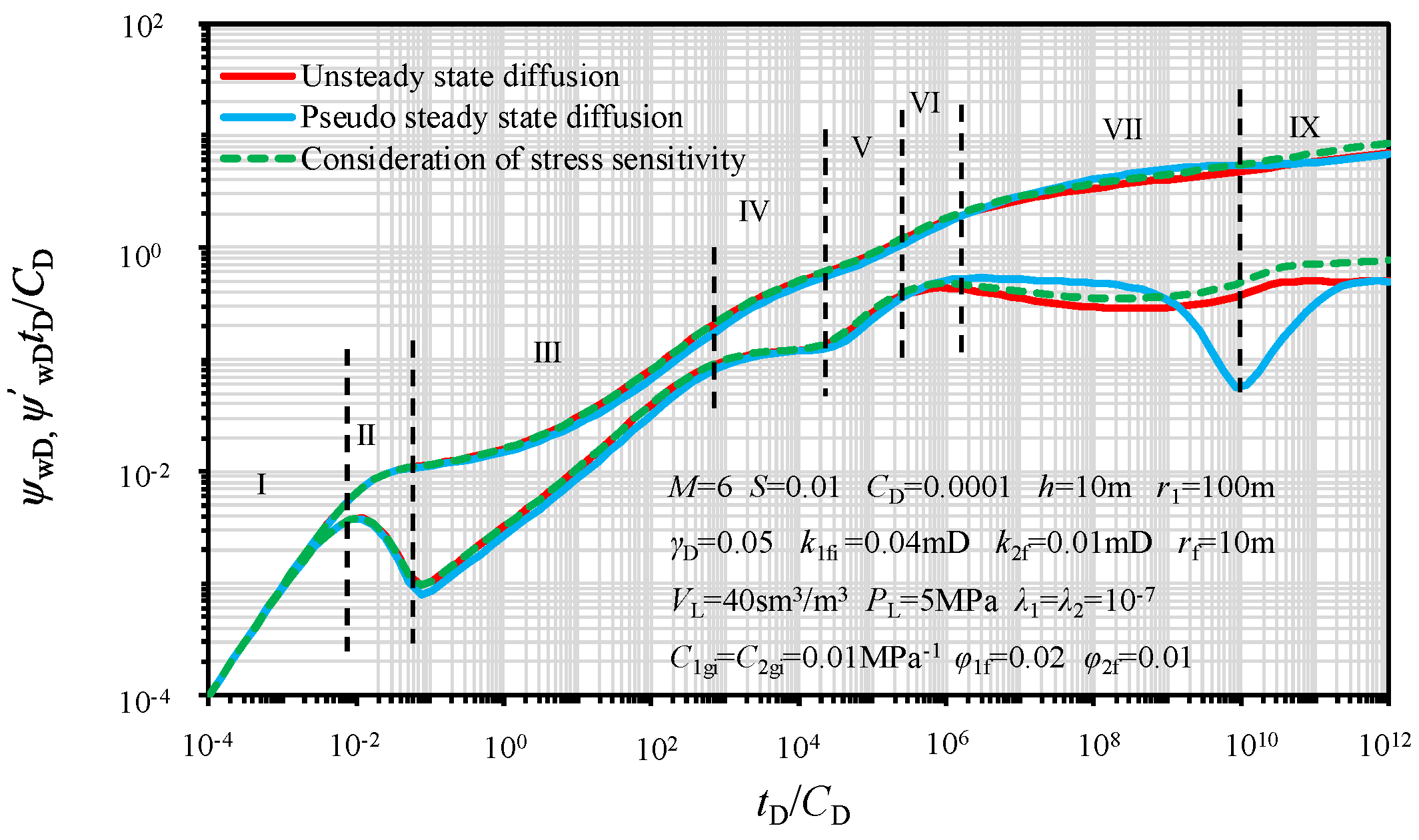
5.1. Type Curves for the Proposed Model

According the description in Section 3, since there are ( M × N + 1 ) algebraic equations with ( M × N + 1 ) unknowns, the combination of Equation (18) to Equation (23) and the utilization of computer programming could result in the time-dependent PPR and PPD, see Figure 6. Based on Figure 6, the type curves resulting from the proposed model can be divided into the following eight flow regimes:
Stage 1: Wellbore storage. The PPR and PPD both are straight lines with unit slope during this flow regime.
Stage 2: Short-time transition flow regime. An obvious hump can be observed in the PPD.
Stage 3: Fracture linear flow regime in SRV. The linear fluid flow from SRV to fractures occurs during this regime and the PPR curves are the straight lines with a slope of 1/2.
Stage 4: Pseudo-radial flow in SRV. As the pressure wave propagates, the pseudo-radial flow in SRV can be observed during this regime and the curve of the PPR exhibits a horizontal line. It is worth noting that this flow regime is subject to the radial fracture length–SRV radius ratio.
Stage 5: Short-time transition flow regime from pseudo-radial flow in the inner region to radial fluid flow in the outer region.
Stage 6: Radial flow regime in the natural fracture system of the outer region. As the pressure wave propagates farther, the SRV-centered radial flow occurs in the outer region. This flow regime is characterized as a flat trend in the PPD curve during this period.
Stage 7: Diffusive flow regime (matrix-dominated flow regime). The gas concentration difference between the natural fracture system and matrix can be expected with the production of CBM residing in the natural fracture system in the outer region, CBM molecules start to desorb from the surfaces of mineral particles in the matrix and diffuse into the natural fracture system under the effect of concentration difference between the natural fracture system and coal seam matrix. For the pseudo-steady state diffusion model, an obvious “dip” appears in the PPD curve during this flow regime, however, for the unsteady state diffusion model, a less obvious “dip” can be found in the PPD curve during this flow regime.
Stage 8: Pseudo-radial flow in the unstimulated regime. A dynamic balance is achieved for the gas transfer between the natural fracture system and the coal seam matrix in the un-stimulated region and the PPD curve exhibits a horizontal line, whose vertical-axis value is 0.5.
It is worth noting that the upward trend both in the PPR and PPD at late flow periods can be observed if the stress-sensitive effect of the fracture network in SRV is considered, representing that more pressure depletion is required for the production of CBM in stress-sensitive reservoirs, see Figure 6.
Additionally, because the un-steady state diffusion model is more practical in most cases, the un-steady state diffusion model is applied here to perform the following PPR/PPD-sensitive analyses. Figure 7 illustrates the three main flow regimes resulting from the proposed model.

5.2. Effect of the Ratio of Permeability in the Inner Region on that in the Outer Region

In the following subsections, sensitivity analyses are performed in terms of several key parameters for the development of CBM based on the developed model and programming. Usually, SRV can be generated after stimulation treatment for the cost-effective development of unconventional hydrocarbon. As a result, the determination of permeability of SRV is of great significance [37]. Figure 8 demonstrates the impacts of the ratio of the permeability in the SRV to that in the un-stimulated region, M12, on the PPR/PPD for a rate-constant production. The PPR/PPD decreases with increasing M12 in both linear and pseudo-radial flow regimes, denoting that the higher permeability of SRV is able to decrease energy consumption for the rate-constant production. Therefore, the initialization of SRV is of great importance for the effective development of CBM.

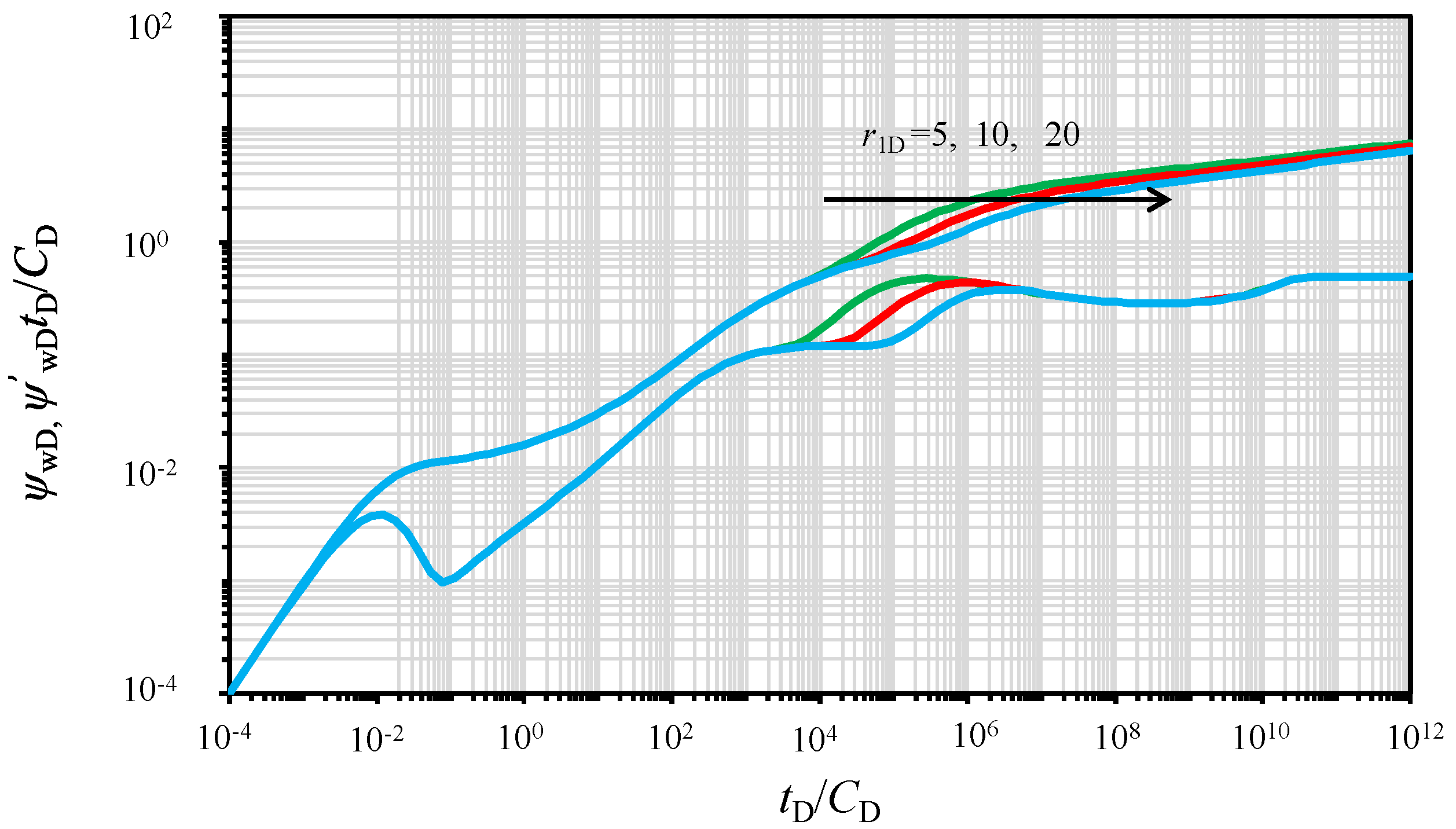
5.3. Effect of the Radius of SRV Region

Figure 9 illustrates the influence of the varied SRV radius (r1) on the PPR/PPD while the rate production keeps constant. The parameter r1D is the dimensionless radius of SRV in the composite CBM reservoirs, including the induced micro-fracture network and multiple fracture wings. As can be seen in Figure 9, the SRV radius dramatically affects the duration time of the pseudo-radial flow in SRV. More specifically, larger dimensionless radius of SRV corresponds to the longer duration time of the pseudo-radial flow regime in SRV, denoting that more pressure (or energy) is required for production.

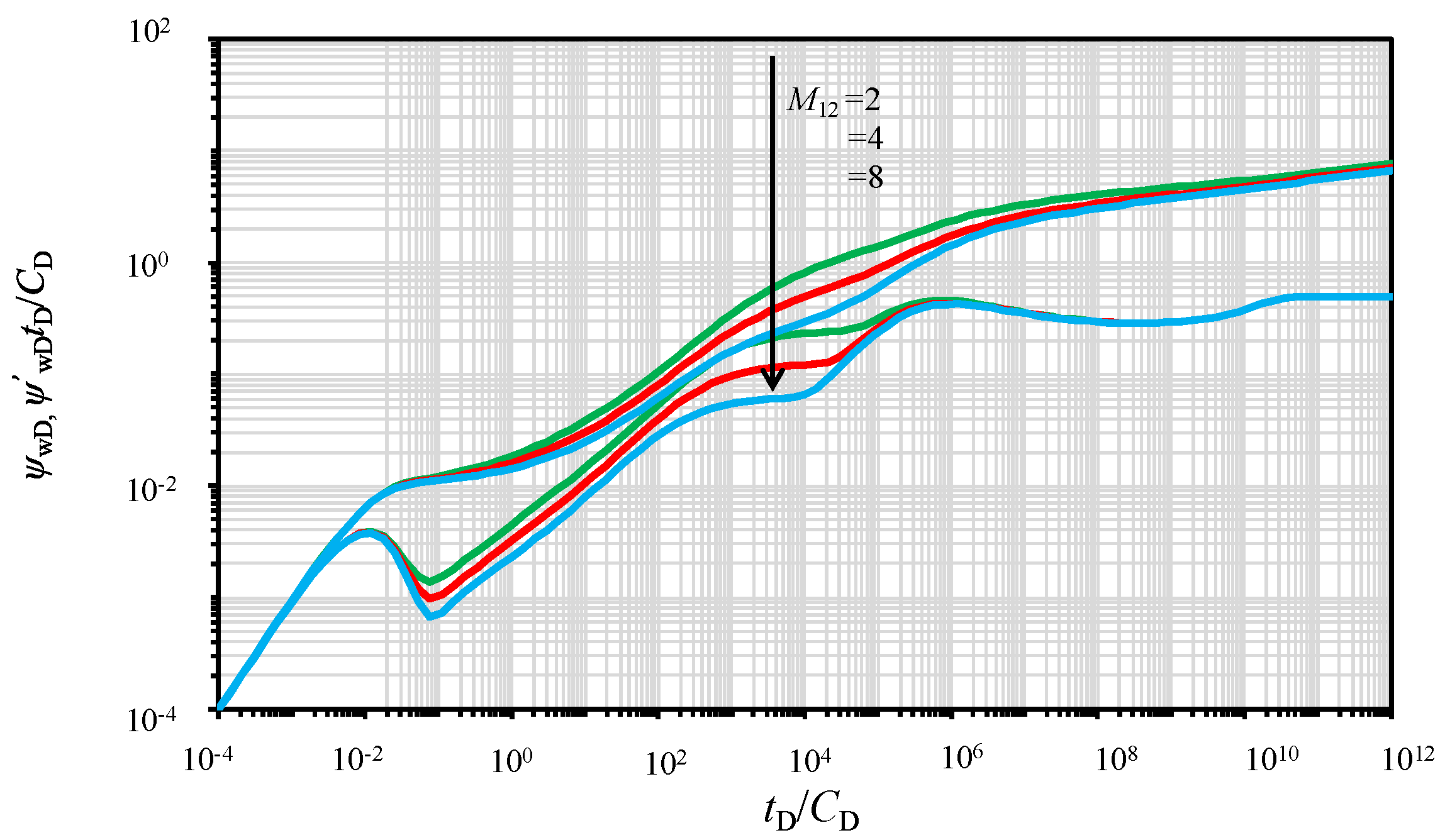
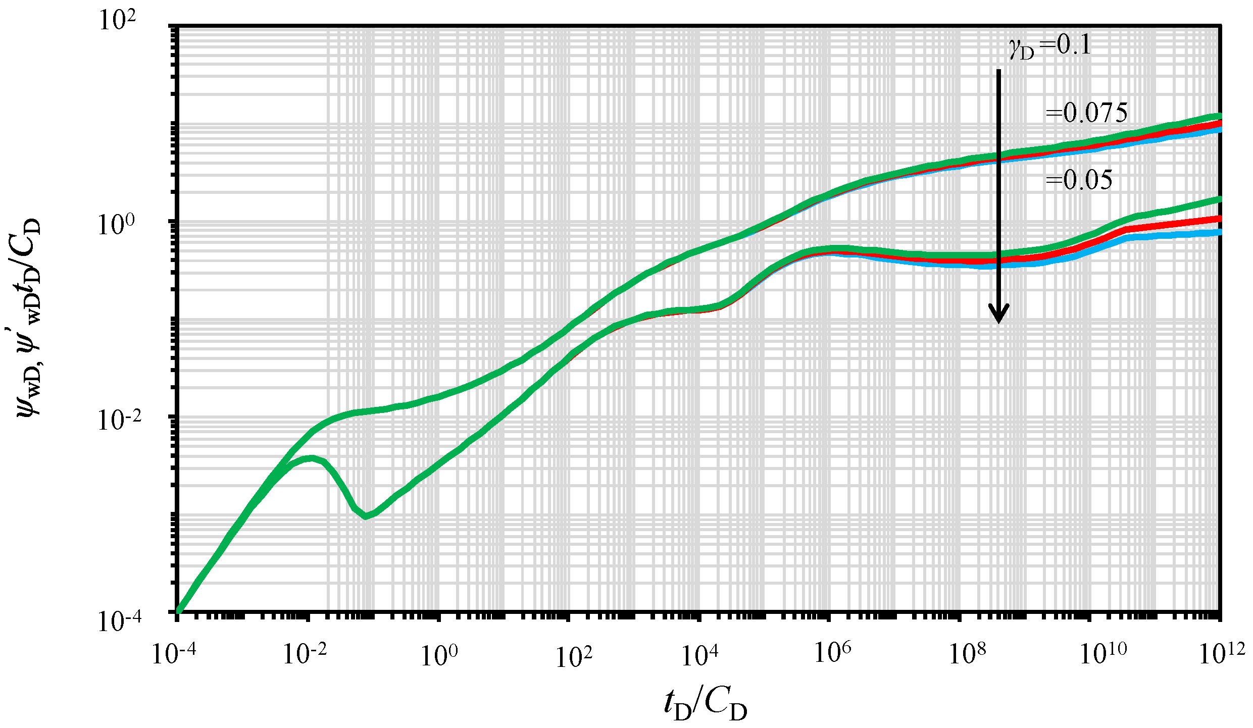
5.4. Effect of Permeability Modulus

Since stress-sensitive permeability of the micro-fracture network in SRV is considered in this study, Figure 10 illustrates the impact of the permeability modulus ( γ D ) on the PPR/PPD for the rate-constant production. Based on Figure 10, a smaller permeability modulus corresponds to the lower PPR/PPD (less obvious upward trend) in late flow regimes, which represents that the existence of stress sensitivity leads to larger pressure depletion in reservoirs compared with the no-stress-sensitivity case.

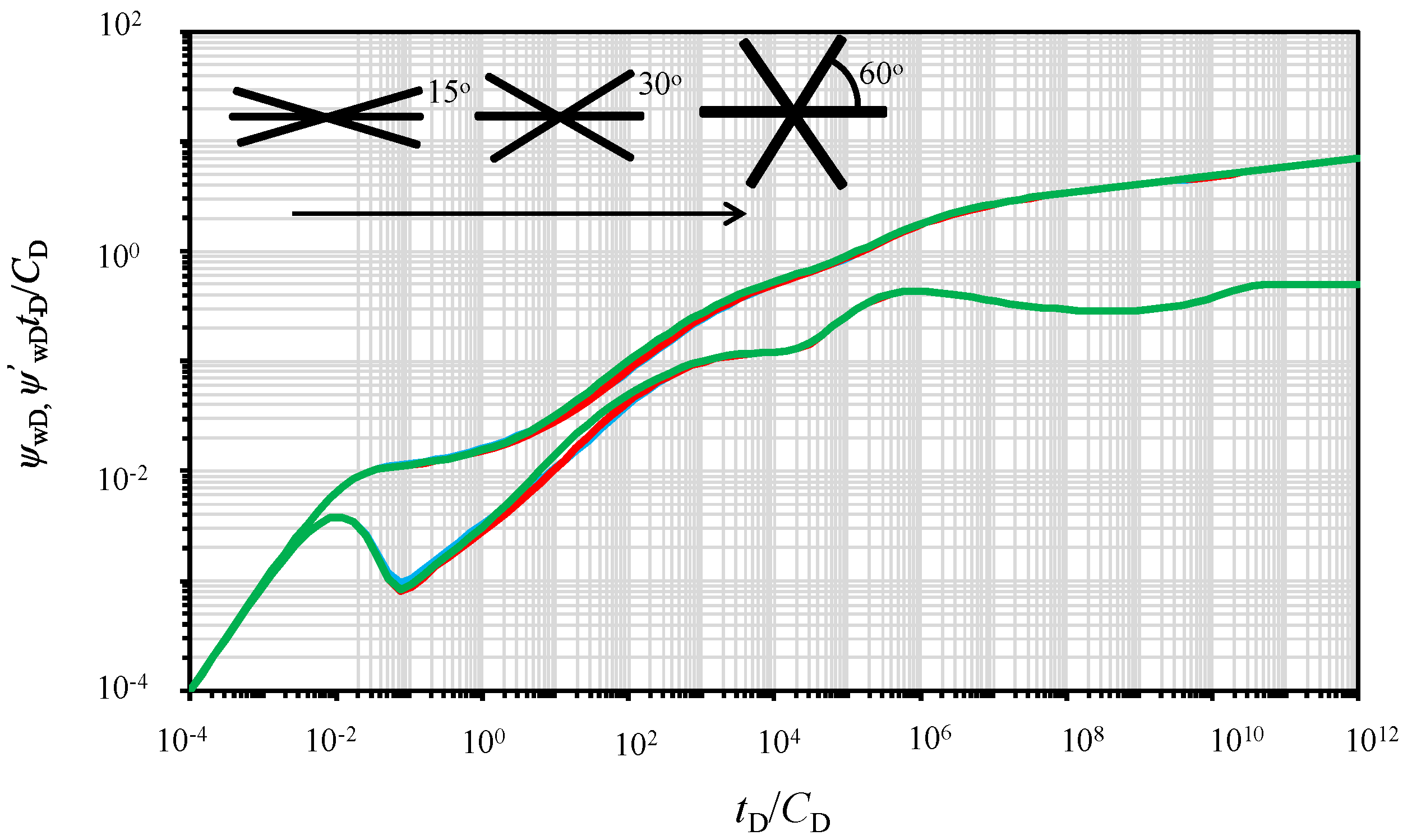
5.5. Effect of Radial Fracture Angle Symmetry

Figure 11 illustrates the impact of radial fracture wing angle symmetry on the PPR/PPD. As shown in Figure 11, the PPR/PPD increases with the increasing θ3 and θ6 and with the decreasing θ1 and θ4 in the later period of linear flow. This can be explained by the fact that the fracture interference becomes more severe as the angle between adjacent radial fractures decreases. That is to say, uniformly distributed radial fracture wings are able to weaken the fracture interference, and, as a result, reduce the energy consumption.

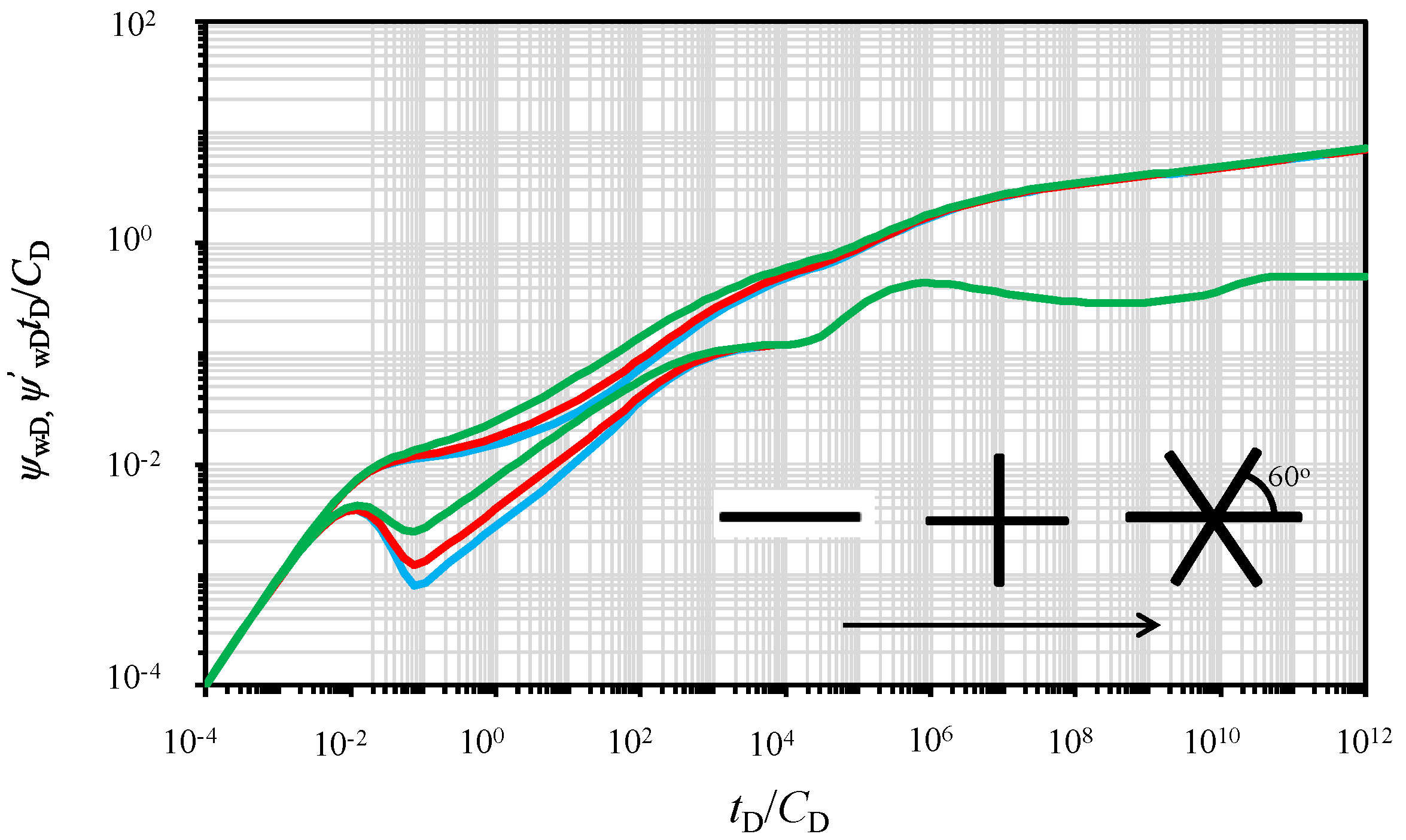
5.6. Effect of the Number of Fracture Wings

Figure 12 presents the effect of the number of radial fracture wings on the PPR/PPD. Based on Figure 12, the number of radial fracture wings impacts the PPR/PPD drastically. The PPR/PPD decreases with the increasing number of radial fracture wings from two to six. Therefore, the generation of multiple radial fracture wings is able to reduce the pressure depletion (energy consumption) required for production. The results obtained here are of great importance for the practical stimulation design.

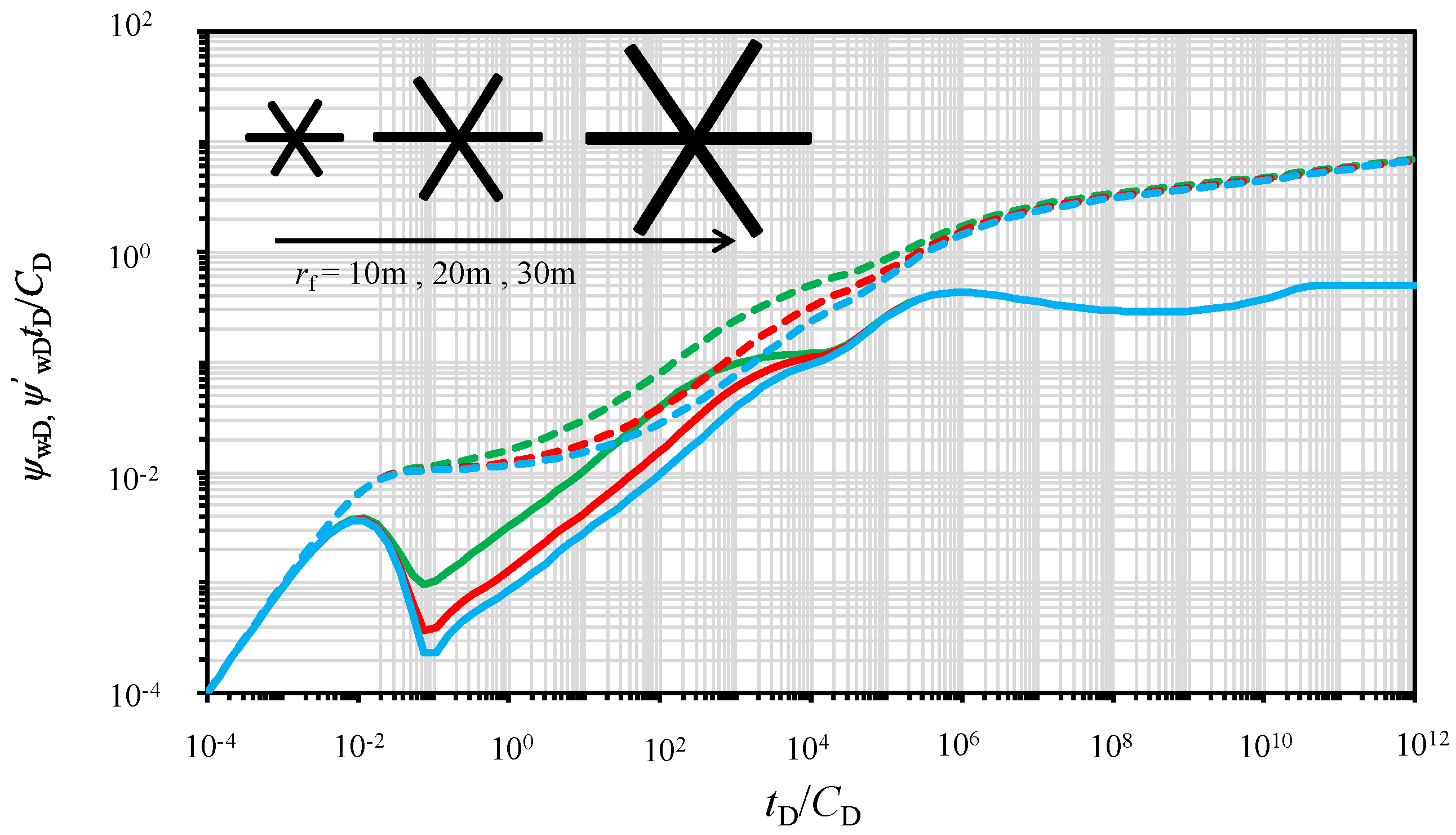
5.7. Effect of the Length of Hydraulic Fracture Wings

Figure 13 illustrates the impact of the length of radial fracture wings on the PPR/PPD for a rate-constant production. The linear flow regime and pseudo-radial flow regime in SRV can be affected by the length of radial fracture wings for a constant SRV radius, see Figure 13. The PPR/PPD decreases with the increasing length of radial fracture wings from 10m to 30m and the duration time of the pseudo-radial flow in SRV becomes shorter as the length of radial fracture wing increases. More specifically, the radial fracture wings with smaller length increase the pressure depletion during production.

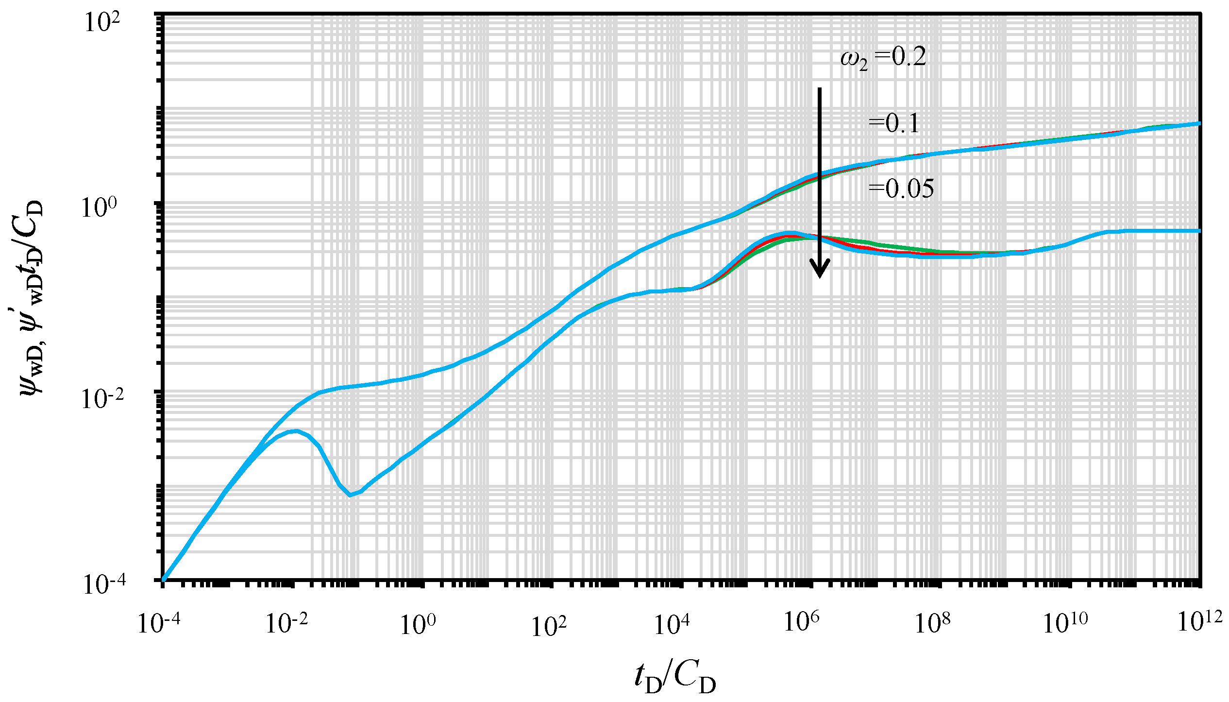
5.8. Effect of the Storativity Ratio of the Outer Region

Since the double-porosity system is considered in this study, Figure 14 shows the effect of the storativity ratio of the outer region on the PPR/PPD. The storativity ratio of the outer region mainly affects the diffusive flow regime in the outer region, see Figure 14. A lower storativity ratio of the outer region corresponds to a wider and deeper concave during this flow regime.

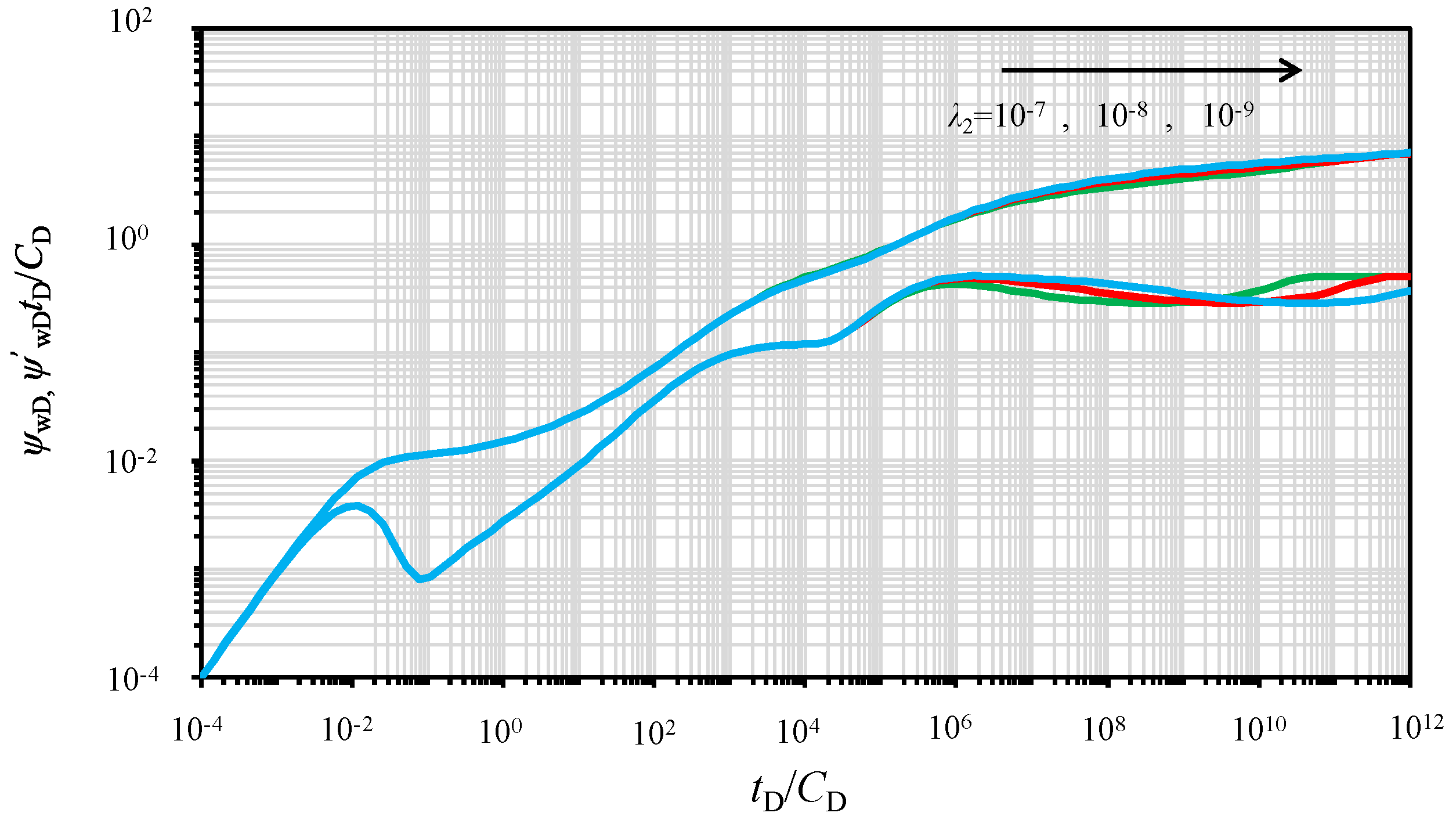
5.9. Effect of the Inter-Porosity Flow Parameter

The other important parameter resulting from the double-porosity system is the inter-porosity flow parameter. Figure 15 demonstrates the effect of the inter-porosity flow parameter on the PPR/PPD for the rate-constant production. Based on the results provided by Figure 15, the inter-porosity flow parameter affects the diffusion flow regime drastically: the diffusion flow regime occurs later as the inter-porosity flow parameter decreases.

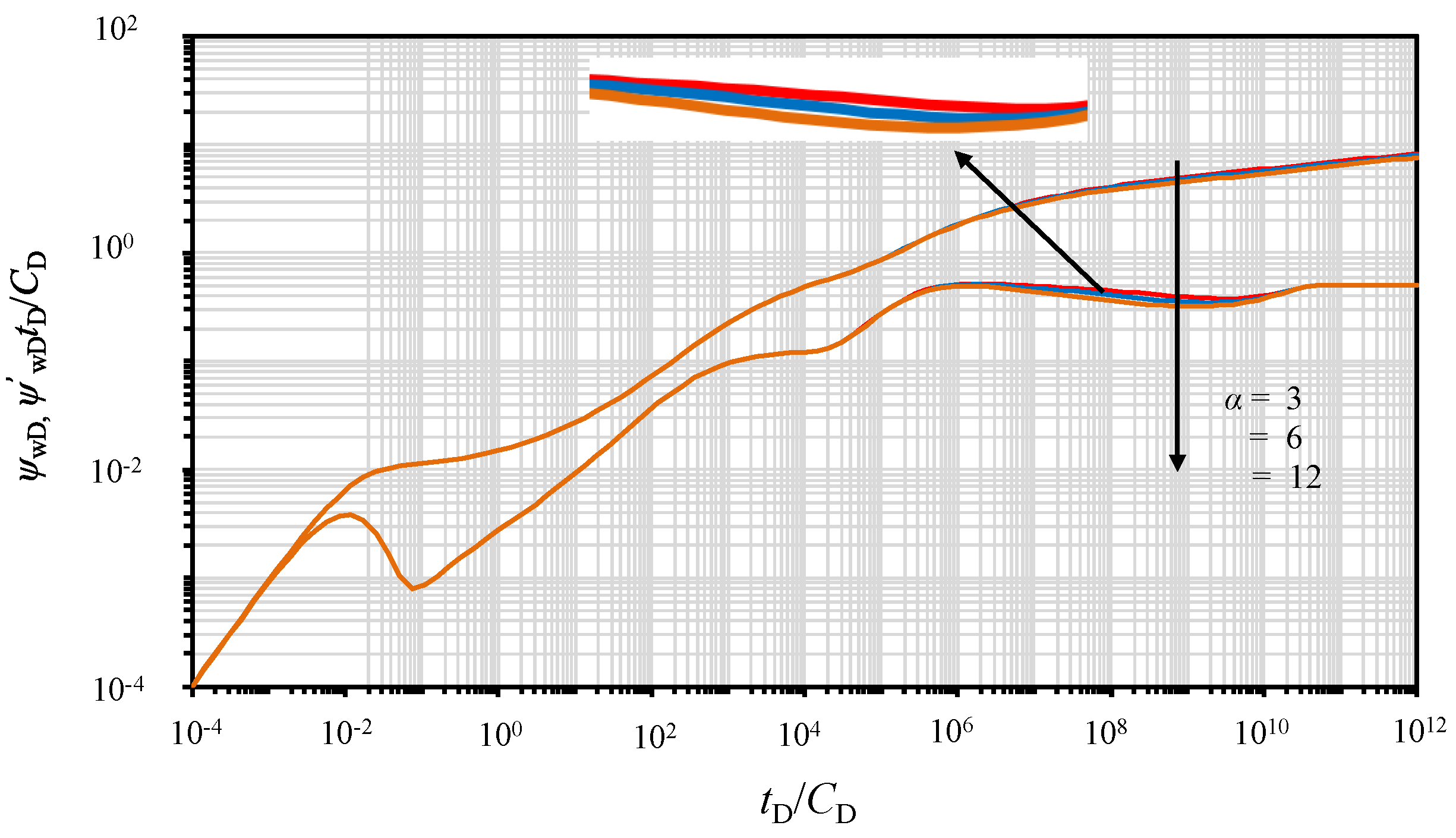
5.10. Effect of the Adsorption–Desorption Constant

Figure 16 shows the effect of the adsorption–desorption constant on the PPR/PPD. The adsorption–desorption constant mainly affects the diffusion flow regime, as can be seen in Figure 16. More specifically, a higher adsorption–desorption constant corresponds to a deeper and wider concave, which represents the diffusion regime. The adsorption–desorption constant is adopted in this study to represent the amount of gas adsorbed at the surface of mineral surfaces and a higher adsorption–desorption constant denotes more adsorbed gas existing in the coal seam matrix. Therefore, more adsorbed gas is able to desorb and diffuse into the fractures for a larger adsorption–desorption constant during production.

6. Conclusions

This work presents a semi-analytical model for a vertical well with multiple radial fracture wings in a stress-sensitive CBM reservoir. The corresponding PPR and PPD in the well bottom are determined and discussed. The conclusions obtained in this work are shown as follows:
(1)
The linear flow between adjacent radial fracture wings, the radial flow in the SRV, and the radial flow in the outer region are the three main flow regimes for the proposed model in CBM reservoirs.
(2)
The impact of stress sensitivity on the PPR/PPD is obvious. The existence of stress sensitivity in the micro-fracture network results in larger pressure depletion in later flow regimes.
(3)
The SRV, which includes the micro-fracture network and radial fracture wings, is able to reduce the pressure depletion. As the size of the SRV becomes smaller, the transition flow regime from pseudo-radial flow in the SRV to radial flow in the outer region occurs earlier.
(4)
The properties and distribution of multiple radial fracture wings affect the PPR/PPD in CBM reservoirs drastically. An increase in the number of radial fracture wings leads to a decrease in the pressure depletion when producing. The well model with an un-uniform fracture wing distribution requires more energy consumption compared to that with a uniform fracture wing distribution when producing at the same rate.
(5)
The storativity ratio and the inter-porosity flow parameter of the outer region, two parameters in a double-porosity system, mainly affect the diffusion flow regime, where the storativity ratio of the outer region represents the capacity of gas supply for the matrix and the inter-porosity flow parameter denotes the diffusion occurrence time. In addition, the adsorption–desorption constant characterizes the amount of adsorbed gas in the matrix.

Author Contributions

Z.K. designed the research and built the model; H.W. made sensitivity analyses and was in charge of writing. All authors have read and agree to the published version of the manuscript.

Funding

The authors are gratefully appreciative of the financial support from the National Natural Science Foundation of China (Grant No. 51774243, 51534006) and the National Science and Technology Major Project of China during the 13th Five-Year Plan Period (Grant No. 2016ZX05062).

Acknowledgments

The authors would also like to thank the reviewers and editors whose critical comments were very helpful in preparing this article.

Conflicts of Interest

The authors declare no conflict of interest.

Nomenclature

Cwellbore storage coefficient: m3/Pa
Cggas compressibility, Pa−1
hformation thickness, m
kpermeability, m2
Lreference length, m
Lflength of hydraulic fracture, m
Mnumber of hydraulic fracture wings
Ppressure, Pa
qproduction rate, m3/s
q ^ strength of continuous line source, m3/s
rradial distance, m
r1radius of inner region, m
Sskin factor
ttimes, s
Ttemperature, K
uLaplace transform variable
x,yspatial coordinates, m
ZZ-factor
Vgas concentration in matrix
λ inter-porosity flow coefficient
ω storativity ratio
μ viscosity, Pa·s
ϕ porosity
ψ pseudo pressure, 2 p 0 p p μ Z d p , Pa/s

Superscripts

variables in the Laplace domain

Subscripts

Ddimensionless
fnatural fracture
mmatrix
1SRV region
2un-stimulated region
1mmatrix system in the SRV region
2mmatrix system in the un-stimulated region
1fnatural fracture system in the SRV region
2finatural fracture system in the un-stimulated region at initial condition
gigas at initial condition
iinitial condition
scstandard condition
wwellbore

Appendix A. Dimensionless Variables Definition

Dimensionless variables are defined based on the parameters in the un-stimulated region. The non-dimensional radius, non-dimensional pseudo pressure, and non-dimensional time can be defined as follows, respectively:
r D = r L ref
ψ ξ fD = π k 2 fi h q sc T sc T p sc ( ψ i ψ ξ f ) | ξ = 1 , 2
t D = k 2 fi t Λ L ref 2
where Lref is reference length, which can be replaced by the length of radial fracture, rf, in this study.
Some dimensionless parameters regarding the dual-porosity system are defined as follows:
ω ξ = ( ϕ f μ gi C gi ) ξ Λ | ξ = 1 , 2
Λ = ϕ f μ gi C gi + 6 π k fi h q sc   for   unsteady   state   diffusion
Λ = ϕ f μ gi C gi + 2 π k fi h q sc   for   pseudo - steady   state   diffusion
λ = D Λ k fi L ref 2 R 2   for   unsteady   state   diffusion
λ = 6 π 2 D Λ k fi L ref 2 R 2   for   pseudo - steady   state   diffusion
The dimensionless gas concentration difference in matrix can be defined as:
V ξ D = V ξ - V i | ζ = 1 , 2
The ratio of the permeability in SRV to that in un-stimulated region is given as follows:
M 12 = k 1 fi k 2 f
The dimensionless wellbore storage coefficient is defined as:
C D = C 2 π h Λ L ref 2 / μ gi
In addition, the following dimensionless variables can be obtained:
t D C D = 2 π h k 2 fi t C μ gi

Appendix B. Continuous Line-Source Function under Pseudo-Steady State Diffusion in Composite CBM Reservoir

Based on the dimensionless parameters in Appendix A and the models adopted by Wang et al. [3], the governing equations of the micro-fracture network and matrix in the SRV in the Laplace domain are given as, respectively:
d 2 ξ ¯ 1 fD 0 d r D 2 + 1 r D d ξ ¯ 1 fD 0 d r D = ω 1 M 12 u ξ ¯ 1 fD 0 ( 1 ω 1 ω 2 ) u M 12 V ¯ 1 D
V ¯ 1 D = α 1 λ 1 u + λ 1 ψ ¯ 1 fD
It is worth noting that the term ξ ¯ 1 fD 0 in Equation (A13) is the zero-order perturbation solution for the dimensionless pseudo pressure of the micro-fracture network in the inner region.
Associated with the perturbation technology, substituting Equation (A14) into Equation (A13) leads to:
d 2 ξ ¯ 1 fD 0 d r 2 D + 1 r D d ξ ¯ 1 fD 0 d r D = f 1 ( u ) ξ ¯ 1 fD 0
where
f 1 ( u ) = ω 1 u M 12 + α 1 λ 1 u ( 1 ω 1 ω 2 ) M 12 ( u + λ 1 )
Next, the governing equation of fracture network in the outer region in the Laplace domain can be expressed by:
d 2 ξ ¯ 2 fD 0 d r D 2 + 1 r D d ξ ¯ 2 fD 0 d r D = f 2 ( u ) ξ ¯ 2 fD 0
where
f 2 ( u ) = ω 2 u + α 2 λ 2 u ( 1 ω 1 ω 2 ) ( u + λ 2 )
Subsequently, the general solutions for Equation (A15) and Equation (A17) are, respectively:
ξ ¯ 1 fD 0 = A 1 I 0 ( r D f 1 ( u ) ) + B 1 K 0 ( r D f 1 ( u ) )
ξ ¯ 2 fD 0 = A 2 I 0 ( r D f 2 ( u ) ) + B 2 K 0 ( r D f 2 ( u ) )
By means of perturbation technology, the boundary conditions of Equations. (A19) and (A20) in the Laplace domain are, respectively:
lim ζ D 0 ( r D d ξ ¯ 1 fD 0 d r D ) r D = ζ D = 1 M 12 q ^ ¯ D
ξ ¯ 1 fD 0 | r D = r 1 D = ξ ¯ 2 fD 0 | r D = r 1 D
d ξ ¯ 1 fD 0 d r D | r D = r 1 D = 1 M 12 d ξ ¯ 2 fD 0 d r D | r D = r 1 D
ξ ¯ 2 fD 0 | r D = 0
The combination of Equation (A19) through Equation (A24) results in:
ξ ¯ 1 fD 0 = q ^ ¯ D [ A c I 0 ( r D ε 1 ) + 1 M 12 K 0 ( r D ε 1 ) ]
where
A c = ε 1 K 0 ( r 1 D ε 2 ) K 1 ( r 1 D ε 1 ) 1 M 12 ε 2 K 0 ( r 1 D ε 1 ) K 1 ( r 1 D ε 2 ) M 12 ε 1 I 1 ( r 1 D ε 1 ) K 0 ( r 1 D ε 2 ) + ε 2 I 0 ( r 1 D ε 1 ) K 1 ( r 1 D ε 2 )
ε 1 = f 1 ( u )
ε 2 = f 2 ( u )
r D = ( x D x wD ) 2 + ( y D y wD ) 2

Appendix C. Continuous Line-Source Function under Unsteady State Diffusion in Composite CBM Reservoir

In this subsection, we consider transient diffusive flow model in the matrix. The governing equations of the micro-fracture network and matrix in the SRV in the Laplace domain are given as, respectively:
2 ξ 1 fD 0 r D 2 + 1 r D ξ 1 fD 0 r D = ω 1 M 12 ξ 1 fD 0 t D 1 ω 1 ω 2 M 12 λ 1 V 1 D r 1 mD | r 1 mD = 1
V ¯ 1 D = α 1 sh ( u λ 1 r 1 mD ) sh ( u λ 1 ) r 1 mD ψ ¯ 1 fD
where r1mD is the dimensionless radius of the matrix particle in the inner region and α is defined as the adsorption–desorption constant, which can be given as:
α = V L p L ( p L + p f ) ( p L + p i ) q sc T p sc π k fi h T sc μ i Z i 2 p i
It is worth noting that, since the purpose of the study is to derive the continuous line-source function in the composite CBM reservoirs, α in Equation (A32) can be considered a constant at initial condition.
Therefore, the governing equation of the micro-fracture network in the inner region in the Laplace domain can be rewritten as:
d 2 ξ ¯ 1 fD 0 d r D 2 + 1 r D d ξ ¯ 1 fD 0 d r D = f 1 ( u ) ξ ¯ 1 fD 0
where
f 1 ( u ) = ω 1 M 12 u + 1 ω 1 ω 2 M 12 λ 1 α 1 [ u λ 1 coth ( u λ 1 ) 1 ]
In addition, the governing equation of the fracture network in the outer region in the Laplace domain can be expressed as:
d 2 ξ ¯ 2 fD 0 d r D 2 + 1 r D d ξ ¯ 2 fD 0 d r D = f 2 ( u ) ξ ¯ 2 fD 0
where
f 2 ( u ) = ω 2 u + ( 1 ω 1 ω 2 ) λ 2 α 2 [ u λ 2 coth ( u λ 2 ) 1 ]
Associated with corresponding boundary conditions, the continuous line-source function under the unsteady state diffusion can be determined as follows:
ξ ¯ 1 fD 0 = q ^ ¯ D [ A c I 0 ( r D ε 1 ) + 1 M 12 K 0 ( r D ε 1 ) ]
where
A c = ε 1 K 0 ( r 1 D ε 2 ) K 1 ( r 1 D ε 1 ) 1 M 12 ε 2 K 0 ( r 1 D ε 1 ) K 1 ( r 1 D ε 2 ) M 12 ε 1 I 1 ( r 1 D ε 1 ) K 0 ( r 1 D ε 2 ) + ε 2 I 0 ( r 1 D ε 1 ) K 1 ( r 1 D ε 2 )
ε 1 = f 1 ( u )
ε 2 = f 2 ( u )
r D = ( x D x wD ) 2 + ( y D y wD ) 2

References

  1. Warren, J.E.; Root, P.J. The behavior of naturally fractured reservoirs. SPE J. 1953, 3. [Google Scholar] [CrossRef] [Green Version]
  2. Kou, Z.; Dejam, M. Dispersion due to combined pressure-driven and electro-osmotic flows in a channel surrounded by a permeable porous medium. Phys. Fluids 2019, 31, 056603. [Google Scholar] [CrossRef]
  3. Wang, H. Performance of multiple fractured horizontal wells in shale gas reservoirs with consideration of multiple mechanisms. J. Hydrol. 2014, 510, 299–312. [Google Scholar] [CrossRef]
  4. Guo, J.; Wang, H.; Zhang, L. Transient pressure behavior for a horizontal well with multiple finite-conductivity fractures in tight reservoirs. J. Geophys. Eng. 2016, 12, 638–656. [Google Scholar] [CrossRef]
  5. Wang, H.; Guo, J.; Zhang, L. A semi-analytical model for multilateral horizontal wells in low-permeability naturally fractured reservoirs. J. Pet. Sci. Eng. 2017, 20, 564–578. [Google Scholar] [CrossRef]
  6. Shovkun, I.; Espinoza, D.N. Coupled fluid flow-geomechanics simulation in stress-sensitive coal and shale reservoirs: Impact of desorption-induced stresses, shear failure, and fines migration. Fuel 2017, 195, 260–272. [Google Scholar] [CrossRef]
  7. Pedrosa, O.A., Jr. Pressure transient response in stress-sensitive formations. In Proceedings of the SPE California Regional Meeting, Oakland, CA, USA, 2–4 April 1986. SPE 15115. [Google Scholar]
  8. Zhang, M.; Ambastha, A. New insights in pressure-transient analysis for stress-sensitive reservoirs. In Proceedings of the SPE annual technical conference and exhibition, New Orleans, LA, USA, 25–28 September 1994. [Google Scholar]
  9. Chen, Z.; Liao, X.; Zhao, X.; Dou, X.; Zhu, L. A Semi-Analytical Mathematical Model for Transient Pressure Behavior of Multiple Fractured Vertical Well in Coal Reservoirs Incorporating with Diffusion, Adsorption, and Stress-Sensitivity. J. Nat. Gas Sci. Eng. 2015, 29, 570–582. [Google Scholar] [CrossRef]
  10. Wei, M.; Duan, Y.; Dong, M.; Fang, Q.; Dejam, M. Transient production decline behavior analysis for a multi-fractured horizontal well with discrete fracture network in shale gas reservoirs. J. Porous Media 2019, 22, 343–361. [Google Scholar] [CrossRef]
  11. Wei, M.; Duan, Y.; Dong, M.; Fang, Q. Blasingame decline type curves with material balance pseudo-time modified for multi-fractured horizontal wells in shale gas reservoirs. J. Nat. Gas Sci. Eng. 2016, 31, 340–350. [Google Scholar] [CrossRef]
  12. Yuan, Y.; Yan, W.; Chen, F.; Li, J.; Xiao, Q.; Huang, X. Numerical simulation for shale gas flow in complex fracture system of fractured horizontal well. Int. J. Nonlinear Sci. Num. Simul. 2018, 19, 367–377. [Google Scholar] [CrossRef]
  13. King, G.R.; Ertekin, T.; Schwerer, F.C. Numerical Simulation of the Transient Behaviour of Coal-Seam Degasification Wells. SPE Form. Eval. 1986, 1, 165–183. [Google Scholar] [CrossRef]
  14. Anbarci, K.; Ertekin, T. A Comprehensive Study of Pressure Transient Analysis with Sorption Phenomena for Single-Phase Gas Flow in Coal Seams. In Proceedings of the SPE Annual Technical Conference and Exhibition, New Orleans, LA, USA, 23–26 September 1990. [Google Scholar]
  15. Anbarci, K.; Ertekin, T. Pressure Transient Behavior of Fractured Wells in Coalbed Reservoirs. In Proceedings of the SPE Annual Technical Conference and Exhibition, Washington, DC, USA, 4–7 October 1992. [Google Scholar]
  16. Engler, T.W.; Rajtar, J.M. Pressure Transient Testing of Horizontal Wells in Coalbed Reservoirs. In Proceedings of the SPE Rocky Mountain Regional Meeting, Casper, WY, USA, 18–21 May 1992. [Google Scholar]
  17. Clarkson, C.R.; Jordan, C.L.; Ilk, D.; Blasingame, T.A. Production Data Analysis of Fractured and Horizontal CBM Wells. In Proceedings of the SPE Eastern Regional Meeting, Charleston, WV, USA, 23–25 September 2009. [Google Scholar]
  18. Nie, R.; Meng, Y.; Guo, J.; Jia, Y. Modeling transient flow behavior of a horizontal well in a coal seam. Int. J. Coal. Geo. 2012, 92, 54–68. [Google Scholar] [CrossRef]
  19. Zhao, Y.; Zhang, L.; Feng, G.; Zhang, B.; Kang, B. Performance Analysis of Fractured Wells with Stimulated Reservoir Volume in Coal Seam Gas Reservoirs. Oil Gas Sci. Technol. 2016, 71, 8. [Google Scholar] [CrossRef] [Green Version]
  20. Zhang, L.; Kou, Z.; Wang, H.; Zhao, Y.; Dejam, M.; Guo, J.; Du, J. Performance Analysis for A Model of A Multi-Wing Hydraulically Fractured Vertical Well in A Coalbed Methane Gas Reservoir. J. Pet. Sci. Eng. 2018, 166, 104–120. [Google Scholar] [CrossRef]
  21. Kou, Z.H.; Dejam, M. A mathematical model for a hydraulically fractured well in a coal seam reservoir by considering desorption, viscous flow, and diffusion. Proceedings of 71st Annual Meeting of the APS Division of Fluid Dynamics, Atlanta, GA, USA., 18–20 November 2018. [Google Scholar]
  22. Luo, W.J.; Tang, C.F. Pressure-transient analysis of multi-wing fractures connected to a vertical wellbore. SPE J. 2014, 20, 360–367. [Google Scholar] [CrossRef]
  23. Germanovich, L.N.; Ring, L.M.; Astakhov, D.K.; Shlyapobersky, J.; Mayerhofer, M.J. Hydraulic Fracture with Multiple Segments II. Modeling. Int. J. Rock Mech. Min. Sci. 1997, 34, e1–e15. [Google Scholar] [CrossRef]
  24. Craig, D.P.; Blasingame, T.A. Constant-Rate Drawdown Solutions Derived for Multiple Arbitrarily Oriented Uniform-Flux, Infinite-Conductivity, or Finite-Conductivity Fractures in an Infinite-slab Reservoir. In Proceedings of the SPE Gas Technology Symposium, Calgary, AB, Canada, 15–17 May 2006. [Google Scholar]
  25. Choo, Y.K.; Wu, C.H. Transient Pressure Behavior of Multiple-Fractured Gas Wells. In Proceedings of the SPE/DOE Low Permeability Reservoirs Symposium, Denver, CO, USA, 18–19 May 1987. [Google Scholar]
  26. Tiab, D. Analysis of Pressure Derivative Data of Hydraulically Fractured Wells by the Tiab’s Direct Synthesis Technique. J. Pet. Sci. Eng. 2005, 49, 1–21. [Google Scholar] [CrossRef]
  27. Hou, X.; Zhang, X.; Guo, B. Mathematical Modeling of Fluid Flow to Unconventional Oil Wells with Radial Fractures and Its Testing with Field Data. ASME J. Energy Resour. Technol. 2019, 141, 070702. [Google Scholar] [CrossRef]
  28. He, L.; Mei, H.Y.; Hu, X.R.; Dejam, M.; Kou, Z.H.; Zhang, M.L. Advanced flowing material balance to determine original gas-in-place of shale gas considering adsorption hysteresis. SPE Reser. Eval. Eng. 2019, 22, 1282–1292. [Google Scholar] [CrossRef]
  29. Chen, Z.M.; Liao, X.W.; Zhao, X.L.; Dou, X.J.; Zhu, L.T. Performance of horizontal wells with fracture networks in shale gas formation. J. Pet. Sci. Eng. 2015, 133, 646–664. [Google Scholar] [CrossRef]
  30. Guo, J.; Wang, H.; Zhang, L. Transient Pressure and Production Dynamics of Multi-stage Fractured Horizontal Wells in Shale Gas Reservoirs with Stimulated Reservoir Volume. J. Nat. Gas Sci. Eng. 2016, 35, 425–443. [Google Scholar] [CrossRef]
  31. Kucuk, F.; Ayestaran, L. Analysis of Simultaneously Measured Pressure and Sandface Flow Rate in Transient Well Testing. J. Pet. Technol. 1985, 37, 323–334. [Google Scholar] [CrossRef]
  32. Gringarten, A.C.; Ramey, H.J.; Raghavan, R. Applied Pressure Analysis for Fractured Wells. J. Pet. Technol. 1975, 27, 887–892. [Google Scholar] [CrossRef]
  33. Stehfest, H. Algorithm 368: Numerical inversion of Laplace transforms [D5]. Commun. ACM 1970, 13, 47–49. [Google Scholar] [CrossRef]
  34. Wang, L.; Wang, X.D. Type Curves Analysis for Asymmetrically Fractured Wells. ASME J. Energy Resour. Technol. 2013, 136, 023101. [Google Scholar] [CrossRef]
  35. Lu, T.; Liu, S.; Li, Z. A new approach to model shale gas production behavior by considering coupled multiple flow mechanisms for multiple fractured horizontal well. Fuel 2019, 237, 283–297. [Google Scholar] [CrossRef]
  36. Yuan, B.; Su, Y.; Moghanloo, R.; Rui, Z.; Wang, W.; Shang, Y. A New Analytical Multi-Linear Solution for Gas Flow toward Fractured Horizontal Wells with Different Fracture Intensity. J. Nat. Gas Sci. Eng. 2015, 23, 227–238. [Google Scholar] [CrossRef]
  37. Cai, J.; Wei, W.; Hu, X.; Liu, R.; Wang, J. Fractal Characterization of Dynamic Fracture Network Extension in Porous Media. Fractals 2017, 25, 1750023. [Google Scholar] [CrossRef]
Figure 1. Multiple radial hydraulic fractures near a vertical wellbore: (a) Chen et al. [9]; Germanovich et al. [23] and (b) Craig and Blasingame [24].
Energies 13 03849 g001
Figure 2. Schematic of the gas desorption, diffusion, and Darcy flow in CBM reservoirs (modified after Zhao et al. [19]).
Energies 13 03849 g002
Figure 3. Schematic of a MFVW in a composite CBM reservoir with multiple artificial fracture wings: (a) Three-dimensional diagram and (b) Top view.
Energies 13 03849 g003
Figure 4. Schematic of a vertical well with multiple radial fractures.
Energies 13 03849 g004
Figure 5. Comparison results between (a) the developed model and the model from Saphir and (b) the developed model and the model proposed by Zhang et al. [20].
Energies 13 03849 g005
Figure 6. Type curves for the proposed model.
Energies 13 03849 g006
Figure 7. Three main flow regimes for the developed model: (a) Fracture linear flow regime in the Stimulated Reservoir Volume (SRV), (b) Pseudo-radial flow regime in the SRV, and (c) Pseudo-radial flow regime in the outer region.
Energies 13 03849 g007
Figure 8. Effect of the ratio of the permeability in the SRV to that in the un-stimulated region on the pseudo pressure response (PPR) and pseudo pressure derivative (PPD).
Energies 13 03849 g008
Figure 9. Effect of the SRV radius on the PPR and PPD.
Energies 13 03849 g009
Figure 10. Effect of permeability modulus on the PPR and PPD.
Energies 13 03849 g010
Figure 11. Effect of hydraulic fracture angle symmetry on the PPR and PPD.
Energies 13 03849 g011
Figure 12. Effect of the number of hydraulic fracture wings on the PPR and PPD.
Energies 13 03849 g012
Figure 13. Effect of the length of hydraulic fracture wings on the PPR and PPD.
Energies 13 03849 g013
Figure 14. Effect of the storativity ratio of outer region on the PPR and PPD.
Energies 13 03849 g014
Figure 15. Effect of the inter-porosity flow parameter on the PPR and PPD.
Energies 13 03849 g015
Figure 16. Effect of the adsorption–desorption constant on the PPR and PPD.
Energies 13 03849 g016

