1. Introduction
The voltage stability of distribution systems has a prominent position in smart grid research. Improvements in the currently overstressed electric power grid’s generation, transmission, and distribution capabilities, and their overall resiliency, have become increasingly important, and voltage stability, in particular, is one of the main problems concerning electric power utilities. In response to the growing electricity demand and the need to sustain the grid resiliency during extreme events, distributed energy resources (DERs) in a microgrid environment have been employed. The Grid Modernization Laboratory Consortium of the U.S. Department of Energy (DOE) proposed the concept of a microgrid (a group of interconnected loads and DERs) as an effective way to make the power grid more reliable and resilient against future disasters [
1]. However, DERs with the intermittent nature of renewable energy generation deteriorate the power quality and cause fast, difficult to handle voltage fluctuations. In particular, the variable active power generation at low voltage (LV) networks, such as microgrids, causes distribution lines particularly prone to voltage deviations. Moreover, the high
X/
R ratio of medium voltage (MV) networks causes transmission lines prone to voltage deviations as well.
High penetration of DERs presents challenging power quality issues, such as incremental power losses, voltage violations, and voltage fluctuation for distribution systems. Global interests in DERs, such as rooftop photovoltaic (PV) installations and wind turbines, have created the need for additional network regulations to achieve safe and reliable operation of LV grids. Although the previous version of the IEEE 1547 Std. [
2] prohibited reactive power support by DERs in LV grids, its latest published version [
3], in addition to other several standards issued in Germany [
4] and Italy [
5], specify DERs reactive power control strategies to maintain power quality levels and/or provide ancillary services for the LV grid network.
The impact of DERs on voltage profiles and energy losses in distribution networks was investigated in [
6]. Dynamic voltage regulation services with DERs interconnected with the power grid are well studied in the literature. In particular, the work in [
7] proposed an agent-based approach to schedule DERs for voltage control with limited communications. The work in [
8] compared the performances of voltage source inverter (VSI)-based DER in voltage and current control modes and pointed out that only voltage controlled VSI-based DER can provide voltage regulation. The work in [
9] investigated the factors affecting the voltage control capacity of DER and proposed a dynamic voltage control of the inverter-based DER. The work in [
10] investigated the harmonic and reactive power compensation with inverter-based distributed generation as an ancillary service. Power systems’ dynamic voltage stability controls were demonstrated with the applications of simple and robust proportional-integral-derivative (PID) controllers [
11]. It has been shown in [
12,
13] that the parameters of the PID controller greatly affect the dynamic response of the DER in the voltage regulation, and inappropriate parameters’ setting may cause instability of the system. Hence, attention should be paid to the parameters setting of the DER controller especially when multiple DERs are connected with the power grid and interact with each other. In designing the parameters of the DER controller, the power network dynamics were not accounted for. The work in [
14] proposes an eigenvalue-based objective function and utilizes particle swarm optimization algorithm in optimizing the controller parameters of wind turbines to improve the system stability. However, this model-based method requires system parameters and real-time system operation information and may not be suitable for practical application in a large system.
Likewise, a synchronous generator (SG) excitation control-based voltage regulator, called microgrid voltage stabilizer (MGVS), is used to present improvements of the microgrid dynamic voltage stability at the simulation [
15] and hardware [
16] levels. In [
17], to achieve effective reactive power control and coordination of a variety of different DERs, an improved version, called enhanced MGVS (EMGVS), has been developed and tested at the simulation-level. The EMGVS employs a pole placement methodology (PPM)-based systematic synthesizing technique to sustain the distribution systems’ voltage stability [
18]. The application of the PPM-based systematic synthesizing technique requires the transfer function of the overall system. However, the complete system must be continuously linearized around the operating point to obtain the transfer function. This process requires an accurate, hard to obtain, overall system model, in addition to the large computational cost – mainly due to the computations of the Jacobian matrices. This large computational complexity poses a challenge for real-time implementations. More recently, a model predictive control (MPC)-based energy scheduling of a smart microgrid equipped with PV panels and energy storage systems has been proposed in [
19,
20]. Similar to [
18], MPC-based scheduling techniques require accurate models of the system and are computationally expensive due to the need to solve a quadratic programming problem.
To address the aforementioned challenges (the need for accurate system models and the computational complexity), we propose a model-free control (MFC)-based strategy for achieving an effective reactive power control and coordination of all available DERs to sustain the voltage stability phenomenon of distribution systems and microgrids. With MFC we mean a control strategy that does not require modeling of the system (and the associated disturbances). It only requires input-output measurement data of the system to determine the control decisions. So, it is a data-driven control approach. Although the MFC strategy is relatively new, it has been successfully applied in various domains, such as the enhancement of heaving wave energy converters in [
21], stabilization of active magnetic bearing in [
22], and control of building HVAC (heating, ventilation, and air conditioning) systems in [
23]. The MFC strategy is a computationally efficient, data-driven control technique that does not require modelling of the different components and disturbances in the power system. MFC approximates the system by an ultra-local model that is estimated in real-time from input-output measurements. This feature of the MFC makes nonlinear systems implementation possible, as it was previously used in the nonlinear quadrotor system [
24]. Additionally, due to the low computational requirement of MFC, it can be simply implemented on low-cost and small embedded devices as in [
25]. These two features provide significant benefits for power system control since the dynamics of power system networks are typically highly nonlinear, time-varying, and complex.
The main goal of this paper is to investigate the new MFC strategy in controlling and coordinating the available reactive power generation of SG-based and/or power electronic (PE)-based DERs. This paper presents one of the initial uses of the proposed MFC strategy to voltage control in power systems. In this paper, the proposed MFC strategy is tested using the IEEE 21-bus microgrid system shown in
Figure 1. A time-domain dynamic simulation has been employed to investigate and evaluate the system’s overall dynamic voltage stability under the proposed MFC strategy. The EMGVS control strategy is used as a base case for comparison with the MFC strategy. In particular, the main contributions of the research in this paper are summarized as follows:
The rest of this paper is organized as follows: The MFC strategy is presented in
Section 2, together with the system model of the IEEE 21-bus microgrid system and the models for the SG-based and PE-based DERs. In
Section 3, simulation results and discussions are provided to demonstrate the effectiveness of the MFC strategy. The conclusion and future work are discussed in
Section 4. It is worth mentioning that preliminary results for a SG-based microgrid network using the proposed model-free dynamic voltage control were initially presented in [
26].
2. Dynamic Voltage Control Using MFC
2.1. Overview of MFC
In this section, an overview of the MFC strategy for a general single-input single-output (SISO) system will be presented. To achieve the dynamic voltage stability in a microgrid setting without modelling efforts and with minimal computations, the MFC strategy introduced in [
27] is employed. The unknown “complex” SISO system is replaced by an ultra-local model,
as:
where
is the first-order derivative of the system (microgrid) output,
u is the input of the system, and
is a non-physical constant (scaling) parameter. Notice that
is selected such that
and
are of the same magnitude. Thus, it is a tuning parameter that can be easily determined. In the MFC framework,
F is estimated by a piecewise constant function
φ given as [
27].
Note that φ is estimated using the input-output measurements of the system obtained in the last L seconds, and accordingly F is continuously updated at every time step. Thus, a suitable approximate estimation of φ necessitates a sufficiently “small” time interval. That is, it requires a small value for the parameter L.
The function F in Equation (1) represents an approximation of the system, which is computed online at every time step via the estimation of the first-order derivative of the output. It carries the whole information of the control process, which might include the unknown parts of the system, unknown disturbances, and time-varying phenomena without the need to make any distinction between them. The ultra-local model approximation in Equation (1) and the estimation technique in Equation (2) imply that the need for any good modelling procedure can be ignored.
Based on Equation (1), the control input
u is obtained by closing the loop via the “intelligent-proportional” controller as [
27].
where
is the output reference (desired) trajectory,
in the tracking error, and
is the tuning gain. So, the objective of the MFC strategy is to allow the output of the system,
to track the desired (reference) output
y*. Combining Equations (1) and (3) yields the following first-order differential equation.
where
F does not appear anymore. Let
be the initial time, then the solution to Equation (4) is:
Notice that Equation (5) shows that the tracking error asymptotically converges to 0 for > 0. This indicates that the MFC strategy is asymptotically stable. Furthermore, by solving for in Equation (5), the tuning of the proportional gain becomes simple and straightforward to obtain a good tracking of Finally, the selection of the other tuning parameters, and L, is also straightforward.
2.2. MFC for Voltage Control
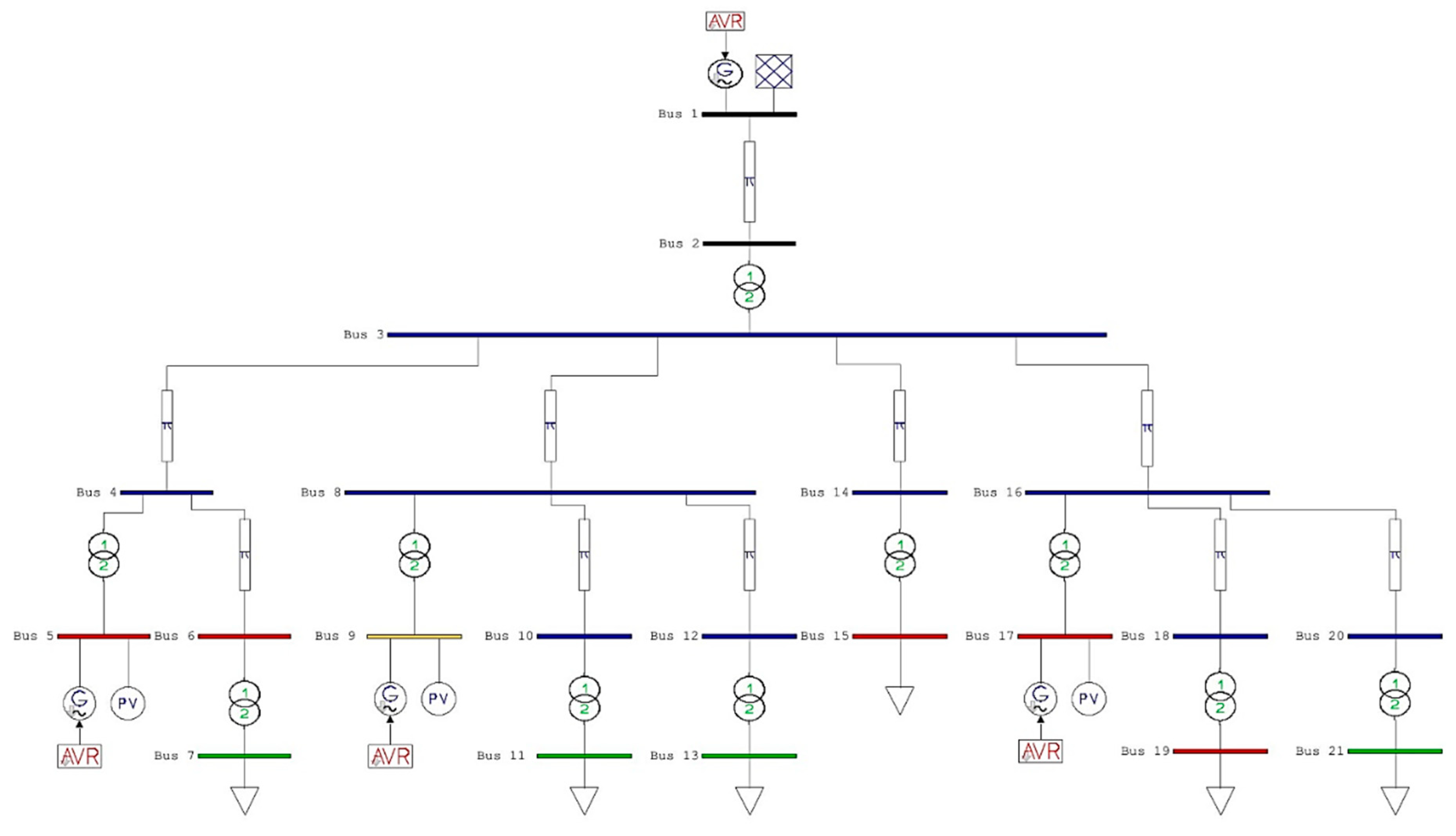
The IEEE 21-bus microgrid illustrated in
Figure 1 is used in this paper as a test system for the MFC strategy. It has three generators at buses 5, 9, and 17, and six loads at buses 7, 11, 13, 15, 19, and 21. More details and analysis of the 21-bus microgrid system data can be obtained in [
18].
Figure 2 shows the one-line diagram of the IEEE 21-bus microgrid system implemented using the Power System Analysis Toolbox (PSAT) software [
28]. PSAT is a MATLAB-based open source power system analysis toolbox. The provided Graphical User Interface (GUI) helps users to create Simulink-based system models by using its open component library and allows power flow, time domain simulation, and eigenvalue analysis, etc. [
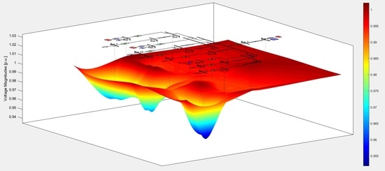
28]. By adding perturbation files to the simulation, new control algorithms and system disturbances can be implemented in the time domain simulation. The voltage magnitudes of all buses are plotted in
Figure 3 to illustrate the overall voltage profile of the IEEE 21-bus microgrid system under normal operating condition. Drastic load loss/increase conditions will be considered to investigate the voltage stability of the system. The effectiveness of the MFC strategy will be evaluated against such disturbances and compared with two other base cases, specifically the no-control case and the EMGVS case.
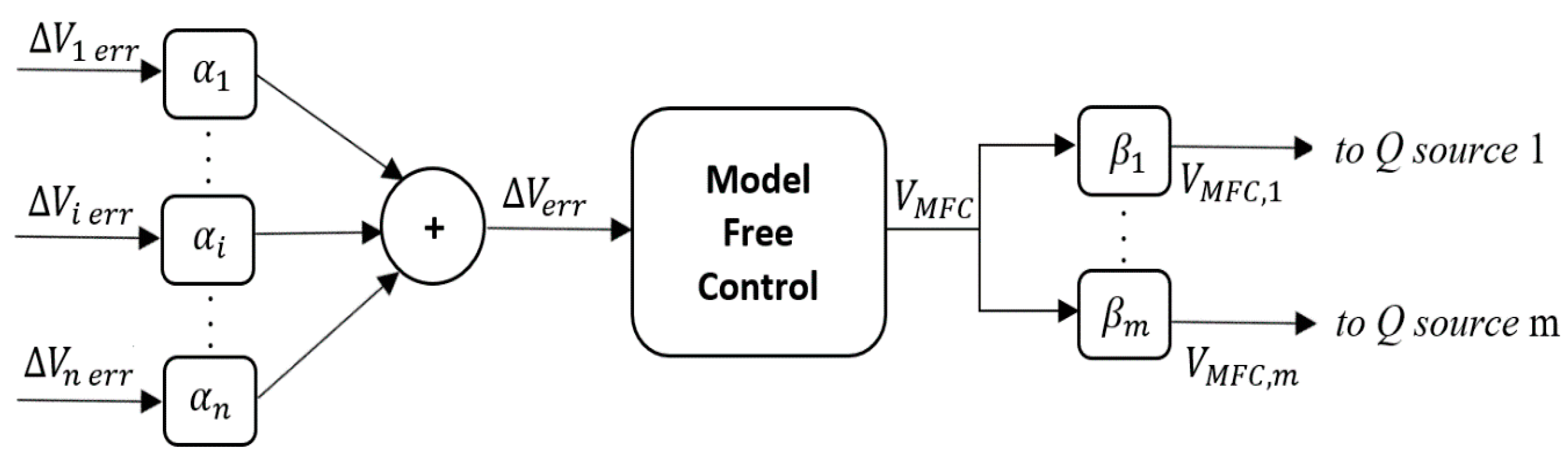
The microgrid load buses’ voltage deficiencies are used as inputs to the MFC as illustrated in
Figure 4. The difference (
) between the dynamic voltage (
) and the desired voltage (
) is computed for all load buses in per-unit as:
where the total number of load buses is
n. The weighting factors for all load buses are
which are based on the importance of the load bus (i.e., inductive loads are more sensitive to disturbances than resistive loads). A weighted average of
is considered to get an aggregate voltage deficiency,
of the system as:
Note that
is fed as an input to the MFC block. Remember that the objective of the MFC strategy is to let the load bus voltages track their corresponding desired voltages (set points); this is reflected by allowing the aggregate voltage deficiency
to be zero. The output of this MFC controller is
, as shown in
Figure 4.
is the overall MFC correcting signal allocated among all available DERs. The weighting factors,
for all generator DER buses (
to
) are contingent to the generation reserves and proximity of the DERs to inductive loads.
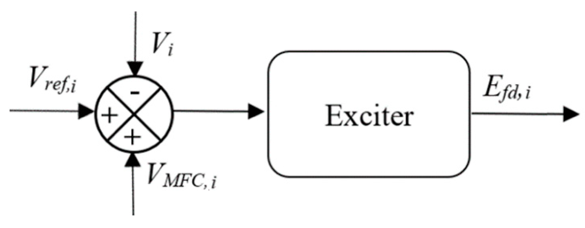
is described by:
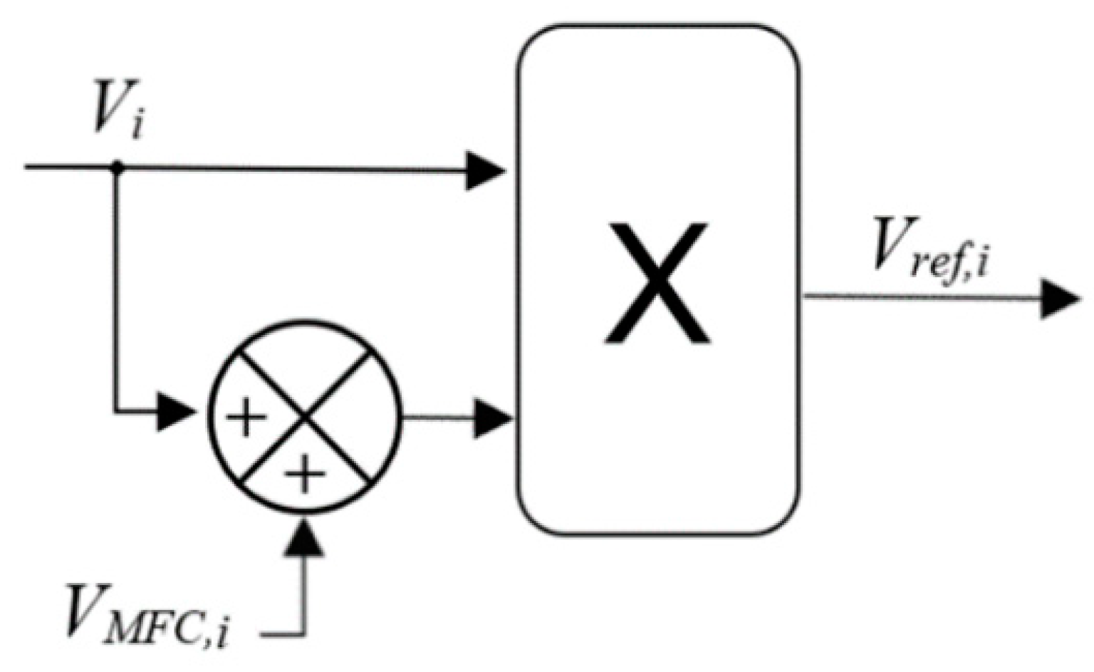
And it is the input to the
SG-based DER’s excitation system as shown in
Figure 5, or the input to the
PE-based DER to change the inverter’s voltage reference as shown in
Figure 6. Note that
Vi is the voltage of DER
i.
A pseudocode representation of the proposed MFC strategy for voltage control in a microgrid system is shown in Algorithm 1 below.
| Algorithm 1 MFC Strategy for Voltage Control |
| Input: , |
| Initialization: Determine the values for , L, ; obtain the past L values of system output (measurement) and input ; Set a = 0 and b = L. |
for l = 1, …, T Compute based on (6) and (7); Let . Define Y = [y(ta), …, y(tb)] and U = [u(ta), …, u(tb)]. Estimate F using Y and U based on (2). Compute the error . Compute the control gain based on (5). Obtain the control input based on (3); Let ; Compute based on (8). Update a = a + 1, b = b + 1.
|
| end for |
| Output: |
The following subsection describes the mathematical models for the SG-based and PE-based DERs. However, it is worth mentioning that the description of such models is to simulate and validate the control capability of the MFC strategy under various conditions and scenarios. In practical implementations, the need for any detailed and good modelling is not necessary since the MFC strategy does not require any system modelling (only requires input-output measurements).
2.3. SG-Based DER Model
SG-based DERs utilizing diesel engine generators (DEGs) are broadly utilized in remote locations, such as households, commercial, and industrial operational applications. A DEG consists of a synchronous generator and a prime mover as shown in
Figure 7. The diesel internal combustion engine works as a prime-mover and it is coupled to the generator. A permanent magnet generator with a rectifier and a voltage source converter may also be utilized. An SG is mostly utilized because it does not necessitate expensive PE devices such as voltage source inverters (VSIs). As the prime-mover and the generator are mechanically coupled, the dynamics of the SG are not electrically decoupled from the dynamics of the generator. The governor helps the prime mover to regulate the frequency and the exciter helps the generator to sustain the voltage output [
29].
An SG is an important active and reactive power generation unit for a microgrid. DEGs have slow responding governors as compared to other VSI-interfaced DEGs in microgrids. A DEG must run at high efficiency as the fuel cost increases with the use [
30,
31].
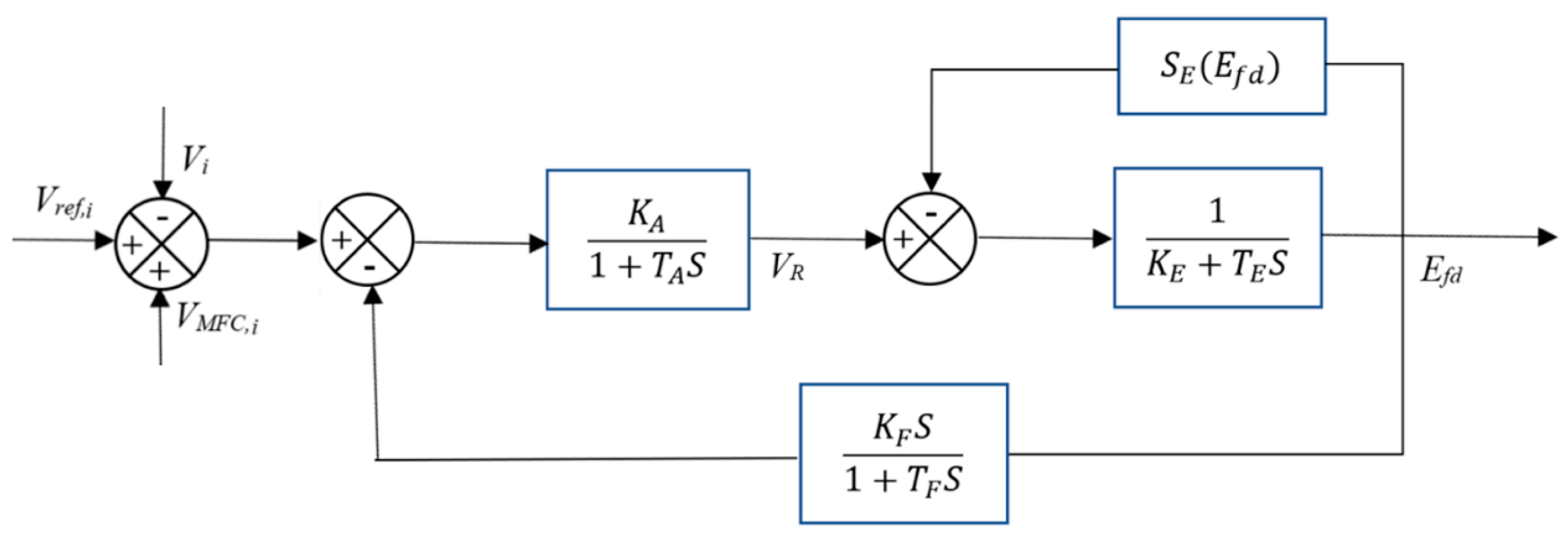
The d-q reference frame is used to model the SG, while the saturation and sub-transient reactance are neglected. The limit constraints on the pilot exciter of machine
i, output voltage
, and turbine governor dynamics affecting the mechanical torque
applied at the shaft are neglected. The next subsection covers the
m machine,
n bus system with the IEEE-Type I exciter differential and algebraic equations as illustrated in
Figure 8 [
29].
2.3.1. Differential Equations
The dynamics of the SG is represented by the differential Equations (9)–(12). The exciter dynamics are represented by the differential Equations (13) and (14), while Equation (15) represents the turbine governor dynamics.
where
are respectively the mechanical torque applied at the shaft, reference voltage, and voltage of machine
i.
are the q-axis and d-axis components of the internal voltage of machine
i.
are the speed of machine
i, synchronous speed, and machine angle, respectively.
are respectively the rate feedback, pilot exciter of machine
i output, and field voltage.
are the q-axis and d-axis armature currents of the machine at bus
i.
are the q-axis and d-axis reactance.
are the q-axis and d-axis transient reactance.
are the shaft inertia constant and damper constant.
are an exciter’s gain and time constants at machine
i.
are the self/separately excited gain and stabilizer time constants.
are the amplifier gain and time constant, respectively.
is the value of the saturation function at
which is ignored in this study [
29].
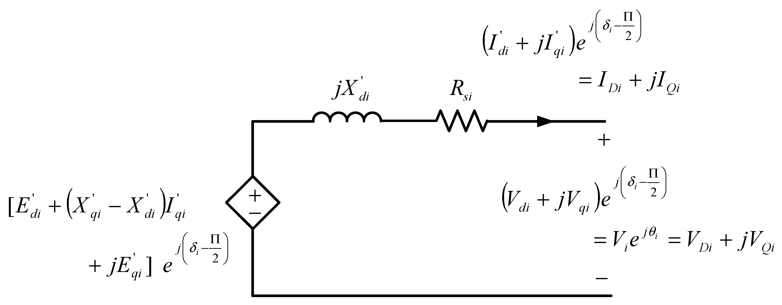
2.3.2. Algebraic Equations
The algebraic equations comprise the network and stator equations. The dynamic equivalent circuit shown in
Figure 9 is followed to derive the stator algebraic equations by applying Kirchhoff’s voltage law (KVL).
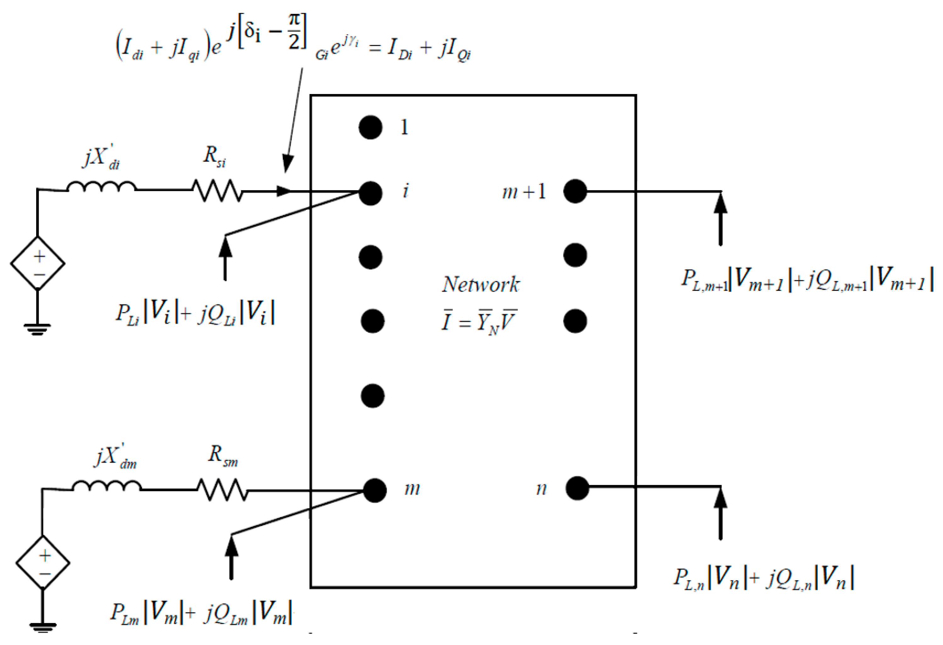
The dynamic circuit, together with the static network and the loads, are shown in
Figure 10. The network equations for the
n buses are in complex form. The following are the network equations for load buses.
While the generator buses’ network equations are:
where
are the voltage magnitude and angle at bus
i.
are the real and reactive components of loads at bus
i.
are the magnitude and angle of the admittance (Y
bus) matrix element at the
ith row and
jth column.
is the stator resistance of machine
i [
29].
2.4. PE-Based DER Model
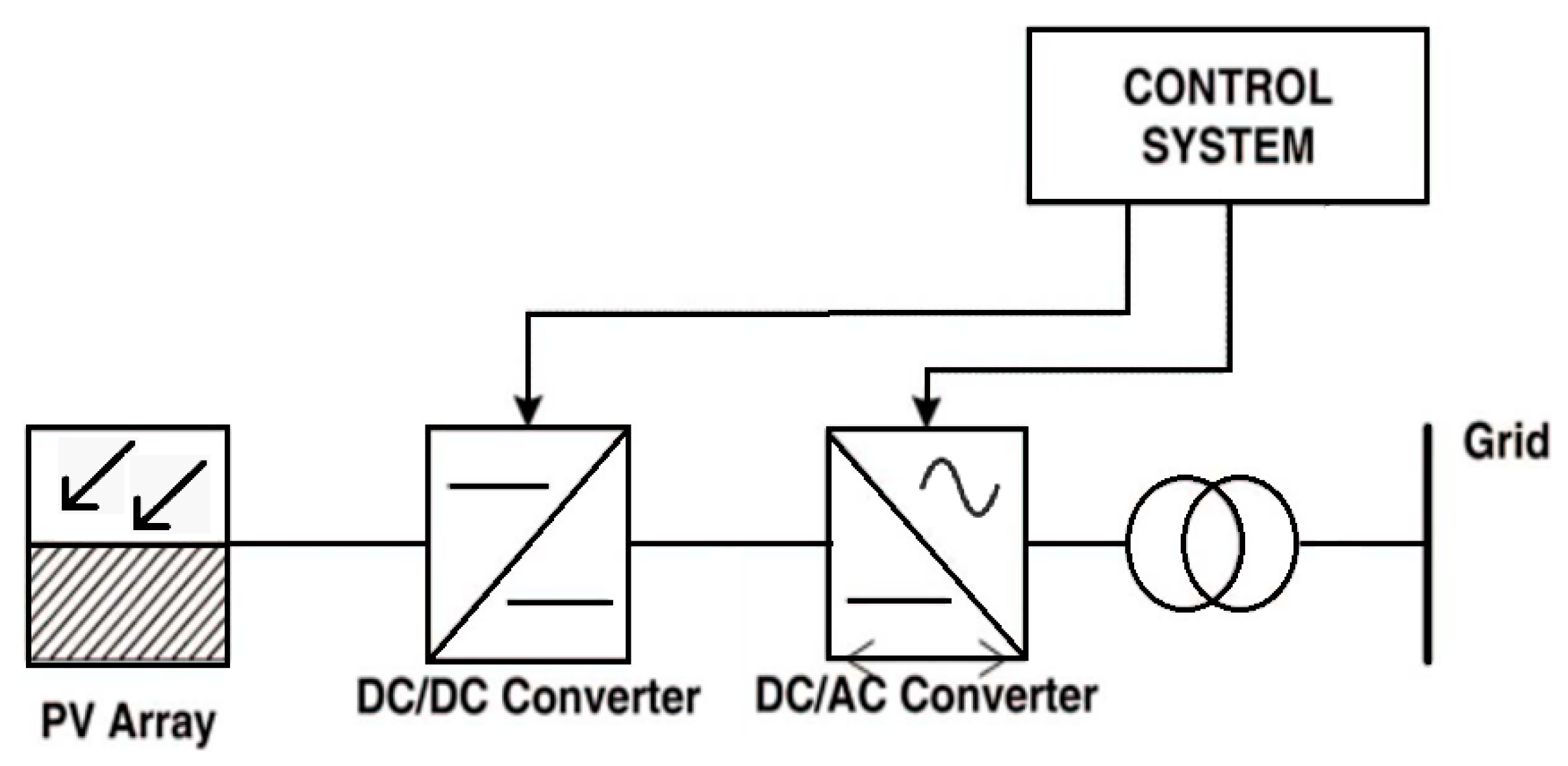
The structure of a grid-connected PE-based DER model utilizing solar photovoltaic generator (SPVG) is shown in
Figure 11. The PV array, DC/DC and DC/AC converters, and overall system control unit are the main subsystems of the structure [
32]. A DC/DC converter generally performs the maximum power point tracking (MPPT) to regulate the desired voltage level in SPVGs. The response of the MPPT is almost instantaneous for system stability analysis since there are no moving parts in such systems. The dynamic modelling requirements of other system components such as grid-connection devices, inverter, and DC bus are similar to the ones for the variable speed wind turbines.
The centralized SPVG farms are considered in this paper. The characterization of the system buses using two electrical quantities (out of
P,
Q,
V, and
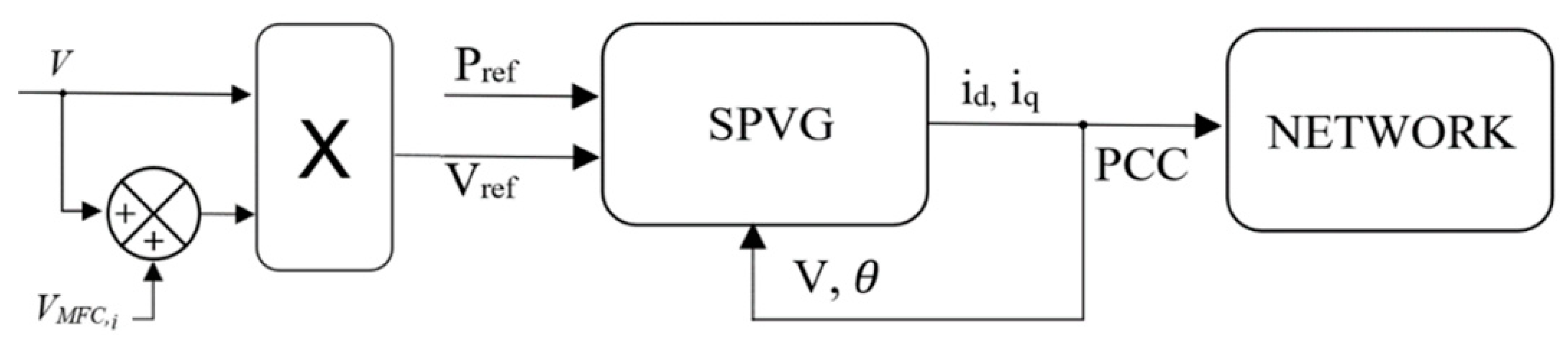
) is commonly applied. For the overall system study of a centralized SPVG, the buses are usually described as reactive power controls or active power injections with voltage magnitude. The distributed SPVG units, such as roof-top PVs, cannot regulate the network voltage at the connection point. Some limited voltage control may be considered based on centralized SPVG farms’ reactive power control capabilities. Accordingly, centralized farms can be modelled as constant P-Q or P-V generators (depending on the chosen control mode), and distributed SPVG units are modelled as constant P-Q negative loads [
33]. The functional model used in this paper is a constant P-V, as shown in
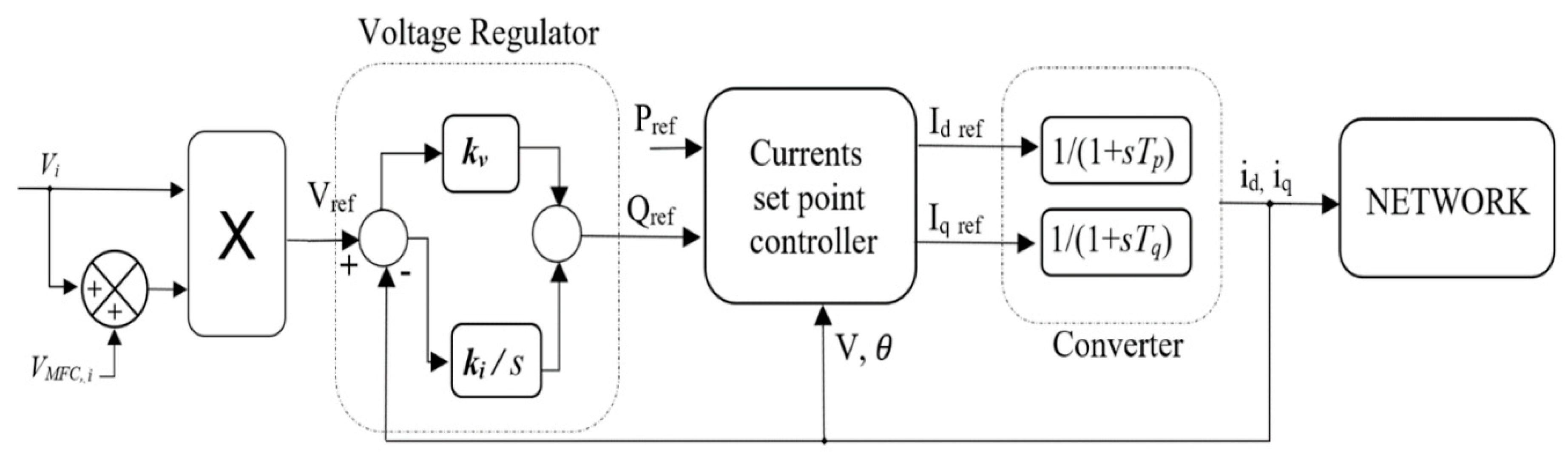
Figure 12, and its detailed block diagram is given in
Figure 13 [
34]. The closed-loop controller transfer function and the first-order function with unity steady-state gain are perhaps the most appropriate models for the inverter transfer function out of many other models [
35]. The first order function with unity steady-state gain model is used in this study. Additionally, the main inverter transient stability characteristics are captured by a first-order model. This approach is typically used in the modelling of voltage source inverters such as the static synchronous compensator (STATCOM) inverter models in [
36]. Note that the voltage regulator block in
Figure 13 is not part of the proposed MFC strategy, but it is part of the SPVG model so it can function in constant P-V mode. The current set points in this study can be obtained based on the measurements of the terminal voltage in the d-q reference frame and the desired active and reactive powers as:
This study assumes fixed or slow-changing power outputs for such models.
3. Simulation Studies and Discussions
The MFC strategy presented in
Section 2.2 is applied to tackle the major voltage stability problems of the DER-based IEEE 21-bus microgrid system in
Figure 1. The key parameters used for this study are tabulated in
Table 1.
The following three case studies are considered:
Case 1—Microgrid with two PE-based and one SG-based DERs.
Case 2—Microgrid with all PE-based DERs.
Case 3—Microgrid with all SG-based DERs.
The microgrid system has six loads at buses 7, 11, 13, 15, 19, 21, and three DERs (10 MVA each) at buses 5, 9, and 17. The effectiveness of the MFC control strategy has been investigated against a drastic load increase situation and compared to the EMGVS and no-control strategies. The overall dynamic voltage stability of the system has been investigated and evaluated with PSAT, a MATLAB-based time-domain dynamic simulation. The hardware environment is a laptop with Intel (R) CoreTM i7-8650U 1.90 GHz CPU, and 16.00 GB RAM.
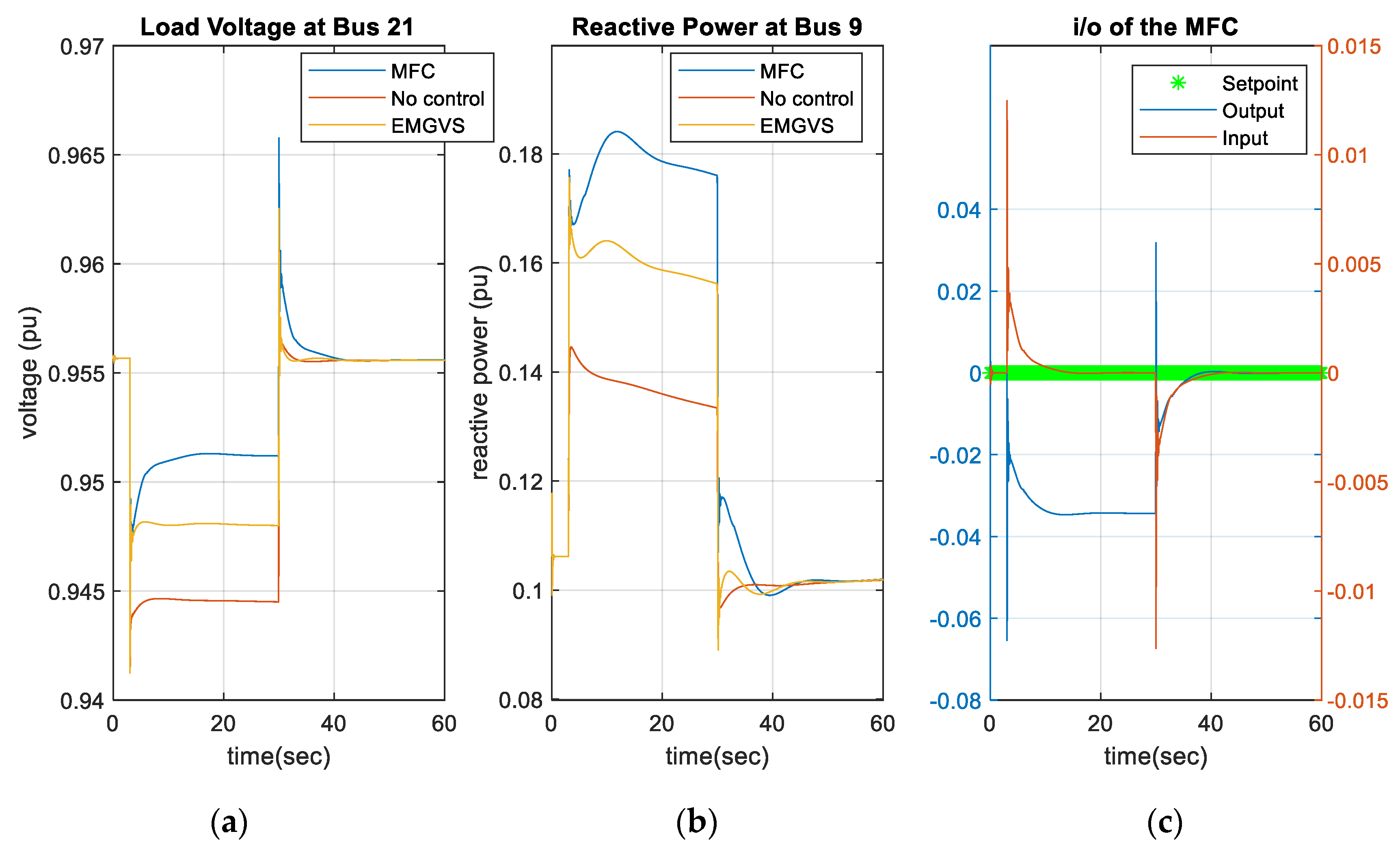
In Case 1, a microgrid system employing two PE-based DERs (PVs at buses 5 and 9) and one SG-based DER at bus 17 was investigated. The effectiveness of the MFC strategy was tested under a 25% load increase on all six load buses. The simulation time is considered as 60 s, where the disturbance occurred at
t = 3 s of the simulation time and lasted until
t = 30 s.
Figure 14 provides all the load bus voltages and reactive power generation of all the generation units.
In the remaining of this section, we focus on investigating the voltage at bus 21 since it has the lowest steady-state voltage point among other load buses. We also select the reactive power of the DER at bus 9 for further investigation. As illustrated in
Figure 15, the MFC provides the best load voltages while effectively controlling and coordinating the DERs’ reactive power generation. Moreover, the input, output, and desired trajectory (setpoint) of the MFC are shown in
Figure 15c to illustrate how closely the MCF follows the desired setpoint. The desired voltage trajectories,
for the MFC were set to the steady state values during the simulation. Such desired trajectories forced the aggregate voltage deficiency
to become zero in a short period of time. The correcting voltage signal generated from the MFC strategy properly changed the respected DERs’ excitation system voltage and the inverter voltage reference. As a result, the voltage fluctuations at load buses were minimized. The no-control strategy showed that the lack of proper correcting voltage signals to the DERs’ excitation system and the PE-based DERs’ inverter voltage reference caused a poor reactive power generation coordination. Thus, voltage violations observed at load buses. Furthermore, in this scenario, the EMGVS was not able to correct the voltage and bring it back to a value above 0.95 pu, which is the critical lower limit for voltage violation.
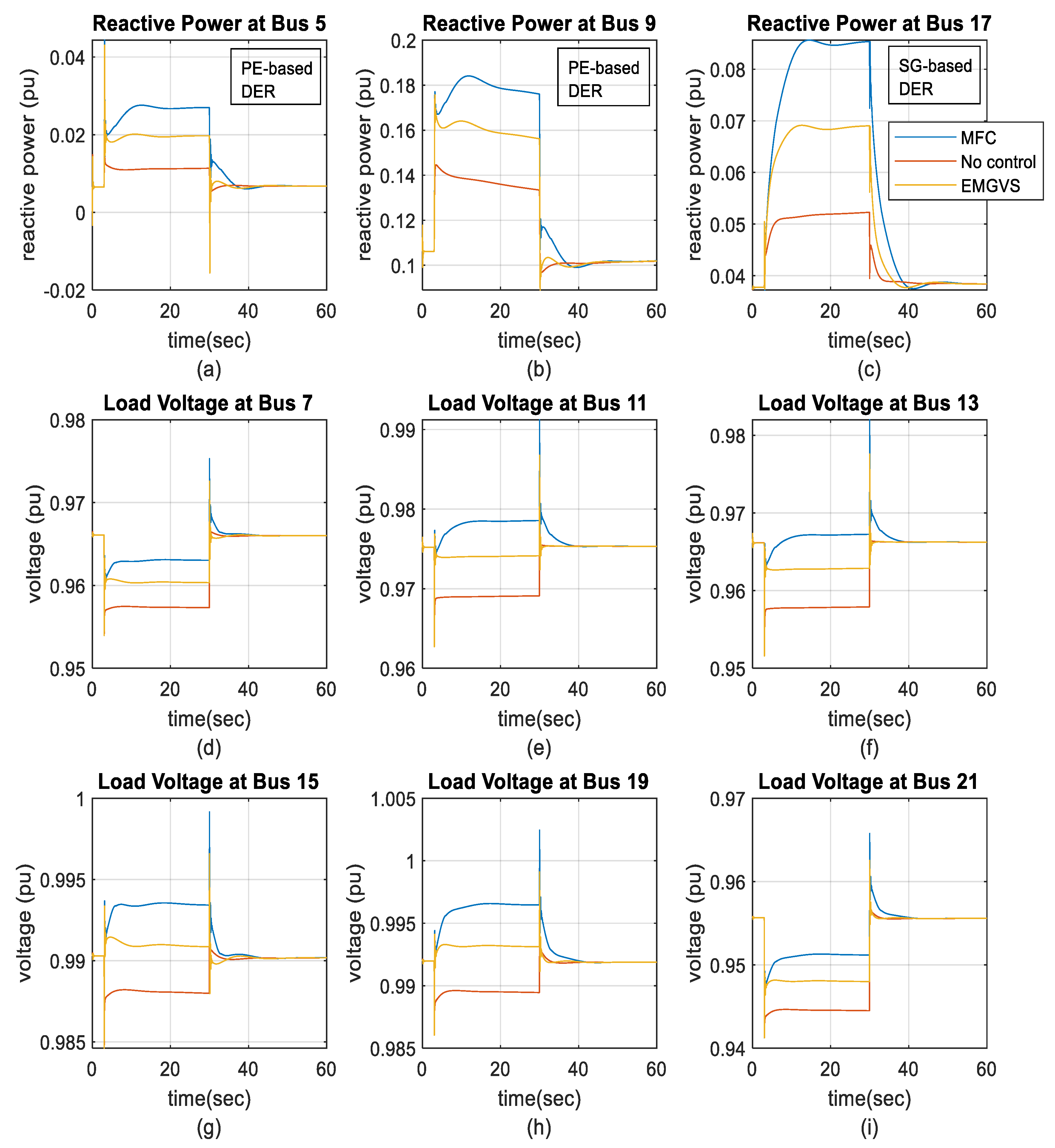
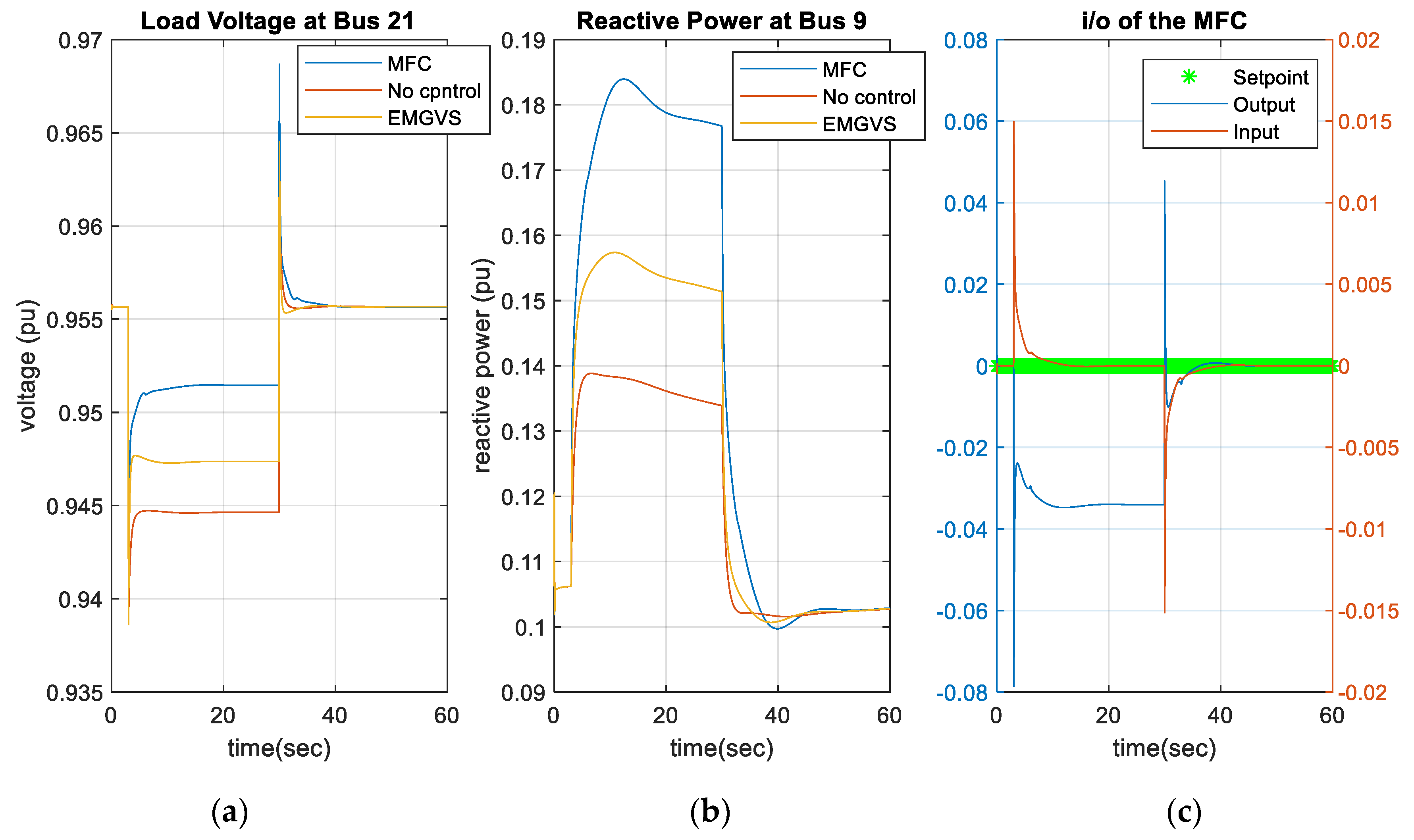
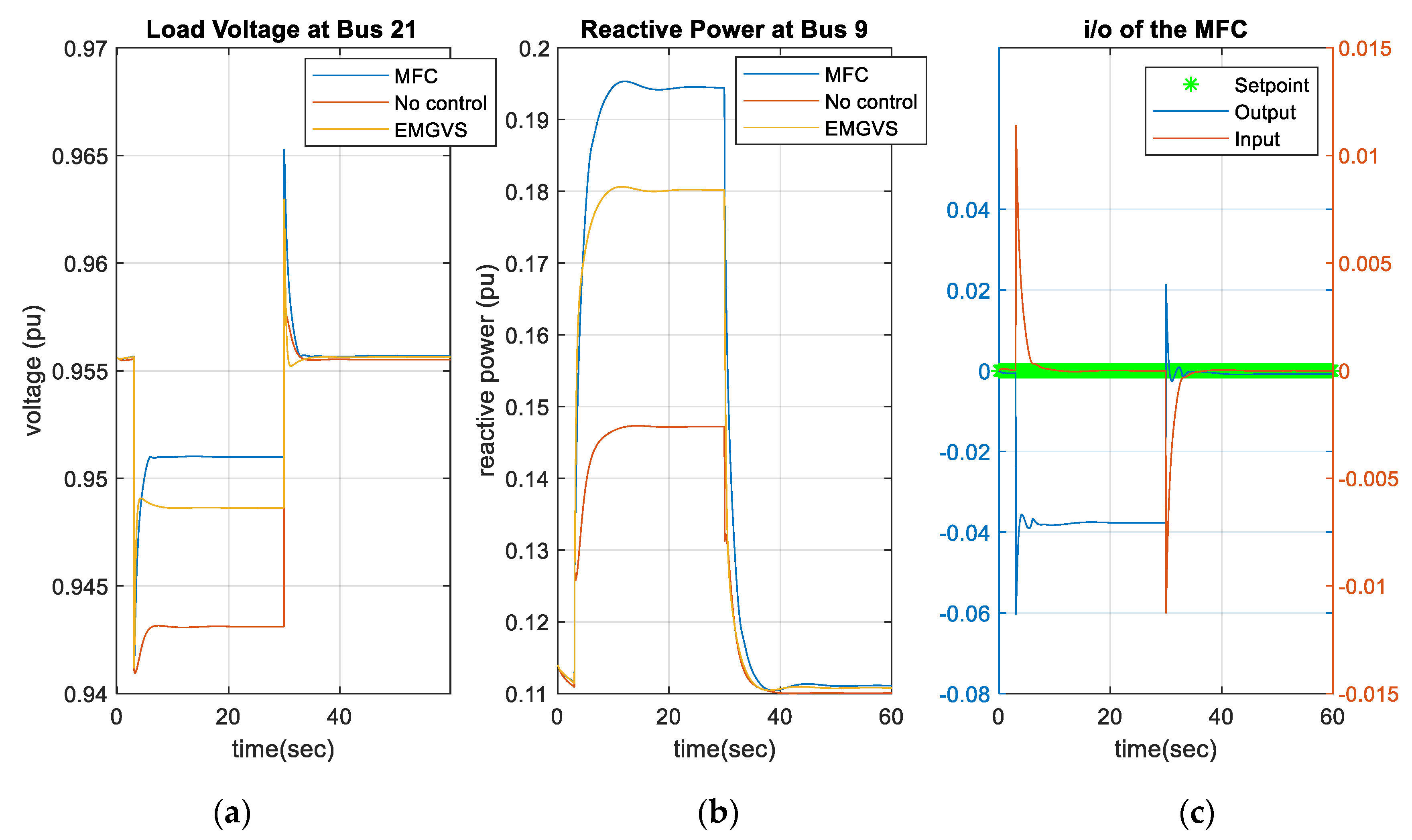
The simulation results for Case 2, where the microgrid system utilizing all PE-based DERs (PVs at buses 5, 9 and, 17), are shown in
Figure 16 under a 25% load increase at all load buses. In addition, the simulation results for Case 3, where the microgrid system using all SG-based DERs (SGs at buses 5, 9 and, 17), are shown in
Figure 17 under the same disturbance. Similar observations to Case 1 were witnessed in these cases, where they successfully demonstrate the effectiveness of the MFC strategy on dynamic voltage stability. Note that MFC does not need to have a system model or a transfer function for the microgrid system to operate. This feature is a major advantage of the MFC strategy over the EMGVS control strategy.
Under the used software and hardware resources, the computational time for each iteration (time step) for the MFC strategy was 0.017 s, while it was 0.216 s for the EMGVS control strategy. This illustrates the light computational requirement of the proposed MFC strategy, which makes it a good candidate for real-time applications.


