Article

Analysis of Multi-Phase Mixed Slurry Horizontal Section Migration Efficiency in Natural Gas Hydrate Drilling and Production Method Based on Double-Layer Continuous Pipe and Double Gradient Drilling

1
School of Mechatronic Engineering, Southwest Petroleum University, Chengdu 610500, China
2
Southern Marine Science and Engineering Guangdong Laboratory (Zhanjiang), Zhanjiang 524000, China
3
State Key Laboratory of Oil and Gas Reservoir Geology and Exploitation, Southwest Petroleum University, Chengdu 610500, China
*
Author to whom correspondence should be addressed.
Energies 2020, 13(15), 3792; https://doi.org/10.3390/en13153792
Submission received: 17 June 2020 / Revised: 14 July 2020 / Accepted: 16 July 2020 / Published: 23 July 2020

Abstract

:
In order to improve the recovery efficiency of natural gas hydrate in solid-state fluidized mining of natural gas hydrate, we solve drilling safety problems, such as narrow density of natural gas hydrate formation pressure window and poor wellbore stability caused by high upstream velocity during drilling and production. In this study—in order to increase the natural gas hydrate output and reduce production costs—based on the principle of the solid-state fluidized mining, a natural gas hydrate drilling method based on double-layer continuous-pipe double-gradient drilling was proposed to solve the above problems. The article introduces a drilling and production tool combination scheme and the mathematical model of wellbore-pressure dynamic regulation. Simulation software was used to study and compare the migration efficiency of multiphase mixed slurries of sediment and natural gas hydrates in the horizontal section of the double-layer continuous-pipe double-gradient drilling method and traditional drilling method. The results show that the transport efficiency of the multiphase mixed slurry of sediment and natural gas hydrate in the horizontal section of the double-layer continuous-pipe double-gradient drilling method is better than the traditional drilling method under the same conditions. When the double-layer continuous-pipe double-gradient drilling method is adopted, the multiphase mixed slurry of sediment and natural gas hydrate is transported in the pipe and has the function of the submarine lift pump, which effectively avoids the problem of the stability of the shaft wall caused by excessive flow velocity. This will also be more suitable for the transportation of large-diameter particles during the solid-state fluidized mining of natural gas hydrates.

Graphical Abstract

1. Introduction

As a new energy source, marine natural gas hydrate (NGH). may become a replacement energy source with huge reserves after shale gas and coal bed methane [1,2]. To date, for the exploitation of NGH with shallow seabed depth and poor cementation, traditional NGH drilling and production methods may lead to the disorderly decomposition of non-diagenetic NGH on the seabed, thereby affecting the stability of hydrate reservoir [3,4]. Therefore, based on the above reasons, Zhou Shouwei, an academician of the Chinese Academy of engineering, proposed solid-state fluidized mining (SSFM) method [5,6]. In May 2017, in the “Shen Hu Sea Area” of the South China Sea, SSFM was successfully implemented for the first time for deep-sea shallow non-diagenetic NGH, which proved the feasibility of “SSFM principles” for NGH. However, the drilling method used in this trial mining operation is a conventional drilling method, which mainly has the following problems: (1) the produced fluid has high sand content and low NGH recovery efficiency; (2) the NGH layer has a narrow pressure window density and is easy to leak; (3) the borehole wall stability of the open hole section is poor, and the produced fluid has a fast return flow rate. It is easy to cause the collapse of the shaft wall and bury the underground tools [7,8]. Therefore, in view of the above engineering problems, the NGH drilling and production method based on double-layer continuous-pipe double-gradient drilling (DDG) method has been proposed.
To date, there are many studies on double-gradient drilling technology, mainly focusing on reverse-circulation drilling technology, continuous-pipe double-gradient drilling technology and controlled-annulus drilling-fluid-level double-gradient drilling technology, etc. However, the DDG method is mainly used in the drilling and production of NGH. There is almost no research on this process. Different from the conventional drilling method for hydrate drilling, the DDG method is to pass drilling fluid from the annulus in the double-layer continuous pipe, and the multiphase mixed slurry of sediment and NGH returns to the ground from the double-layer continuous pipe inner pipe. In addition, this process can also achieve dynamic pressure control of the entire wellbore. Therefore, the adoption of this process can not only alleviate the problem of easy leakage of drilling fluid due to the narrow pressure window density of the hydrate formation, but also improve the stability of the well wall. Although this method realizes the migration of the produced multi-phase mixed slurry in the double-layer continuous pipe, it effectively avoids the problem of shaft wall collapse caused by the excessive annulus flow rate in the conventional method. However, whether the migration efficiency of DDG method is higher than that of traditional mining method remains to be analyzed and verified.
To date, there are relatively few studies on the migration process of NGH in the horizontal section. The horizontal section of the DDG method is mainly solid–liquid two-phase flow, which is similar to the cutting migration process in the traditional drilling method. The research on cuttings in the wellbore annulus mainly includes: Milad Khatibi, Rune W. Time, Rashid Shaibu et al. [9] studied the migration characteristics of debris inside inclined pipes and horizontal pipes under the action of laminar flow and turbulence and conducted experimental verification. Mehmet Sorgun, Ismail Aydin, M. Evren Ozbayoglu et al. [10] obtained the effects of flow velocity, rock cuttings concentration, pipeline inclination angle and rotation speed on the friction pressure loss inside the pipeline through experimental studies, and the empirical expressions of friction coefficients for low-viscosity and high-viscosity fluids are also proposed. Salah Zouaoui, Hassane Djebouri, Kamal Mohammedi et al. [11] studied the hydraulic transport characteristics of large spherical particles inside horizontal pipes. Zhu Xiao-hua, Li Jia-nan, Tong Hua et al. [12] analyzed the sand particle movement law and the influencing factors of the swirl field based on the two-phase flow theory. The above research is mainly focused on the study of the migration characteristics of debris particles in horizontal pipelines or horizontal wells. However, the research on the migration characteristics and efficiency of the multiphase mixed slurry of sediment and NGH in the horizontal well section has not been carried out.
The study is organized as follows. In Section 1, based on the principle of the NGH SSFM, a new technology of DDG method is proposed. The research status of the multiphase mixed slurry of sediment and NGH in horizontal section is also introduced. In Section 2, the DDG method and its pressure control model are introduced. In Section 3, the transport process of the multiphase mixed slurry of sediment and NGH in horizontal section of conventional drilling technology and DDG method and the stress situation between particles are introduced. In Section 4, the physical model and mathematical model of the multiphase mixed slurry of sediment and NGH are established. In Section 5, the migration efficiency of the multiphase mixed slurry of sediment and NGH in horizontal section of conventional drilling technology and DDG method is compared and analyzed. Finally, Section 6 provides some discussions and conclusions.

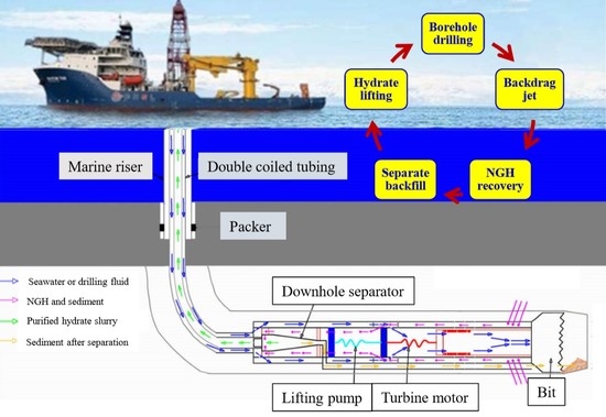
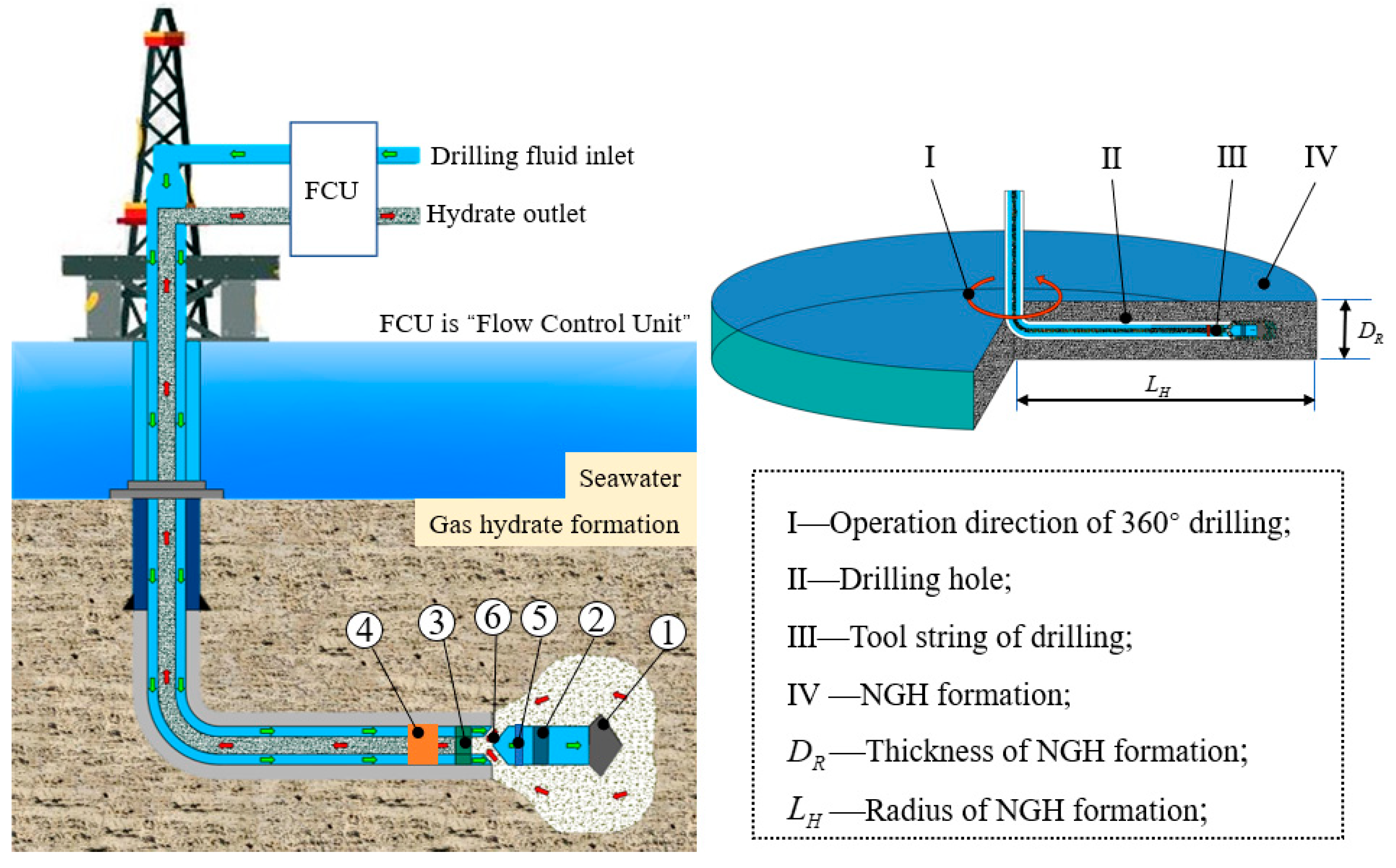
2. NGH Drilling and Production Method with DDG

2.1. The DDG Method

The core of the principle of NGH SSFM production is to use the stability of temperature and pressure of NGH in the reservoir to crush the sediment containing NGH into fine particles, mix them with seawater, and then transport them to the offshore platform by closed pipeline. Then the postprocessing and processing are carried out on the offshore platform [13]; its operation process is shown in Figure 1. Aiming at the problems of shallow burial depth of NGH in deep water, non-diagenesis and high sand content, the DDG method suitable for SSFM of NGH is proposed. The advantages of DDG is that it cannot only improve the migration and recovery efficiency of the multiphase mixed slurry of sediment and NGH, but also solve the problem of wellbore stability caused by high flow rate in horizontal section of traditional drilling method. It can also control the wellbore pressure and realize 360° drilling and production of NGH reservoir. The operation process includes the following three stages.
Stage I (drilling process): First, the NGH drilling and production ship is driven to the NGH mining area, and the NGH drilling and production ship is anchored. Then the double-layer continuous pipe and drilling tool string are lowered to the bottom of the sea to drill the horizontal well of NGH reservoir, so as to form the channel of NGH jet breaking.
Stage II (mining and recovery process): First, the flow of seawater pumped into the drilling tool by the high-surface pump set is increased, so that the seawater drives the internal sliding core of the pressure controlled sliding sleeve to the right (as shown in Figure 1 and Table 1). At this time, the sliding core will block the drilling fluid leading to the drill bit and at the same time open the drilling fluid channel leading to the high-pressure jet nozzles. The drilling fluid is jetted out of the jet nozzle at high speed to rotate the circumferential hydrate to break up the hydrate to form a crushing cavity. The mixed slurry of the NGH and sediment is pumped into the inner pipe of the double-layer continuous pipe through the bridge channel under the suction action of the lifting pump and moved to the downhole NGH separator. The separator separates the mixed slurry of the NGH and sediment. The separated NGH enters the NGH storage tank through the inner tube of the double-layer continuous tube. The separated sediment is discharged into the mined area through the sediment backfill channel.
Stage III (comprehensive mining process): Repeat stage I and II to implement 360° drilling and production operation in NGH reservoir.

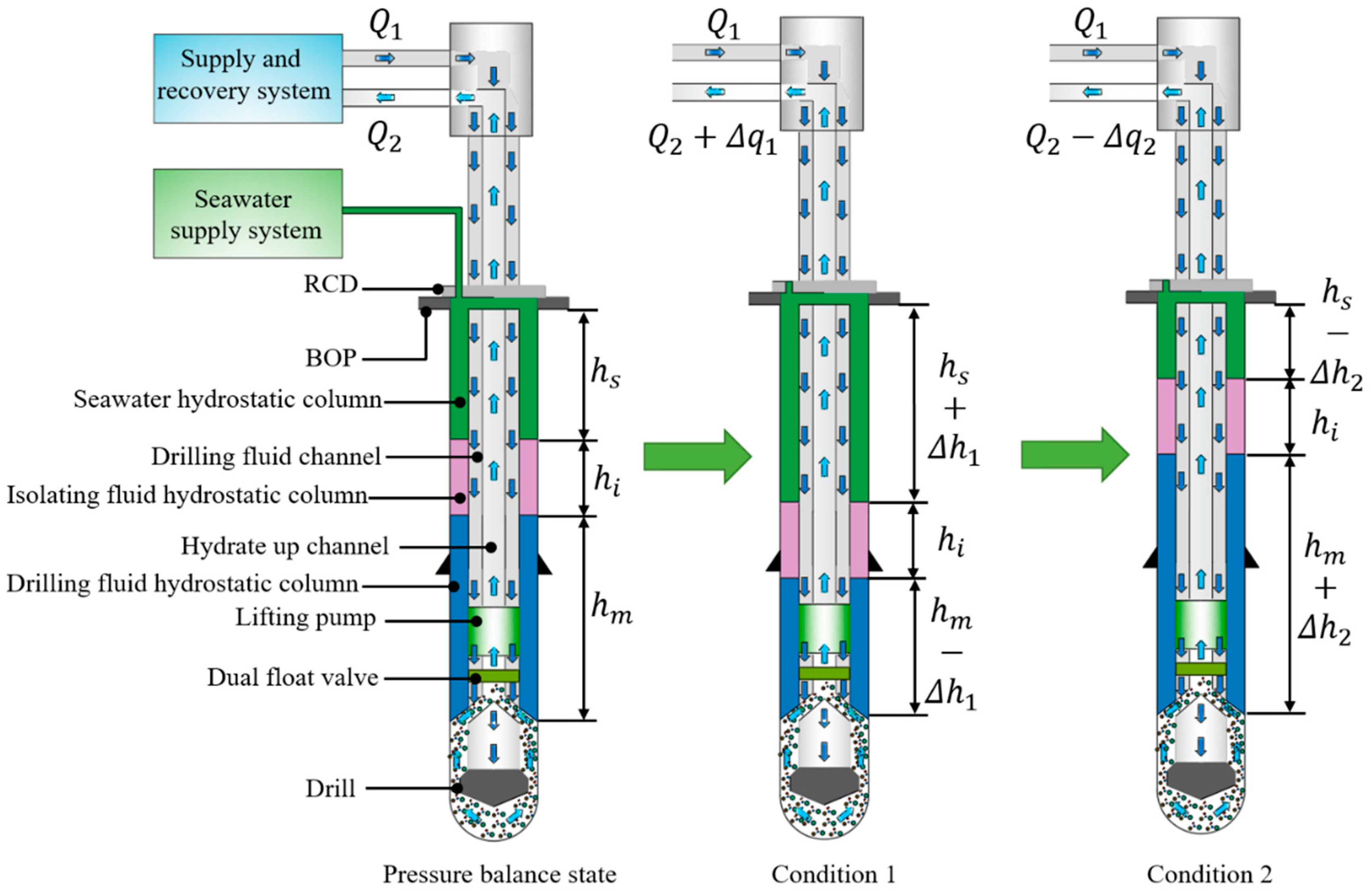
2.2. Dynamic Regulation of Wellbore Pressure

Due to the narrow pressure window of the NGH formation, leakage and overflow are prone to occur during drilling operations. If the bottom well pressure is not accurately controlled, it will cause a very serious safety problem. During the actual operation:
Δ P w i n d o w = min ( P f , P L e a k ) max ( P p r o , P c p )
where, Δ P w i n d o w is the safety differential pressure window of formation pressure; P f is formation fracture pressure; P L e a k is formation loss pressure; P p r o is formation pore pressure; P c p is formation collapse pressure.
Therefore, in order to achieve precise drilling pressure control and achieve the goal of safely controlling the bottom pressure of the well bore, the bottom pressure of the well bore should meet:
max ( P p r o , P c p ) P b min ( P f , P L e a k )
where, P b is the bottom pressure of the well bore.
As shown in Figure 2, the bottom pressure of the well bore is mainly composed of seawater pressure, isolation fluid pressure and drilling fluid pressure, and its expression is:
P b = ρ s g h s + ρ i g h i + ρ g h m
where: ρ s is the density of seawater, ρ i is the density of isolation fluid; ρ m is the density of drilling fluid; h s is the height of seawater, h i is the height of isolation fluid; h m is the height of drilling fluid, respectively; g is the acceleration of gravity.
It can be seen from the expression (3) that to adjust the bottom pressure of the well bore, the bottom pressure of the well bore can be adjusted by changing the height and density of each hydrostatic column section. This process is mainly a process of adjusting the bottom pressure of the well bore by adjusting the height of the hydrostatic column, so that the bottom pressure of the well bore changes dynamically.
When the bottom pressure of the well bore is too high, resulting in serious leakage, the height of the drilling fluid hydrostatic column can be reduced to increase the seawater hydrostatic column height to reduce the bottom pressure of the well bore. The expression is:
P b 1 = ρ s g ( h s + Δ h 1 ) + ρ i g h i + ρ m g ( h m Δ h 1 )
where, P b 1 is the pressure value after the bottom pressure of the well bore is reduced; Δ h 1 is the reduced height of the drilling fluid hydrostatic column; Since the density of seawater is less than the density of drilling fluid, so P b 1 < P b .
When the bottom pressure of the well bore is too low, resulting in serious overflow conditions, the height of the drilling fluid hydrostatic column can be increased to decrease the seawater hydrostatic column height to increase the bottom pressure of the well bore. The expression is:
P b 2 = ρ s g ( h s Δ h 2 ) + ρ i g h i + ρ m g ( h m + Δ h 2 )
where, P b 2 is the pressure value after the bottom pressure of the well bore increases; Δ h 2 is the increased height of the hydrostatic column; Since the density of seawater is less than the density of drilling fluid, so P b 2 > P b .
The adjustment of the height of the hydrostatic column is mainly through the adjustment of the speed of the submarine drilling lift pump and the working series of the series pump, changing the flow rate and head of the pump, so as to realize the adjustment of the height of the hydrostatic column of the drilling fluid. The specific process is shown in Figure 2. In the state of pressure balance, the flow rate of drilling fluid from the outer layer of the double-layer continuous pipe is Q 1 , and the flow rate from the inner layer of the double-layer continuous pipe is Q 2 .
Condition 1.
When the bottom pressure of the well bore is too high to cause a leak, the rotation speed of the lift pump can be adjusted so that the flow rate of the inner tube of the double-layer continuous tube is:
Q 2 = Q 2 + Δ q 1
where, Q 2 is the flow rate returned from the inner tube of the double-layer continuous tube in condition 1. Δ q 1 is the increase of the flow rate returned from the inner tube of the double-layer continuous tube after adjusting the speed of the lift pump.
Condition 2.
When overflow occurs when the bottom pressure of the well bore is too low, the speed of the lift pump can be adjusted so that the flow rate of the inner tube of the double-layer continuous tube is:
Q 2 = Q 2 Δ q 2
where, Q 2 is the flow rate returned from the inner tube of the double-layer continuous tube in condition 2. Δ q 2 is the reduction of the flow rate returned from the inner tube of the double-layer continuous tube after adjusting the speed of the lift pump.

3. Analysis of the Mechanism of the NGH Slurry Migration in Horizontal Section

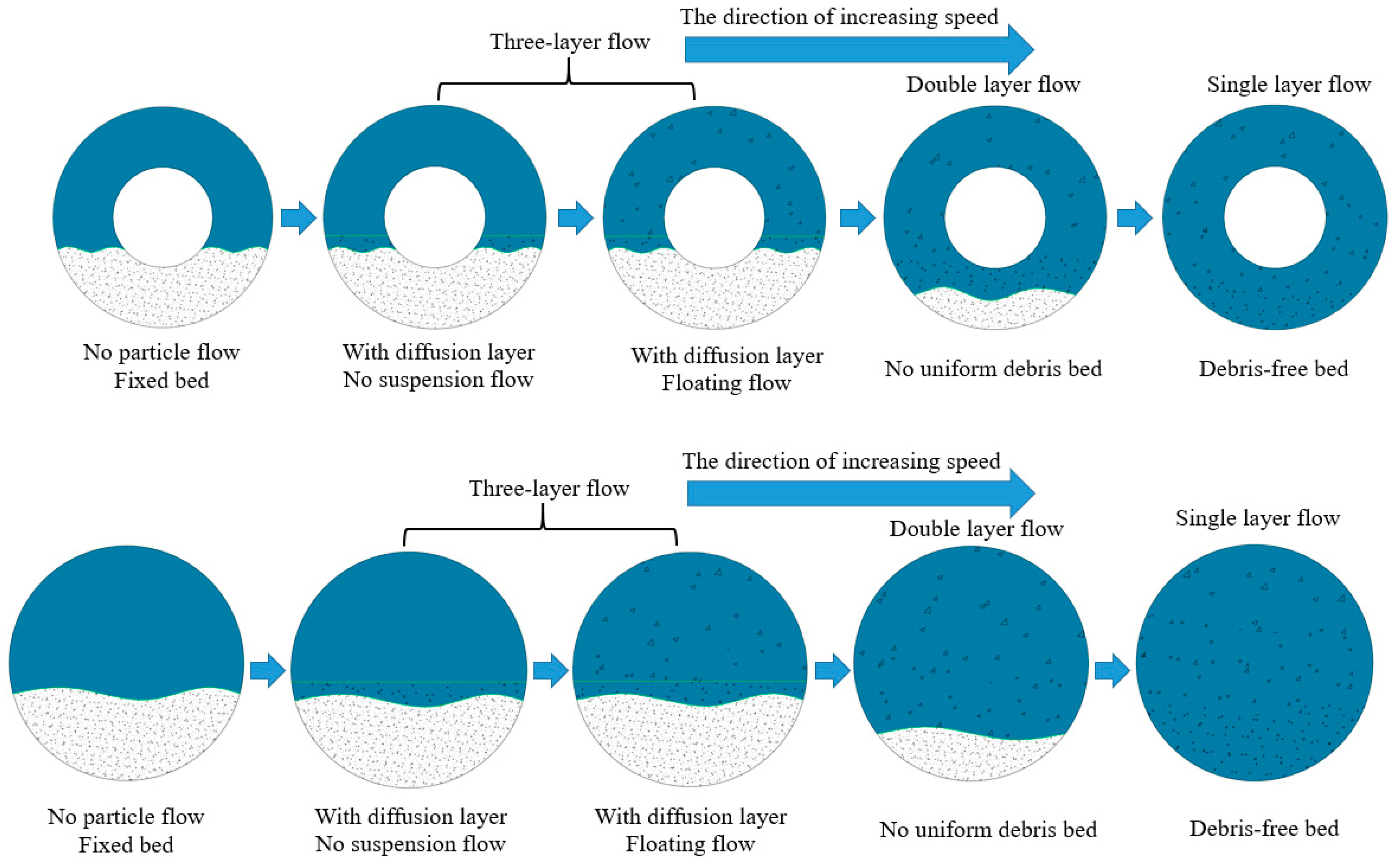
3.1. Analysis of the NGH Slurry Migration State in Horizontal Section

3.1.1. Migration State under Different Working Conditions

When the NGH is on the sea floor, the environment temperature and pressure are relatively stable, and the amount of NGH decomposition is relatively small. Therefore, in the horizontal section, the migration process of NGH can be simplified from gas–liquid–solid three-phase flow to solid–liquid two-phase flow [14].
As the sedimentation direction of the multiphase mixed slurry of sediment and NGH is perpendicular to the flow direction of fluid, and its synthesis speed direction points to the lower side of the wellbore, it is easy to form a sedimentary bed in the horizontal section. With the increase of drilling fluid flow rate, the migration process of solid particles will be divided into several types as shown in Figure 3 [15].
Type 1: When the flow rate of drilling fluid is very low, the drag force and uplift force generated by the drilling fluid are not enough to overcome the gravity and resistance to make the particles on the surface of cuttings bed move, so the cuttings bed is in a static state.
Type 2: With the increase of flow rate, the solid particles on the surface of cuttings bed begin to be lifted, thus forming a diffusion layer. However, at this time, the flow rate of drilling fluid is not enough to make the solid particles completely suspended in the drilling fluid, thus moving forward with the drilling fluid. Therefore, the fluid on the upper part of the diffusion layer can be regarded as pure fluid without solid particles.
Type 3: The flow rate of drilling fluid is further increased, and the particles of diffusion layer enter into the drilling fluid under the action of fluid to form suspension layer. Finally, a fixed bed, a diffusion layer and a suspension layer are formed inside the wellbore.
Type 4: The flow rate of drilling fluid is further increased, and all solid particles enter the diffusion layer. The fixed bed disappears, only the diffusion layer and suspension layer remain.
Type 5: The flow rate of drilling fluid continues to increase, and all particles in the diffusion layer enter the upper fluid to move forward in a suspended state. Only suspended layer is left.

3.1.2. Slurry Migration State in Different Methods

When the traditional drilling method is used, the solid particles such as NGH and sediment are transported in the annulus of horizontal section. Because the surface of borehole section is rough and uneven, the particles mainly move in the form of rolling and jumping, and the cuttings under the bed surface are still static. When the velocity reaches a certain degree, the movement develops to the deep layer because of the increase of fluid drag force and the momentum exchange between the particles in each layer, and finally forms the layer rolling migration of solid particles. When the flow velocity is large enough, under the influence of fluid-lift and radial pulsation, the exchange of momentum and mass occurs simultaneously among the layers of solid particles. Finally, the solid particles enter the state of suspension and migration, as shown in Figure 4 [16,17,18].
When the DDG method are used, the solid particles such as NGH and sediment are transported in inner pipe of double-layer continuous pipe in the horizontal section. Because the inner surface of continuous pipe is relatively smooth, and the solid particle migration channel size of DDG method is smaller than that of traditional drilling method, as shown in Figure 5. Therefore, under the same conditions, the internal flow velocity of the DDG method is relatively high. Under the influence of fluid-lift and radial pulsation, the exchange of momentum and mass exchange between solid particles. The particles finally enter the suspended migration state. In addition, the DDG method is also provided with a lift pump device for assisting the return of the multiphase mixed slurry of sediment and NGH in the horizontal section, which will also have a beneficial effect on the migration of solid phase particles in the horizontal section [19,20].

3.2. Force Analysis of Solid Particles in Horizontal Section

In order to reveal the migration process of the solid particles contained in the mixed slurry of NGH and sediment under the action of drilling fluid, a stress analysis of the solid particles was performed. Suppose that the solid particles in the hydrate mud sand multi-phase mixed slurry are spherical. It is found that the stress analysis of the solid phase particles is mainly affected by gravity, buoyancy, hydraulic drag force, hydraulic lifting force, hydrostatic column pressure and viscous force during the horizontal section migration [21,22]. The specific force situation is shown in Figure 6.
1.
The gravity G and buoyancy F B of the solid particles in the drilling fluid are:
G = π 6 d p 3 ρ s g
F B = π 6 d p 3 ρ l g
where: d p is particle size of the solid phase, m; ρ s is density of the solid phase particles, kg/m3; ρ l is drilling fluid density, kg/m3.
2.
The hydraulic drag force F D and hydraulic lift force F L of the solid particles in the drilling fluid are:
F D = 1 2 C D ρ f v 2 π d p 2 4
F L = 1 2 C L ρ f v 2 π d p 2 4
where: C D = a D ( d p d ) 1 / 3 , C D = a L ( d p d ) 1 / 3 ; C D is drag coefficient; C L is the lift coefficient; d is a constant related to d p , when d p ≤ 0.5 mm, d = 0.5 mm; When 0.5 < d p < 10 mm, d = d p ; When d p 10 m m ; a D and a L is constant coefficient; v is instantaneous flow velocity acting on the particles, m/s.
3.
Cohesion F C between particles is:
F C = a c ( γ o γ o + ) 2.5 π 2 ρ ε d p
where: a c is constant coefficient; γ o is dry bulk density of the particles, kg/m3; γ o + is stable dry bulk density of the particles, kg/m3; ε is the bonding force parameter, for natural sand, generally take 1.7510−6 × m3/s2.
4.
Pressure gradient force F P
The pressure gradient is generated by the wellbore drilling fluid pressure gradient, and the force direction is along the drilling fluid flow direction. The expression is:
F P = π 6 d p 3 F d p
where: F d p is the pressure gradient, Pa/m.

4. Establishment of Numeric Simulation Model of NGH Slurry Migration Process

4.1. Physical Model

4.1.1. Basic Assumptions

Make the following assumptions based on the actual engineering and calculation requirements:
  • The fluid does not undergo a phase change during the flow process. The wellbore is in adiabatic, and there is no heat exchange between the fluids in the annulus.
  • Solid particles have the same diameter, density and friction angle, and are spherical rigid particles.
  • Numeric simulation analysis of the fluid at the entrance is fully developed fluid.

4.1.2. Physical Model Building

In this study, the migration process of the multiphase mixed slurry of sediment and NGH is taken as the research object in the horizontal well section of two different drilling methods used in the process of SSFM NGH. The size of the horizontal section channel of the traditional method is the size adopted for the first SSFM operation of NGH in 2017, as shown in Table 2 and Figure 7.

4.2. Mathematical Model of Slurry Migration Process

4.2.1. Selection of Turbulence Model for Horizontal Slurry Migration Process

Although large eddy simulation and direct numeric simulation can accurately reproduce the turbulent flow field structure, for practical engineering problems, the huge amount of calculations makes it difficult to use these two methods generally. Therefore, in practical engineering, the use of turbulence model to deal with the problem is currently commonly used research methods [23]. In engineering problems, commonly used turbulence models mainly include: Standard k ε model, RNG k ε model and Realizable k ε model. However, the Standard k ε model assumes that the fluid is completely turbulent and ignores the effect of molecular viscosity. Its derivation depends on the observation of actual experience and experimental phenomena. However, the RNG k ε turbulence model has the same model as the Standard k ε model, but it considers the rotating and swirling flow in the average flow and corrects the turbulent viscosity, so it can better deal with the flow with high strain rate and large curvature of streamline. For the realizable model, because the influence of average rotation is considered in the definition of turbulent viscosity, the natural turbulent viscosity cannot be provided in the calculation of rotating and static flow areas [24,25,26].
Considering that the flow of drilling fluid in a well has typical turbulent characteristics with swirling flow. In this study, RNG k ε turbulence model is used to calculate the turbulent characteristics of the transport of the multiphase mixed slurry of sediment and NGH in the horizontal section.
The transport equation of the turbulent flow energy k and the turbulent flow energy dissipation rate ε of the RNG k ε model are [27,28]:
t ( ρ k ) + x i ( ρ k u i ) = x j ( α ε μ e f f x j ) + G k + G b ρ ε Y M + S k
t ( ρ ε ) + x i ( ρ ε u i ) = x j ( α ε μ e f f x j ) + C 1 ε ε k ( G k + C 3 ε G b ) C 2 ε ρ ε 2 k R ε + S ε
where, ρ is the drilling fluid density, k g / m 3 ; k is turbulent kinetic energy, m 2 / s 2 ; ε is the turbulent dissipation rate, m 2 / s 3 ; μ is the dynamic viscosity coefficient, k g / ( m s ) ; μ t is the residual viscosity, k g / ( m s ) ; u i is the average speed, m / s ; μ e f f is the coefficient of kinematic viscosity, m 2 / s ; G k is the term generated by the residual kinetic energy k caused by the average velocity gradient, J ; G b is the generation term of turbulent kinetic energy k caused by buoyancy, J ; Y M is the influence of the wave expansion of the compressible turbulence on the overall dissipation rate; α k is the turbulent Prandtl number of k ; α ε is the turbulent Prandtl number of ε ; S k and S ε is a user-defined source item; Among them, C 1 ε = 1.42 , C 2 ε = 1.68 , C 3 ε = 1.3 .

4.2.2. Selection of Multiphase Flow Models

To date, there are two kinds of numeric methods to deal with multiphase flow: Euler–Euler method and Euler-Lagrange method. In this study, the Euler–Euler method is used for the transport of the multiphase mixed slurry of sediment and NGH. In this method, the fluid phase is treated as a continuous phase, while the discrete phase is obtained by calculating the movement of a large number of particles in the flow field. Mass, momentum and energy can be exchanged between solid phase and continuous phase [29].
The main phase of the numeric simulation process is the drilling fluid and the secondary phase is the mixture of NGH and sediment. The continuity equation of the Euler- Euler model is:
( α l ρ l u l ) = m ˙ s l
( α s ρ s u s ) = m ˙ l s
where, m ˙ s l and m ˙ l s are the mass transferred between solid particles and drilling fluid.
The momentum equations of drilling fluid and solid particles in the Euler- Euler model are:
( α l ρ l u l u l ) = α l p + τ l ¯ ¯ + α l ρ l f α l ρ l ω × u l + α l ρ l ω 2 r + α l ρ l ( F l + F l i f t , l + F v m , l ) + [ K s l ( u s u l ) + m ˙ s l u s l ]
( α s ρ s u s u s ) = α s p + τ s ¯ ¯ + α s ρ s f α s ρ s ω × u s + α s ρ s ω 2 r + α s ρ s ( F s + F l i f t , s + F v m , s ) + [ K l s ( u l u s ) + m ˙ l s u l s ]
where, τ l ¯ ¯ is pressure and strain tensor of drilling fluid; τ s ¯ ¯ is pressure and strain tensor of solid particles; F l is the external volume force of drilling fluid, kg × m / s 2 ; F l i f t , l is lifting force, kg × m / s 2 ; F v m , l is virtual quality force, kg × m / s 2 ; u s l and u l s are the interphase velocity of drilling fluid and solid particles, m / s ; When m ˙ s l > 0 , u s l = u s ; When m ˙ s l < 0 , u s l = u l and u s l = u l s ; K s l and K l s are the momentum exchange coefficient between drilling fluid and solid particles.

5. Analysis of Numeric Simulation Results of NGH Slurry Migration Process

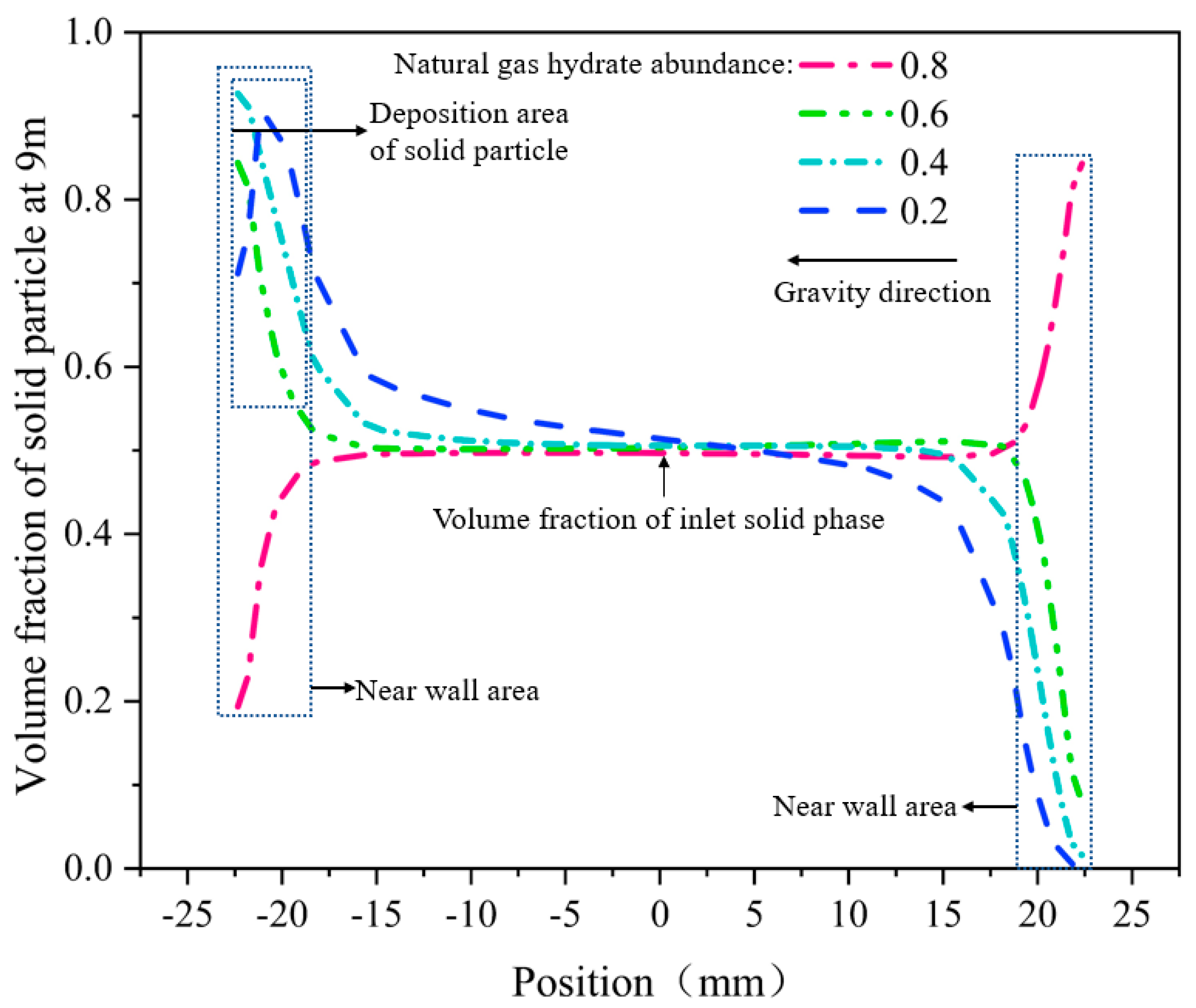
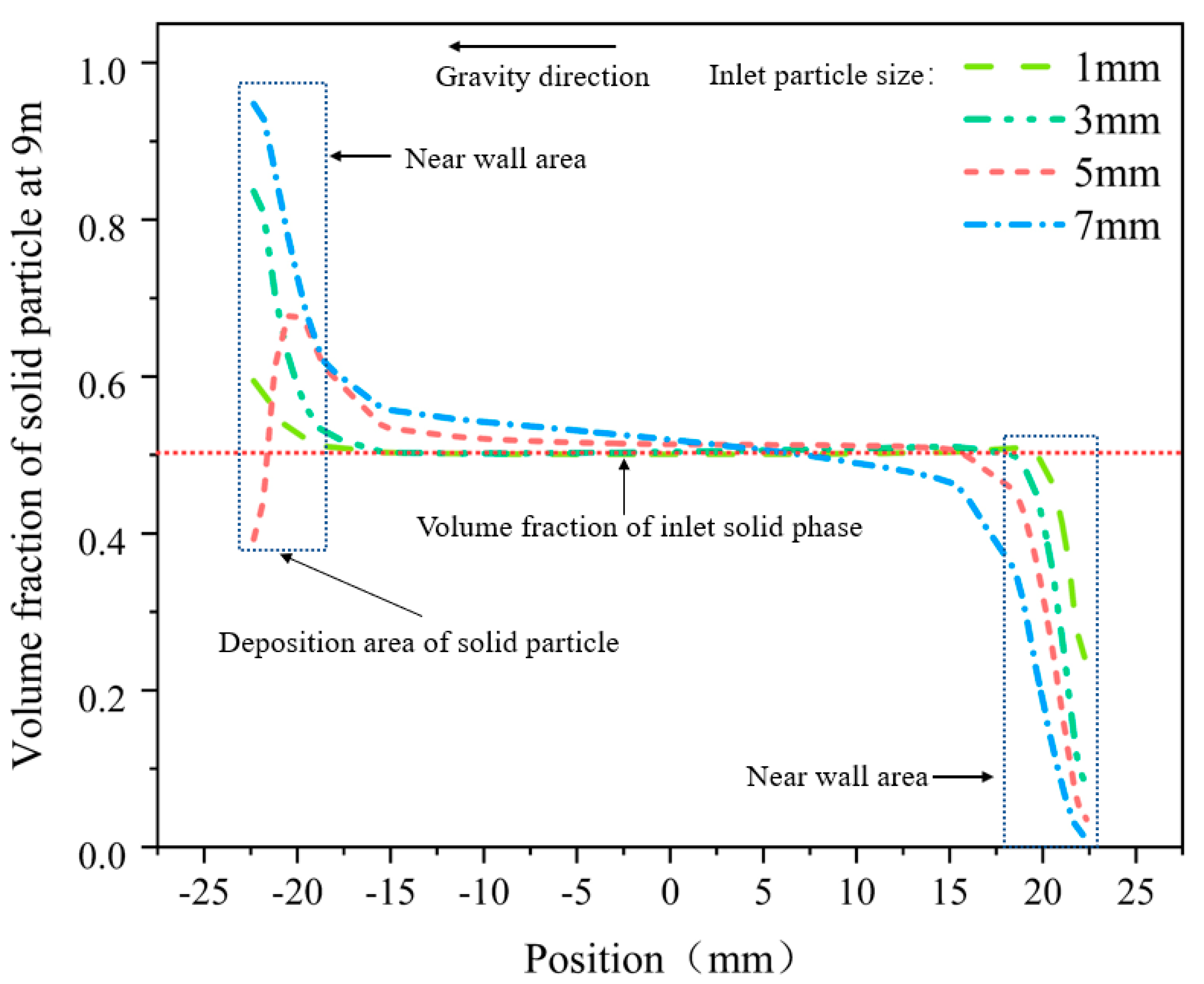
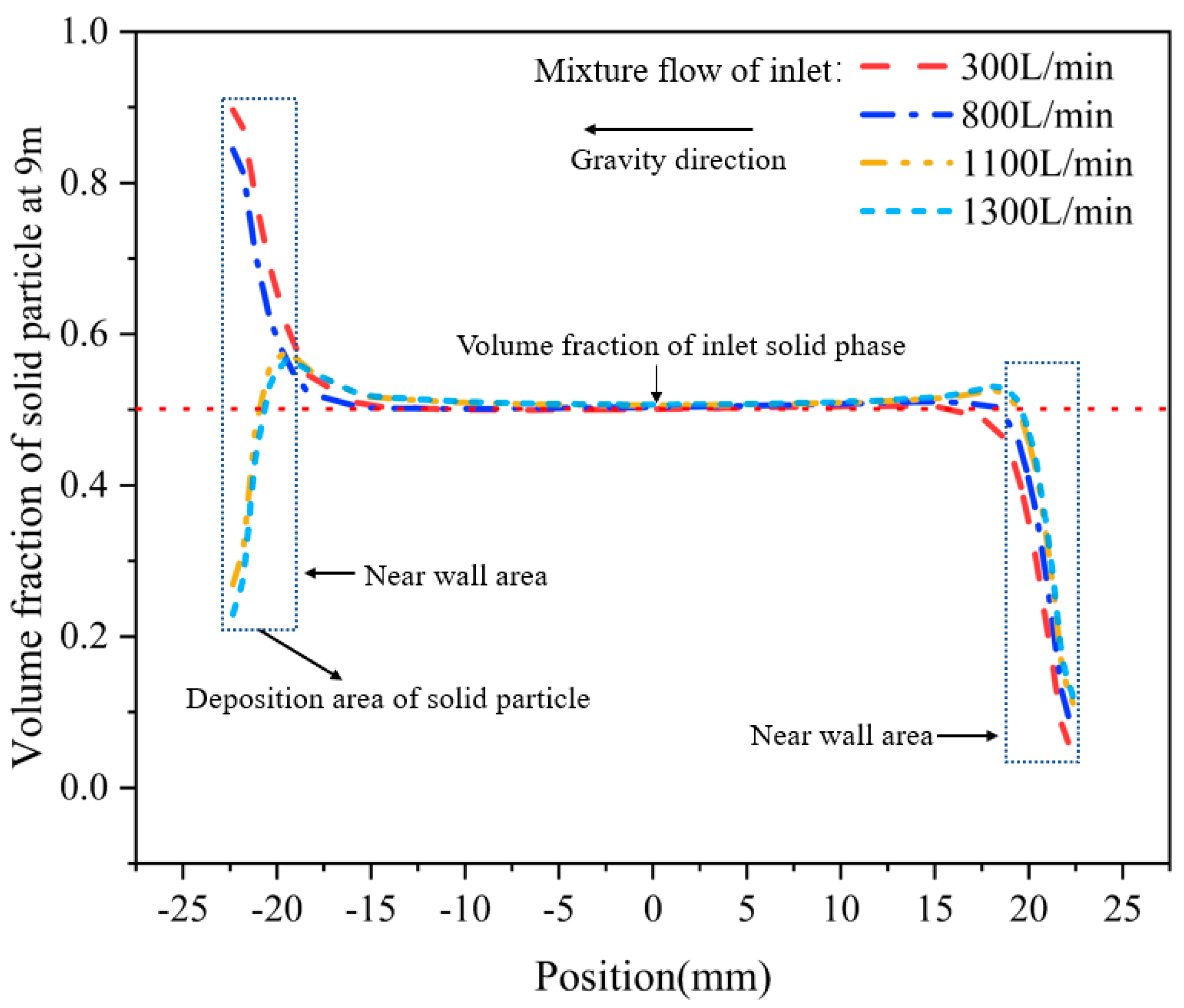
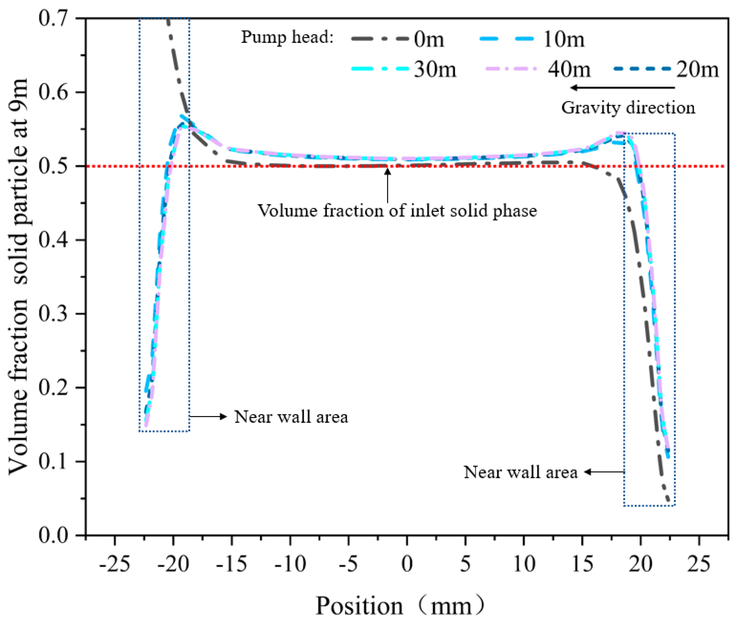
5.1. Analysis of the Efficiency of the DDG Method under Different Working Conditions

From Figure 8, Figure 9, Figure 10 and Figure 11, the migration law of the multiphase mixed slurry of sediment and NGH in the horizontal section of DDG method is analyzed. This study mainly analyses the influence of inlet flow, particle size, volume fraction of the solid particles and head of the lift pump on the migration process of the multiphase mixed slurry of sediment and NGH in the horizontal section.
As shown in Figure 8, when the inlet volume fraction is 0.5, the solid particle deposition at the bottom of the migration channel will also change with the increase of the inlet NGH abundance. When the NGH abundance is 0.2, the NGH content in the multiphase mixed slurry of sediment and NGH at the inlet is less, and the corresponding density of the mixture is relatively large. Therefore, under the same conditions, when the NGH abundance is 0.2, the deposition of solid particles in the migration channel is relatively serious. When the NGH abundance is 0.8, the mixture density is relatively small. Therefore, there is almost no deposition of solid particles at the bottom of the migration channel, which is mainly distributed in the central area and the upper area of the migration channel.
As shown in Figure 9, when the inlet volume fraction is 0.5 and the flow rate is 8.46 m/s, the solid particles in the central area of the migration channel and the upper wall area are mainly suspended. However, in the area near the lower wall, the solid particles deposited in different degrees, and the main migration mode is saltation. With the increase of solid particle size, the deposition rate of solid particles on the wall increases under the migration channel. When the particle size of solid phase is one millimeter, the maximum volume fraction of solid phase near the wall is 0.6, and the deposition amount is relatively small. When the particle size reaches seven millimeters, the maximum volume fraction of solid phase in the area near the wall of the lower wall can reach 0.96, and a large number of solid particles are deposited on the lower wall.
As shown in Figure 10, when the inlet volume fraction is 0.5, the deposition of solid particles will change with the increase of the flow rate of the multiphase mixed slurry of sediment and NGH. When the mixture flow rate is 300 L/min and 800 L/min, the deposition on the wall is serious under the migration channel, and the maximum volume fraction of solid particles can reach 0.9. When the mixture flow rate is 1100 L/min and 1300 L/min, the solid particles are mainly distributed in the central area of the migration channel, and there is almost no deposition on the wall under the migration channel.
As shown in Figure 11, when the solid particle volume fraction at the inlet is 0.5, the flow rate is 6.35 m/s and there is no lift pump, the volume fraction in the central area of the migration channel is 0.5. The volume fraction of solid particles is less than 0.5 in the area near the wall on the upper part of the transport channel and 0.7 in the area near the wall on the lower part of the transport channel, which is much higher than 0.5 in the area near the entrance. Therefore, the solid particles are deposited on the lower wall, while in the center of the migration channel, the solid particles are mainly suspended in the drilling fluid to move forward. When the lift pump acts on the transport channel, the volume fraction near the wall of the transport channel is less than 0.5. Therefore, it can be considered that the solid-free particles are deposited in the wall area under the migration channel.
From the above analysis results, it can be seen that in the DDG method, the migration process of NGH solid-phase particles in the horizontal section is closely related to NGH abundance, solid-phase particle size, drilling fluid flow and whether there is lift pump. In the same case, the higher the NGH abundance is, the lower the deposition rate is. The larger the flow rate of drilling fluid is, the lower the deposition rate in the migration channel is. The smaller the solid particle diameter is, the higher the migration efficiency is. The transport efficiency of solid particles with lift pump is higher than that without lift pump.

5.2. Comparative Analysis of Different Methods of Transport Efficiency under the Same Working Conditions

In view of the migration rule of the multiphase mixed slurry of sediment and NGH in the horizontal section of the DDG method, the migration efficiency of the multiphase mixed slurry of sediment and NGH under the conditions of the same flow rate, the same particle size and the same flow rate is selected and compared with the traditional drilling method.
As shown in Figure 12, when the flow rate of drilling fluid is 300 L/min, due to the large diameter of NGH particles produced after breaking, under the migration channel of traditional drilling method, the annulus is almost solid-phase particle deposits. For the DDG method, under the same circumstances, only a small number of solid particles are deposited near the lower wall of the migration channel, and the solid particles are mainly distributed in the middle and upper regions of the migration channel.
As shown in Figure 13, in the case of the same particle size of one millimeter and the same drilling fluid flow rate, the solid particles in the wall area near the wall surface of the traditional method are seriously deposited by the influence of gravity. The maximum sediment volume fraction can reach 0.9. For the double-layer continuous-pipe double-gradient drilling method, under the same circumstances, the deposition of solid particles on the lower wall of the migration channel is relatively small, and the maximum volume fraction is 0.6.
As shown in Figure 14, at the same flow rate, although the volume fractions of the two methods are relatively close at the lower wall surface, the thickness of the solid phase particles deposited by the conventional drilling method is significantly higher than that of the DDG method. When the double-layer continuous pipe has the function of a lift pump, the solid particles will be in a suspended state inside the migration channel and will not be deposited on the bottom of the migration channel to form a rock debris bed. In addition, because the migration channel of the conventional drilling method is the annulus formed by the drill string and the well wall and the NGH formation is relatively soft, the flow velocity in the annulus cannot be too high or it will cause accidents such as collapse of the well wall. Since the multiphase mixed slurry of sediment and NGH in the DDG method migrations in the double-layer continuous pipe, its flow rate will not be limited, which will be more conducive to the migration of NGH particles.

6. Conclusions

Based on the existing problems in the operation of NGH SSFM, a new drilling and production method of NGH named DDG is proposed. A numeric simulation method was used to analyze the migration efficiency of the multiphase mixed slurry of sediment and NGH in the horizontal section, and the results are compared with the traditional drilling method under the same conditions. The results are as follows:
  • The greater the NGH abundance, the lower the deposition rate inside the migration channel. When the NGH abundance is 0.8, no sediment will appear at the bottom of the migration channel. The greater the flow rate of drilling fluid, the lower the deposition rate inside the migration channel. When the mixture flow rate is 800 L/min, the migration channel still has sedimentation. When the flow rate reaches 1100 L/min, solid particles are mainly distributed in the upper and middle part of the migration channel, and almost no solid particles are deposited at the bottom of the channel. In addition, the smaller the diameter of the solid particles, the higher the migration efficiency. When there is a lift pump, the migration efficiency of solid particles is higher than that without a lift pump.
  • Under the same conditions, the migration efficiency of the multiphase mixed slurry of sediment and NGH inside the DDG method is higher than that of the traditional drilling method. The advantages of the DDG method are more obvious when there is a lifting pump. In addition, since the multiphase mixed slurry of sediment and NGH in the DDG method migrations in the double-layer continuous pipe, its flow rate will not be limited, which will be more conducive to the migration of NGH particles.

Author Contributions

Conceptualization, G.W.; Data curation, Y.H.; Software, P.S.; Supervision, Y.T.; Writing–original draft, J.Y. All authors have read and agreed to the published version of the manuscript.

Funding

This work was supported by National Key R&D Program of China (No. 2018YFC0310201 and 2018YFC0310205), Sichuan Science and Technology Program (2020YJ0152), Postdoctoral Innovative Talent Support Program Project (No. BX20190292), Sichuan Science and Technology Innovation (Seedling Project) Cultivation and Small Invention Small Creation Project (No. 2019090), the Funded of Southern Marine Science and Engineering Guangdong Laboratory (Zhanjiang) (No. ZJW-2019–03), Open Fund (PLN201827) of State Key Laboratory of 0il and Gas Reservoir Geology and Exploitation (Southwest Petroleum University).

Conflicts of Interest

The authors declare that there is no conflicts of interests regarding the publication of this study.

Nomenclature

NGHNatural gas hydrate
SSFMSolid-state fluidized mining
DDGDouble-layer continuous-pipe double-gradient drilling
D R Thickness of NGH formation
L H Radius of NGH formation
ρ s Density of seawater
ρ i Density of isolation fluid
ρ Density of drilling fluid
h s Height of seawater
h i Height of isolation fluid
h m Respective height of drilling fluid
P b Bottom pressure of the well bore
g Acceleration of gravity
Δ P w i n d o w Safety differential pressure window of formation pressure
P f Formation fracture pressure
P L e a k Formation loss pressure
P p r o Formation pore pressure
P c p Formation collapse pressure
P b 1 Pressure value after the bottom pressure of the well bore is reduced
Δ h 1 Reduced height of the drilling fluid hydrostatic column
P b 2 Pressure value after the bottom pressure of the well bore increases
Δ h 2 Increased height of the hydrostatic column
Q 1 Flow rate of drilling fluid flowing from the outer pipe of the double-layer continuous pipe in a balanced state
Q 2 Flow rate returning from the inner tube of the double-layer continuous tube under equilibrium
Δ q 1 The increase of the flow rate returned from the inner tube of the double-layer continuous tube after adjusting the speed of the lift pump
Q 2 the flow rate returned from the inner tube of the double-layer continuous tube in condition 1
Q 2 Reduction of the flow rate returned from the inner tube of the double-layer continuous tube after adjusting the speed of the lift pump.
Δ q 2 the flow rate returned from the inner tube of the double-layer continuous tube in condition 2
d p Particle size of the solid phase
ρ s Density of the solid phase particles
ρ l Drilling fluid density
C D Drag coefficient
C L Lift coefficient
d Constant related to d p
a D Constant coefficient
a L Constant coefficient
v Instantaneous flow velocity acting on the particles
a c Constant coefficient
γ o Dry bulk density of the particles
γ o + Stable dry bulk density of the particles
ε Bonding force parameter, for natural sand, generally take 1.75 × 10⁻⁶ m3/s2
F d p Pressure gradient
k Turbulent kinetic energy
ε Turbulent dissipation rate
μ Dynamic viscosity coefficient
μ t Residual viscosity
u i Average speed
μ e f f Coefficient of kinematic viscosity
G k Term generated by the residual kinetic energy k
G b Generation term of turbulent kinetic energy k caused by buoyancy
Y M Influence of the wave expansion of the compressible turbulence
α k Turbulent Prandtl number of k
α ε Turbulent Prandtl number of ε
S k User-defined source item
S ε User-defined source item
τ l ¯ ¯ Pressure and strain tensor of drilling fluid
τ s ¯ ¯ Pressure and strain tensor of solid particles
F l External volume force of drilling fluid
F l i f t , l Lifting force
F v m , l Virtual quality force
m ˙ s l and m ˙ l s Mass transferred between solid particles and drilling fluid
u s l and u l s Interphase velocity of drilling fluid and solid particles
K s l and K l s Momentum exchange coefficient between drilling fluid and solid particles

References

  1. Wang, J.; Li, J.; Liu, G.; Huang, T.; Yang, H. Parameters optimization in deep-Water dual-Gradient drilling based on downhole separation. J. Pet. Explor. Dev. 2019, 46, 819–825. [Google Scholar] [CrossRef]
  2. Zhou, J.; Nygaard, G. Automatic model-Based control scheme for stabilizing pressure during dual-Gradient drilling. J. Process. Control. 2011, 21, 1138–1147. [Google Scholar] [CrossRef]
  3. Wang, X.-R.; Sun, B.; Luo, P.-Y.; Wang, Z.; Wang, N.; Ke, K.; Zhang, H. Transient temperature and pressure calculation model of a wellbore for dual gradient drilling. J. Hydrodyn. 2018, 165–178. [Google Scholar] [CrossRef]
  4. Chong, Z.R.; Yang, S.H.B.; Babu, P.; Linga, P.; Li, X.-S. Review of natural gas hydrates as an energy resource: Prospects and challenges. Appl. Energy 2016, 162, 1633–1652. [Google Scholar] [CrossRef]
  5. Gao, Y.; Yang, M.; Zheng, J.-N.; Chen, B. Production characteristics of two class water-Excess methane hydrate deposits during depressurization. J. Fuel. 2018, 232, 99–107. [Google Scholar] [CrossRef]
  6. Tang, Y.; Wang, G.; Zhou, S.; Liu, Q.; Zhong, L.; Li, W.; Li, Q.; Fu, Q.; He, Y.; Wang, C.; et al. Solid Fluidization Green Mining Apparatus and Method for Shallow-Layer Natural Gas Hydrates in Seabed. PCT /085796, 7 May 2018. [Google Scholar]
  7. Zhou, S.; Chen, W.; Li, Q.; Zhou, J.; Shi, H. Research on the solid fluidization well testing and production for shallow non-Diagenetic natural gas hydrate in deep water area. J. Offshore Oil Gas. China 2017, 29, 1–8. [Google Scholar]
  8. Zhou, S.; Chen, W.; Li, Q. Solid state fluidized green mining technology for deep water shallow gas hydrate. J. China Offshore Oil Gas. 2014, 5, 1–7. [Google Scholar]
  9. Khatibi, M.; Time, R.W.; Shaibu, R. Dynamical feature of particle dunes in Newtonian and shear-thinning flows: Relevance to hole-Cleaning in pipe and annulus. Int. J. Multiph. Flow 2018, 99, 284–293. [Google Scholar] [CrossRef]
  10. Sorgun, M.; Aydin, I.; Ozbayoglu, M.E. Friction factors for hydraulic calculations considering presence of cuttings and pipe rotation in horizontal/highly-Inclined wellbores. J. Pet. Sci. Eng. 2011, 78, 407–414. [Google Scholar] [CrossRef]
  11. Zouaoui, S.; Djebouri, H.; Mohammedi, K.; Khelladi, S.; Aider, A.A. Experimental study on the effects of big particles physical characteristics on the hydraulic transport inside a horizontal pipe. Chin. J. Chem. Eng. 2016, 24, 317–322. [Google Scholar] [CrossRef] [Green Version]
  12. Zhu, X.; Li, J.; Tong, H. Mechanism analysis and process optimization of sand and plug removal with rotating jet in horizontal well. J. Cent. South Univ. 2013, 20, 1631–1637. [Google Scholar] [CrossRef]
  13. Tang, Y.; Yao, J.; He, Y.; Sun, P.; Jin, X. Study on pressure—Controlled sliding sleeve of jet breaking for natural gas hydrate mining based on throttle pressure drop principle. Energy Sci. Eng. 2020, 8, 1422–1437. [Google Scholar] [CrossRef]
  14. Wei, N.; Sun, W.; Meng, Y.; Liu, A.; Zhao, J.; Zhou, S.; Zhang, L.; Li, Q. Multiphase non equilibrium pipe flow behaviors in the solid fluidization exploitation of marine natural gas hydrate reservoir. Energy Sci. Eng. 2018, 6, 760–782. [Google Scholar] [CrossRef] [Green Version]
  15. Werner, B.; Myrseth, V.; Saasen, A. Viscoelastic properties of drilling fluids and their influence on cuttings transport. J. Pet. Sci. Eng. 2017, 156, 845–851. [Google Scholar] [CrossRef]
  16. Zhu, X.; Shen, K.; Li, B.; Lv, Y. Cuttings Transport Using Pulsed Drilling Fluid in the Horizontal Section of the Slim-Hole: An Experimental and Numerical Simulation Study. Energies 2019, 12, 3939. [Google Scholar] [CrossRef] [Green Version]
  17. Hakim, H.; Katende, A.; Sagala, F.; Ismail, I.; Nsamba, H. Performance of polyethylene and polypropylene beads towards drill cuttings transportation in horizontal wellbore. J. Pet. Sci. Eng. 2018, 165, 962–969. [Google Scholar] [CrossRef]
  18. Ofei, T.N.; Yaaqob, S.Y. Numerical simulation of transport behaviour of small cuttings in extended reach wells. J. Int. J. Oil Gas Coal Technol. 2019, 21, 149–168. [Google Scholar] [CrossRef]
  19. Wei, N.; Xu, H.; Sun, W.; Zhao, J.; Zhang, L.; Fu, Q.; Pang, W.; Zheng, L.; Lü, X. Migration laws of natural gas hydrate solid particles with different abundance in horizontal wells. J. Nat. Gas Ind. 2017, 037, 75–80. [Google Scholar] [CrossRef]
  20. Fu, Q.; Wei, N.; Meng, Y.; Sun, W.; Guo, P. Mode of wellbore multiphase flow and its sensitivity analysis during drilling in deep water natural gas hydrate reservoirs. J. China Offshore Oil Gas 2016, 4, 107–113. [Google Scholar]
  21. Heydari, O.; Sahraei, E.; Skalle, P. Investigating the impact of drillpipe’s rotation and eccentricity on cuttings transport phenomenon in various horizontal annuluses using computational fluid dynamics (CFD). J. Pet. Sci. Eng. 2017, 156, 801–813. [Google Scholar] [CrossRef]
  22. Pang, B.; Wang, S.; Jiang, X.; Lu, H. Effect of orbital motion of drill pipe on the transport of non-Newtonian fluid-cuttings mixture in horizontal drilling annulus. J. Pet. Sci. Eng. 2019, 174, 201–215. [Google Scholar] [CrossRef]
  23. Sultan, R.A.; Rahman, M.A.; Rushd, S.; Zendehboudi, S.; Kelessidis, V.C. Validation of CFD model of multiphase flow through pipeline and annular geometries. Part. Sci. Technol. 2018, 37, 685–697. [Google Scholar] [CrossRef]
  24. Argyropoulos, C.; Markatos, N.C. Recent advances on the numerical modelling of turbulent flows. Appl. Math. Model. 2015, 39, 693–732. [Google Scholar] [CrossRef]
  25. Chen, X.; Wheeler, C. Computational Fluid Dynamics (CFD) modelling of transfer chutes: Assessment of viscosity, drag and turbulence models. Int. J. Multiph. Flow 2015, 69, 42–53. [Google Scholar] [CrossRef]
  26. Zhang, Y.; Wang, X.; Hu, H.; Kang, S. Effect of turbulence model on CFD simulation of turbulent jet. J. Propuls. Technol. 2016, 6, 1049–1054. [Google Scholar]
  27. Li, Y.; He, W. Engineering Fluid Mechanics; Tsinghua University Press: Beijing, China, 2006; pp. 187–196. [Google Scholar]
  28. Siswantara, A.I.; Darmawan, S.; Tanujaya, H. Inverse-Turbulent Prandtl Number Effects on Reynolds Numbers of RNG k-ε Turbulence Model on Cylindrical-Curved Pipe. Appl. Mech. Mater. 2015, 758, 35–44. [Google Scholar]
  29. Sorgun, M.; Muftuoglu, T.D.; Ulker, E. Fuzzy logic modelling of liquid-Solid two-phase flow in horizontal and inclined wellbores. J. Int. J. Oil Gas Coal Technol. 2018, 19, 438–448. [Google Scholar] [CrossRef]
Figure 1. DDG method.
Energies 13 03792 g001
Figure 2. Double-layer continuous-pipe double-gradient drilling (DDG) method normal model.
Energies 13 03792 g002
Figure 3. Types of solid particle migration.
Energies 13 03792 g003
Figure 4. Schematic diagram of horizontal section movement of DDG method.
Energies 13 03792 g004
Figure 5. Schematic diagram of slurry movement in horizontal section of traditional method.
Energies 13 03792 g005
Figure 6. Schematic diagram of particle force analysis.
Energies 13 03792 g006
Figure 7. Schematic diagram of the numeric-simulation physical model.
Energies 13 03792 g007
Figure 8. Effect of natural gas hydrate (NGH) abundance changes on the migration process of solid particles.
Energies 13 03792 g008
Figure 9. Effect of solid particle size change on the migration process.
Energies 13 03792 g009
Figure 10. Effect of flow rate of the multiphase mixed slurry of sediment and NGH on the migration.
Energies 13 03792 g010
Figure 11. Effect of lift head change on solid particle migration process.
Energies 13 03792 g011
Figure 12. Comparison of two methods of migration under the same flow rate.
Energies 13 03792 g012
Figure 13. Comparison of migration between the two methods under the same particle size.
Energies 13 03792 g013
Figure 14. Comparison of migration between the two methods at the same flow rate.
Energies 13 03792 g014
Table 1. Main tools and functions of drilling and production tool string.
NumberNameFunction
1NGH drill bitHorizontal collar drilling
2Pressure controlled sliding sleeveControl the opening and closing of the jet nozzles
3Turbo motorProvide power for drill bit and lift pump
4Subsea lift pumpControl the pressure of wellbore to improve the efficiency of solid particle migration
5Test toolMonitor and collect data of wellbore
6Bridge channelUsed for the interaction of the flow channel between the inner and outer tubes of the double-layer continuous pipe
Table 2. Two methods of horizontal-channel migration channel size.
NumberDDG MethodValueTraditional MethodValue
1Outer diameter of migration channel D s o 50.8 mmWellbore diameter D c z 241.3 mm
2Inner diameter of migration channel D s i 44.8 mmColumn diameter D c h 127 mm
3Numeric simulation model length10 mNumeric simulation model length10 m

