Article

General Formula for SHE Problem Solution

by
Concettina Buccella
*,†,
Maria Gabriella Cimoroni
and
Carlo Cecati
Department of Information Engineering, University of L’Aquila, Computer Science and Mathematics and DigiPower srl, 67100 L’Aquila, Italy
*
Author to whom correspondence should be addressed.
These authors equally contributed to this work.
Energies 2020, 13(14), 3740; https://doi.org/10.3390/en13143740
Submission received: 25 May 2020 / Revised: 3 July 2020 / Accepted: 9 July 2020 / Published: 20 July 2020
(This article belongs to the Special Issue Multilevel Power Converters Control and Modulation Techniques)

Abstract

:
This paper considers cascaded H-bridges multilevel inverters with 2 n dc sources, n integer, n > 0 and proposes a new general formula to compute those 2 n switching angles capable of eliminating n + 1 harmonics and their respective multiples from the output voltage waveform. The proposed procedure uses only scalar products and avoids linear systems, therefore it has a low computational cost. Computed angles do not depend on modulation index, moreover, voltage sources vary linearly. A mathematical proof is given to validate the formula. Three-phase implementations eliminate or mitigate a significant amount of low order harmonics, thus resulting in very low total harmonic distortion. The proposed formula has been experimentally validated using a single-phase nine-level cascaded H-bridge inverter prototype, resulting in a Total Harmonic Distortion (THD) of 5.59%; the first not-mitigated harmonic is the 17th.

Graphical Abstract

1. Introduction

Due to their low Total Harmonic Distortion (THD), low electromagnetic interference, and high efficiency, the use of multilevel inverters (MLI) is expanding in many applications [1,2,3]. Cascaded H-bridge (CHB) topology, in particular, is receiving more attention than neutral point clamped (NPC) and flying capacitor (FC) topologies because it offers modularity and better overall operations [4,5,6].
Operations at fundamental frequency greatly improve efficiency, therefore they are preferred at high power. The main approaches for selection of switching angles at a modulation of low frequency are: (i) THD minimization and (ii) Selective Harmonics Elimination (SHE) [7,8]. The first one can be achieved using either frequency or time domain algorithms. SHE consists in elimination of a number of harmonics imposing their magnitudes to zero, depending on degrees of freedom and consequently on applied switching frequency [9].
SHE Pulse Width Modulation (SHE-PWM) strategies have been introduced to improve dynamic performances in conventional SHE, thus resulting in the advantages of both techniques. In order to further improve THD, Selective Harmonic Mitigation Pulse Width Modulation (SHM-PWM) has been introduced, obtaining a high number of reduced harmonics capable of bounding harmonics content within grid standards allowing the connection of the power converter with the public grid [10].
The SHE and SHM problems are based on the solution of nonlinear transcendental equations or inequalities [11,12]. In this regard, stochastic optimization techniques have been presented in the literature, such as genetic algorithms (GA) [13], bee algorithms (BA) [14], cuckoo search algorithms (CSA) [15] and particle swarm optimization (PSO) [16,17,18].
In [19], a modified version of the fish swarm optimization algorithm has been examined for computing optimum switching angles required to control the switched-diode dual source single switch MLI. Suitability and superiority of the derived algorithm have been established by comparison with traditional SHE techniques. Analytical methods have been proposed for five level inverters in [20] and for multilevel inverters in [21], which are based on a novel pulse amplitude modulation (PAM) strategy. In [22], a method was introduced as a substitute for the Newton–Raphson method and similar iteration methods that can perform a real-time calculation of switching angles in seven level inverters.
In [23], CHB l-level inverters, l = 2 s + 1 , with s = 2 n , n integer, n > 0 have been considered and a linear system 2 n × 2 n has been proposed to find switching angles. In this paper, the same topologies are considered and a simple mathematical formula consisting of s scalar products by two vectors returning s switching angles is proposed, which require lower computational cost than that obtained by the procedure in [23]. These angles allow to eliminate n + 1 harmonics and their respective multiple from the output voltage waveform and do not depend on modulation index m. Typical applications of the proposed method are uninterruptible power supplies (UPS), high voltage dc (HVDC) and aircrafts.
Section 2 describes the mathematical formula for computation of the switching angles, the related procedure, its mathematical proof and computational cost. Section 3 presents simulation results and comparisons with the procedure in [21]. Section 4 reports and discusses experimental validation. Section 5 draws some conclusions and remarks.

2. Mathematical Formulation

2.1. Mathematical Model

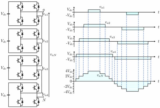
The proposed SHE strategy computes s = 2 n switching angles that eliminate n + 1 harmonics and their multiple from the output voltage of an l-level CHB inverter with s dc sources, n = 1 , 2 , 3 , and l = 2 s + 1 . Each H-bridge is fed by a dc voltage source in which the amplitude is V 1 = V 2 = = V s = V and, in per unit (p.u.): V * = V V d c being V d c the rated voltage. Figure 1 shows a three-phase CHB l-level inverter.
Considering the phase A output voltage v A N , its Fourier decomposition is
v A N ω t = k = 1 , 3 , 5 , . . . H k sin k ω t
where H k = 4 π k i = 1 s V * cos k α i is the kth harmonic. The following SHE system is considered
cos k α 1 + cos k α 2 + + cos k α s = 0 , k = r 1 , r 2 , , r n + 1
where r i , i = 1 , 2 , , n + 1 are the n + 1 harmonics to delete, which can be arbitrarily chosen; for single-phase configurations r 1 = 3 , r 2 = 5 and so on; instead, for three-phase configurations, the third and multiple are automatically zero and r 1 = 5 , r 2 = 7 and so on.
The switching angles α 1 , , α s are the unknowns of the problem that have to satisfy the following conditions
0 < α k < π 2 , k = 1 , 2 , 3 , , s
V * is assumed linearly depending on modulation index m = π H 1 4 · s , where H 1 is the fundamental harmonic amplitude of output voltage
V * = C m
with C positive coefficient, computed as
C = s cos α 1 + cos α 2 + . . . cos α s
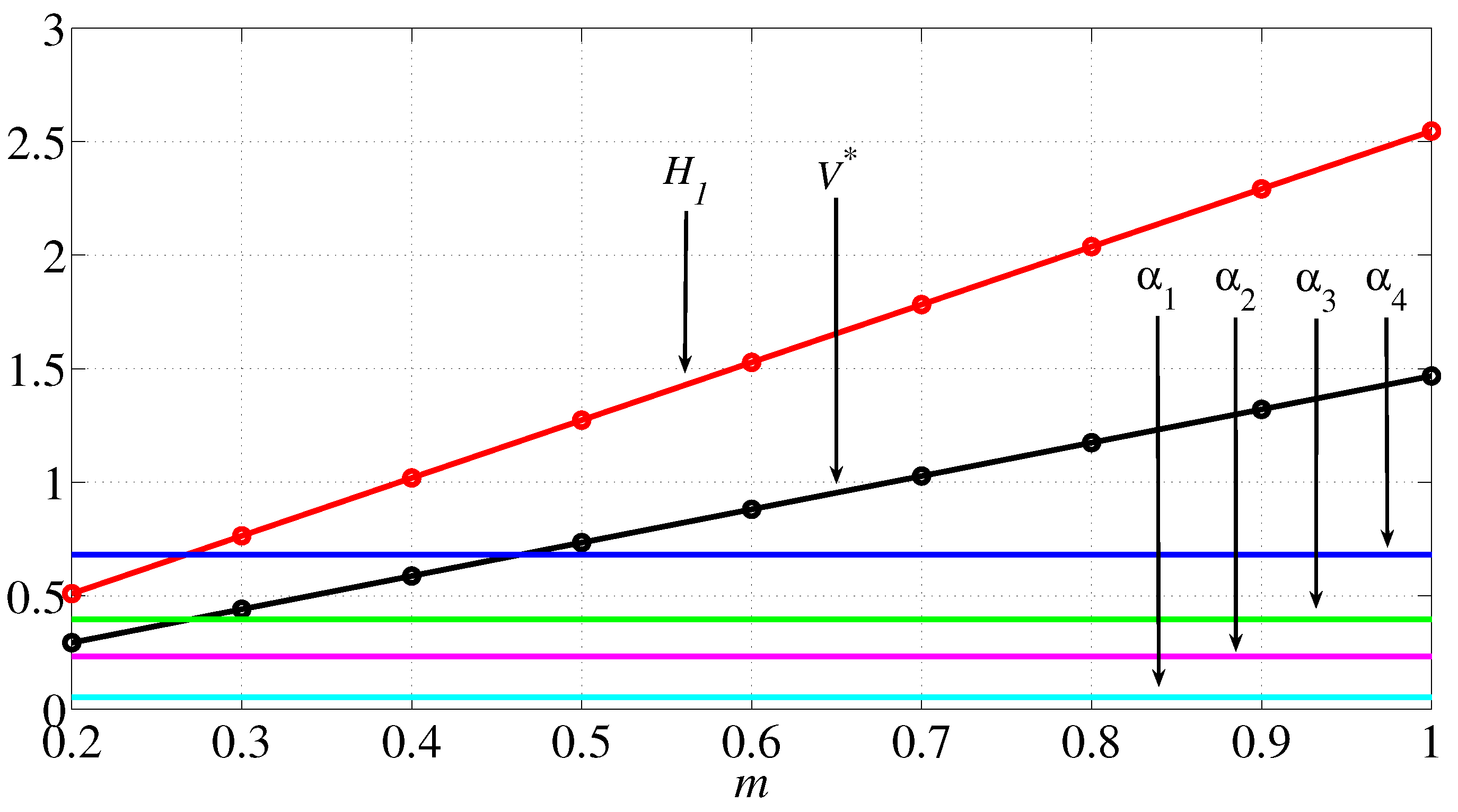
In the next subparagraph, a theorem will be introduced to obtain Formula (7), equivalent to Formula (10), which returns the switching angles that do not depend on the modulation index. Due to this, both the amplitude of the fundamental harmonic and the dc voltage source linearly depend on m. Given a value to m, the following quantities are calculated, in this order: (1) switching angles, (2) parameter C, (3) dc voltage source V * = C m , (4) H 1 = 4 s m π = 4 s V * π C . Figure 2 and Figure 3 show the behaviors of switching angles, dc voltage source and fundamental harmonic, as a function of m, for single-phase five-level and three-phase nine-level configurations, respectively.

2.2. Fast Algorithm to Obtain the General Formula

The proposed algorithm computes s = 2 n , n > 0 switching angles through s scalar products between vectors of size n + 1 . To achieve the goal, the following theorem is introduced.
Theorem 1.
Let s = 2 n with n integer, n > 0 ; the system
cos k α 1 + cos k α 2 + + cos k α s = 0 , k = r 1 , r 2 , , r n + 1
is considered in the unknowns α i , i = 1 , , s with r j odd integer number, j = 1 , , n + 1 , r j 3 .
Then a solution of (6) is
α = π 2 j = 1 n + 1 1 w 1 j 1 r j , j = 1 n + 1 1 w 2 j 1 r j , , j = 1 n + 1 1 w s j 1 r j T
where w i j , i = 1 , , s , j = 1 , , n + 1 are the elements of the matrix W s × n + 1 in which theith row represents the integer number i 1 in a binary base with n + 1 digits.
This solution satisfies also
cos k α 1 + cos k α 2 + + cos k α s = 0 , k = q r 1 , q r 2 , , q r n + 1 , q > 1 , odd number
Proof. 
In [23], the system (6) has been transformed in the following s × s linear system in the unknown α = α 1 , α 2 , , α s T that satisfies (6) and (8)
A α = b
For instance, if n = 4 , the system matrix A 16 × 16 was
A 2 4 × 2 4 = S 1 O O O O O O O O S 1 O O O O O O O O S 1 O O O O O O O O S 1 O O O O O O O O S 1 O O O O O O O O S 1 O O O O O O O O S 1 O O O O O O O O S 1 S 2 S 2 O O O O O O O O S 2 S 2 O O O O O O O O S 2 S 2 O O O O O O O O S 2 S 2 S 2 S 2 S 2 S 2 O O O O O O O O S 2 S 2 S 2 S 2 S 2 S 2 S 2 S 2 S 2 S 2 S 2 S 2 S 2 S 2 S 2 S 2 S 2 S 2 S 2 S 2
where S 1 = [ 1 1], S 2 = [ 1 −1], O = [ 0 0]. The vector b in (9) was
b 2 4 × 1 = π r 1 , , π r 1 2 4 1 , 2 π r 2 , , 2 π r 2 2 4 2 , 2 2 π r 3 , , 2 2 π r 3 , 2 4 3 2 4 1 π r 4 2 0 , 2 4 1 π r 4 + 1 2 0 T
The switching angles in [23] have been obtained by solving (9)) through LU factorization of A. For this proof, introducing the matrix G 2 n × 2 n that, for the considered example ( n = 4 ), is defined as
G 2 4 × 2 4 = 1 2 S 1 O O O O O O O O 1 2 S 1 O O O O O O O O 1 2 S 1 O O O O O O O O 1 2 S 1 O O O O O O O O 1 2 S 1 O O O O O O O O 1 2 S 1 O O O O O O O O 1 2 S 1 O O O O O O O O 1 2 S 1 1 2 2 S 2 1 2 2 S 2 O O O O O O O O 1 2 2 S 2 1 2 2 S 2 O O O O O O O O 1 2 2 S 2 1 2 2 S 2 O O O O O O O O 1 2 2 S 2 1 2 2 S 2 1 2 3 S 2 1 2 3 S 2 1 2 3 S 2 1 2 3 S 2 O O O O O O O O 1 2 3 S 2 1 2 3 S 2 1 2 3 S 2 1 2 3 S 2 1 2 4 S 2 1 2 4 S 2 1 2 4 S 2 1 2 4 S 2 1 2 4 S 2 1 2 4 S 2 1 2 4 S 2 1 2 4 S 2 1 2 4 S 2 1 2 4 S 2 1 2 4 S 2 1 2 4 S 2 1 2 4 S 2 1 2 4 S 2 1 2 4 S 2 1 2 4 S 2
It is easy to verify that G T A = I , where I is the identity matrix; therefore G T = A 1 and the solution α = G s × s T b s × 1 presents a very easy systematic frame equal to the scalar product Q s × n + 1 u n + 1 × 1
α = Q s × n + 1 u n + 1 × 1
where the vector u = π 2 1 r 1 , 1 r 2 , , 1 r n + 1 T and the matrix Q is
Q = 1 W = 1 w 11 1 w 12 1 w 1 , n + 1 1 w 21 1 w 22 1 w 2 , n + 1 1 w s 1 1 w s 2 1 w s , n + 1 .
The exponents w i j , i = 1 , , s , j = 1 , , n + 1 are the elements of the matrix W s × n + 1 in which the ith row represents the integer number i 1 in the binary base with n + 1 digits. Therefore, the solution of (6) and (8) is
α = π 2 j = 1 n + 1 1 w 1 j 1 r j , j = 1 n + 1 1 w 2 j 1 r j , , j = 1 n + 1 1 w s j 1 r j T
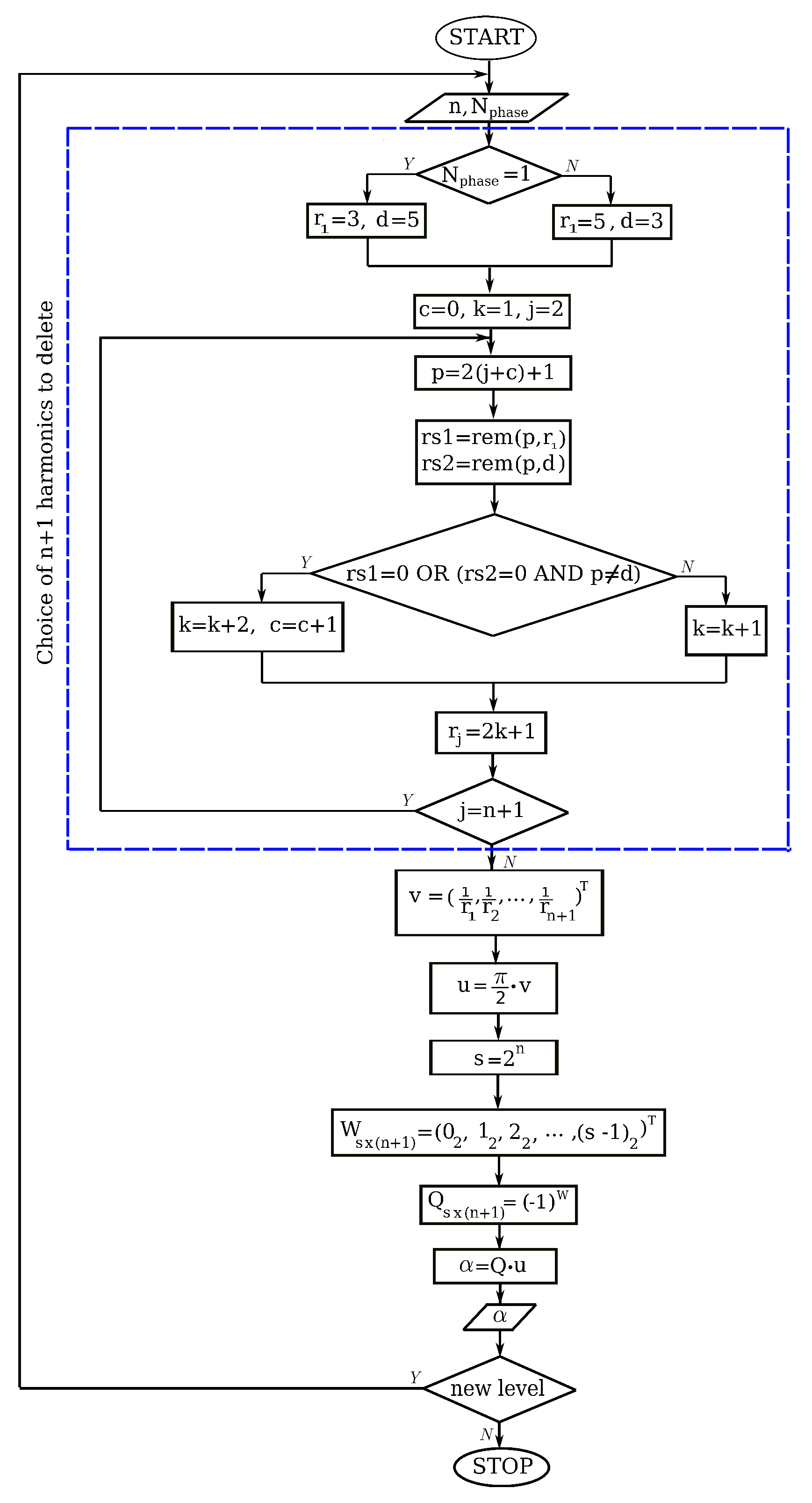
The flow chart of the proposed strategy is shown in Figure 4.
The first part of the flow chart, bounded by a dashed line, represents the preliminary algorithm that, based on single or three-phase system, chooses the first n + 1 harmonics to be deleted. In particular, given the number of phases N p h a s e , the algorithm considers the order of the first harmonic to be deleted, equal to r 1 = 3 if N p h a s e = 1 or r 1 = 5 if N p h a s e 1 (three-phase) and for successive harmonics it jumps the multiple of 3 and 5, because they will be eliminated by the proposed method (see (8)). The harmonics multiple of 7, 11 and greater have not been considered because they referred to very high level inverters; in fact, for example, the odd multiples of 7 are 21, 35, 49 and so on, but as 21 is multiple of 3 and 35 is multiple of 5, they have already been skipped, and 49 is the first multiple after r 1 = 3 , r 2 = 5 , r 3 = 7 , r 4 = 11 , r 5 = 13 , r 6 = 17 , r 7 = 19 , r 8 = 23 , r 9 = 29 , r 10 = 31 , r 11 = 37 , r 12 = 41 , r 13 = 43 , r 14 = 47 that is related to l = 2 · 2 14 + 1 for single-phase configuration and l = 2 · 2 13 + 1 for three-phase configuration.
In the flow chart, the function r e m is used to detect the order of multiple harmonics; in fact r e m ( x , y ) returns the division rest between x and y. Of course if r e m ( x , y ) = 0 then x is multiple of y. The generic row of matrix W, denoted with n u m 2 , represents the number n u m in binary base with n + 1 digits. The generic element of the matrix 1 W is 1 w i j , i = 1 , 2 , , 2 n , j = 1 , 2 , , n + 1 .

2.3. Computational Complexity

The procedure in [23] solves the 2 n × 2 n system (9)) by LU factorization and by solution of two triangular systems, therefore it has computational complexity T s y s
T s y s = O 2 3 n 3 + O 2 2 n
that becomes very high when n grows.
Thee proposed procedure multiplies a matrix of elements ± 1 of size 2 n × n + 1 by a vector of length n + 1 , therefore it has computational complexity T s c
T s c = O n 2 n
that is very low with respect to (11).

3. Results

Simulation results have been obtained considering both single and three-phase l-level CHB inverters with l = 5 , 9 , 17 , 33 connected to an RL load, characterized by R = 48.80 Ω and L = 0.94 mH with V * = 1 per unit (p. u.) and switching frequency equal to 50 Hz. Total harmonic distortion, defined by the following formula, is computed to estimate the quality of output voltage waveforms.
THD = k = 3 , 5 301 H k 2 H 1
For grid connection applications, the CIGRE WG 36–05 and the EN 50160 grid codes [24,25] impose, for each harmonic amplitude H n , the admissible levels l n % = H n / H 1 % . These harmonic levels, given in percentage to the fundamental, are shown in Table 1.
In the following, the matrices W, Q, the vector u and the solution α are given for the considered configurations.

3.1. CHB 5-Level Inverter ( n = 1 )

W 2 × 2 = 0 0 0 1 , Q 2 × 2 = 1 1 1 1 , Single-phase ( r 1 = 3 , r 2 = 5 ): u = π 2 1 3 1 5 and α = π 2 1 3 + 1 5 1 3 1 5 , Three-phase ( r 1 = 5 , r 2 = 7 ): u = π 2 1 5 1 7 and α = π 2 1 5 + 1 7 1 5 1 7 .
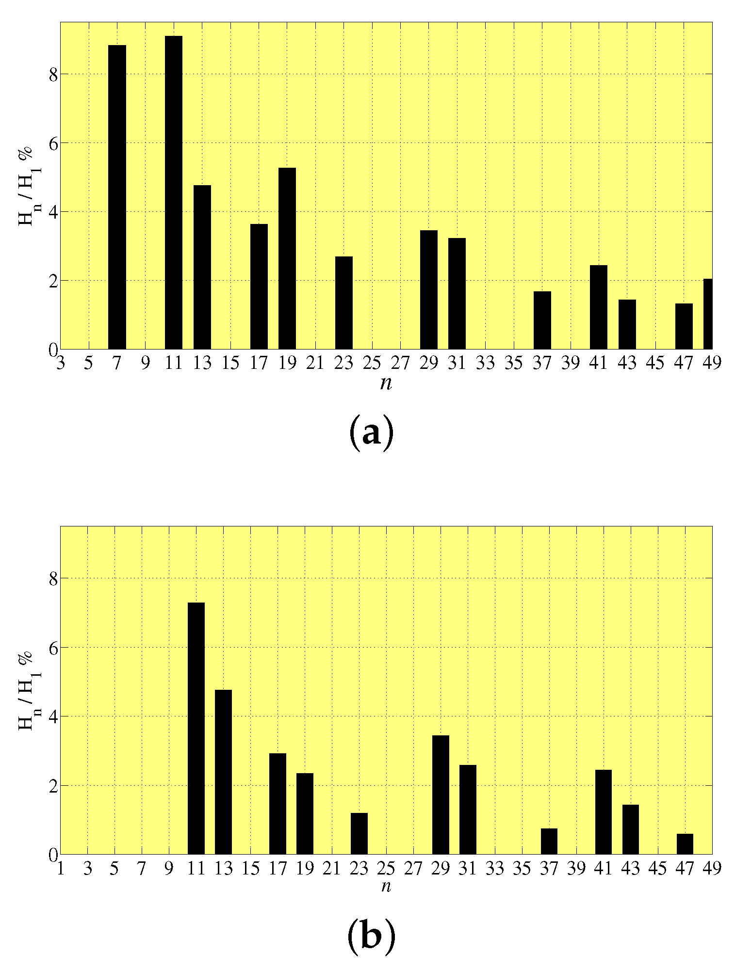
Figure 5 shows the harmonic analysis that is the harmonics amplitude H n with respect to the fundamental H 1 , for single-phase and three-phase configurations. It is possible to observe that the first not eliminated harmonic is the 7th for single-phase configuration and the 11th for the three-phase one.

3.2. CHB 9-Level Inverter ( n = 2 )

W 4 × 3 = 0 0 0 0 0 1 0 1 0 0 1 1 , Q 4 × 3 = 1 1 1 1 1 1 1 1 1 1 1 1 , Single-phase ( r 1 = 3 , r 2 = 5 , r 3 = 7 ): u = π 2 1 3 1 5 1 7 and α = π 2 1 3 + 1 5 + 1 7 1 3 + 1 5 1 7 1 3 1 5 + 1 7 1 3 1 5 1 7 , Three-phase ( r 1 = 5 , r 2 = 7 , r 3 = 11 ): u = π 2 1 5 1 7 1 11 and α = π 2 1 5 + 1 7 + 1 11 1 5 + 1 7 1 11 1 5 1 7 + 1 11 1 5 1 7 1 11 .
The harmonic spectrum of single-phase nine-level inverter is not shown because, from the computed results, it is observed that it coincides with that of three-phase five-level configuration in Figure 5b. Figure 6 shows the harmonic analysis of the three-phase configuration, highlighting that the first five harmonics are eliminated, the 13th is mitigated according to code requirements (see Table 1) and the 15th is deleted [24,25].

3.3. CHB 17-Level Inverter ( n = 3 )

W 8 × 4 = 0 0 0 0 0 0 0 1 0 0 1 0 0 0 1 1 0 1 0 0 0 1 0 1 0 1 1 0 0 1 1 1 , Q 8 × 4 = 1 1 1 1 1 1 1 1 1 1 1 1 1 1 1 1 1 1 1 1 1 1 1 1 1 1 1 1 1 1 1 1 , Single-phase ( r 1 = 3 , r 2 = 5 , r 3 = 7 , r 4 = 11 ): u = π 2 1 3 1 5 1 7 1 11 , α = π 2 1 3 + 1 5 + 1 7 + 1 11 1 3 + 1 5 + 1 7 1 11 1 3 + 1 5 1 7 + 1 11 1 3 + 1 5 1 7 1 11 1 3 1 5 + 1 7 + 1 11 1 3 1 5 + 1 7 1 11 1 3 1 5 1 7 + 1 11 1 3 1 5 1 7 1 11 , Three-phase ( r 1 = 5 , r 2 = 7 , r 3 = 11 , r 4 = 13 ): u = π 2 1 5 1 7 1 11 1 13 , α = π 2 1 5 + 1 7 + 1 11 + 1 13 1 5 + 1 7 + 1 11 1 13 1 5 + 1 7 1 11 + 1 13 1 5 + 1 7 1 11 1 13 1 5 1 7 + 1 11 + 1 13 1 5 1 7 + 1 11 1 13 1 5 1 7 1 11 + 1 13 1 5 1 7 1 11 1 13 .
The obtained results show that the harmonic spectrum of a single-phase 17-level inverter is the same of the three-phase nine-level configuration in Figure 6, and for this reason, this graph is not shown here. Figure 7 shows the harmonic analysis for three phase configuration; the first not mitigated harmonic is the 29th, the previous ones are zero except the 17th, 19th and 23rd, which are mitigated [24,25].

3.4. CHB 33-Level Inverter ( n = 4 )

W 16 × 5 = 0 0 0 0 0 0 0 0 0 1 0 0 0 1 0 0 0 0 1 1 0 0 1 0 0 0 0 1 0 1 0 0 1 1 0 0 0 1 1 1 0 1 0 0 0 0 1 0 0 1 0 1 0 1 0 0 1 0 1 1 0 1 1 0 0 0 1 1 0 1 0 1 1 1 0 0 1 1 1 1 , Q 16 × 5 = 1 1 1 1 1 1 1 1 1 1 1 1 1 1 1 1 1 1 1 1 1 1 1 1 1 1 1 1 1 1 1 1 1 1 1 1 1 1 1 1 1 1 1 1 1 1 1 1 1 1 1 1 1 1 1 1 1 1 1 1 1 1 1 1 1 1 1 1 1 1 1 1 1 1 1 1 1 1 1 1 , Single-phase ( r 1 = 3 , r 2 = 5 , r 3 = 7 , r 4 = 11 , r 4 = 13 ): u = π 2 1 3 1 5 1 7 1 11 1 13 and α = π 2 1 3 + 1 5 + 1 7 + 1 11 + 1 13 1 3 + 1 5 + 1 7 + 1 11 1 13 1 3 + 1 5 + 1 7 1 11 + 1 13 1 3 + 1 5 + 1 7 1 11 1 13 1 3 + 1 5 1 7 + 1 11 + 1 13 1 3 + 1 5 1 7 + 1 11 1 13 1 3 + 1 5 1 7 1 11 + 1 13 1 3 + 1 5 1 7 1 11 1 13 1 3 1 5 + 1 7 + 1 11 + 1 13 1 3 1 5 + 1 7 + 1 11 1 13 1 3 1 5 + 1 7 1 11 + 1 13 1 3 1 5 + 1 7 1 11 1 13 1 3 1 5 1 7 + 1 11 + 1 13 1 3 1 5 1 7 + 1 11 1 13 1 3 1 5 1 7 1 11 + 1 13 1 3 1 5 1 7 1 11 1 13 , Three-phase ( r 1 = 5 , r 2 = 7 , r 3 = 11 , r 4 = 13 , r 4 = 17 ): u = π 2 1 5 1 7 1 11 1 13 1 17 and α = π 2 1 5 + 1 7 + 1 11 + 1 13 + 1 17 1 5 + 1 7 + 1 11 + 1 13 1 17 1 5 + 1 7 + 1 11 1 13 + 1 17 1 5 + 1 7 + 1 11 1 13 1 17 1 5 + 1 7 1 11 + 1 13 + 1 17 1 5 + 1 7 1 11 + 1 13 1 17 1 5 + 1 7 1 11 1 13 + 1 17 1 5 + 1 7 1 11 1 13 1 17 1 5 1 7 + 1 11 + 1 13 + 1 17 1 5 1 7 + 1 11 + 1 13 1 17 1 5 1 7 + 1 11 1 13 + 1 17 1 5 1 7 + 1 11 1 13 1 17 1 5 1 7 1 11 + 1 13 + 1 17 1 5 1 7 1 11 + 1 13 1 17 1 5 1 7 1 11 1 13 + 1 17 1 5 1 7 1 11 1 13 1 17 .
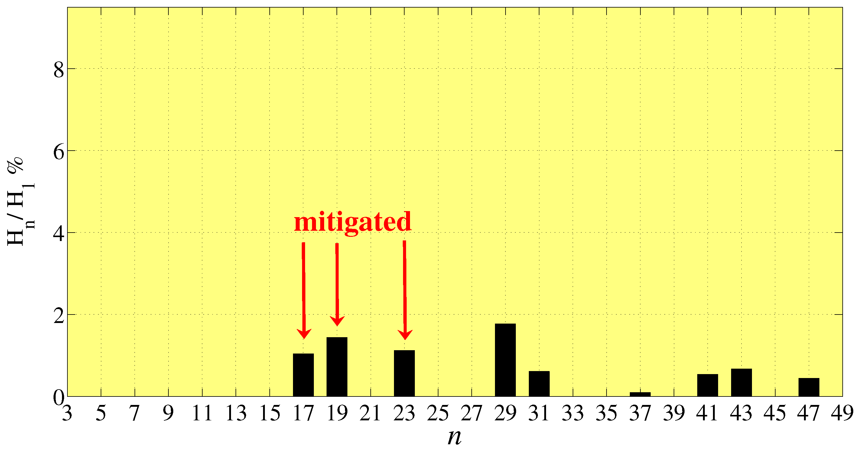
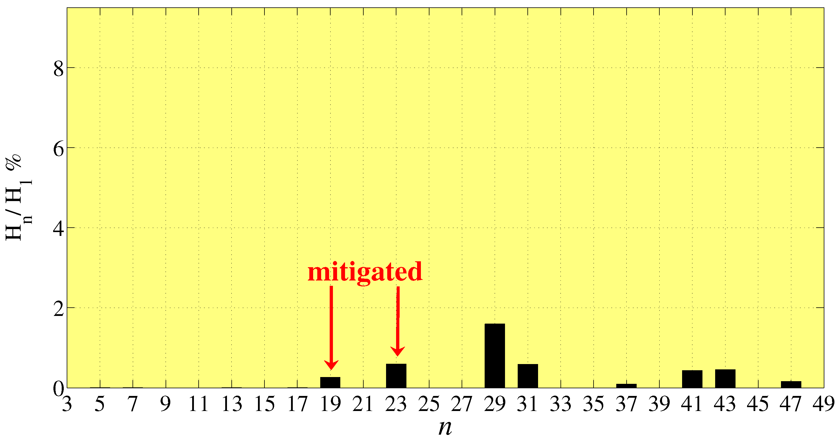
Also in this case, it is observed that the harmonic spectrum of a single-phase 33-level inverter is the same as a three-phase 17-level inverter in Figure 7. Figure 8 shows the harmonic analysis that highlights that in three-phase configuration, the first not-mitigated harmonic is the 29th, the previous are eliminated except the 19th and 23rd, which are mitigated [24,25].
Table 2 shows the parameter C values and the obtained THD%. In the same table, the THD% values achieved by the pulse active width modulation in [21] are indicated. It can be observed that for three-phase configurations the proposed technique returns lower THD than the procedure in [21], this is more evident for nine-level inverters. As observed before, the same harmonic spectrum and THD% are obtained for three-phase configuration of level 2 × 2 n + 1 and single-phase configuration of level 2 · 2 n + 1 + 1 .
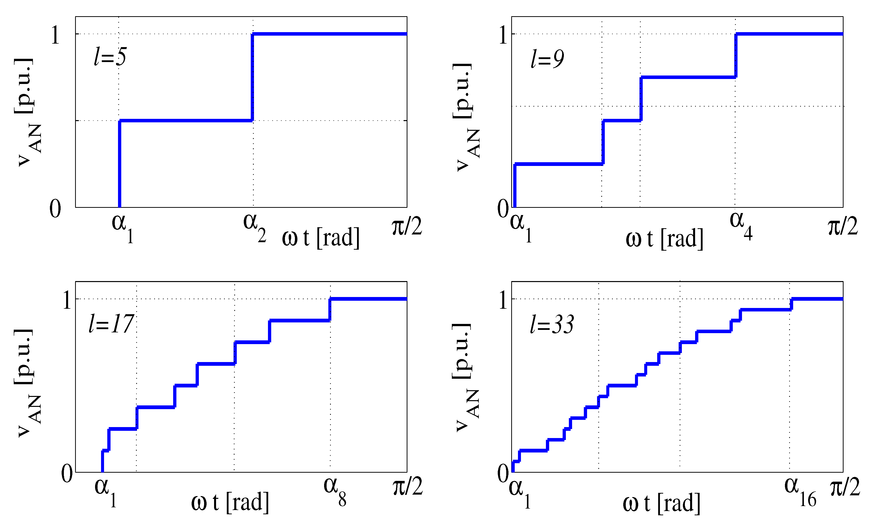
Figure 9 shows the output voltages, in p.u., for 5-level, 9-level, 17-level and 33-level inverters, highlighting, for the last case, the very good quality of the waveform.

4. Experimental Results

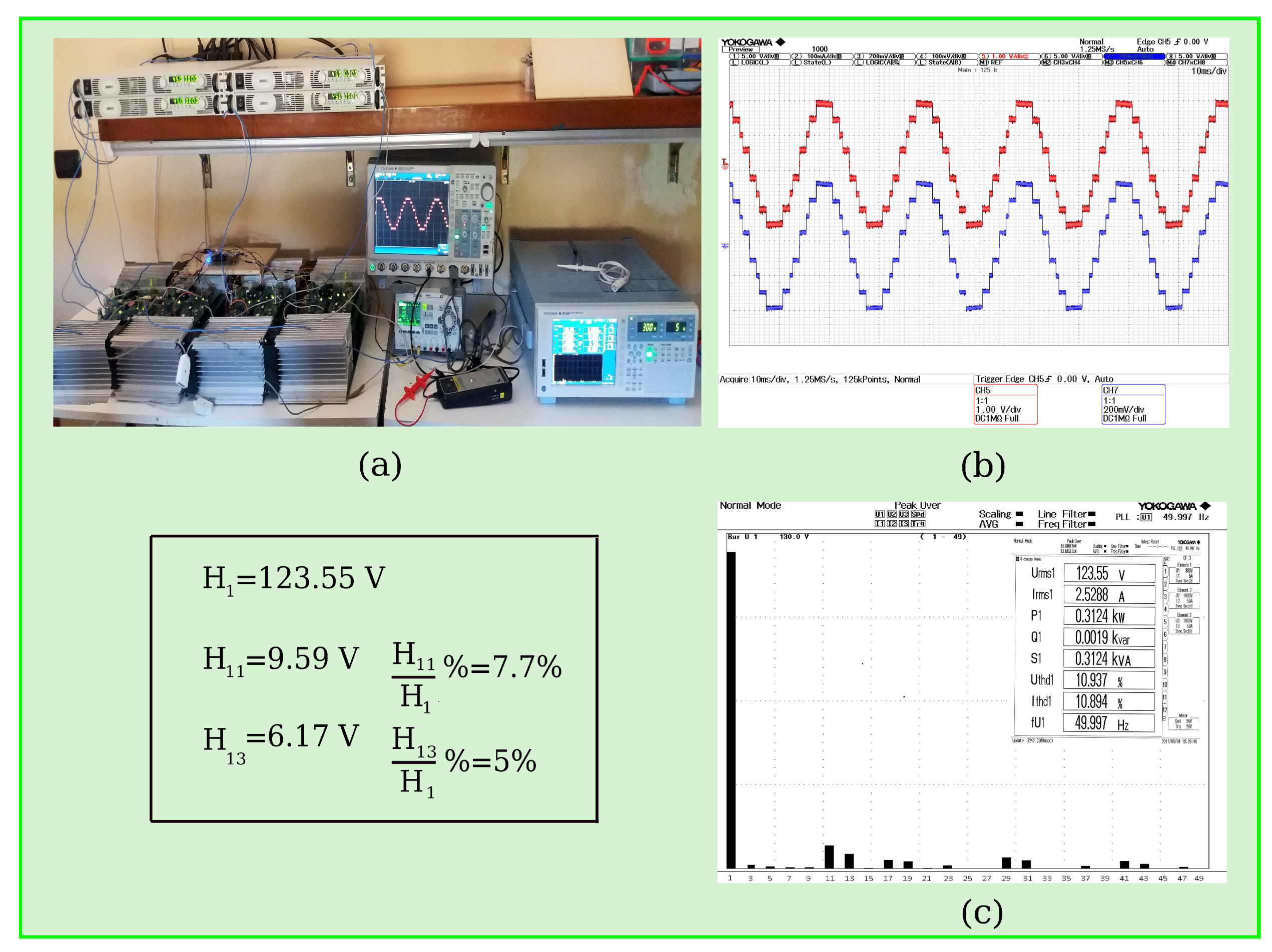
In order to validate the proposed procedure, an experimental prototype of a single-phase CHB nine-level inverter is built. It is shown in Figure 10a. The voltage dc source is equal to 45 V and the connected load has R = 48.80 Ω and L = 0.94 m H . Figure 10b shows the output voltage and current waveforms and Figure 10c the harmonic analysis of the output voltage [26,27]. Considering until the 49th harmonic, the THD%, measured is equal to 10.94 % , which is very close to the corresponding computed value that is 10.89 % .

5. Conclusions and Remarks

In this paper, a new general formula, valid for cascaded multilevel inverters having s dc sources and a number of levels l = 2 s + 1 with s = 2 n n = 1 , 2 , 3 , . . . , has been proposed to compute s switching angles that eliminate n + 1 harmonics and their respective multiple from output voltage waveform. The formula has been demonstrated by a mathematical proof. Some examples have been discussed. Very low THD% have been obtained; for the thirty-three level topology, the obtained THD% = 3.47 % for single-phase configuration and 2.34 % for the three-phase one. A very efficient configuration is the nine-level three-phase CHB inverter that has returned THD% = 5.59 % lower than the value obtained by applying the procedure in [21], which is 9.92 % . In order to validate the proposed procedure, a prototype of a nine-level inverter has been built and experimental results have been carried out in terms of a harmonic spectrum and THD%. Experimental analysis has shown the accuracy of the proposed procedure.
The features of the proposed procedure can be summarized as follows:
  • The formulation is very easy, in fact the switching angles vector is obtained through a very simple rule as highlighted by the examples; directly, these rules could allow obtaining the manual solution without any computation;
  • The computational cost of the procedure is low;
  • For three-phase configurations and in particular for a nine-level inverter, a great number of low order harmonics are eliminated and/or mitigated, returning a very low THD. The first not mitigated harmonic is the 17th, allowing a light and cheap filter;
  • Three-phase configuration of level 2 · 2 n + 1 presents the same harmonic spectrum of a single-phase configuration of level 2 · 2 n + 1 + 1 ;
  • Switching angles and THD do not depend on the modulation index.

Author Contributions

The authors equally contributed to this paper (conceptualization, software implementation and validation), moreover, they provided to formal analysis and preparation of the manuscript along the whole review process. C.C. is principal investigator of the founding project. All authors have read and agreed to the published version of the manuscript.

Funding

This research was funded by PRIN2017 OF FUNDER grant number MS9F49 G.

Conflicts of Interest

The authors declare no conflicts of interest.

References

  1. Mao, W.; Zhang, X.; Hu, Y.; Zhao, T.; Wang, F.; Li, F.; Cao, R. A research on cascaded H-bridge module level photovoltaic inverter based on a switching modulation strategy. Energies 2018, 12, 1851. [Google Scholar] [CrossRef] [Green Version]
  2. Huang, Q.; Huang, A.; Yu, R.; Liu, P.; Yu, W. High-Efficiency and High-Density Single-PhaseDual-Mode Cascaded Buck–Boost Multilevel Transformerless PV Inverter With GaN AC Switches. IEEE Trans. Power Electron. 2018, 54, 7474–7488. [Google Scholar]
  3. Babaei, E.; Buccella, C.; Cecati, C. New 8-Level Basic Structure for Cascaded Multilevel Inverters with Reduced Number of Switches and DC Voltage Sources. J. Circuits Syst. Comput. 2019, 28, 1950038-1–1950038-16. [Google Scholar] [CrossRef]
  4. Hasan, M.M.; Abu-Siada, A.; Islam, S.M.; Muyeen, S.M. A novel Concept for Three-Phase Cascaded Multilevel Inverter Topologies. Energies 2018, 11, 268. [Google Scholar] [CrossRef] [Green Version]
  5. Taghvaie, A.; Adabi, J.; Rezanejad, M. A Self-Balanced Step-Up Multilevel Inverter Based on Switched-Capacitor Structure. IEEE Trans. Power Electron. 2018, 55, 199–209. [Google Scholar] [CrossRef]
  6. Liu, M.; Li, Z.; Yang, X. Tracking Control of Modular Multilevel Converter Based on Linear Matrix Inequality without Coordinate Transformation. Energies 2020, 13, 1978. [Google Scholar] [CrossRef]
  7. Srndovic, M.; Zhetessov, A.; Alizadeh, T.; Familiant, Y.L.; Grandi, G.; Ruderman, A. Simultaneous Selective Harmonic Elimination and THD Minimization for a Single-Phase Multilevel Inverter With Staircase Modulation. IEEE Trans. Ind. Appl. 2018, 54, 1532–1541. [Google Scholar] [CrossRef]
  8. Aguilera, R.P.; Acuña, P.; Lezana, P.; Konstantinou, G.; Wu, B.; Bernet, S.; Agelidis, V.G. Selective Harmonic Elimination Model Predictive Control for Multilevel Power Converters. IEEE Trans. Power Electron. 2017, 52, 2416–2426. [Google Scholar] [CrossRef] [Green Version]
  9. Perez-Basante, A.; Ceballos, S.; Konstantinou, G.; Pou, J.; Kortabarria, I.; de Alegria, I.M. A Universal Formulation for Multilevel Selective-Harmonic-Eliminated PWM With Half-Wave Symmetry. IEEE Trans. Power Electron. 2019, 54, 945–957. [Google Scholar] [CrossRef]
  10. Najjar, M.; Moeini, A.; Bakhshizadeh, M.K.; Blaabjerg, F.; Farhangi, S. Optimal Selective Harmonic Mitigation Technique on Variable DC Link Cascaded H-Bridge Converter to Meet Power Quality Standards. IEEE J. Emerg. Select. Topics Pow. Electron. 2016, 4, 1107–1116. [Google Scholar] [CrossRef]
  11. Dahidah, M.; Konstantinou, G.; Agelidis, V. A review of multilevel selective harmonic elimination PWM: Formulations, solving algorithms, implementation and applications. IEEE Trans. Power Electron. 2015, 50, 4091–4106. [Google Scholar] [CrossRef]
  12. Buccella, C.; Cecati, C.; Cimoroni, M.G.; Razi, K. Analytical method for pattern generation in five-level cascaded H-bridge inverter using selective harmonic elimination. IEEE Trans. Ind. Electron. 2014, 61, 5811–5819. [Google Scholar] [CrossRef]
  13. Lee, S.S.; Chu, B.; Idris, N.R.N.; Goh, H.H.; Heng, Y.E. Switched-battery boost-multilevel inverter with GA optimized SHEPWM for standalone application. IEEE Trans. Ind. Electron. 2016, 63, 2133–2142. [Google Scholar] [CrossRef]
  14. Kavousi, A.; Vahidi, B.; Salehi, R.; Bakhshizadeh, M.K.; Farokhnia, N.; Fathi, S.H. Application of the bee algorithm for selective harmonic elimination strategy in multilevel inverters. IEEE Trans. Power Electron. 2012, 27, 1689–1696. [Google Scholar] [CrossRef]
  15. Massrur, H.R.; Niknam, T.; Mardaneh, M.; Rajaei, A.H. Harmonic elimination in multilevel inverters under unbalanced voltages and switching deviation using a new stochastic strategy. IEEE Trans. Ind. Informat. 2016, 12, 716–725. [Google Scholar] [CrossRef]
  16. Etesami, M.H.; Vilathgamuwa, D.M.; Ghasemi, N.; Jovanovic, D.P. Enhanced metaheuristic methods for selective harmonic elimination technique. IEEE Trans. Ind. Informat. 2018, 14, 5210–5220. [Google Scholar] [CrossRef]
  17. Panda, K.P.; Panda, G. Application of swarm optimisation-based modified algorithm for selective harmonic elimination in reduced switch countmultilevel inverter. IET Power Electron. 2018, 11, 1472–1482. [Google Scholar] [CrossRef]
  18. Mohammadhossein, E.; Negareh, G.; Don Mahinda, V.; Wynand, L.M. Particle swarm optimisation-based modified SHE method for cascaded H-bridge multilevel inverters. IET Power Electron. 2017, 10, 18–28. [Google Scholar]
  19. Panda, K.P.; Lee, S.S.; Panda, G. Reduced Switch Cascaded Multilevel Inverter with New Selective Harmonic Elimination Control for Standalone Renewable Energy System. IEEE Trans. Ind. Appl. 2019, 55, 7561–7574. [Google Scholar] [CrossRef]
  20. Buccella, C.; Cecati, C.; Cimoroni, M.G.; Kulothungan, G.; Edpuganti, A.; Kumar Rathore, A. A Selective Harmonic Elimination Method for Five-Level Converters for Distributed Generation. IEEE J. Emerg. Select. Topic Pow. Electron. 2017, 5, 775–785. [Google Scholar] [CrossRef]
  21. Buccella, C.; Cimoroni, M.G.; Tinari, M.; Cecati, C. A new pulse active width modulation for multilevel converters. IEEE Trans. Power Electron. 2019, 34, 7221–7229. [Google Scholar] [CrossRef]
  22. Ahmed, M.; Sheir, A.; Orabi, M. Real-Time Solution and Implementation of Selective Harmonic Elimination of Seven-Level Multilevel Inverter. IEEE J. Emerg. Select. Topic Pow. Electron. 2017, 5, 1700–1709. [Google Scholar] [CrossRef]
  23. Buccella, C.; Cimoroni, M.G.; Patel, V.; Saif, A.M.; Tinari, M.; Cecati, C.; Babaei, E. Harmonic elimination procedure for cascaded multilevel inverters having a particular even number of dc sources. In Proceedings of the 44th Annual Conference of the IEEE Industrial Electronics Society The IECON 2018 (IECON2018), Washington, DC, USA, 21–23 October 2018; pp. 1249–1254. [Google Scholar]
  24. CENELEC EN 50160, “Voltage characteristics of electricity supplied by public distribution systems”. 2001. Available online: https://standards.globalspec.com/std/13493775/EN (accessed on 5 June 2020).
  25. CIGRE WG 56–05, “Harmonics, characteristic parameters, methods of study, estimates of existing values in the network”. Electra 1981, 35–54. Available online: https://www.scirp.org/(S(351jmbntvnsjt1aadkposzje))/reference/ReferencesPapers.aspx?ReferenceID=67207 (accessed on 5 June 2020).
  26. DE10-Nano board. 2017. Available online: https://www.terasic.com (accessed on 5 June 2020).
  27. Quartus Prime version 16.1.0. 2007. Available online: https://fpgasoftware.intel.com/16.1/?edition=standard (accessed on 5 June 2020).
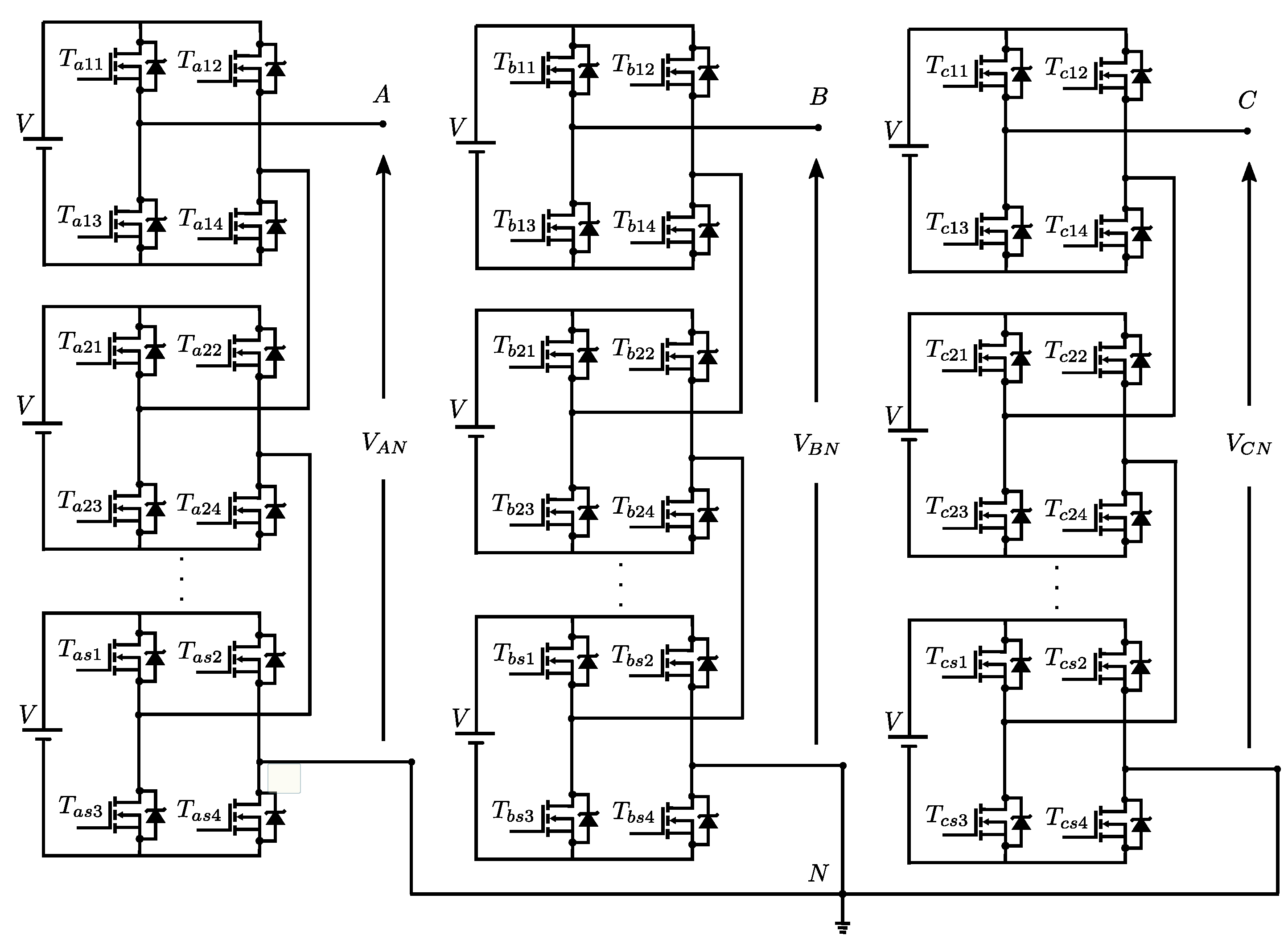
Figure 1. Three-phase cascaded H-bridge (CHB) l-level inverter configuration.
Energies 13 03740 g001
Figure 2. Switching angles, dc voltage source and fundamental harmonic behaviors as a function of m for a single-phase 5-level inverter.
Energies 13 03740 g002
Figure 3. Switching angles, dc voltage source and fundamental harmonic behaviors as a function of m for a three-phase 9-level inverter.
Energies 13 03740 g003
Figure 4. Flow chart of the proposed algorithm.
Energies 13 03740 g004
Figure 5. Percentage values of harmonics amplitudes H n with respect to the fundamental H 1 for the CHB 5-level inverter: (a) single-phase configuration, (b) three-phase configuration.
Energies 13 03740 g005
Figure 6. Percentage values of harmonics amplitudes H n with respect to the fundamental H 1 for three-phase 9-level configuration.
Energies 13 03740 g006
Figure 7. Percentage values of harmonics amplitudes H n with respect to the fundamental H 1 for three-phase 17-level configuration.
Energies 13 03740 g007
Figure 8. Percentage values of harmonics amplitudes H n with respect to the fundamental H 1 for three-phase 33-level configuration.
Energies 13 03740 g008
Figure 9. Output voltages for 5-level, 9-level, 17-level and 33-level inverters.
Energies 13 03740 g009
Figure 10. Measurements: (a) experimental prototype of single-phase CHB 9-level inverter, (b) output voltage and current waveforms, (c) harmonic analysis of the output voltage waveform (130 V, (1–49)).
Energies 13 03740 g010
Table 1. Grid codes EN 50160 and CIGRE WG 36-05.
OddHarmonics EvenHarmonics
Not multipleof 3Multipleof 3
n l n (%)n l n (%)n l n (%)
563522
7591.541
113.5150.56....100.5
133210.5>100.2
172>210.2
191.5
231.5
251.5
>250.2+32.5/n
Table 2. Parameter C and THD%.
Level lParameter CTHD%THD% [21]THD%THD% [21]
Single-PhaseSingle-PhaseThree-PhaseThree-Phase
51.21417.3018.1411.5312.80
91.24511.539.925.599.92
171.2585.595.153.473.74
331.2673.472.562.342.56