Article

The Influence of Groove Structure Parameters on the Maximum Flow Resistance of a Rectangular Narrow Channel

State Key Laboratory of Eco-Hydraulics in Northwest Arid Region of China, School of Water Resources and Hydropower, Xi’an University of Technology, Xi’an 710048, China
*
Author to whom correspondence should be addressed.
Energies 2020, 13(14), 3716; https://doi.org/10.3390/en13143716
Submission received: 13 June 2020 / Revised: 15 July 2020 / Accepted: 16 July 2020 / Published: 19 July 2020

Abstract

:
In the hydraulically suspended passive shutdown assembly, in order to prevent the liquid suspension rod falling too fast and the outer tube from violent impact, it is necessary to study the way to increase flow resistance. This study added grooves to the wall of the narrow channel to increase its flow resistance. Using the RNG k-ε turbulence model in Fluent, the influence of the groove structure parameters and the Reynolds number on the flow resistance of the narrow channel was discussed to find the optimal groove structure parameters. The results showed that the flow resistance of the narrow channel increased with the increase in the concave–convex ratio, and when the concave–convex ratio was small, the flow resistance decreased with increased groove thickness, while when the concave–convex ratio exceeded a certain critical value, the flow resistance increased with increased groove thickness. Additionally, the growth rate slowed down when the concave–convex ratio was greater than 3:1. As the unit length decreased, the flow resistance first increased and then decreased. When the unit length was 6 mm, the flow resistance reached the maximum. With the increase in the Reynolds number, the intensity of the local high-turbulence kinetic energy clearly increased.

1. Introduction

Narrow channels are widely used in nuclear reactors, aerospace, microelectronics and other fields [1]. Especially within reactor engineering, the core subassemblies of some research reactors and power reactors are typical rectangular narrow channels with large aspect ratios [2,3,4]. The liquid suspension passive shutdown technology mainly uses the internal fluid flow power of the system to ensure that the liquid suspension rod is suspended in the normal working position (Figure 1a). In the case of an unprotected loss of flow accident in the system, the hydraulic thrust of the liquid suspension rod can no longer make the liquid suspension rod suspend, resulting in rod drop and the reactor trip being completed independently. (Figure 1b). When the liquid suspension rod falls into the buffer throttle components, the liquid suspension rod and the buffer throttle components form a narrow slot channel. Increasing the resistance of the narrow channel can increase the buffering effect, and prevent the suspension rod from falling too fast and striking the bottom outer tube [5,6]. Therefore, using the rectangular narrow channel as a case study, the present study increased flow resistance in the channel by optimizing its shape and structure. In recent years, there have been many studies that focused on the shapes of channel pits and ribs to improve the flow between the channel wall and the channel [7].
Kimura and Tsutahar [8] studied the flow resistance of cylinders with circular arc pits in the channel wall with varying depths. Terekhov et al. [9] experimented with circular arc pits placed on one side of a rectangular channel, and reported on the resulting pressure field and flow structure in the channel. Taslim et al. [10] investigated the rib height effect and pointed out that pressure loss increases remarkably with increasing rib height. Moon and Lau [11] reported that cylindrical pits have a higher heat transfer coefficient and lower flow resistance than spherical pits. Some studies [12,13,14,15] have reported on the influences of dimple parameters on heat transfer and pressure loss characteristics in a dimple-roughened channel in terms of dimple depth, print diameter, spacing and arrangement. Bilen et al. [16] and Ramadhan et al. [17] studied the effects of different groove shapes (circle, rectangle, trapezoid, and triangle) on the heat transfer performance and flow loss of a channel. Mohammed et al. [18] studied the loss in pressure drop and friction coefficient of zigzag, curved and periodic microchannels, with a comparison to that of straight microchannels, and found that the losses in pressure drop of all the channels were greater than those of straight microchannels, with the greatest loss observed in the zigzag channels. Nho et al. [19] studied the total pressure losses of narrow channels with 11 different types of top structures incorporating ribs on the in-line turbine cascades, and found that the total pressure loss was smallest at the top of the double ribs and the slope groove on the pressure side. Fangyang Yuan [20] studied the flow resistance and bubble transport in a helical static mixer, and found that the pressure drop increases with the Reynolds number, and the increment is larger when the Reynolds number is higher. Ostanek and Thole [21] studied the loss in pressure drop along different forms of ribs, and identified a large loss of pressure of ribs with edges. Zhang et al. [22] established a spherical convex structure in the upstream area of a circular groove to study the effects of different numbers of spherical convexities and positions on the heat transfer and pressure loss of a groove channel. Zhao et al. [23] measured the flow resistance of the spherical pit wall in a rectangular channel to study the influence of channel pit spacing, and found that the flow resistance of the concave surface increased by 90% compared with that of a smooth wall. Yu et al. [24], using a theoretical model and the reciprocating friction test method, analyzed the interaction between micro pits when hydrodynamic pressure was produced by the surface texture. The study found that under a fixed micro pit diameter, depth and area ratio, the change in the relative position of the micro pits had a great influence on friction reduction by the surface texture. Peng [25] used the Fluent software to study the friction resistance coefficient of laminar flow of monophase water in circular channels of different widths. Past studies have established the relationship between the friction coefficient and the characteristic length of the equivalent hydraulic diameter of the ring joint, with equations proposed to represent this relationship having good accuracy. However, there are few studies that have focused on increasing flow resistance by arranging continuous grooves on the wall of a narrow channel.
Based on the previous research mentioned above, the current study used numerical simulation to analyze the effect of groove structure parameters on flow resistance of a rectangular narrow channel. The current study focused on flow resistance in a rectangular narrow channel under different unit lengths, concave–convex ratios, groove thicknesses and narrow channel widths. The results of the present study can be helpful as a reference for further research on flow in narrow channels containing grooves.

2. Physical Model

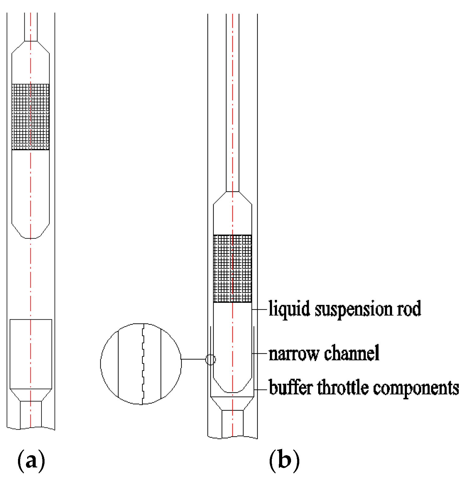
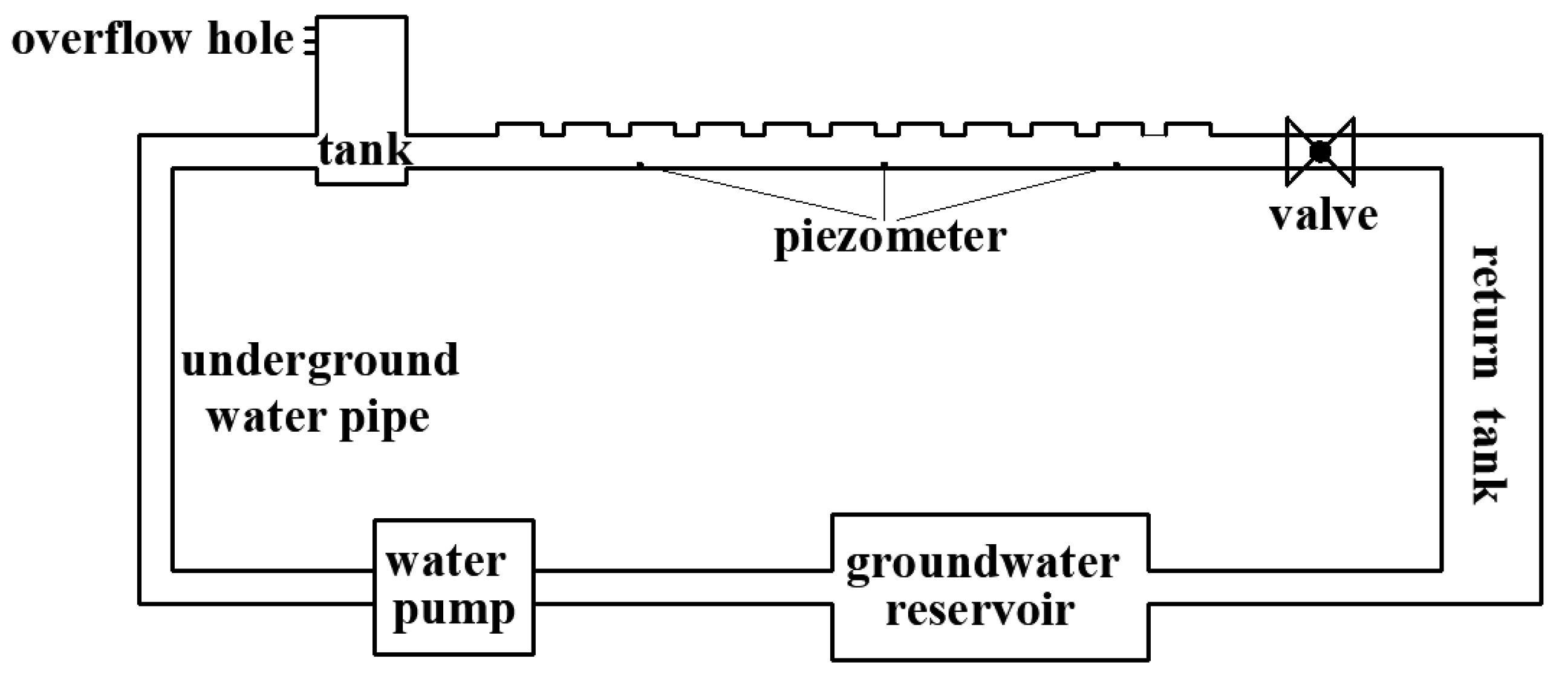
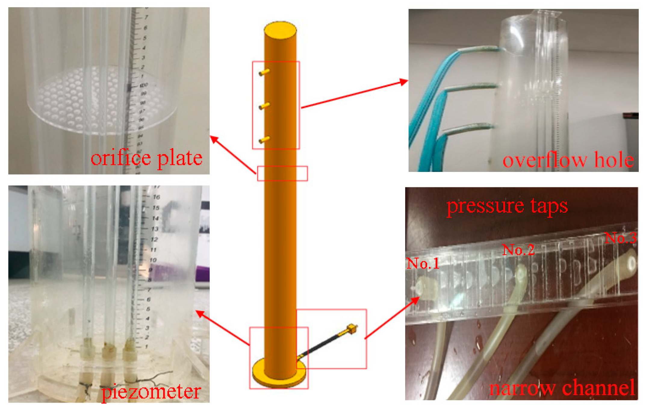
2.1. Experimental Equipment

The experimental device consisted of three parts, namely, a water tank section, a narrow channel overflow section and a water circulation system. The total height of the water tank was 2 m, and three overflow holes were installed on the side of the water tank at heights of 1.4 m, 1.6 m and 1.8 m to control the water level. An orifice plate was installed in the middle of the water tank to stabilize the water flow. Three pressure taps were installed on the narrow channel overflow section at 0.1 m, 0.18 m and 0.26 m. In addition, pressure taps fixed to the side wall of the water tank were connected to rubber hoses to measure pressure along the system.
During the experiment, the water pump supplied water from a groundwater reservoir to the water tank from the top through the water diversion pipe. After stabilization of the water flow in the water tank, water flowed into the narrow channel overflow section. The valve controlled the flow at the end of the narrow channel. The water returned to the underground reservoir through the return tank to form a circulation system.
Figure 2 is a schematic diagram of the narrow channel experimental device, whereas Figure 3 shows a detailed diagram of the narrow channel experimental device. The entire experimental device was constructed using plexiglass with a thickness of 5 mm.

2.2. Measurement Methods and Experimental Conditions

The groove structure parameters include unit lengths, L u ; the concave–convex ratio, R ; narrow channel widths, W ; and groove thickness, H . A narrow channel unit includes a groove and a salient, and L u refers to the total length of the groove and salient. R refers to the ratio of concave groove length to convex groove length in a narrow channel unit; W refers to the distance between the upper and lower wall surfaces of a narrow channel; H is the thickness of the groove.
The narrow channel experiment incorporated four kinds of wall conditions, namely a smooth wall, a 7.5:2.5 cogging wall surface, a 10:5 cogging wall surface and a 4.5:1.5 cogging wall surface. Experimental water heads of three different heights were included in the narrow channel experiment, namely 1.8 m, 1.6 m and 1.4 m. The W was 3 mm and the H was 1 mm. The narrow channel computational model, illustrated in Figure 4, used a 7.5:2.5 cogging wall surface as an example.
During the experiment, the pressure drop along the system was calculated by reading the head difference measurements of three piezometers. The flow rate in the system was measured using a measuring cylinder and stopwatch, and the measurement error was reduced by taking the average value of ten measurements. Table 1 shows the specific test conditions.

3. Numerical Model

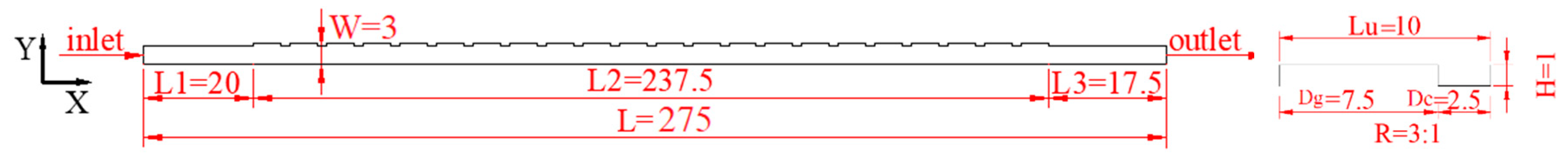
3.1. Establishment of the Numerical Model

The current experimental model was used as a prototype system to further knowledge on the influence of the groove structure parameters on flow resistance of a rectangular narrow channel. The commercial computational fluid dynamics (CFD) software Fluent16.0 was used to conduct a three-dimensional (3D) numerical simulation. The current study ensured equal experimental model sizes and experimental conditions between the numerical simulation and the experimental model. The narrow channel is a regular area, so we used the structural grid to mesh it. In order to better observe the flow near the wall, the mesh was locally refined in the groove and convex part.
The inlet boundary of the model was set as the velocity condition, the outlet boundary as the pressure outlet condition and the sidewall as a no-slip wall. The roughness of the wall boundary was assumed to be 0.005 mm in accordance with the characteristics of the experimental materials.

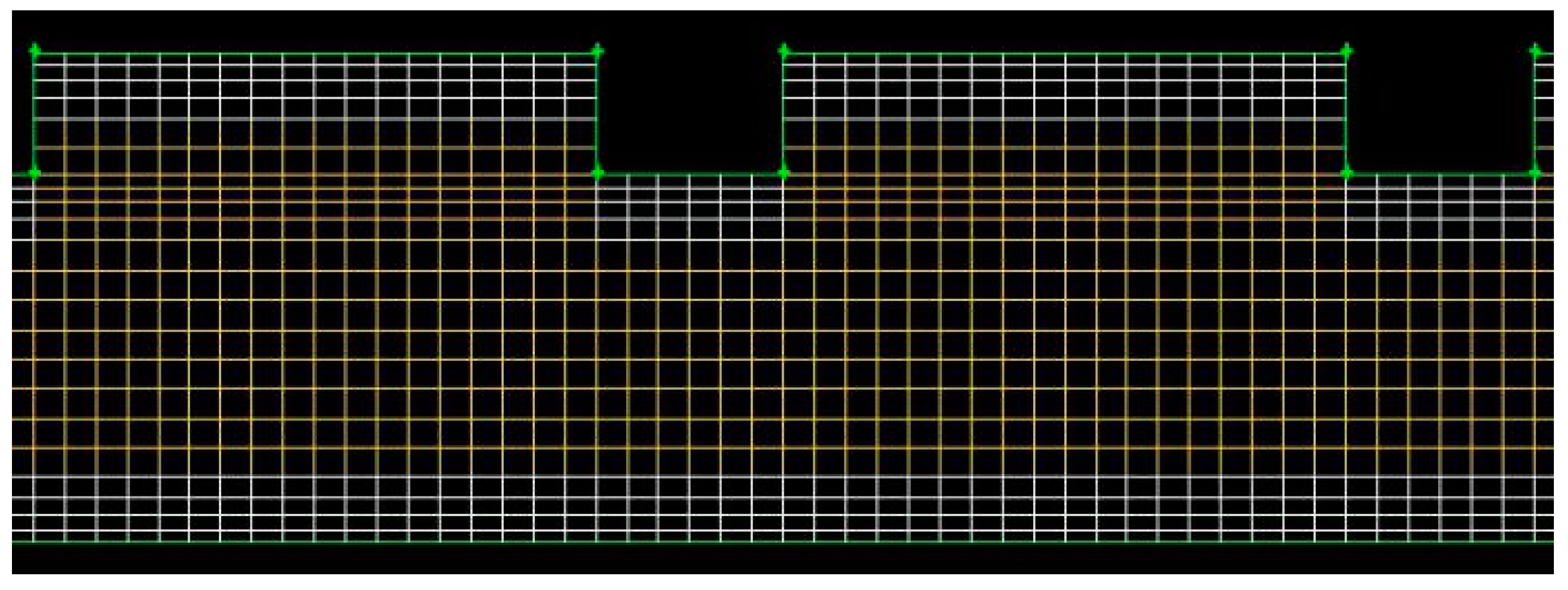
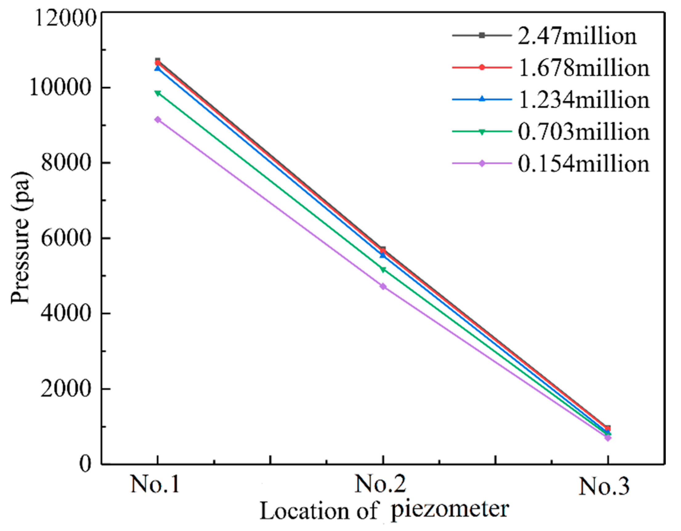
3.2. Meshing and Grid Independence Study and Turbulence Model Study
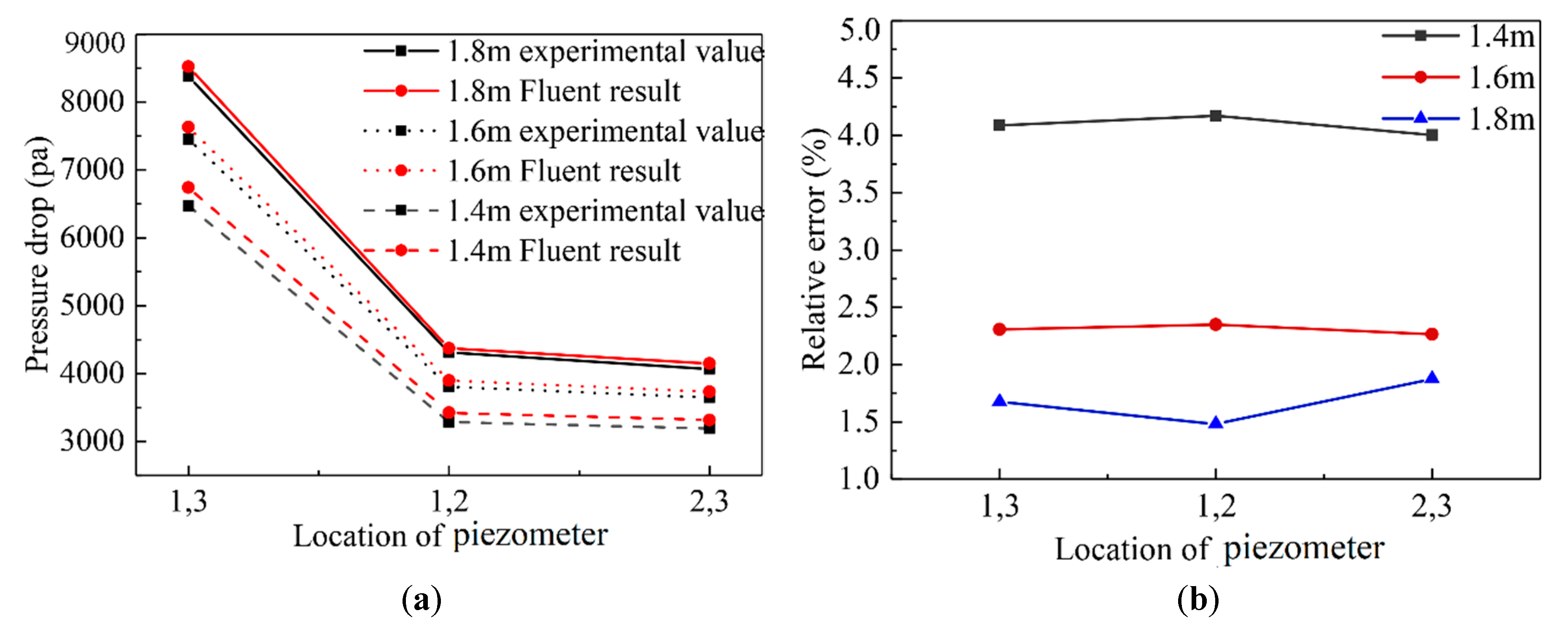
Before numerical simulation, the meshing and grid independence study and the turbulence model study are important steps to ensure the calculation results. In order to select a suitable turbulence model, taking the 4.5:1.5 cogging wall surface as an example, four turbulence models, k ω SST standard k-ε, realizable k-ε and RNG k-ε, were selected to calculate the pressure drop when the head height was 1.8 m (Re = 3750). The results were compared with the experimental data. The calculation results are shown in Table 2. It can be seen that the RNG k-ε turbulence model is the closest to the experimental dates, and the relative errors are less than 5%. Therefore, the RNG k-ε turbulence model is selected for calculation. When choosing a suitable number of grids, a trade-off between prediction accuracy and computational economy is needed. The pressure drop of five grid sizes was calculated, and the meshes of the grooves are shown in Figure 5. The mesh sizes and calculation results are shown in Figure 6. It can be clearly seen from Figure 6 that when the grid size is greater than 1.678 million, the change of the calculation results caused by a further increase in the grid can be ignored.

4. Model Validation

The established numerical model was used to simulate the 7.5:2.5 cogging wall surface at different head heights of 1.4 m, 1.6 m and 1.8 m. The pressure of the center section along the W was extracted to obtain the pressure of No. 1, No. 2, and No. 3 piezometers, and then the pressure drop between the piezometers was calculated. Figure 7 shows a comparison between the pressure difference obtained by the simulation calculation and the experimental results. It is clear that the relative error between the simulated value and the experimental value is less than 5% and, therefore, the numerical model simulation results are in good agreement with those of the physical model. The present study therefore confirmed that the numerical model was able to accurately simulate the influence of groove distribution on the resistance of a narrow channel. Table 3 shows all the narrow channel calculation models.

5. Effect of Groove Structure Parameters on the Flow Resistance of a Narrow Channel

5.1. Data Reduction

The influence of different groove structure parameters on the flow resistance of the narrow channel was studied under the same Reynolds number Re. The narrow channel overflow section includes three parts, L 1 is the development length before groove section, L 2 is the groove section and L 3 is the development length after the groove section. In order to reflect the influence of groove on the flow resistance of the narrow channel more accurately, we used the friction factor of the groove section to show the flow resistance of the narrow channel.

5.2. R and H

Nine kinds of R were simulated to study the influence of the R and the H on the flow characteristics of the narrow channel, namely, ratios of 1:4, 1:3, 1:2, 1:1, 2:1, 3:1, 4:1, 5:1 and 6:1. These nine R were studied under two H of 1 mm and 0.5 mm, two L u of 6 mm and 10 mm and a constant W of 3 mm. The friction factor of the narrow channel under different R and H were calculated, and are plotted in Figure 8.
Figure 8 shows that under a constant W and L u , the basic law of the friction factor changes of an H of 1 mm and 0.5 mm was consistent. In other words, with increasing R , there was a gradual increase in the friction factor of the narrow channel, with the rate of growth first increasing and then decreasing. Under an L u of 6 mm, the friction factor of the narrow channel increased with decreasing H under an R less than the critical value of 1.5:1. However, with an R greater than the critical value of 1.5:1, the friction factor of the narrow channel increased with increasing H . Under an L u of 10 mm and R less than the critical value of 1:1.4, the friction factor increased with decreasing H , whereas when the R was greater than the critical value of 1:1.4, the friction factor increased with increasing H .
As an example, a constant L u of 10 mm with different R of 1:4, 1:2, 2:1 and 4:1 and different H of 0.5 mm and 1 mm was studied to examine the influence of the R on the flow resistance of the narrow channel. The plotted results are shown in Figure 9 and Figure 10.
Under an H of 0.5 mm, the flow first diffused and then contracted as it passed through the groove. With increasing R , flow gradually fully diffused, followed by the flow turbulence gradually intensifying. Under an H of 1 mm and R < 1:1.4, a large vortex was formed in the groove and the flow turbulence was weak, whereas under an R > 1:1.4, the flow first diffused and then contracted when passing through the groove, with the flow turbulence clearly enhanced.
Under an R < 1:1.4 and H of 0.5 mm, the flow through the groove first diffused and then contracted, forming large and small vortices in front and behind the groove, respectively, which resulted in the consumption of a lot of energy. Under an H of 1 mm, a large vortex was formed in the groove, which consumed little energy. Under an R > 1:1.4, flow through the groove first diffused and then contracted. The diffusion and contraction observed under an H of 1 mm were significantly enhanced compared with those under an H of 0.5 mm. Therefore, it is clear that when the R increased from 1:4 to 4:1, the falls in unit pressure under H of 0.5 mm and 1 mm showed an increasing trend and a threshold point (critical R ) could be identified.

5.3. L u and W

Three kinds of W were simulated to study the influence of W and L u on the friction factor of the narrow channel, namely, 3 mm, 2 mm and 1 mm. Five types of wall surface were investigated, i.e., groove wall surfaces with L u of 15 mm, 10 mm, 6 mm, 4 mm and smooth wall. Based on the simulation results of the concave–convex ratio and the depth of the groove, the H was 1 mm and the concave–convex ratio was 3 mm. The numerical model was used to simulate the friction factor of the narrow channels with different widths and wall forms. Figure 11 shows the calculation results.
Figure 11 shows that under a change in the wall surface form from smooth to grooved, the friction factor increases significantly. For a narrow channel with a width of 3 mm, the friction factor increases by 160–222% when the wall surface changes from smooth to grooved. For a narrow channel with widths of 3 mm and 1 mm, a change in the wall surface from smooth to groove results in an increase in the friction factor by 189–289% and 203–340%, respectively. The results illustrated that the flow resistance of a narrow channel can be increased by arranging grooves on its surface. When the wall form is constant, the friction factor increases significantly with W decreasing from 3 mm to 1 mm, and the growth rate is increasingly faster. For a smooth wall surface, the friction factor increased by 156% when W was reduced from 3 mm to 1 mm. For narrow channels with L u of 15 mm, 10 mm, 6 mm and 4 mm, the friction factor increased by 199%, 226%, 250% and 246%, respectively, when W was reduced from 3 mm to 1 mm. Under a set W , the flow resistance of the narrow channel first increased and then decreased with a decrease L u (increase in groove density), and reached a maximum at 6 mm. This observation was closely related to the flow pattern through the grooves.
The influence of L u on the flow characteristics of a narrow channel was further explored using a W of 3 mm, R of 3:1 and H of 1 mm as an example, and by studying the change in pressure along the system under different L u (Figure 12). Because the grooves were continuously and uniformly arranged on the wall of the channel, some narrow channel L u s were taken as examples for the study of narrow channel streamline (Figure 13), velocity (Figure 14) and turbulent kinetic energy (Figure 15).
As illustrated in Figure 12, pressure at the center line of the narrow channel decreased gradually with some variation. In the smooth sections at the beginning and tail of the narrow channel, pressure decreased in a straight line, whereas in the groove section, pressure decreased with some variation, and the pressure in the groove section decreased at a faster rate than that in the smooth section. This observation shows that the addition of grooves can effectively reduce flow resistance. With a decrease in L u (an increase in cell density), the variation in the pressure drop curve for the groove section decreased. At an L u of 4 mm, there was negligible variation in the curve, and the curve was basically a straight line; the slopes of the curves ranked according to L u had the order of 6 mm > 10 mm and 15 mm > 4 mm, which is consistent with the relationships shown in Figure 11.
Figure 13 shows the flow patterns in the narrow channel under a constant W of 3 mm and different L u of 15 mm, 10 mm, 6 mm and 4 mm. Under an L u of 15 mm, the water flow through the groove first diffused and then contracted, forming large and small vortices in the front and back of a groove, respectively. The flow through the groove in the narrow channel with an L u of 10 mm and 6 mm was similar to that with an L u of 15 mm, although under an L u of 15 mm, the shape of the small vortex behind the groove gradually became obvious, and gradually moved upstream. Under an L u of 6 mm, the small and large vortices behind and in front of the groove, respectively, merged. However, under a reduced L u of 4 mm, the small vortex behind the groove disappeared, and the water flow formed a large vortex in the groove. The flow pattern under the groove moved in parallel to the lower wall surface, and no diffusion and contraction process was evident. Therefore, when the L u was reduced from 15 mm to 4 mm, the unit pressure of the narrow channel first increased and then decreased.
Figure 14 shows the contours of velocity in a narrow channel unit under a constant W of 3 mm and varying L u of 15 mm, 10 mm, 6 mm and 4 mm. It is clear that in all cases, there were obvious local zones of reduced and increased velocity in the groove and salient, respectively. This observation can be explained by the presence of a significant reflux in the groove, and a reflux trapped in a groove typically exhibits lower velocity. In the area below the groove, the water flow was less affected by the diffusion and contraction in the groove, and the flow pattern tended to be horizontal, resulting in lower turbulence of water flow and higher velocity. With a reduction in L u from 15 mm to 4 mm, the range of the low-velocity zone in the groove expanded. Under an L u of 4 mm, the entire range of the groove could be classified as a low-velocity zone, whereas the range of the local high-velocity zone under the salient decreased. Under an L u of 4 mm, the local high-velocity zone formed a shape close to a straight line. However, the flow velocity of the entire narrow channel became increasingly uniform.
Figure 15 shows the contours of turbulent kinetic energy (TKE) in the narrow channel under a constant W of 3 mm and different L u of 15 mm, 10 mm, 6 mm and 4 mm. It is clear that in all cases, there are obvious local high turbulent energy regions at the windward area of grooves. This observation can be explained by the fact that the high velocity grade with the concentrated streamlines take places here. In addition, with a reduction in L u from 15 mm to 4 mm, there was first an increase followed by a decrease in the local high-turbulence kinetic energy zone downstream of the grooves. The local high-turbulence kinetic energy zone under an L u of 4 mm was significantly smaller than that under other L u , and the local low-turbulence kinetic energy zone in the lower wall of the narrow channel first decreased and then increased. The largest turbulent flow energy in the groove was observed under an L u of 6 mm, consistent with previous conclusions.

6. Effect of the Reynolds Number on Flow Resistance

In order to explore the effect of the Reynolds number on the flow resistance of the narrow channel, the flow structure in the narrow channel with different Reynolds numbers was simulated with an R of 3:1, groove thickness of 1 mm, W of 3 mm and L u of 6 mm as examples. With the Reynolds number increasing from 2250 to 6000, the vortex shape of the narrow channel was consistent (Figure 13c), there were a large vortex and small vortices in the front and back of a groove, and there was no significant change in the size and relative position of the vortex. The variation of contours of turbulence kinetic energy in a narrow channel with different Reynolds numbers is shown in Figure 16. In this figure, it is indicated that with the increase in the Reynolds number, the local high-turbulence kinetic energy zone appeared in the windward region of the grooves. The difference was that the larger the Reynolds number, the greater the turbulence intensity in the local high-turbulence kinetic energy zone. This explains why the flow resistance increases with the Reynolds number.

7. Conclusions

The current study used the numerical simulation to study the effects of groove structure parameters and the Reynolds number on flow resistance. The reliability of the numerical model was verified by physical experiments with consistent representations of model size and experimental conditions. The main conclusions are outlined below:
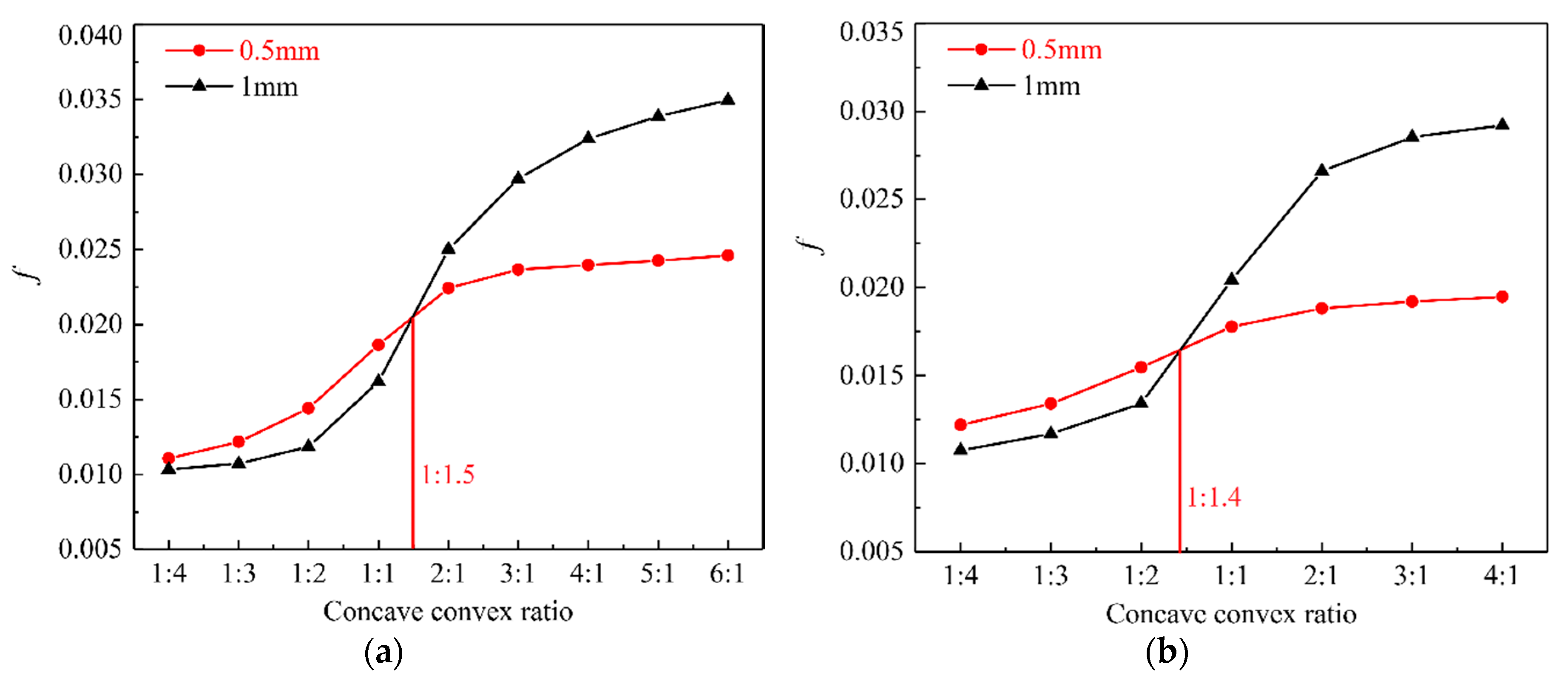
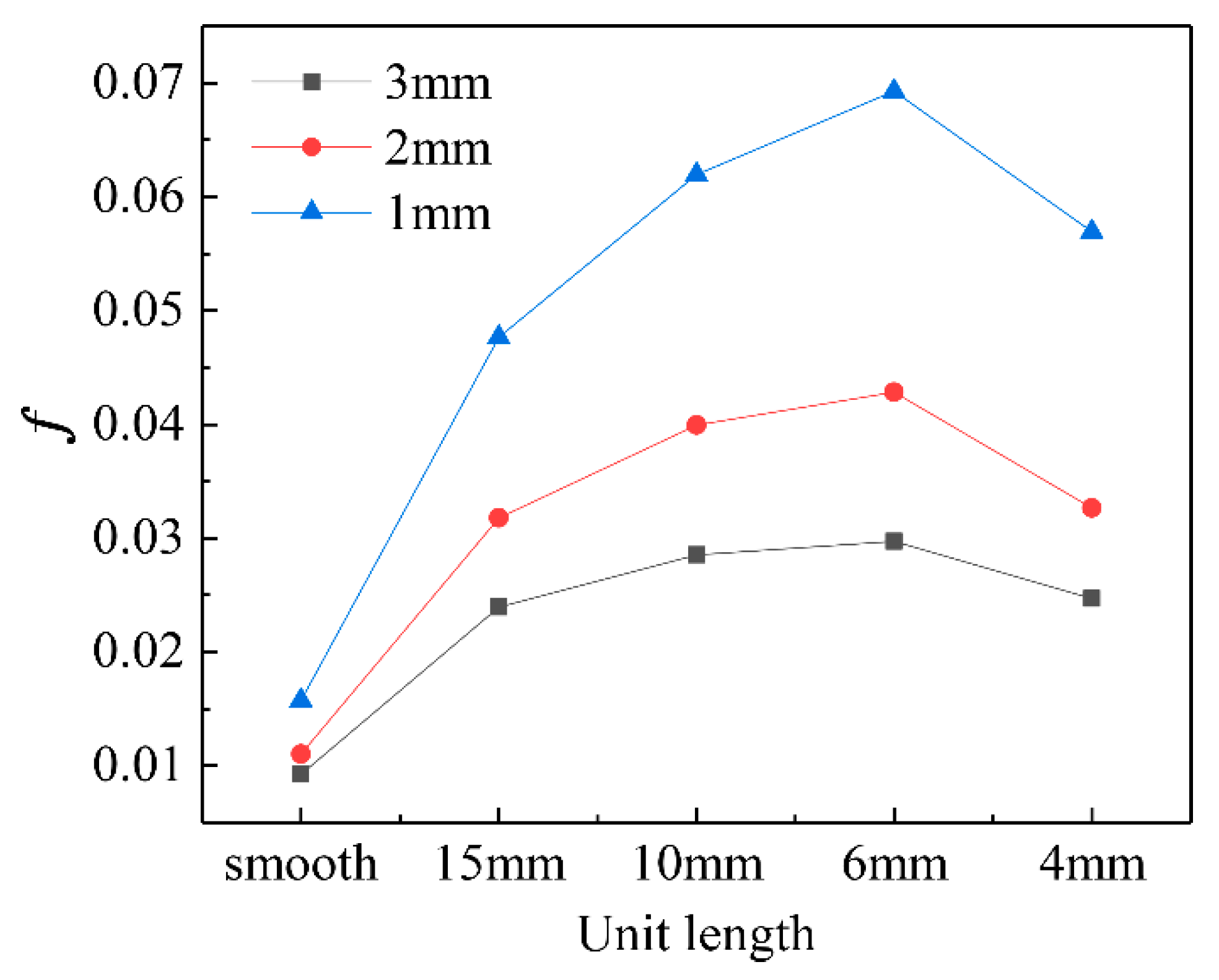
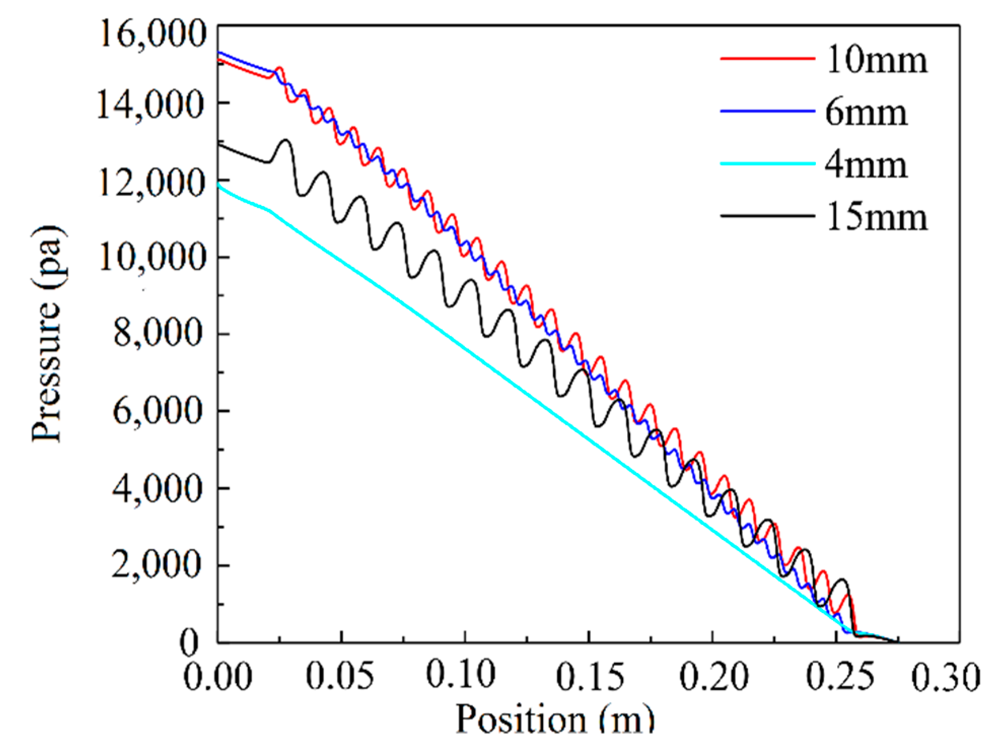
  • The arrangement of grooves on the inner wall of a narrow channel effectively increased its flow resistance. The flow resistance of the narrow channel increased with the increase in the concave–convex ratio, with a decelerating growth rate. Under a small concave–convex ratio, the fall in unit pressure increased with decreasing groove depth. In contrast, under a concave–convex ratio larger than a certain critical point, the fall in unit pressure increased with increasing groove depth. This critical concave–convex ratio varied with the groove structure, with the critical concave–convex ratios being 1.5:1 and 1:1.4 under unit lengths of 6 mm and 10 mm, respectively.
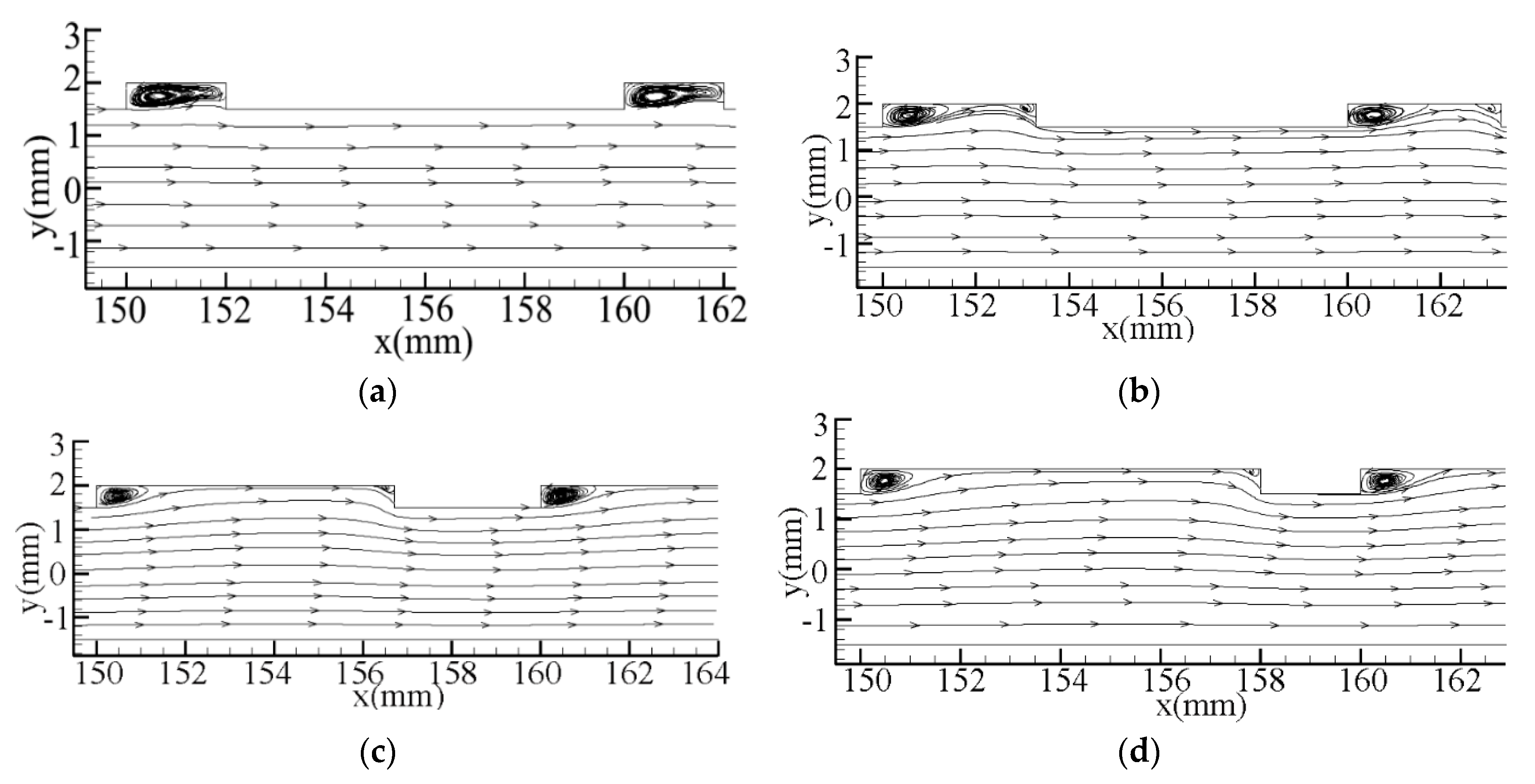
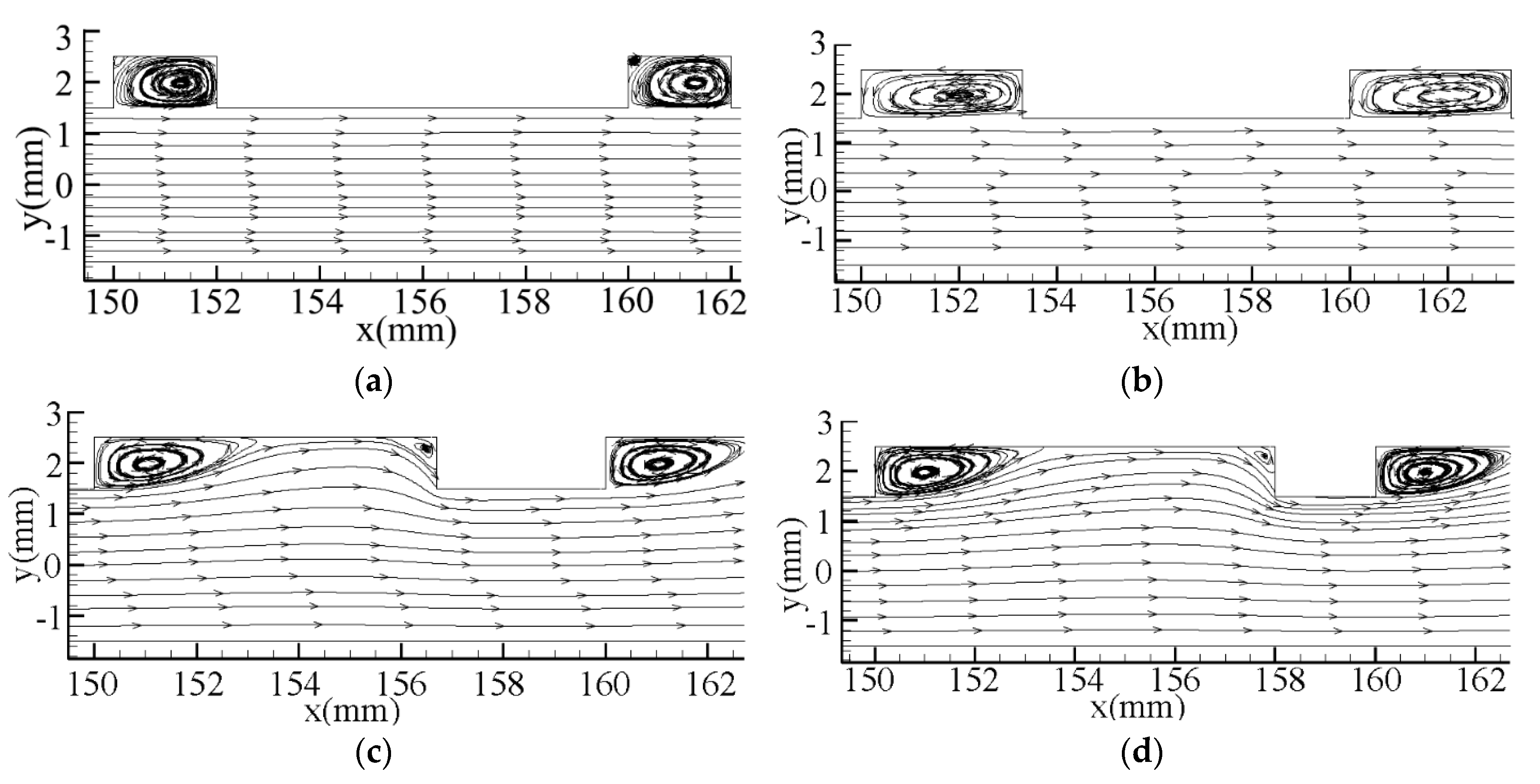
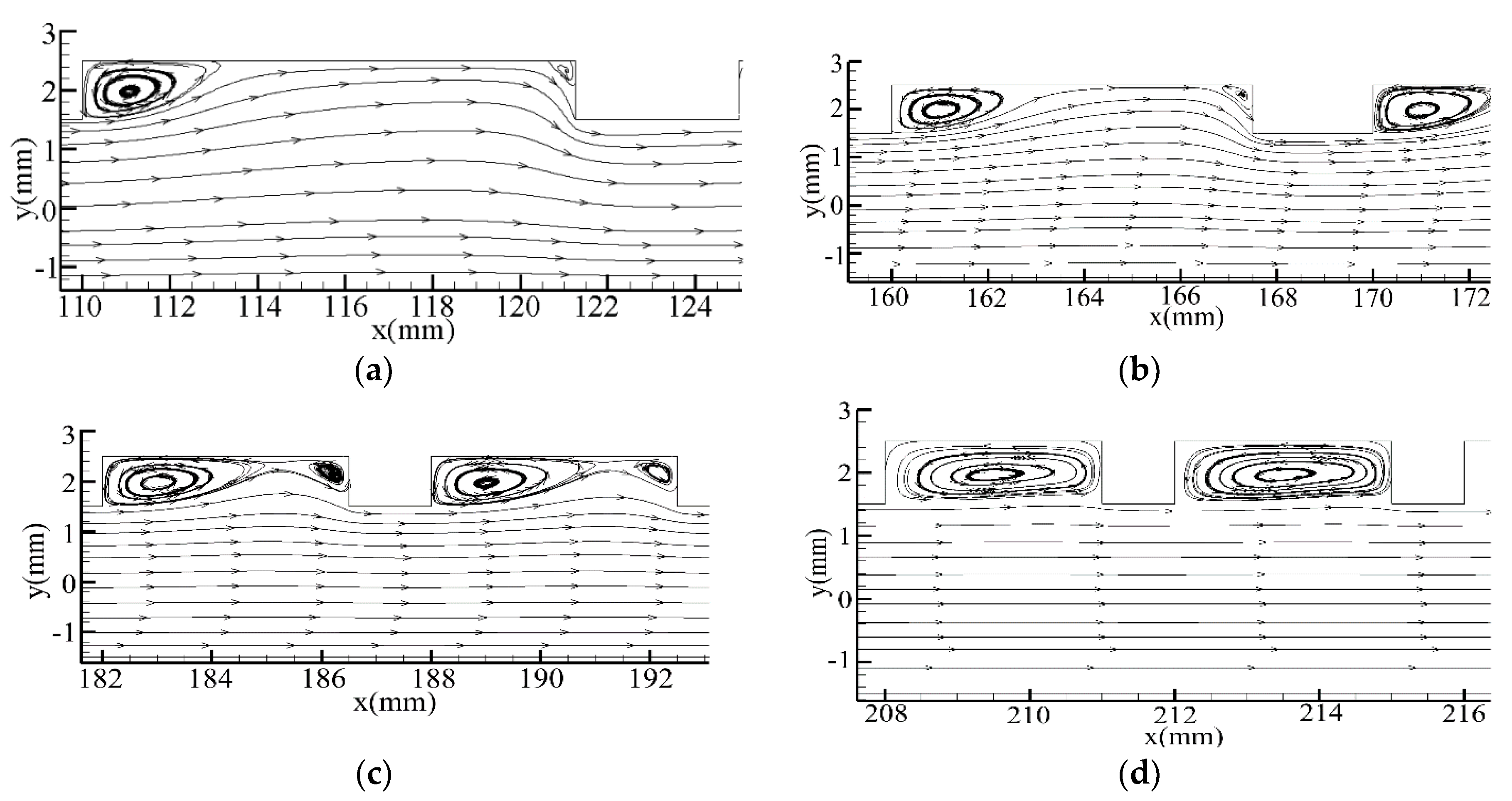
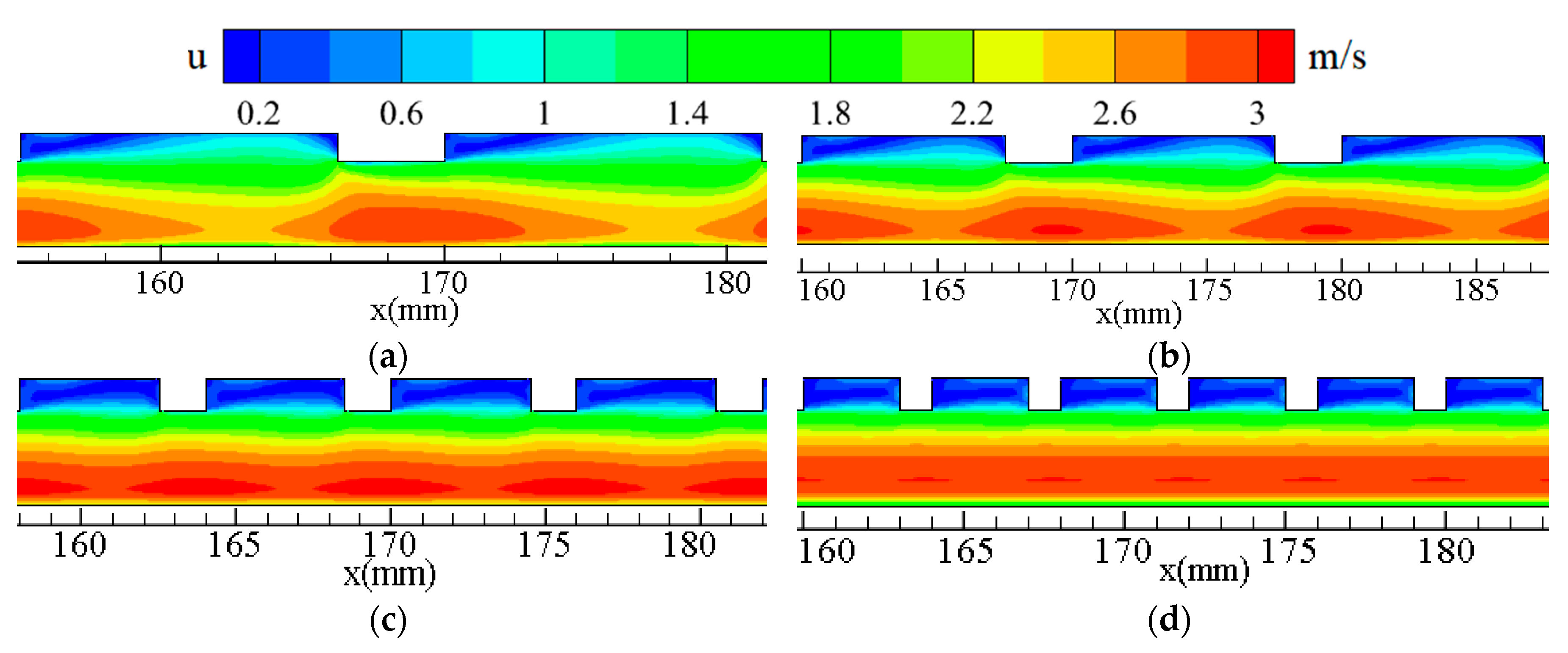
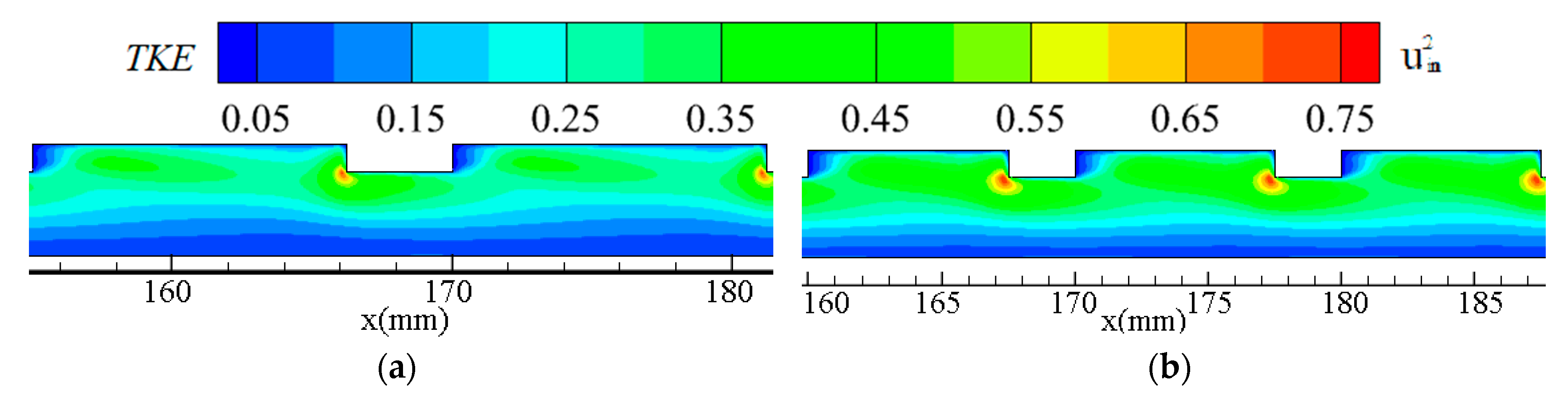
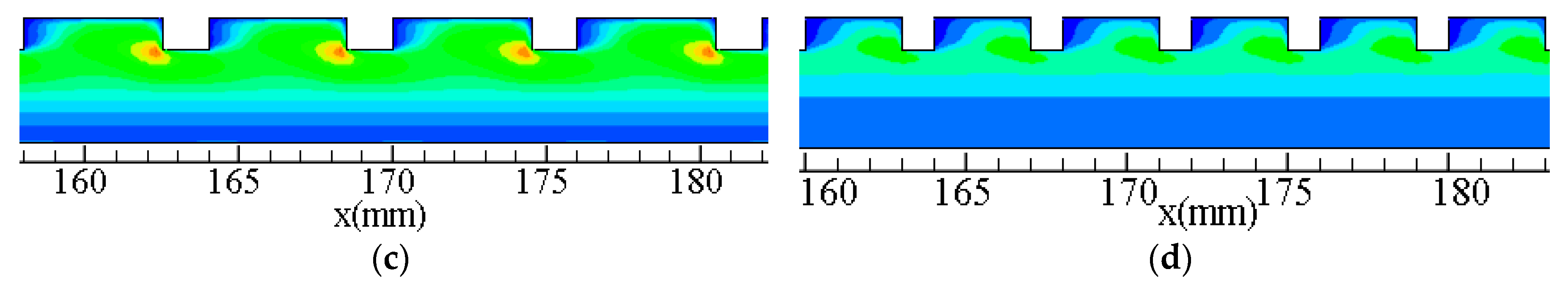
  • When reducing the unit length of the narrow channel from 15 mm to 6 mm, its flow resistance first increased and then decreased. Flow resistance of a narrow channel ordered by unit length showed an order of 6 mm > 10 mm > 15 mm > 4 mm. This was because by decreasing the unit length, the shape of the small vortex behind the groove gradually became obvious, and gradually moves upstream. The diffusion and contraction of the fluid in the groove become more and more sufficient. Under a reduced unit length of 4 mm, the water flow formed a large vortex in the groove, and no diffusion and contraction process was evident. At the same time, the intensity of the local high-turbulence kinetic energy zone in the windward region of the grooves shows a trend of first increasing and then decreasing.
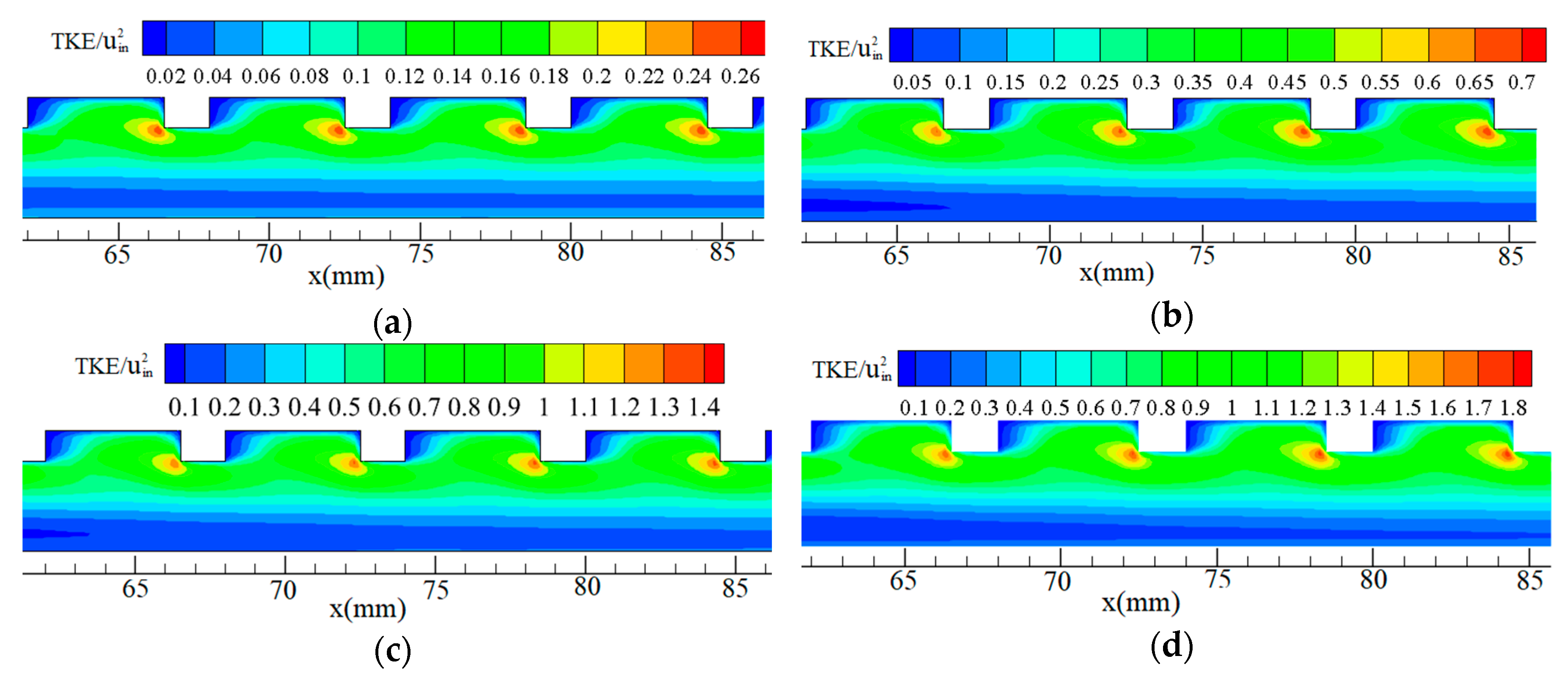
  • With the increase in the Reynolds number, there was no significant change in the vortex shape of the narrow channel; the basic law of contours of turbulence kinetic energy was consistent; and the windward regions of the grooves all had a local high-turbulence kinetic energy zone, but the intensity of the local high-turbulence kinetic energy clearly increases. This explains why the flow resistance increases with the Reynolds number.

Author Contributions

Conceptualization, G.L.; methodology, X.L., P.L.; software, D.C., S.L.; validation, D.C., S.L.; formal analysis, D.C.; investigation, G.L.; resources, G.L.; data curation, G.L.; writing—original draft preparation, D.C.; writing—review and editing, D.C.; visualization, D.C.; supervision, J.Z.; project administration, G.L.; funding acquisition, G.L. All authors have read and agreed to the published version of the manuscript.

Funding

This research was supported by Key R&D Program Projects in Shanxi Province [grant 2018SF-352], National Natural Science Foundation of China [grant 51579206], Science and Technology Projects of Shaanxi Water Conservancy Department [grant 2017slkj-17], the National Natural Science Foundation-sponsored project [grant 11605136].

Conflicts of Interest

The authors declare no conflict of interest.

Nomenclature

W narrow channel width, mm
L u unit length, mm
R concave-convex ratio, mm
H groove depth, mm
D g groove length, mm
D c convex groove length, mm
L narrow channel length, mm
L 1 length of the smooth starting part, mm
L 2 length of groove part, mm
L 3 length of the smooth exiting part, mm
P pressure, pa
P s t a r t starting position pressure of groove part, pa
P e x i s t exiting position pressure of groove part, pa
Re Reynolds number based on hydraulic diameter
u i n mean velocity at the inlet, m s−1
u Velocity magnitude, m s−1
TKEturbulence kinetic energy, m2 s−2
x streamwise distance of narrow channel, mm
y spanwise distance of narrow channel, mm
Δ P pressure drop of narrow channel, pa
f friction factor
μ flow dynamic viscosity, N s m−2

References

  1. Xu, J.J.; Chen, B.D.; Wang, X.J.; Xiong, W.Y. Experimental research and numerical simulation of flow field near the narrow side in a rectangular narrow channel. J. Hydrodyn. 2006, 6, 770–775. [Google Scholar]
  2. Wang, Z.H.; Jia, D.N.; Liu, R.L. A Overview of the Intensified Heat Exchange Research of Two phase Flows in a Narrow gap Channel. J. Eng. Therm. Energy Power 2002, 17, 329–331. [Google Scholar]
  3. Hu, Z.-C.; Ma, H.G. Review of flow and boiling heat transfer in micro-scale channels. Energy Res. Inf. 2003, 3, 125–132. [Google Scholar]
  4. Xu, J.; Chen, B.; Wang, X. Analysis and Discussion of Flow Boundary Layer in Fully Turbulent of Narrow Rectangular Channel. Nucl. Power Eng. 2011, 32, 95–98. [Google Scholar]
  5. Yuan, H.; Kuang, B.; Liu, P.; Wang, X.; Li, Y. Experimental validation of the rod-dropping analysis program for hydraulically suspended passive shutdown assembly. Appl. Sci. Technol. 2019, 46, 79–84. [Google Scholar]
  6. Peng, G.; Kuang, B.; Wang, X.; Liu, P.; Yuan, H. Performance analysis of a moving body in passive shutdown subassembly for sodium cooled fast reactor. Appl. Sci. Technol. 2019, 46, 116–121. [Google Scholar]
  7. Burgess, N.K.; Oliveira, M.M.; Ligrani, P.M. Nusselt Number Behavior on Deep Dimpled Surfaces Within a Channel. Trans. ASME Ser. C J. Heat Transf. 2003, 125, 11–18. [Google Scholar] [CrossRef]
  8. Kimura, T.; Tsutahara, M. Fluid dynamic effects of grooves on circular cylinder surface. AIAA J. 1991, 29, 2062–2068. [Google Scholar] [CrossRef]
  9. Kumar, P. Numerical investigation of fluid flow and heat transfer in trapezoidal microchannel with groove structure. Int. J. Therm. Sci. 2019, 136, 33–43. [Google Scholar] [CrossRef]
  10. Taslim, M.E.; Darryl, E. Metzger Memorial Session Paper: Experimental Heat Transfer and Friction in Channels Roughened With Angled, V-Shaped, and Discrete Ribs on Two Opposite Walls. J. Turbomach. 1996, 118, 20. [Google Scholar] [CrossRef]
  11. Moon, S.W.; Lau, S.C. Turbulent Heat Transfer Measurements on a Wall With Concave and Cylindrical Dimples in a Square Channel. In Proceedings of the SME Turbo Expo 2002: Power for Land, Sea, and Air; Amsterdam, The Netherlands , 3–6 June 2002, pp. 459–467.
  12. Kim, K.; Choi, J. Shape Optimization of a Dimpled Channel to Enhance Turbulent Heat Transfer. Numer. Heat Transf. Part A Appl. 2005, 48, 901–915. [Google Scholar] [CrossRef]
  13. Won, S.Y.; Ligrani, P.M. Numerical predictions of flow structure and local nusselt number ratios ALONG and above dimpled surfaces with different dimple depths in a channel. Numer. Heat Transf. 2004, 46, 549–570. [Google Scholar] [CrossRef]
  14. Burgess, N.K.; Ligrani, P.M. Effects Of Dimple Depth on Channel Nusselt Numbers and Friction Factors. J. Heat Transf. 2004, 127, 839–847. [Google Scholar] [CrossRef]
  15. Kim, S.; Lee, Y.J.; Choi, E.Y.; Kwak, J.S. Effect of Dimple Configuration on Heat Transfer Coefficient in a Rotating Channel. J. Thermophys. Heat Transf. 2011, 25, 165–172. [Google Scholar] [CrossRef]
  16. Bilen, K.; Cetin, M.; Gul, H.; Balta, T. The investigation of groove geometry effect on heat transfer for internally grooved tubes. Appl. Therm. Eng. 2009, 29, 753–761. [Google Scholar] [CrossRef]
  17. Ramadhan, A.A.; Al Anii, Y.T.; Shareef, A.J. Groove Geometry Effects on Turbulent Heat Transfer and Fluid Flow. Heat Mass Transf. 2013, 49, 185–195. [Google Scholar] [CrossRef]
  18. Mohammed, H.A.; Gunnasegaran, P.; Shuaib, N.H. Influence of channel shape on the thermal and hydraulic performance of microchannel heat sink. Int. Commun. Heat Mass Transf. 2011, 38, 474–480. [Google Scholar] [CrossRef]
  19. Nho, Y.C.; Park, J.S.; Yong, J.L.; Kwak, J.S. Effects of turbine blade tip shape on total pressure loss and secondary flow of a linear turbine cascade. Int. J. Heat Fluid Flow 2012, 33, 92–100. [Google Scholar] [CrossRef]
  20. Yuan, F.; Cui, Z.; Lin, J. Experimental and Numerical Study on Flow Resistance and Bubble Transport in a Helical Static Mixer. Energies 2020, 13, 1228. [Google Scholar] [CrossRef] [Green Version]
  21. Ostanek, J.K.; Thole, K.A. Effects of Varying Streamwise and Spanwise Spacing in Pin-Fin Arrays. In Proceedings of the ASME Turbo Expo 2012: Turbine Technical Conference and Exposition, Copenhagen, Denmark, 11–15 June 2012; pp. 45–57. [Google Scholar]
  22. Zhang, F.; Wang, X.; Li, J. Flow and heat transfer characteristics in rectangular channels using combination of convex-dimples with grooves. Appl. Therm. Eng. 2017, 113, 926–936. [Google Scholar] [CrossRef]
  23. Zhao, P.; Liu, G.W.; Zhu, X.H.; Liu, Y.F. Influence of dimple space on heat transfer enhancement and pressure loss in a dimpled rectangular channel. J. Aerosp. Power 2009, 24, 2266–2271. [Google Scholar]
  24. Yu, H.W.; Deng, H.S.; Huang, W.; Wang, X.L. Effects of micro-dimple arrangements on tribological performance of sliding surfaces. J. China Univ. Min. Technol. 2011, 40, 943–948. [Google Scholar]
  25. Jun, P. Study on flow friction characteristics of single-phase flow in annular narrow channel. Nucl. Technol. 2019, 42, 86–92. [Google Scholar]
Figure 1. Schematic diagram of liquid-suspended shutdown assembly. (a) The normal working position; (b) Unprotected loss of flow accident.
Energies 13 03716 g001
Figure 2. Schematic diagram of the narrow channel experimental device.
Energies 13 03716 g002
Figure 3. Detailed diagram of the tank and narrow channel.
Energies 13 03716 g003
Figure 4. Schematic diagram of computational model (all dimensions in mm).
Energies 13 03716 g004
Figure 5. The mesh of a computational domain.
Energies 13 03716 g005
Figure 6. Comparison of pressure tap readings under five different mesh sizes.
Energies 13 03716 g006
Figure 7. Comparison of falls in pressure between the experimental and simulation models. (a) Comparison between experimental and simulated values; (b) relative error value of each head.
Energies 13 03716 g007
Figure 8. Variation in the friction factor of the narrow channel under different R and H (Re = 3750). (a) L u = 6 mm; (b) L u = 10 mm.
Energies 13 03716 g008
Figure 9. Flow patterns in a narrow channel under a constant L u of 10 mm, H of 0.5 mm and different R (Re = 3750). (a) 1:4, (b) 1:2, (c) 2:1, (d) 4:1.
Energies 13 03716 g009
Figure 10. Flow patterns in a narrow channel under a constant L u of 10 mm, H of 1 mm and different R (Re = 3750). (a) 1:4, (b) 1:2, (c) 2:1, (d) 4:1.
Energies 13 03716 g010
Figure 11. Variation friction factor of the groove section with different L u and W .
Energies 13 03716 g011
Figure 12. Curves of pressure variation along the system under different L u (Re = 3750).
Energies 13 03716 g012
Figure 13. Streamline diagram in a narrow channel under different L u (Re = 3750). (a) L u = 15 mm; (b) L u = 10 mm; (c) L u = 6 mm; (d) L u = 4 mm.
Energies 13 03716 g013
Figure 14. Contours of velocity in a narrow channel under different L u (Re = 3750). (a) L u = 15 mm; (b) L u = 10 mm; (c) L u = 6 mm; (d) L u = 4 mm.
Energies 13 03716 g014
Figure 15. Contours of turbulence kinetic energy (TKE) in a narrow channel under different L u (Re = 3750). (a) L u = 15 mm; (b) L u = 10 mm; (c) L u = 6 mm; (d) L u = 4 mm.
Energies 13 03716 g015aEnergies 13 03716 g015b
Figure 16. Contours of turbulence kinetic energy (TKE) in a narrow channel under different Reynolds numbers. (a) Re = 2250; (b) Re = 3750; (c) Re = 5250; (d) Re = 6000.
Energies 13 03716 g016
Table 1. Water head and corresponding velocity of each narrow channel overflow experimental section.
Experimental Head
(m)
Smooth Wall
(m∙s−1)
Cogging Wall Surface (m∙s−1)
10:57.5:2.54.5:1.5
1.42.912.352.172.12
1.63.142.552.352.34
1.83.362.712.522.50
Table 2. Comparison between the calculated results of each turbulence model and the experimental data.
Turbulence ModelPressure Tap 1Pressure Tap 2Pressure Tap 3
Pressure
(pa)
Fractional
Error (%)
Pressure
(pa)
Fractional
Error (%)
Pressure
(pa)
Fractional
Error (%)
k ω SST5440.843.43475.431.2677.142.0
k ε Standard10,825.212.65652.811.9928.920.4
k ε Realizable7015.427.03804.724.7789.032.4
k ε RNG9374.32.55016.50.71123.63.8
Experimental date9613.8--5052.2--1167.4--
Table 3. Table of simulated working conditions of groove structure parameters.
Unit Length (mm)Concave–Convex RatioNarrow Channel Width (mm)Groove Thickness (mm)
L u = 15 R = 3:1 W = 3,2,1 H = 1
L u = 10 R = 1:4,1:3,1:2,1:1,2:1,3:1,4:1 W = 3 H = 1,0.5
L u = 6 R = 1:4,1:3,1:2,1:1,2:1,3:1,4:1,5:1,6:1 W = 3 H = 1,0.5
L u = 4 R = 3:1 W = 3,2,1 H = 1
Smooth R = 3:1 W = 3,2,1 H = 1

