1. Introduction
Air pollution is a current global problem [
1]. Exceeding the permissible emission values for harmful compounds and dust concerns large cities in particular [
2,
3,
4] but also occurs locally in the nearest vicinity of the operated machines [
5,
6,
7]. It is one of the reasons of dysphoria [
8,
9], loss of physical motion capacity [
10], and health damage [
11,
12], and also contributes to the development of oncological diseases [
13] and premature death [
14,
15]. Scientists are increasingly recognizing the relationship between human health and air pollution. Research is also conducted among professionals who are prone to pollution by exhaust gases from machine operation due to the nature of their work. Such research concerns various industries, including agriculture, e.g., tractor operators [
5]; forestry, e.g., chainsaw operators [
16]; people working in the mining industry [
17]; and people working in the vicinity of power generators [
18]. All these studies show that people working in such conditions are exposed to elevated concentrations of pollutants, which may translate into increased pathogenic tendencies [
19].
In recognition of the problem related to air pollution, emission limits for harmful exhaust gas compounds for vehicles and non-road machines have been introduced [
20]. In the European Union, vehicles and non-road machinery must comply with the stage standards, which divide the combustion drives in terms of application, output power, and emission indexes, according to the latest regulations (Regulation 2016/1628/EU) [
21]. Meeting the emission standards forces the manufacturers to use innovative solutions for fuel supply systems [
22,
23], exhaust after-treatment systems [
24,
25,
26], and fuel injection control algorithms [
27,
28] and to search for new fuel options [
29,
30,
31,
32]. However, there are groups of machines for which the regulations provide for higher emission limit values [
20] and their drives have a low technical advancement level [
33]. These regulations refer to spark ignition engines used in non-road machines [
21]. Such a design is characterized by a carburettor fuel supply system [
34], lack of a system regulating the spark lead angle [
35], and lack of an exhaust gas cleaning system. These engines are commonly used in low-power shredders used in urbanized areas. Innovations in this group of drives include the use of injection fuels [
36,
37,
38,
39], systems that adapt the drive to the operating conditions [
40,
41], improved durability [
42], and the use of alternative fuels (LPG [
43,
44,
45,
46,
47], ethanol [
48,
49], and methanol [
50]).
A very important aspect of testing emissions of harmful exhaust gas compounds includes the measurements under real operating conditions, which often show imperfections in the tests on test stands [
51]. The research on emissions in agriculture and forestry concerns such machines as, e.g., the farm tractor [
52], harvester, sugar beet harvester [
53], and gasoline sawing machine [
6,
54], as well as low-power (0.7–1.2 kW) combustion engines used in gasoline mowers [
55] or lawnmowers [
56].
There is ongoing research on reducing the emission of agricultural machines, such as hybrid-powered robotic tractors for precision agriculture [
57,
58], biodiesel-based fuel mixture for agricultural tractors [
59,
60], and alcohol-based alternative fuels [
61].
The reduction in emissions of harmful exhaust gas compounds in urbanized areas is particularly important as in these areas, pollutants from various other sources accumulate, e.g., natural [
62], from animal breeding [
63], generated during the construction of buildings [
29], secreted by materials used for construction and maintenance [
64], transport [
65], and fires [
66].
Research on woodchippers mostly focuses on machines used for industrial production of biomass, or forest management. The drive units tested in the available scientific publications are powered by diesel engines with power from 130 to 900 kW [
67,
68]. The research results for both low-power (209 kW) and medium-power (559 kW) woodchippers have already been discussed in the literature [
69], but these still drive units with much higher power than defined by the European standard for spark ignition engines in non-road applications [
21]. The term “small engines” applies exclusively to spark ignition engines when used in chipping machines (due to operating conditions) with power of less than 19 kW [
21].
For this group of drives, we are running research on innovative designs in fuel-air mixture control [
39] and improving the adjustment of branch shredder operating conditions to torque demand [
40,
41,
68,
70]. We assumed that the resulting designs should reduce fuel consumption and the emission of harmful compounds. This article mostly concentrated on the measurement of fuel consumption and harmful emissions under real operating conditions for three designs (one commercial and two prototypes). Moreover, we noticed that there is little research on the emission of harmful exhaust gas compounds during work in urban areas related to green area management, which would improve the air quality in cities [
71]. Determining the hourly emissions of air pollutants from a woodchipper can improve the modelling of the balance associated with the contribution of green infrastructure in urban areas to improve air quality.
2. Materials and Methods
Fuel consumption and exhaust emissions (CO, HC, NO
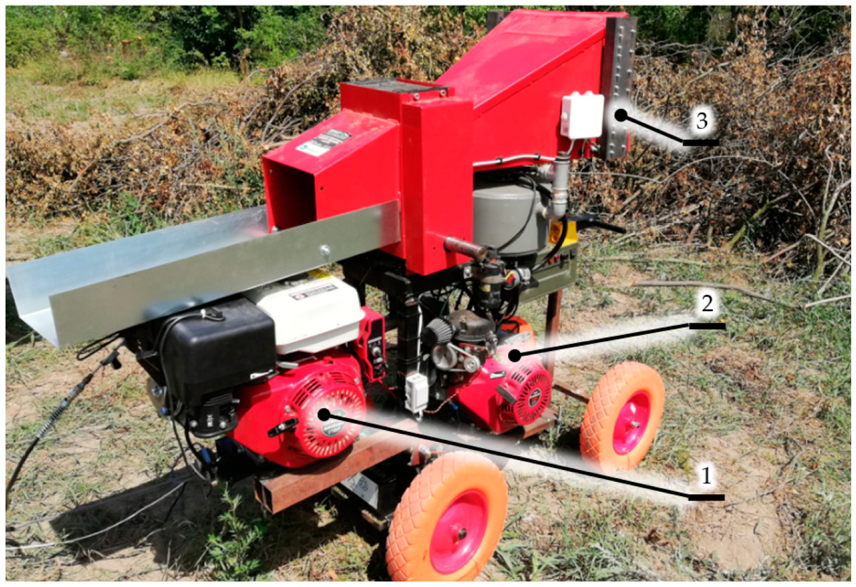
x) were tested for a Red Dragons RS-100 cylindrical woodchipper. The woodchipper is designed for shredding branches with a diameter of up to 100 mm and is a classic example of a machine used for shredding branches of fruit and decorative trees. We tested the machine with a drive motor in three constrictions (
Figure 1). In the first configuration (A), a commercial German GX 390 (License: American Honda Motor Company, Inc., Torrance, CA, United States) (9.5 kW) combustion engine was used. It has a carburettor fuel supply system and no advance angle changing system.
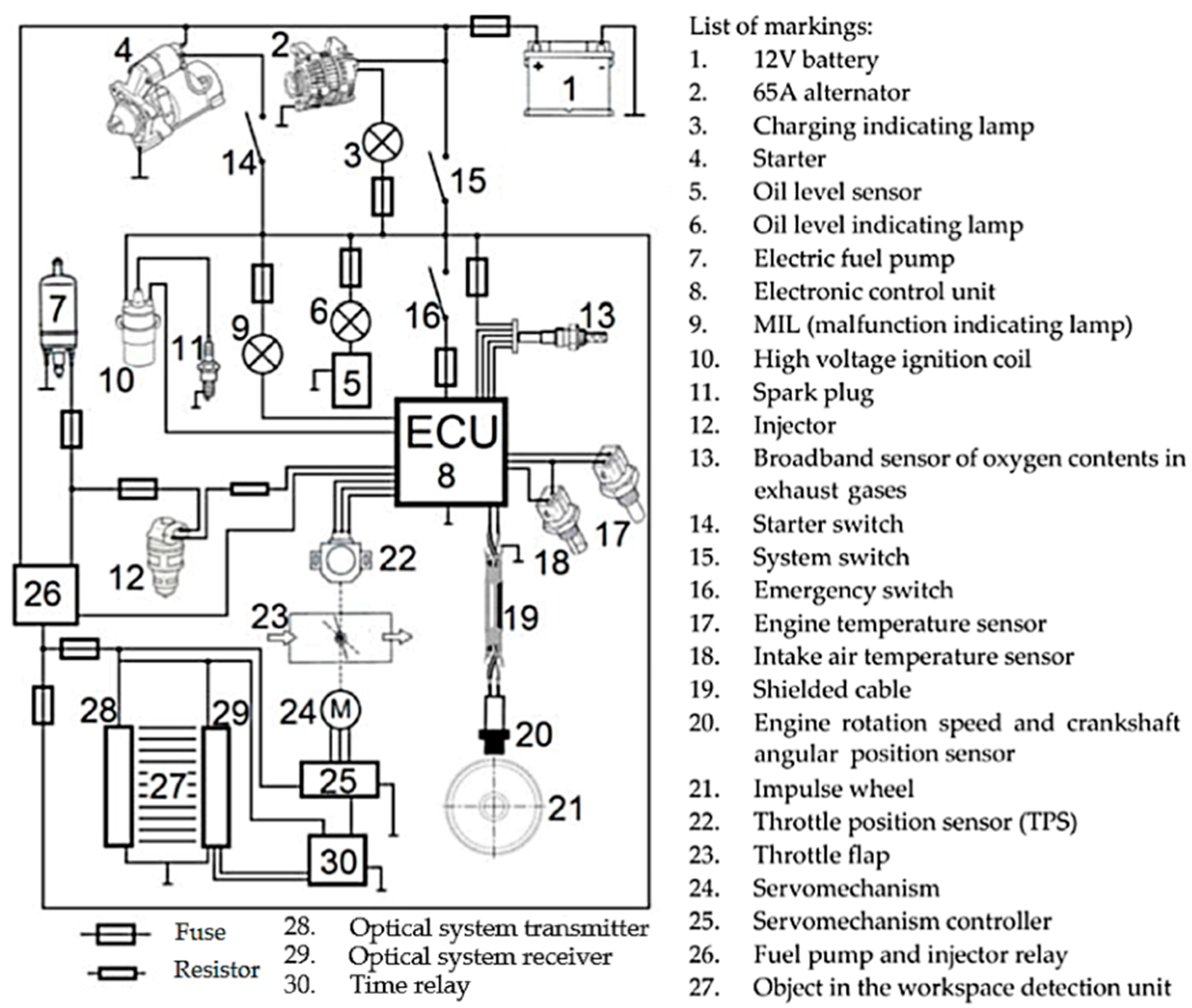
In the second configuration (B), the drive unit was modernized with a proprietary injection-ignition system developed by the authors [
39]. This is an indirect injection system with mixture composition regulation in closed-loop feedback and a variable advance angle. The system scheme is shown in
Figure 2 and its specification is presented in
Table 1. The detailed structure description is also available in scientific publications, for example [
35,
37,
39]. According to the review articles characterizing small combustion units for non-road applications made in 2018 [
33,
34], the developed system is characterized by an innovative approach for this group of engines. Commercial propulsion units considered to be one of the most innovative in this engine group (e.g., Honda iGX390 engine (American Honda Motor Company, Inc., Torrance, CA, United States)) are still equipped with a fuel delivery system as in a carburettor (no injection). In these solutions, only the throttle valve position is adjusted electronically. Despite this, the symbol “i” is introduced in the designation of the power unit (engine with the classic GX390 carburettor system), which could suggest an injection system. Scientists are still researching systems and components that reduce exhaust emissions from small engines. Mahmoudzadeh Andwari et al. in 2018 published simulation studies related to the development of a GDI (Gasoline Direct Injection) combustion chamber direct injection system for small engines [
36]. Whereas Niinikoski et al. in 2016 presented the test results of a system with electronic fuel injection (EFI) designed for small engines. In the developed system, the mixture composition was regulated on the basis of the throttle position and rotational speed signals [
38]. The system developed by the authors and tested in this article also includes the fuel-air mixture control signal from the intake air temperature sensor and the oxygen content sensor in exhaust gases, enabling closed-loop operation with feedback.
The third configuration (C) constitutes an upgrade of the injection-ignition system (B) with an adaptive system [
70]. The adaptive system adjusts the drive’s torque. When waiting for the branch, a chipper with such a drive operates at low speed (idle operation). Once the optical system detects a branch in the feed channel, the speed increases to allow the drive to work with the maximum power necessary to shred the branches. This is a patented solution (P. 423369) [
72]. The solution developed by the authors, as opposed to commercial ones, allows a reduction of the fuel consumption by regulating the rotational speed depending on the demand for torque during the shredding process. In a chipper with a classic speed control, the machine is idling at a high rotational speed. This makes it possible to achieve the maximum torque, the value of which depends on the load caused by the branch. This operation is characterized by a greater number of combustion cycles due to the higher rotational speed, and thus increases fuel consumption. A decrease in the rotational speed value during idling results in a reduction in the combustion cycles’ number and thus a reduction in fuel consumption. In such conditions, however, the engine characteristics have much less power; hence, in order to carry out shredding processes, it is necessary to detect the branches in the feed channel and increase the rotational speed again. The characteristics of the basic design are presented in
Table 1. The system was powered with 95 gasoline, whose characteristics are presented in
Table 2.
The branches of cherry plum (
Prunus cerasifera Ehrh. Beitr. Naturk. 4:17. 1789 (Gartenkalender 4:189-204. 1784)) were shredded. Their diameter was ca. 80 mm, length 3 m, and moisture content ca. about 25%. The humidity of selected branches was checked before and during the tests; the branches came from different places in the branch pile. The humidity test was carried out using a METTLER TOLEDO HR83 moisture analyzer (Mettler Toledo, Columbus, OH, United States). The test results for 30 samples are presented in
Table 3. Branches with such parameters take about 4.5 s to be chipped in a cylindrical chopper [
41]. Branches of similar diameters and lengths generated a similar machine load, which translated into a more uniform chipping time. Such branches should be considered typical. They put a heavy load on the machine. The tested specimens were representative of hardwood species in accordance with the Janka classification [
74]. The Janka hardness test measures the resistance of a sample of wood to denting and wear. It measures the force required to drive a steel drive of a 11.28-mm (0.444 in) diameter halfway into a sample of wood [
75,
76]. The branches were stashed at a distance of 2 m from the chipper and were fed by one experienced operator. During the test, based on signals from the optical system in the feed channel, the branch feeding frequency was recorded (position 3 in
Figure 1).
The woodchipper shown in
Figure 1 has three separate drive systems, all of them assembled at the same time (A, B, C). The drive unit was switched by changing the connection between the drive and the working unit using a variable gear with a V-belt. The adaptive system was turned on and off using specialized software in the injection system controller.
The measurements were performed under real operating conditions of the internal combustion engine. The tested machine performed a typical work cycle. During the test, for designs (A) and (B), the engine worked with high speed both during an idle run (about 3600 rpm) and under load. The use of an adaptive system increased the number of operating states. For this design (C), the idle speed was low (about 1800 rpm), with quick acceleration to high speed under load and the return to low speed. For each design, the test took 1 h. The concentration of harmful compounds and exhaust gas flow were measured continuously after the engine heat-up was completed. In the study, the start-up and warm-up times were omitted because the main research objective was to assess the influence of the adaptive system, which is used only during shredding. The tested machines had the air-fuel ratio (AFR) characteristic for them and were almost new (they worked for about 10 h). Exhaust emissions were tested using Axion RS+, a typical PEMS (portable emissions measurement system) from Global MRV.
Table 4 presents its technical specification. In the research, we analyzed the emissions of hydrocarbon (HC), carbon monoxide (CO), carbon dioxide (CO
2), and nitrogen oxides (NO
x). Based on the carbon balance, we determined fuel consumption according to Equation (1) [
77]:
where FC is the fuel consumption (dm
3·(100 km)
−1); HC, CO, CO
2 is the emission of harmful ingredients (g·km
−1); and
is the fuel density at 15 °C (g·(cm
3)
−1).
The device used measured the concentrations, which are expressed in vol % or in ppm, and on the basis of those values are expressed emissions that are more measurable. Such results enable the generated pollution amount mass estimation in selected areas and by specific machines. Measurement of the concentration and mass exhaust stream is a common method for determining toxic emissions and fuel consumption.
3. Results
For the three tested designs, the results show the emission of harmful compounds, such as HC (
Figure 3), CO (
Figure 4), CO
2 (
Figure 5), and NO
x (
Figure 6) together with fuel consumption during the shredding process (
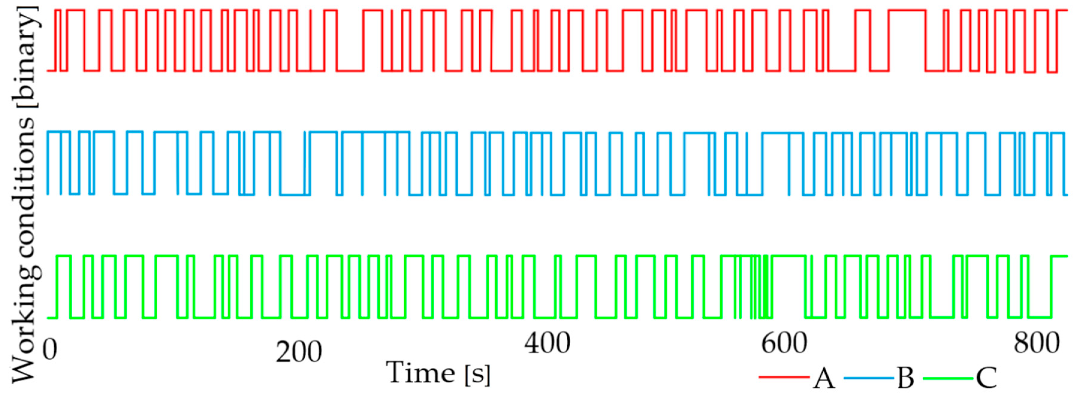
Figure 7) as a function of time: (A) The carburettor fuel supply system, (B) injector fuel supply system, and (C) injector fuel supply system equipped with an adaptive drive control system. To assess the shredding conditions, we also recorded the branch feeding frequency (
Figure 8).
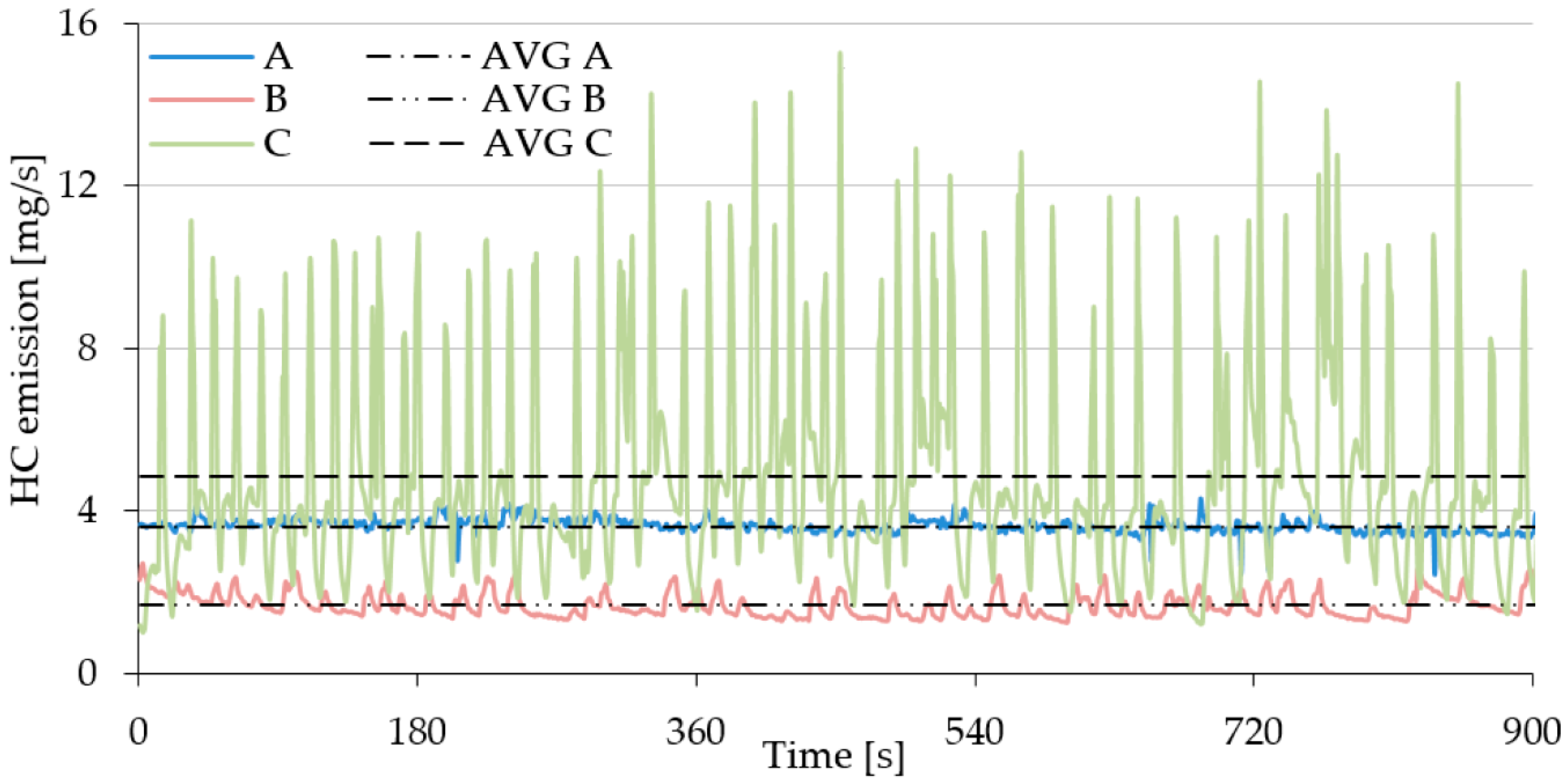
The characteristics shown in
Figure 3 indicate that the change in the engine load as a result of feeding a branch affects the HC emissions. Design C proved the most susceptible to changes in this parameter, and at the same time, it exhibited the highest emissions (
Figure 9). The HC emissions are due to the unburnt fuel particles in the exhaust gas. The operation of the adaptation system necessitates an increase in the rotational speed of the working unit when a branch is detected, which results in the enrichment of the fuel-air mixture. As seen in
Figure 9, the design necessitates modifications. It is necessary to focus on adjusting the mixture composition when the rotational speed changes from low to high because a large number of fuel particles are unburned. Design B, the injection system without an adaptive system, exhibited the lowest HC emissions (
Figure 9). Disturbances of the fuel-air mixture caused by changes in the engine load as a result of shredding increase HC emissions. Their level, however, does not exceed the emission generated by design A, which is least susceptible to changes of this parameter (
Figure 3).
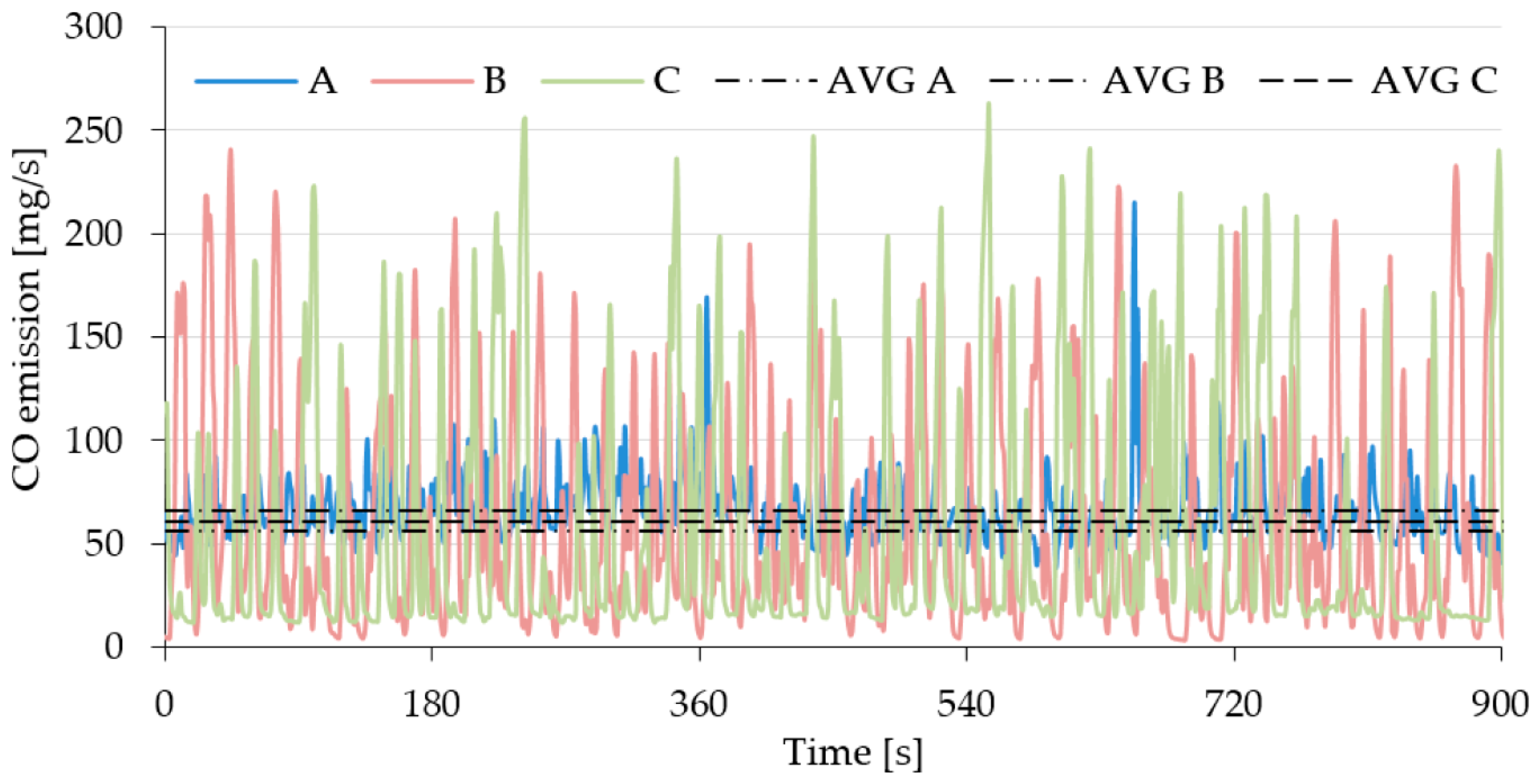
Carbon monoxide (CO) emissions are the product of the incomplete combustion of carbon, being a component of hydrocarbon fuel. CO emissions are unavoidable in internal combustion engines since the combustion chamber never allows for the complete combustion of carbon. Otherwise, only CO
2 could be found in the exhaust gas. The CO emission characteristics as a function of time show that designs B and C are prone to significant changes in CO emissions depending on the system load (
Figure 4), but the mean emission levels are lower than for design A (
Figure 9).
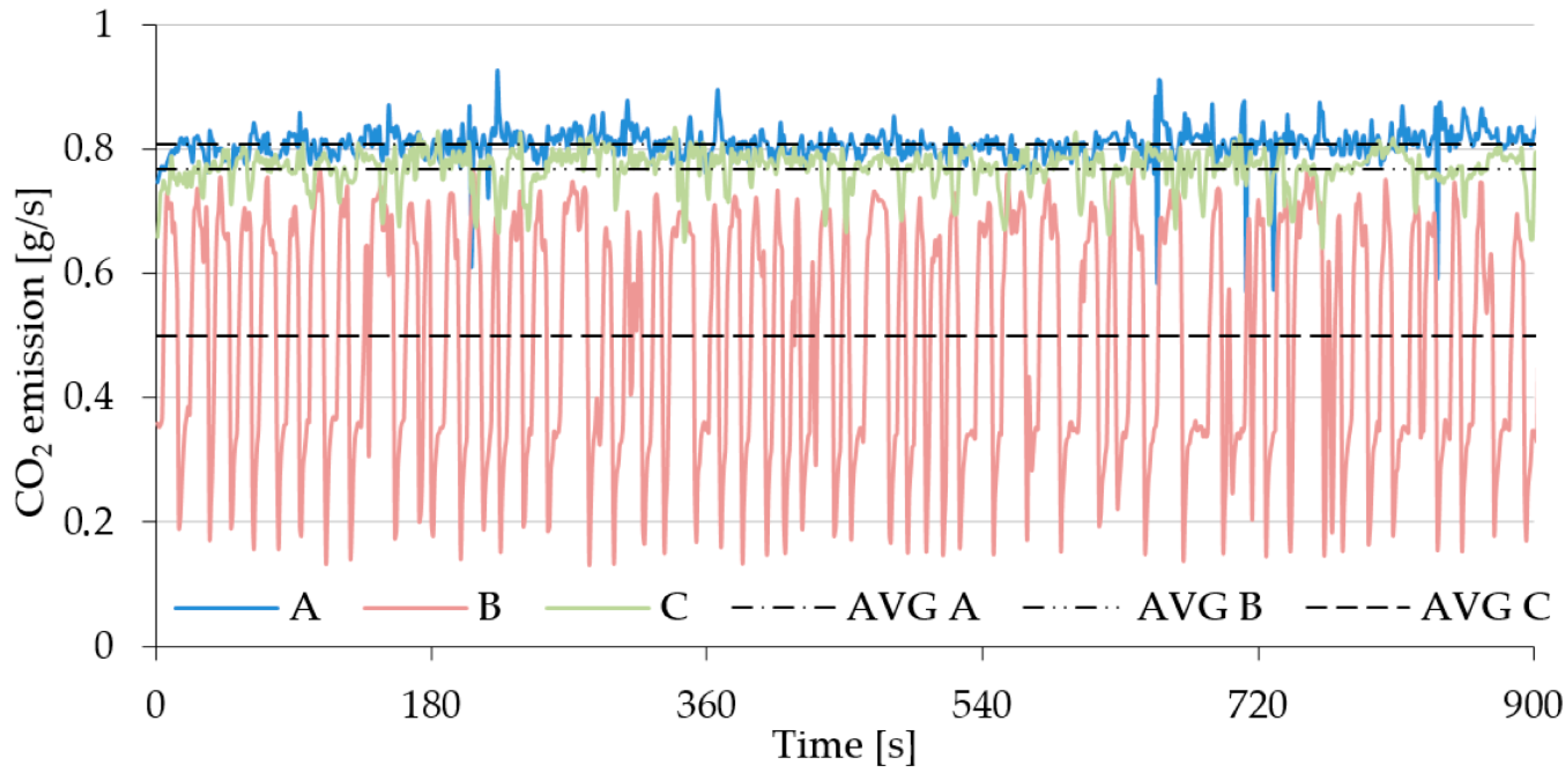
Carbon dioxide (CO
2) emissions result from the combustion of hydrocarbon fuels and they take place only when the mixture is completely burned. These emissions can be reduced by reducing fuel consumption or using low-carbon fuels. The CO
2 emission characteristics indicate that design B, equipped with an injection system, is the most susceptible to load changes. Significantly lower oscillations in this parameter were observed for the two remaining designs (
Figure 5). However, the mean CO
2 emission under test conditions is the lowest for design C, followed by design B. Design A, on the other hand, is characterized by the highest carbon dioxide emission (
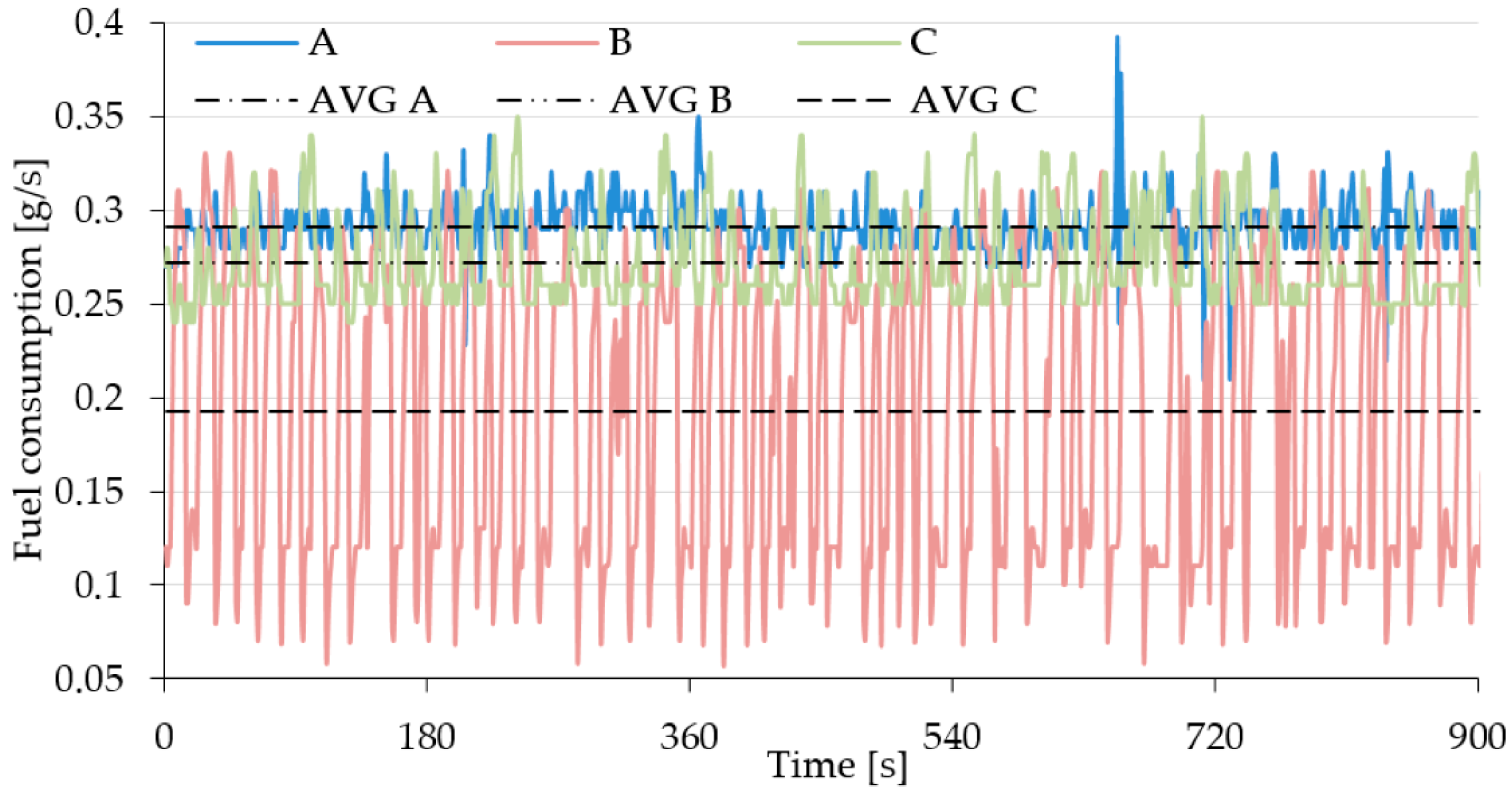
Figure 9). As fuel consumption is strongly linked to CO
2 emissions, the fuel consumption characteristics (
Figure 7) are very close to those for CO
2 emissions and similar conclusions can be drawn.
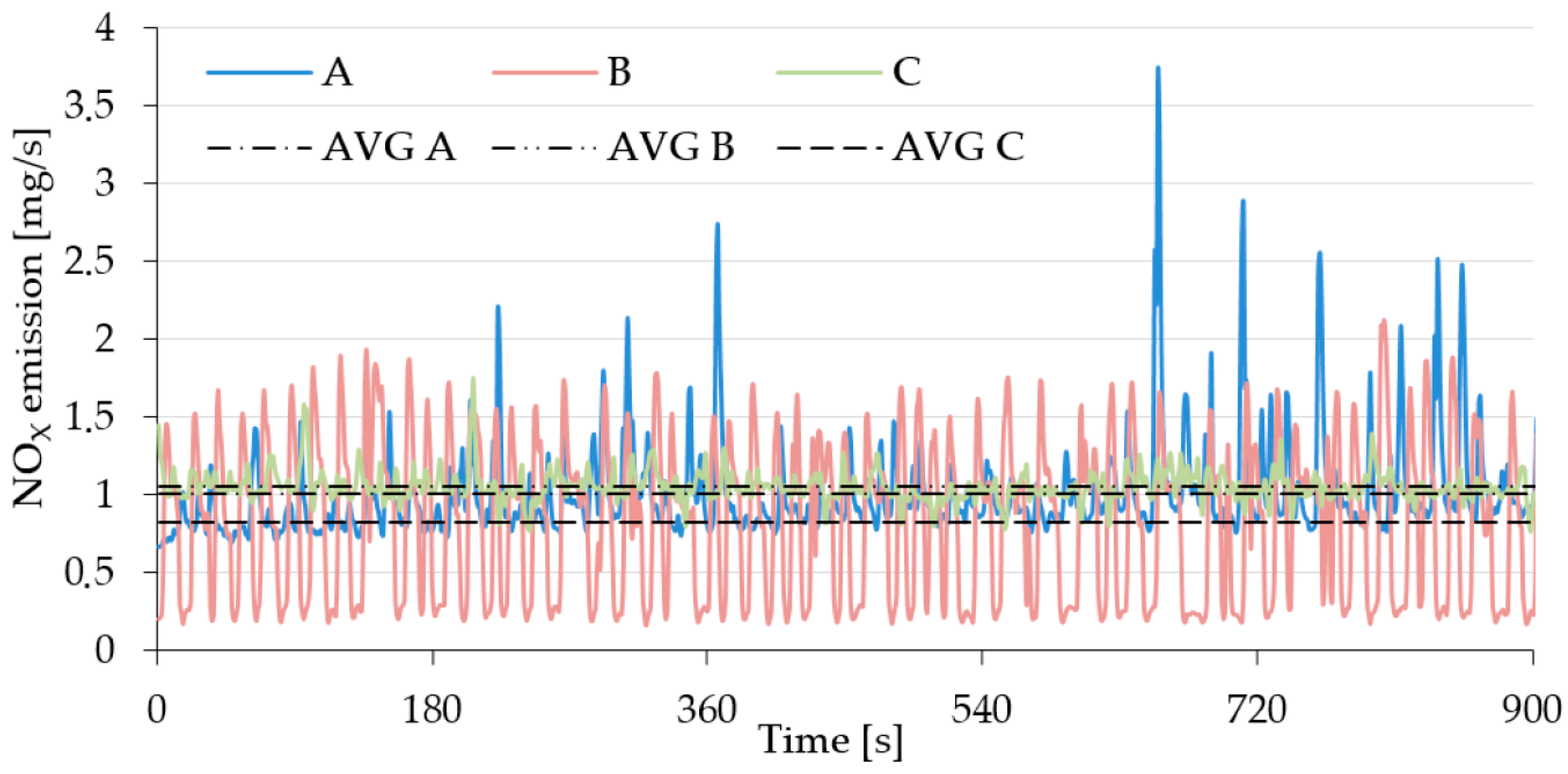
The characteristics of NO
x emissions are shown in
Figure 6. For nitrogen oxides (NO
x) to be created, the combustion temperature must be high and there must be free oxygen molecules. Hence, NO
x emissions are most often associated with the combustion of a lean mixture, i.e., with an excess of air over fuel compared to a stoichiometric mixture. In the graph shown in
Figure 6, you can see that design C was the least susceptible to changes in the NO
x emission characteristics. It also emitted the smallest amounts of this chemical compound under the tested operating conditions (
Figure 9). Design B was most susceptible to NO
x changes, where an increase in the engine load resulted in the mixture changing from stoichiometric to lean, which can be observed as a periodic increase in the NO
x value in the exhaust gas (
Figure 6).
Based on signals from optical sensors in the feeding channel (item 3 in
Figure 1), we determined the branch feeding frequency under specific measurement conditions (
Figure 8).
Table 5 shows the results. The branch feeding frequency in all samples was close to 4 min
−1.
The second parameter characterizing the chipping machines’ working conditions is the average mass flow rate of the shredded material. This value was determined on the basis of shredded branches’ mass measurements as a time function using a portable scale (Radlastplattform up to 1500 kg, meeting the requirements of ISO 9001). The mass flow rate measurement results depending on the different configurations of the machine are presented in
Table 6.
4. Discussion
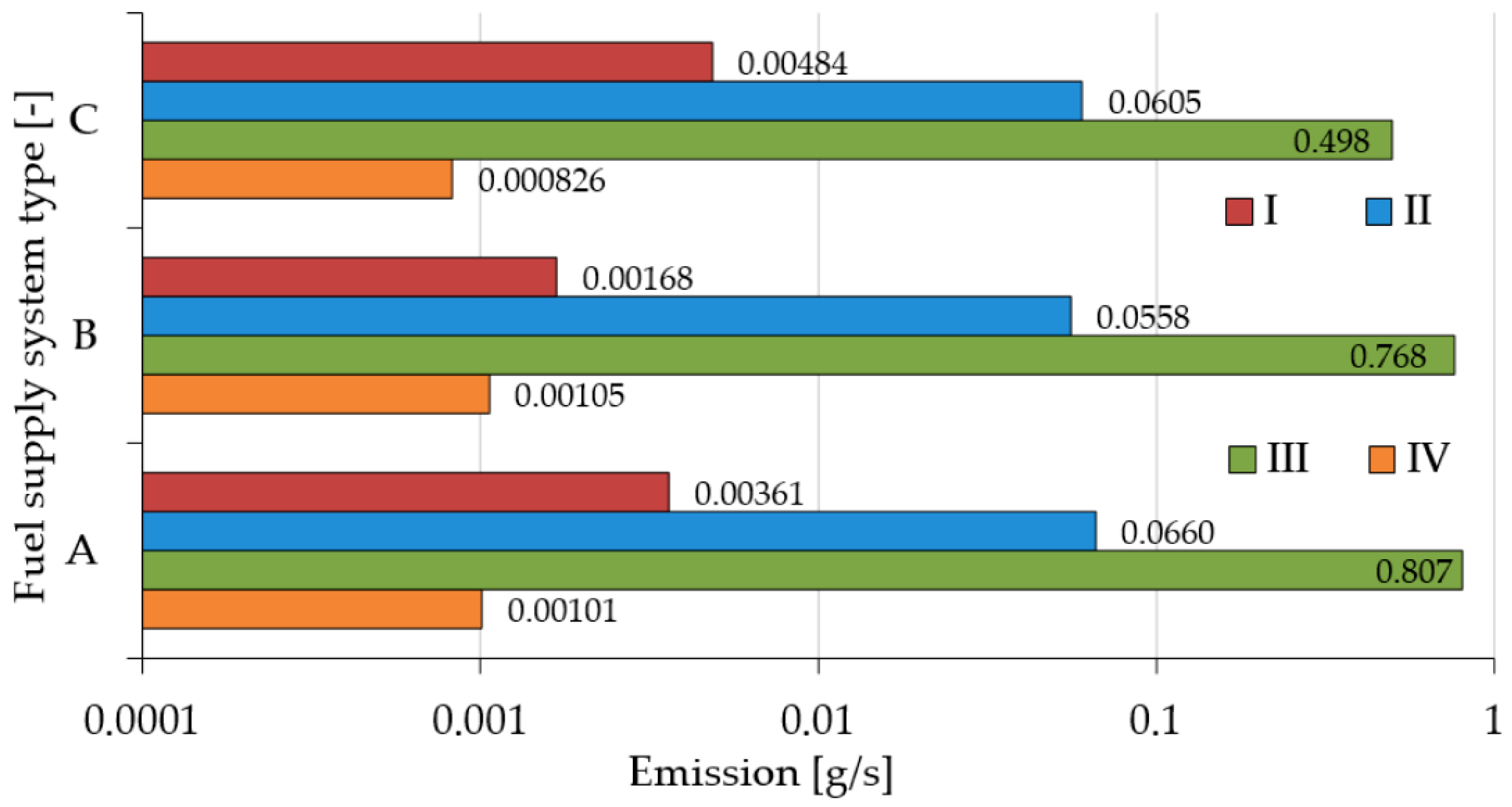
For efficient control of the drive unit and to evaluate the reaction of the tested design to changes in the operating conditions, it is important to measure the emission of the generated exhaust gas compounds as a function of time. The results may indicate areas that require improvements in the design. The results of the exhaust emission tests with their average values per specific time interval are equally important (
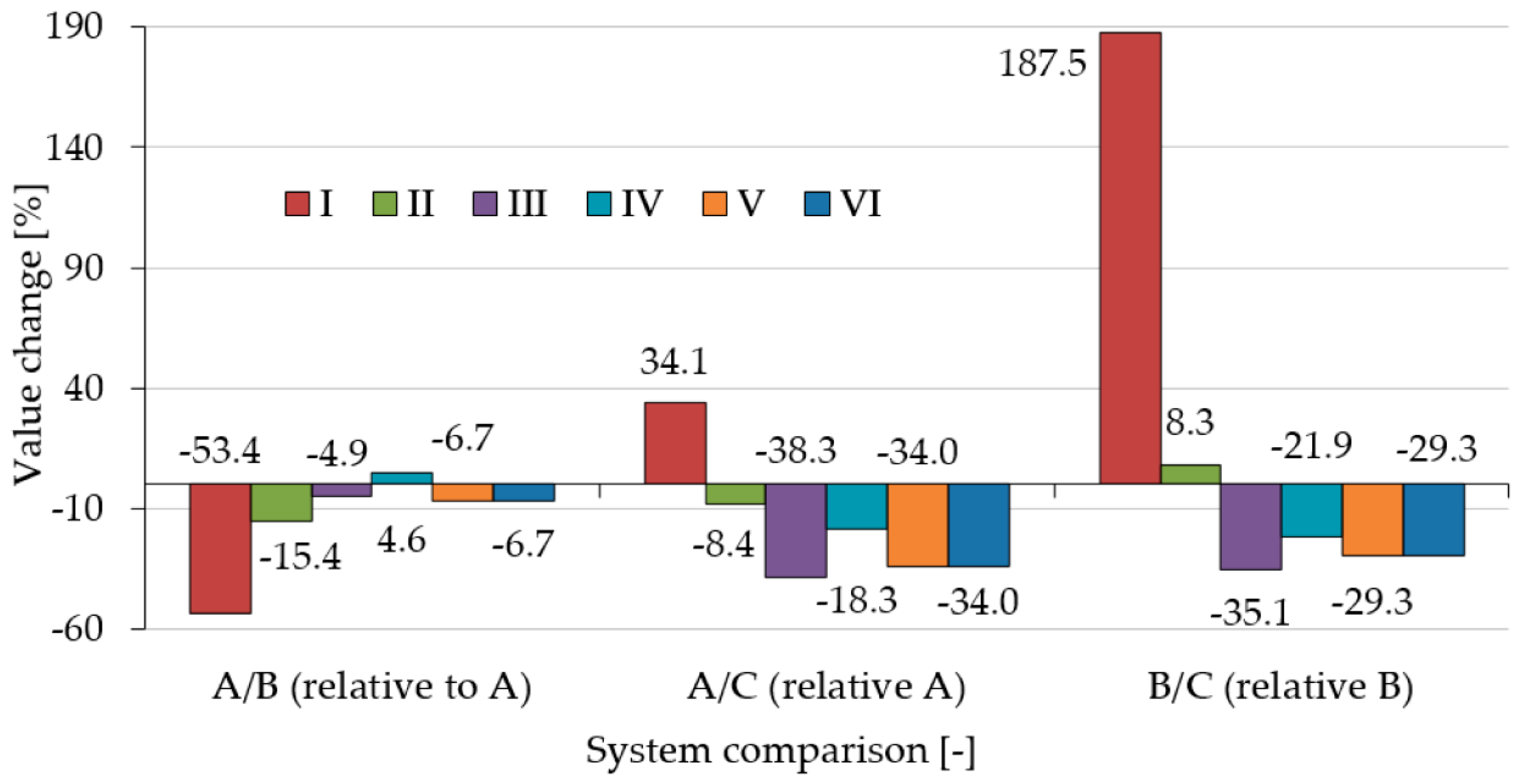
Figure 9). They enable a comparison of the data on selected designs and provide information on the impact of selected machines on global or local exhaust emissions. Comparison of the tested designs are presented (A, B, C) in
Figure 10, with the percentage comparison according to the following Equations (2)–(4):
where
is the selected value for the carburettor fuel supply system,
is the selected value for the injector fuel supply system, and
is the selected value for the injector fuel supply system equipped with an adaptive drive control system. Equations (2)–(4) are written in such a form that drops in the value are negative and increases in the value are positive.
The use of the injection system (B) significantly reduced the mass emissions of HC (53.4%), CO (15.4%), and CO
2 (4.9%) compared to the carburettor system design (A). On the other hand, adding an adaptive system (C) to design B contributed to the reduction of CO (8.4%), CO
2 (38.3%), and NO
x (18.3%) emissions. The factory design with the carburettor system (A) emitted less NO
x (4.6%) in relation to design B and less HC (34.1%) in relation to design C. The addition of an adaptive system (C) to the injection system (B) aimed at reducing fuel consumption by improving the adjustment of the machine operation mode (drive rotational speed) to the operation conditions, which was met [
70] and confirmed later in this article. However, the measurements of exhaust emissions showed a significant increase in the generation of HC (187.5%) and CO (8.7%). This is related to an increase in the rotational speed of the working unit by enrichment of the fuel-air mixture and incomplete combustion of carbon from fuel hydrocarbons. This shows that when increasing the rotational speed, the adaptive system can reduce the amount of fuel fed. The remaining emission measurements showed a reduction of CO
2 (35.1%) and NO
x (21.9%) in the exhaust gas. This suggests that the system burned less fuel and operated on a lean mixture for a shorter period. Based on the exhaust emissions, we can conclude that the adaptive system requires less hydrocarbon fuel and is a potentially beneficial solution but requires improvements in the mixture adjustment during engine speed changes to reduce HC emissions.
For example, HC, CO, and NO
x emissions can be reduced by using a three-function catalytic converter. Nitrogen oxides are reduced in catalytic reactions and decomposed into nitrogen and oxygen. The latter is used to oxidize carbon monoxide and hydrocarbons to carbon dioxide and water. The catalytic reactor requires appropriate thermodynamic conditions and maintenance of the stoichiometric properties of the fuel-air mixture to achieve high efficiency. Such a solution is beneficial for a feedback injection system design (such as design B), where mixture adjustment is set to a stoichiometric and is controlled and corrected. In 2008, Trzeciak demonstrated that a three-functional catalytic reactor should work mainly with a stoichiometric mixture because the reactor efficiency exceeds 90% in such conditions [
78]. Sets of catalytic reactors, which are a combination of three functional and oxidizing reactors arranged in series, are also used. An additional air stream is fed into the space between the reactors. In the first phase, such a system primarily reduces nitrogen oxides, and in the second phase, it oxidizes carbon oxides and hydrocarbons, which generates carbon dioxide and water. What is advantageous in this solution is that the fuel-air mixture does not need to be stoichiometric. Such a system may be preferred for carburettor (A) and carburettor (C) designs, where the rotational speed changes frequently. This constitutes a transient state of engine operation, and only in the steady state is the fuel-mixture control in the feedback (the steady state is characterized by a constant load and speed).
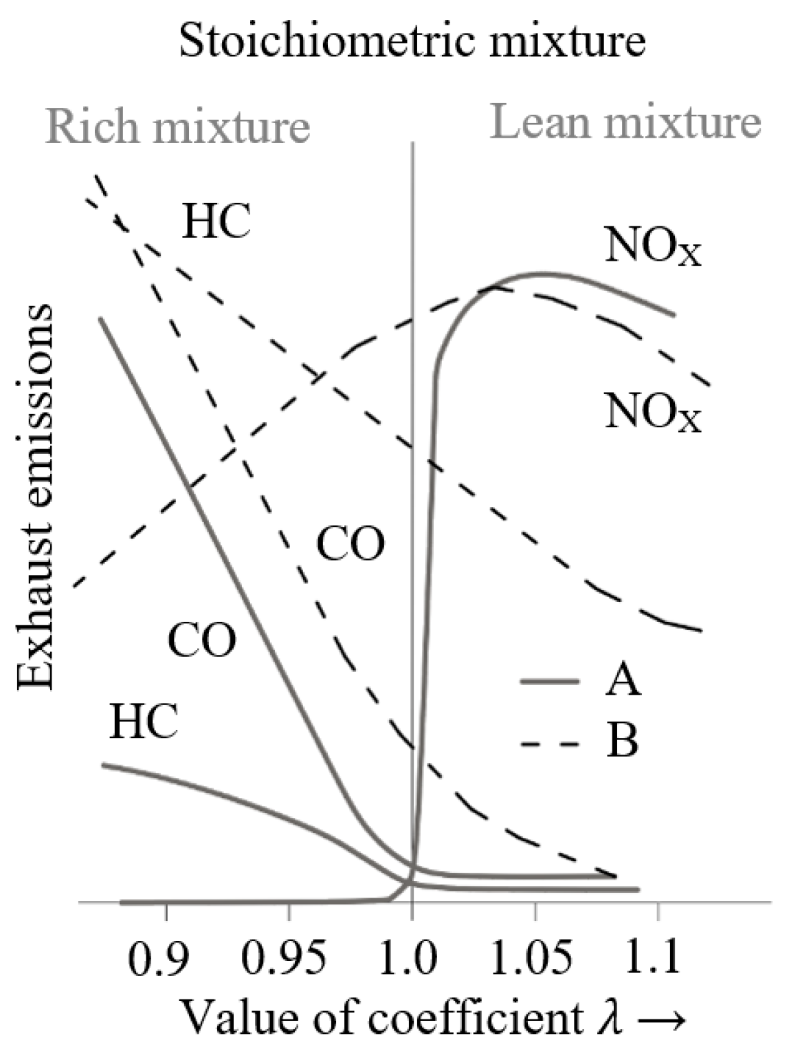
For design C, whose biggest disadvantage lies in high HC emission (resulting from a rich fuel-air mixture), it may be beneficial to use a three-functional catalytic reactor, since according to the characteristics presented in
Figure 11, such a system can significantly reduce HC emissions [
79].
Apart from the emission of harmful exhaust gas compounds, fuel consumption is also important when comparing the tested designs. Fuel consumption per hour of machine operation can be expressed in Equation (5) or Equation (6), as described by the following correlations:
where
Vp is the volume of fuel consumed during the measurement in [m
3],
is the fuel density under measurement conditions in [kg·(m
3)
−1],
t is the fuel consumption time during the measurement in [h], and
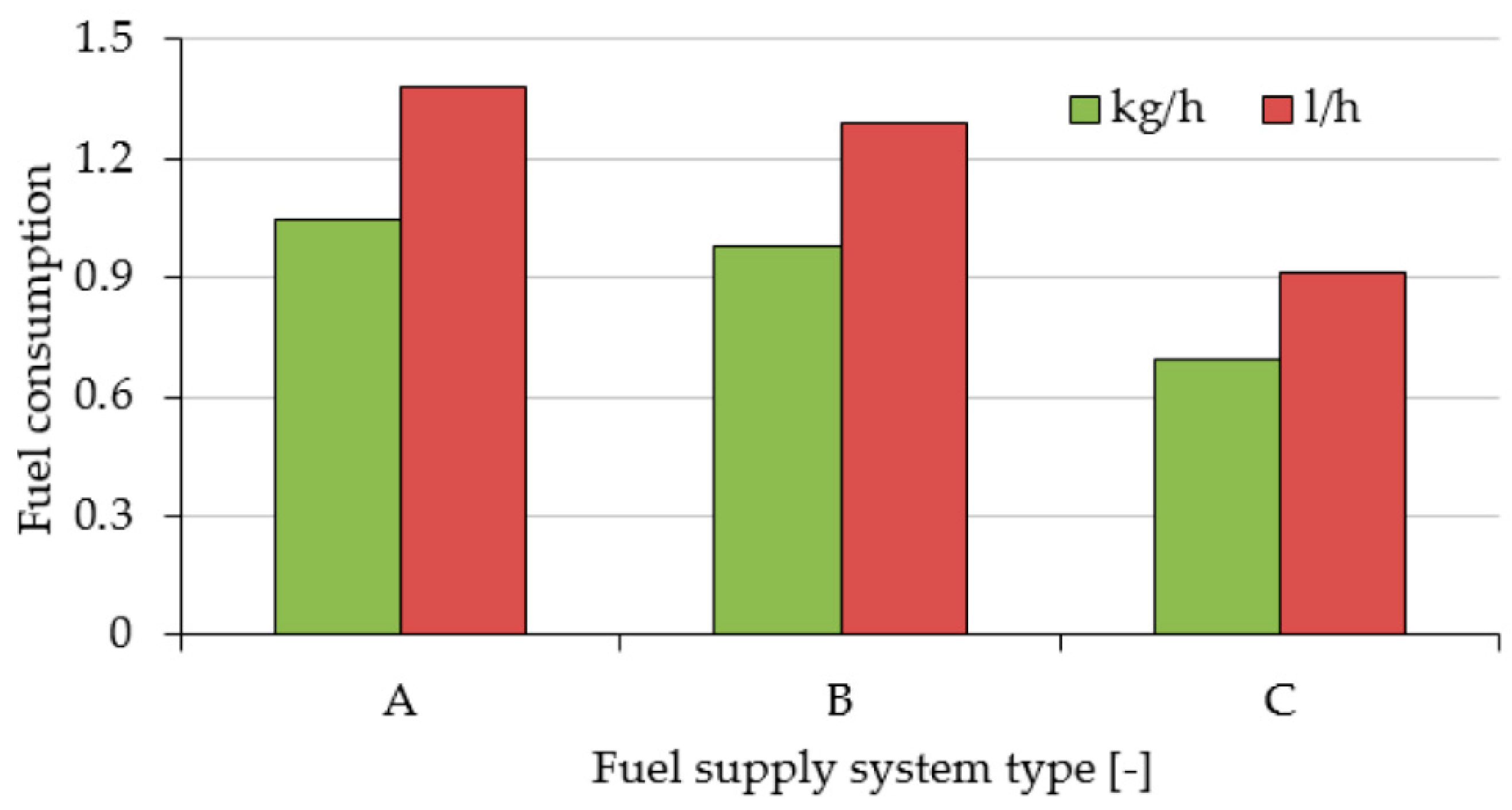
mp is the mass of fuel consumed during the measurement in [kg]. To facilitate analysis and comparison with other test results, we presented them in two units (
Figure 12).
Figure 10 presents a percentage comparison of the fuel consumption for selected designs according to Equations (2)–(4) (V graph). The use of the injection system (B) reduced fuel consumption by 6.7% from 1.38 to 1.29 l h
−1 when compared to the carburettor system (A). Modernization of the injection system (B) with an adaptive system (C) reduced fuel consumption by 34% from 1.38 to 0.91 l h
−1 compared to the carburettor system (A), and by 29.3% from 1.29 to 0.91 l h
−1 compared a non-modernized system (B).
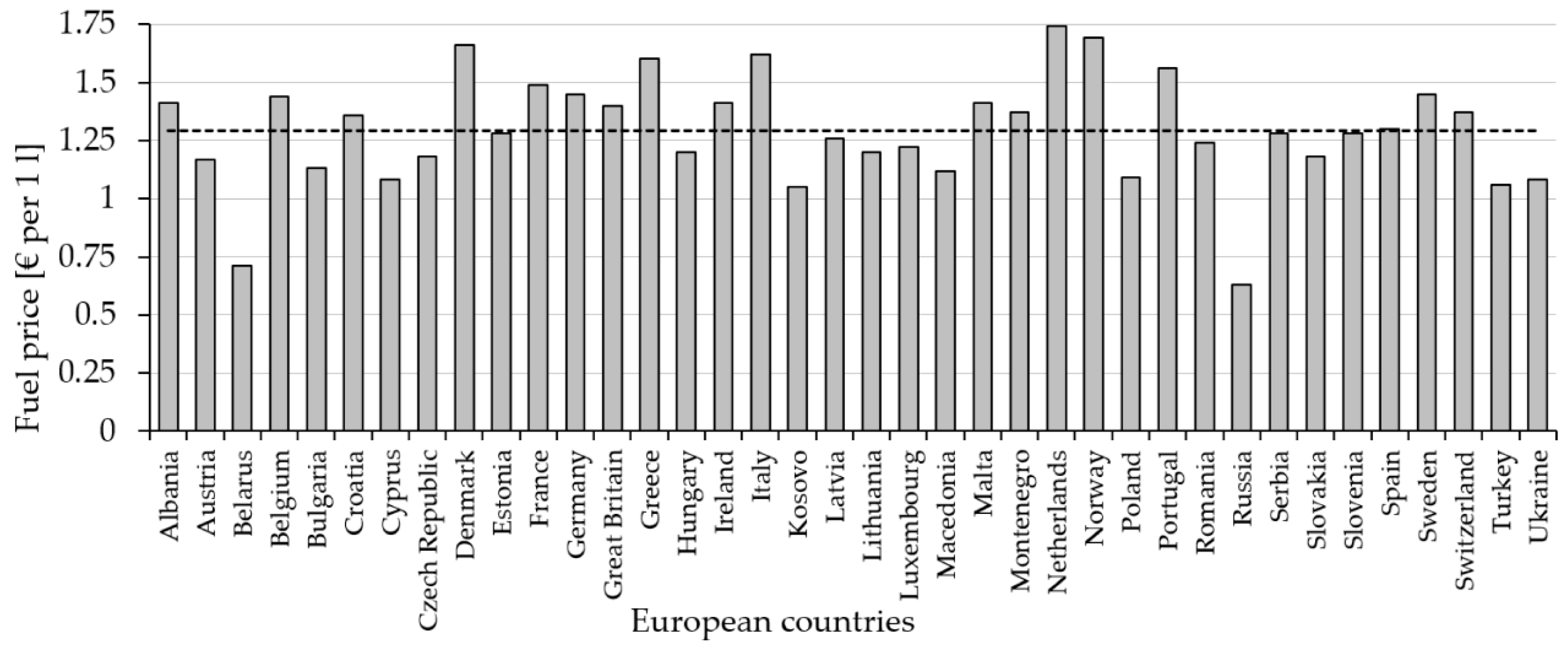
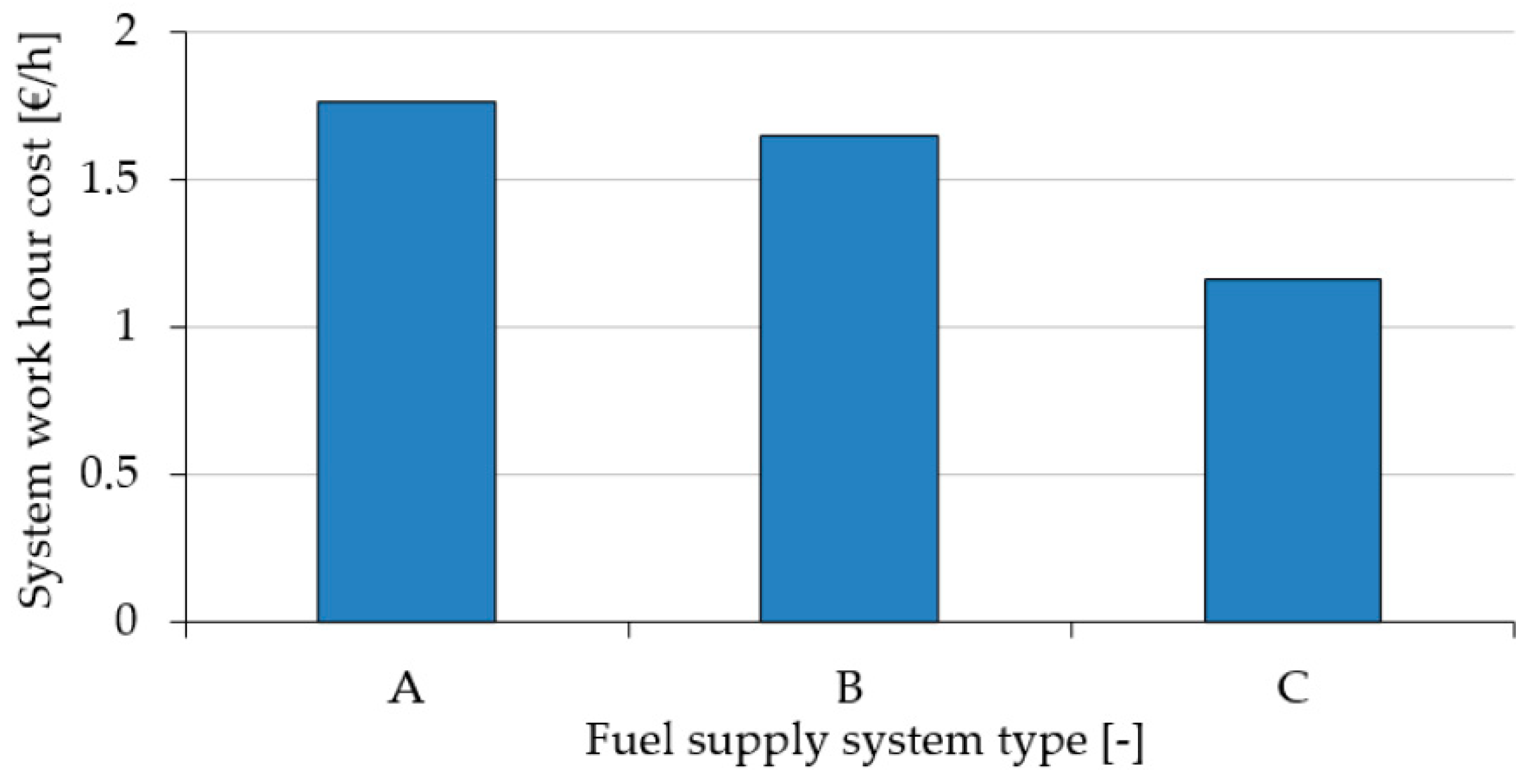
We also analyzed the operating costs of the cylindrical chopper resulting from fuel consumption. It is easier to estimate the operating costs with volumetric fuel consumption, as the tested fuel (gasoline 95) is widely sold in liters across the EU. A liter of 95 lead-free petrol at 15 °C weighs an average of 0.76 kg (measurement of compliance with PN-EN ISO 12185 and PE-EN ISO 3675). The fuel consumption values during chipper operation hours are shown in
Figure 12. Fuel prices depend on many variables and change daily. Moreover, they vary from country to country or even across regions [
80,
81,
82]. We established a mean price in EUR per 1 L of fuel in Europe as of 10 January 2020 (
Figure 13). The mean fuel price was 1.28€·l
−1. On this basis, we determined that the cost of fuel consumption in Europe per hour of chipper operation, depending on the type of the power unit, ranges from 1.77 (design A) to 1.17€·h
−1 (design C), as shown in
Figure 14.
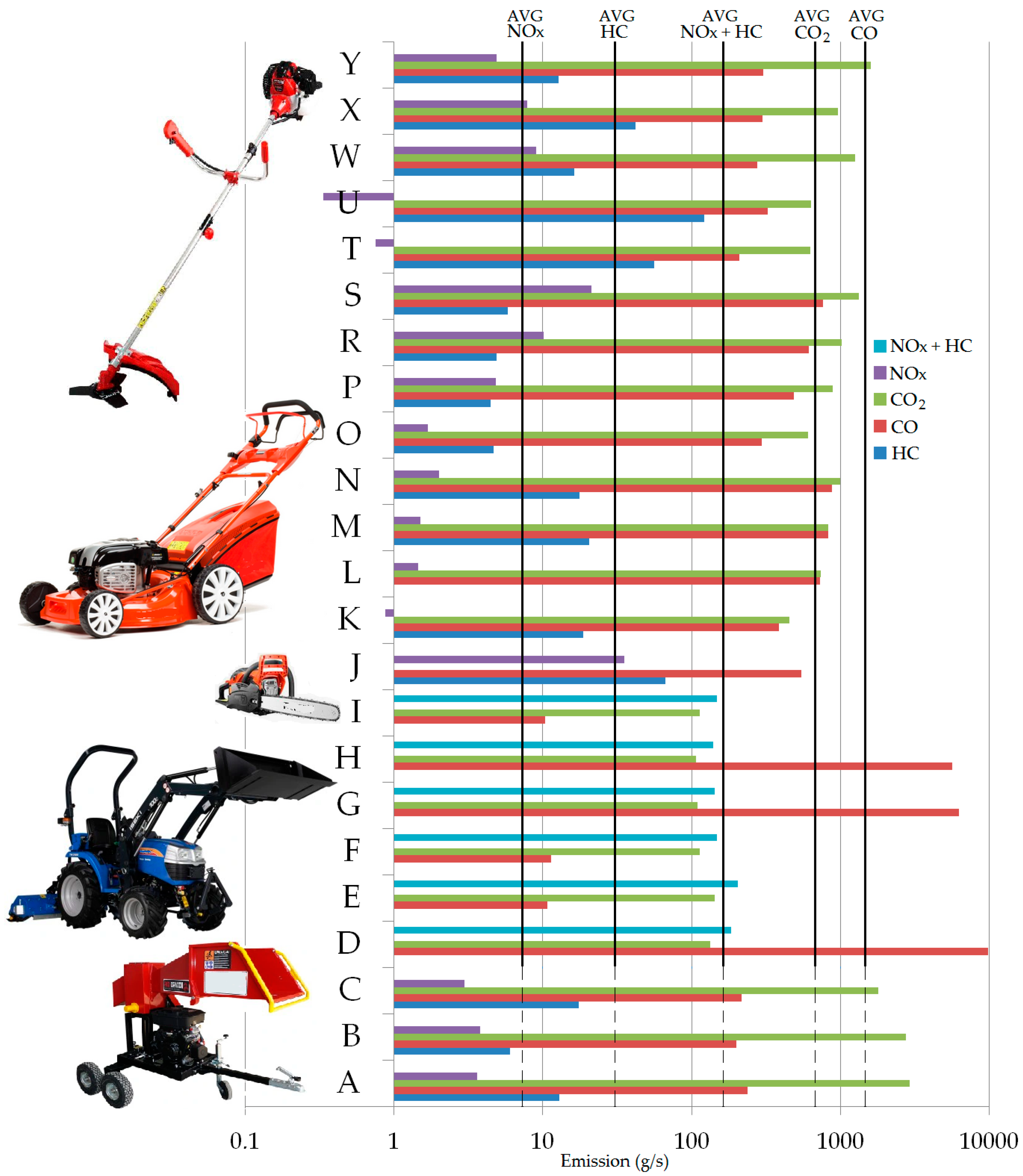
Figure 15 presents a comparison of the exhaust emissions from machines that are used for plant management in urbanized areas, e.g., a gasoline sawing machine [
83], a lawnmower [
56], a gasoline mower [
55], tractor for spraying weeds, spraying trees with insecticide preparations, or soil recultivation [
57].
Exhaust gas emission is most often expressed in g·km
−1 or g·(kWh)
−1. The data collected in the literature review refer to various physical quantities. To make them comparable, it is necessary to transform them. Thus, exhaust emissions (
) expressed in [g h
−1] were determined based on the nominal power of the machine
given in kW and the exhaust emissions depending on the power of the machine
expressed in g·(kWh)
−1. For this purpose, we used the relationship defined by Equation (7):
In other words, the procedure described for determining the value assumes an hour of operation of the machine at full power.
Regardless of the applied fuel supply system, exhaust fume emissions from a cylindrical chipper with a power of about 9.5 kW are characterized by lower hourly emissions of NOx, HC, and CO than the average hourly emission for machines used in agriculture, horticulture, or fruit growing in urbanized areas. It is, however, characterized by higher CO2 emission than the average hourly emission in these machines.
Fuel consumption in chippers used for shredding branches with a diameter of up to 100 mm under actual operating conditions ranges from 0.91 to 1.38 l h
−1. For comparison, chippers on biomass plantations with power from 103 to 420 kW consume from 4.36 to 59.52 l h
−1 [
84] fuel (diesel).
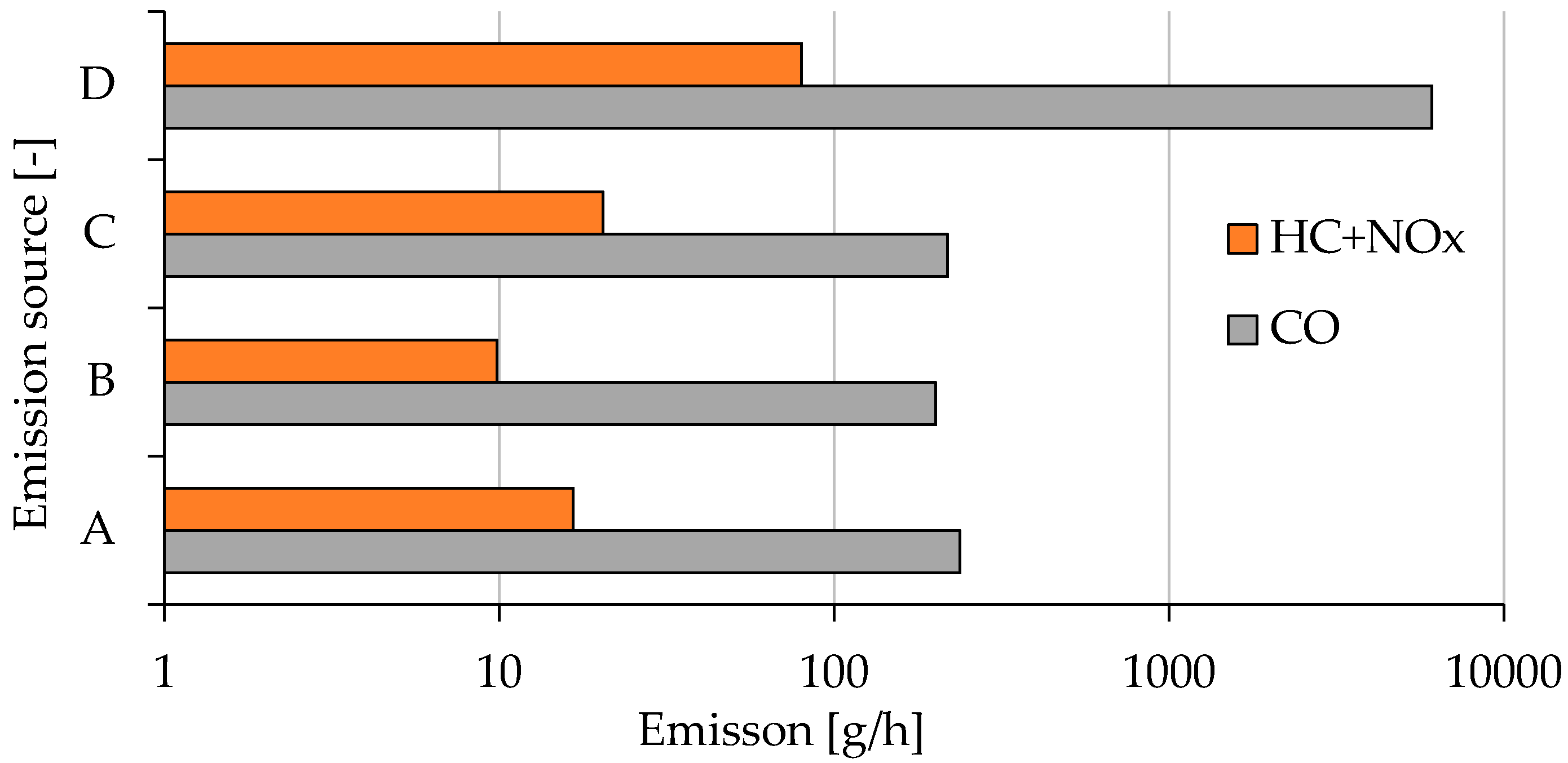
The permissible limits for the harmful compounds in exhaust gas emission for the tested group of propulsion units according to the provisions in force in the European Union from 2019 are presented in
Table 7 [
21]. These engines are subject to the NRS-vr/vi-1b category, according to Stage V emission standards for non-handheld SI engines below 56 kW (NRS).
Therefore, a comparison of permissible emissions and approximate emissions from the tested engines was made (
Table 8). The results indicate that the drives in question do not exceed the limits allowed in the European Union during one hour of operation (
Figure 16). However, it should be borne in mind that the engines tested in real operating conditions were not characterized by the maximum load.
5. Conclusions
Limiting air emissions is important for all machines. It is particularly important in areas where air pollution exceeds the concentration levels allowable for human life and health. Such areas mainly include urbanized areas, where any reduction of air pollutant emissions matters. One of the ways to reduce them is through innovation in low-power engines of woodchippers used for shredding branches in urbanized areas. In Europe, spark ignition combustion engines with power up to 19 kW are subject to relatively liberal regulations [
20,
21], allowing for the use of drives with carburettor power systems [
33], which have been discontinued in vehicles since the 1990s in favor of injection systems [
85]. The research discussed in this paper showed that a commercial drive unit (with a capacity of 389 cm
3 and power of 9.5 kW) used in the shredding machine consumes 6.7% more fuel than the drive unit with an injection system developed by us. Moreover, we developed an adaptation system [
70] designed for the injection system (patent application P. 423369 [
72]), which allows a reduction of fuel consumption in real conditions of use by 34% compared to a commercial unit. The systems are characterized by limitation of the emissions of exhaust gas compounds related to carbon combustion (CO, CO
2, NO
x), but they exhibit increased emission of hydrocarbons (HC), which is indicative of incomplete combustion of fuel particles and, what follows, from the fuel mixture being too rich in some areas of work. However, we envisage solving this problem by improving the control of the mixture composition, using exhaust gas treatment systems, or using fuels with lower carbon content. Such solutions may be used commercially in the future. However, this would require the cooperation of legislative bodies and engineers, as without the legislative pressure, manufacturers will not use more expensive solutions to reduce emissions. Depending on the drive unit design, an hour of operation of the tested machine resulted in the following emissions: HC 0.013 kg h
−1, CO 0.24 kg h
−1, CO
2 2.91 kg h
−1, and NO
x 0.0036 kg h
−1 (design with carburettor system); HC 0.0061 kg h
−1, CO 0.20 kg h
−1, CO
2 2.77 kg h
−1, and NO
x 0.0038 kg h
−1 (design with injection system); and HC 0.017 kg h
−1, CO 0.22 kg h
−1, CO
2 1.79 kg h
−1, and NO
x 0.0030 kg h
−1 (design with injection and adaptive systems). Reducing the energy consumption of the plant shredding processes [
86] is still a valid scientific problem that translates directly into the quality of the natural environment and human health.
The research presented in the paper is in line with the global trend of measurements in real operating conditions; therefore, according to the authors, they should be continued. For the studied small engine category, measurements in real operating conditions are at an early stage of development. In the future, all experience gained regarding the test method can be used to develop testing procedures, including approval ones. Further research is planned for the cylinder woodchipper drive, including the use of alternative fuels, bio fuels, compressed natural gas (CNG), and liquefied petroleum gas (LPG). In addition, experiments for devices’ various loads are also planned, e.g., from wood of different hardness or humidity.
6. Patents
The design solution described in this paper is subject to a patent application in Poland: Ł. Warguła, P. Krawiec, K.J. Waluś, 2017: The system and method of speed control of woodchipper drives (original text in Polish: Układ i sposób sterowania prędkością obrotową napędu rębaka do drewna), Poznan University of Technology, Poznań, Poland, application number: P. 423369, date of filing 06.11.2017.
In addition, the design developed on the basis of the above-mentioned patent application was rewarded with a silver medal at the XII International Invention and Innovation Show INTARG, 4–5.06.2019, Katowice, Poland, and a silver medal at the International Warsaw Invention Show IWIS 14–16.10.2019, Warsaw, Poland.

 ,
, 


