Article

Hydrokinetic Power Conversion Using Vortex-Induced Oscillation with Cubic Restoring Force

1
College of Mechanical and Electrical Engineering, Harbin Engineering University, Harbin 150001, China
2
Marine Renewable Energy Laboratory, Department of Naval Architecture & Marine Engineering, University of Michigan, 2600 Draper Road, Ann Arbor, MI 48109-2145, USA
3
Intern, Detroit Country Day—Upper School, 22305 W 13 Mile Rd, Beverly Hills, MI 48025, USA
4
Mathematical Sciences Department, Worcester Polytechnic Institute, Worcester, MA 01609, USA
5
Vortex Hydro Energy, Ann Arbor, MI 48108, USA
6
College of Aerospace and Civil Engineering, Harbin Engineering University, Harbin 150001, China
*
Author to whom correspondence should be addressed.
Energies 2020, 13(12), 3283; https://doi.org/10.3390/en13123283
Submission received: 30 April 2020 / Revised: 5 June 2020 / Accepted: 12 June 2020 / Published: 25 June 2020
(This article belongs to the Special Issue Hydrokinetic Energy Conversion: Technology, Research, and Outlook)

Abstract

:
A cubic-spring restoring function with high-deformation stiffening is introduced to passively improve the harnessed marine hydrokinetic power by using flow-induced oscillations/vibrations (FIO/V) of a cylinder. In these FIO/V experiments, a smooth, rigid, single-cylinder on elastic end-supports is tested at Reynolds numbers ranging from 24,000 < Re < 120,000. The parameters of the tested current energy converter (CEC) are cubic stiffness and linear damping. Using the second generation of digital virtual spring-damping (Vck) controller developed by the Marine Renewable Energy Laboratory (MRELab), the cubic modeling of the oscillator stiffness is tested. Experimental results show the influence of the parameter variation on the amplitude, frequency, energy conversion, energy efficiency, and power of the converter. All experiments are conducted in the low turbulence-free surface water (LTFSW) channel of the MRELab of the University of Michigan. The main conclusions are: (1) The nonlinearity in the cubic oscillator is an effective way to extend the vortex-induced vibration (VIV) upper branch, which results in higher harnessing power and efficiency compared to the linear stiffness cylinder converter. (2) Compared to the linear converter, the overall power increase is substantial. The nonlinear power optimum, occurring at the end of the VIV upper branch, is 63% higher than its linear counterpart. (3) The cubic stiffness converter with low harnessing damping achieves consistently good performance in all the VIV regions because of the hardening restoring force, especially at higher flow velocity.

1. Introduction

Fluid-structure interaction is a phenomenon occurring widely in marine applications, particularly to long cylindrical structures with bluff cross-section, such as risers and pipelines in transverse flow. This results in flow-induced oscillation/vibration (FIO/V) of the structure [1,2,3,4]. The two most common FIOs are vortex-induced vibration (VIV) and galloping. Depending on the natural frequency and damping of the structure those two phenomena may also coexist. FIO/V may cause first-shot or fatigue failure or collision with nearby structures; thus, in most marine applications, extensive analysis and testing are performed to suppress them.
VIV is typically interpreted: (a) as lock-in between oscillations and vortex shedding [3,5]; or (b) as nonlinear resonance between vortex shedding and variable natural frequency using variable added mass [6]. A recent development has revealed the existence of an eigen-relation at the interface between fluid and structure, which explains all experimental observations over the past 70 years and provides analytical expressions for the major force components and their phases with an outstanding agreement with experimental data [1]. This theory is valid in galloping as well. Further, VIV is a self-limiting phenomenon. As the flow passes a non-streamlined elastic cylinder or prism, the two shear layers roll up generating vortices which shed alternately on the corresponding side of the cylinder. This results in alternating lift perpendicularly to the flow, which coupled with the restoring/stiffness force of the oscillator, results in VIV. After Leonardo da Vinci first discovered VIV in 1504, many researchers began to carry out experimental and numerical studies to understand the underlying mechanics and fluid-structure interaction of this phenomenon. Although the amplitude of VIV is self-limiting, the phenomenon is highly destructive because of the broad range of synchronization (lock-in) between vortex shedding and body oscillation.
For the natural frequency of the oscillating cylinder, Lee and Bernitsas 2011 [7] have shown how the onset of the regions of VIV shift (Figure 1) with respect to the flow velocity. The spring-stiffness is one of the key parameters when designing an FIO/V-based converter such as VIVACE [8]. For a lower stiffness linear oscillator, the initial branch starts at lower flow velocity and the upper branch also ends earlier. At higher stiffness, the upper branch shifts to much higher flow velocity but the initial oscillation velocity is lower. It was proven that the higher the natural frequency of the converter, the more energy can be obtained in the VIV upper branch. One of the promising directions of research is to make the natural frequency of the oscillator vary nonlinearly [9,10]; for example, by designing the spring-stiffness to be position-dependent.
In general, nonlinearities in the oscillator can change its natural frequency [11]. Consequently, enhancement of the harnessed power can be achieved via stiffness [10,12,13]. In previous research on cubic stiffness, Mackowski and Williamson (2013) demonstrated that the upper branch of VIV can be extended, resulting in the extension to a broad range of flow velocities. Several research publications [14,15,16,17] demonstrated that better performance, or wider range, in terms of the energy extraction can be achieved from a generic wider spectrum vibration via a bi-stable oscillator. In an earlier publication [10], a cylinder oscillator with cubic stiffness and a locally rough cylinder with PTC (passive turbulence control = localized turbulence stimulation) was tested. It studied the effect of cubic stiffness on the galloping region (higher flow speed), and the transition from VIV to galloping. In the latter, the power of the PTC-cylinder drops significantly.
To overcome the shortcomings of the linear damping converter and obtain more energy and higher efficiency, the cubic stiffness function of a single-smooth-cylinder converter is introduced in this study. The underlying concept of this CEC is fluid-structure interaction (FSI), which is based on the coupling effect of the converter natural frequency and alternating lift due to vortex shedding. This research focuses is on the VIV region. Theoretically, the hardening of the cubic stiffness can extend the upper branch in VIV, which has high energy conversion efficiency. This phenomenon does not occur in the PTC-cylinder in [9]. The range of flow speed in the experiments is 0.34 m/s < U < 1.33 m/s (24,000 < Re < 120,000). It falls in the TrLS3 flow region and is close to the range of operation of small commercial scale converters.
The test equipment (including the emulated spring and the oscillator) and the cubic stiffness are presented in Section 2 and Section 3, respectively. The mathematical model of efficiency and energy acquisition is established in Section 4. The experimental results of the oscillatory response and the harnessed efficiency and energy are discussed in Section 5. Conclusions are drawn in Section 6.

2. Test Apparatus

The experimental facility and the embedded virtual spring-damping controller that enables correct modeling of the cubic stiffness oscillator with a systematic variation of the harnessing damping are introduced in this section.

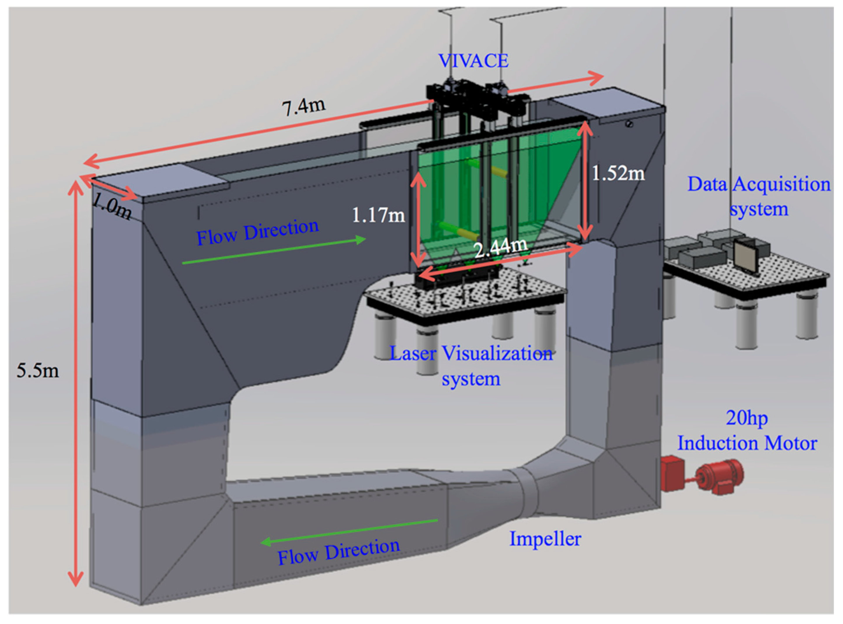
2.1. The Ltfsw Channel

The nonlinear stiffness tests are conducted in the low turbulence-free surface water (LTFSW) channel of MRELab of the University of Michigan (Figure 2). The Channel recirculates 37,854 L (10,000 gallons) of water of selected temperature with an impeller driven by an induction motor (20 hp) at speeds up to 1.4 m/s.
The test section is made of transparent acrylic glass, 2.44 m long, 1.0 m wide, and 1.52 m high. The water depth in this study was 1.17 m as shown in Figure 2. The flow around the cylinder is studied under the action of two 5 W argon lasers and 100 μm alumina particles.

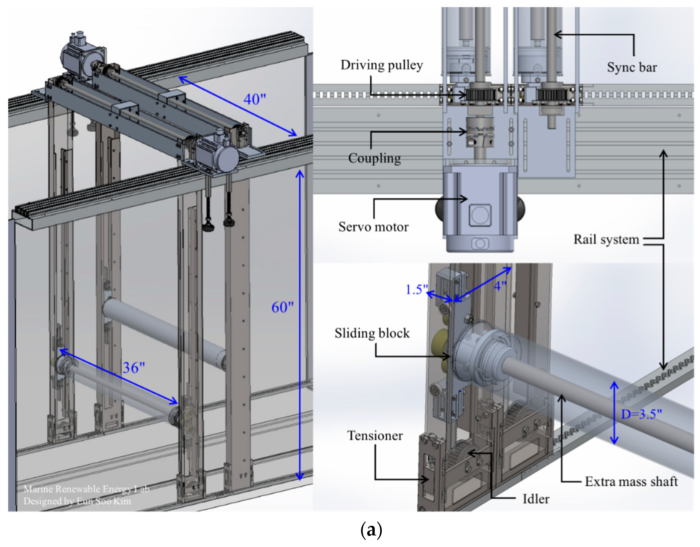
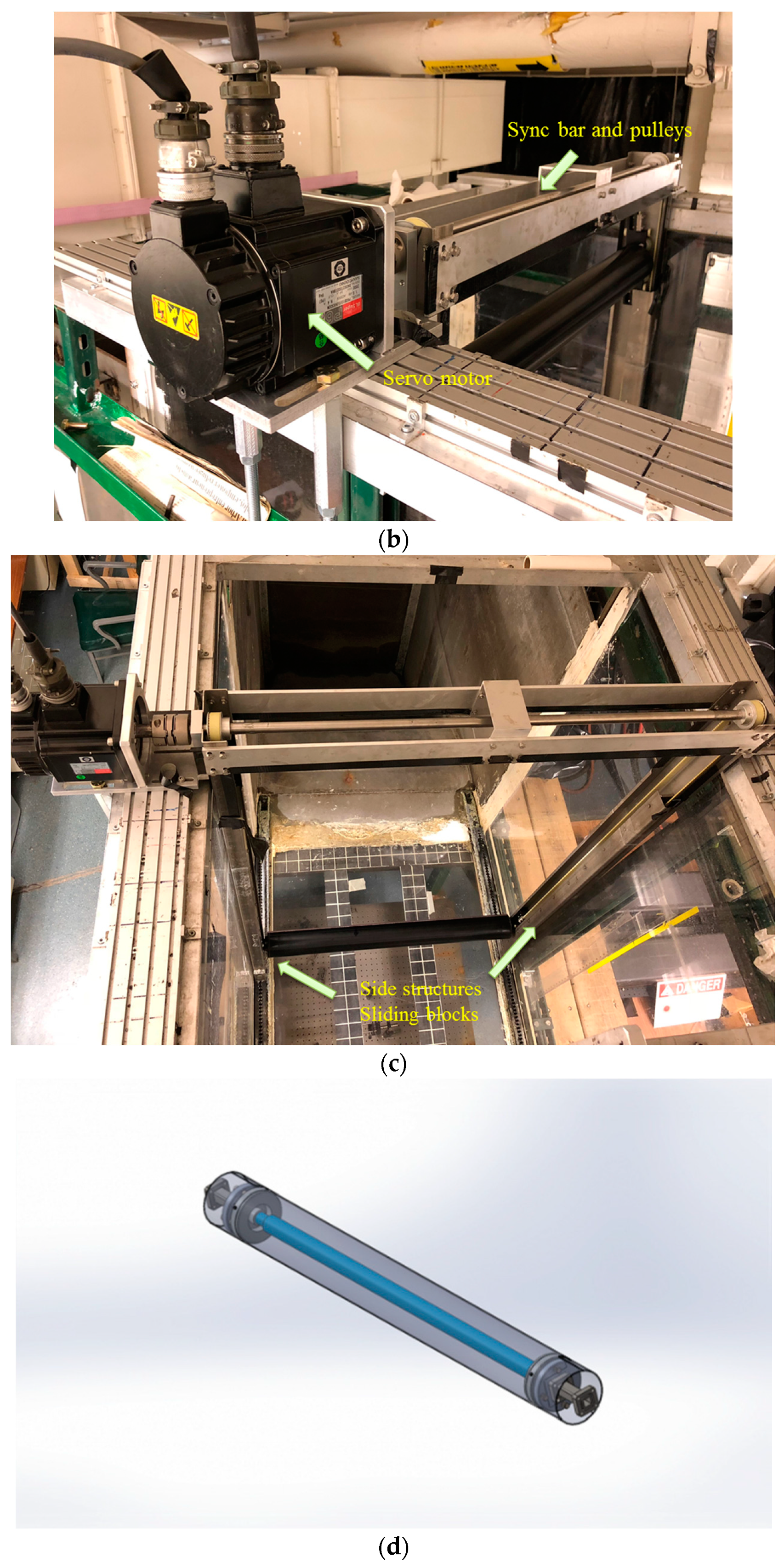
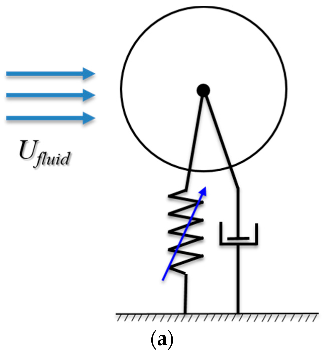
2.2. Oscillator Emulated by the Vck System

The system emulating springs and damping through a controller was developed in MRELab Laboratory [18]. Table 1 summarizes the characteristics of the converter model. In the current design, the linear motion system is mainly composed of a timing belt, pulleys, sliders, a supporting shaft, and a cylinder. The model and main parameters of the single-cylinder VIVACE converter and the Vck system installed in the LTSFW channel are shown in Figure 3. The mass ratio m* is defined as the ratio of the oscillating mass mosc—including equivalent mass of rotating part such as pulleys and shafts, equivalent mass of springs, etc.—normalized by the displaced fluid mass md. The mass ratio of the system can be adjusted by embedding a mass axis in the center of the cylinder and it is on the order of O(1). When more than one cylinder is tested, the center-to-center distance between the two cylinders can be adjusted using the slide rails mounted on the top of the test-section, with initial distance of 5” (12.7 cm) and adjustment increment of 0.5” (1.27 cm). Values of the system properties are shown in Table 1 and Table 2. For a model tested for energy harvesting to be realistic, the support struts and transmission mechanism should be underwater as in the present tests. These structural differences, however, result in stronger tip-flow effects in the system [19].

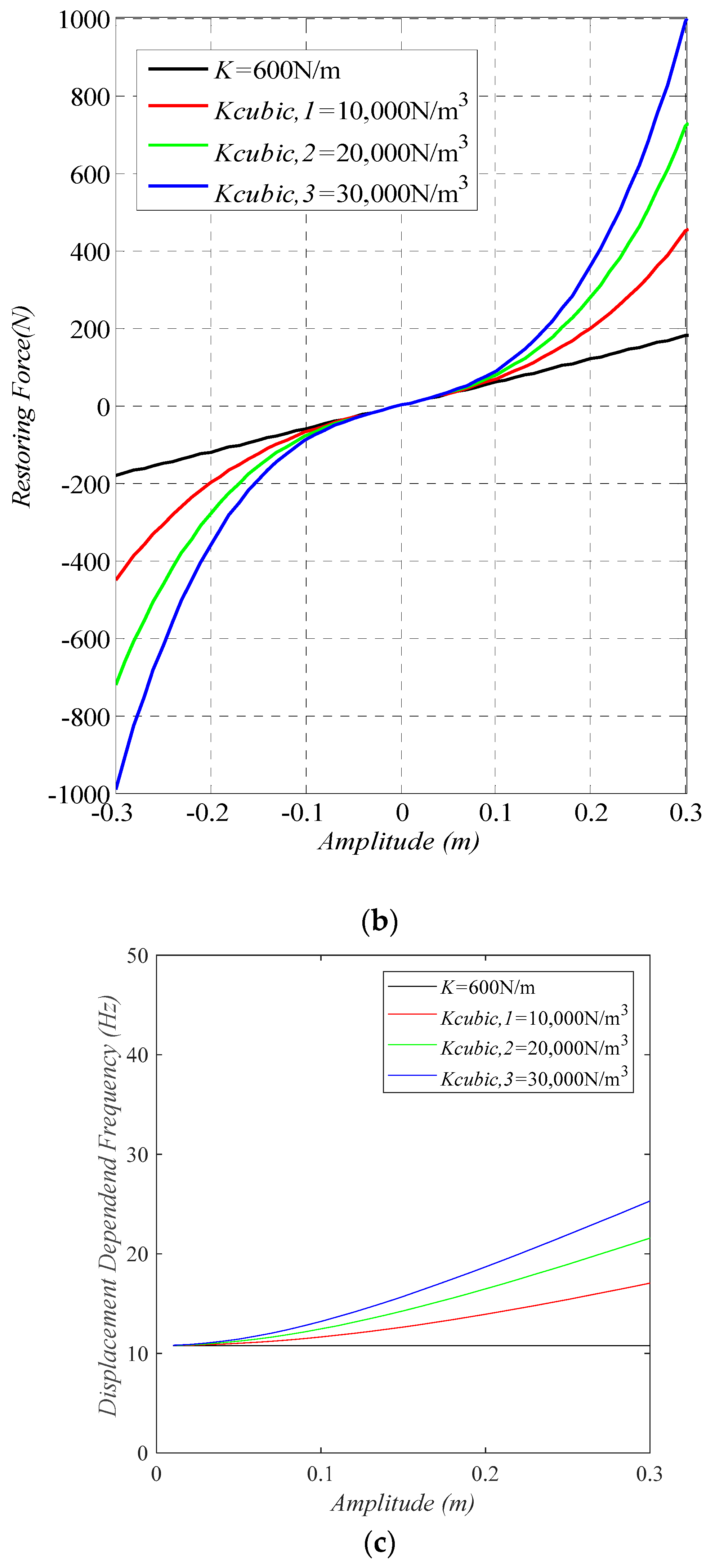
3. Nonlinear Cubic Stiffness Mathematical Model

The VIVACE converter can convert kinetic energy of flow to mechanical energy in the oscillator and, subsequently, to electrical energy through the generator [20]. In VIV, low onset velocity can be activated by a soft spring. The higher the spring stiffness, the higher the natural frequency, and the more power can be harnessed in the upper branch [21]. As the stiffness decreases, the oscillation amplitude increases resulting in higher energy harnessing [18]. On the other hand, lower K reduces the power in the oscillator proportionally. To overcome this problem a nonlinear spring stiffness can be implemented. The cubic stiffness function of such a spring is established as in Equation (1):
{ F n o n l i n e a r _ s p r i n g = K y + K c u b i c , n y 3 n = 1 ,    2 ,   3
where Kcubic,n is the parameter of the third-order term, which is proportional to the cubic spring displacement. In this paper, three different values of K are tested, 10,000, 20,000, and 30,000. The effect of cubic stiffness in restoring force and natural frequency are shown in Figure 4.
An important feature of the above-mentioned mathematical model of stiffness change is that its natural frequency of the system is variable. The natural frequency in vacuum ( f n = 1 2 π K m o s c ) changes with the amplitude, as shown in Figure 4b,c, respectively.
The linear part of the cubic function model is similar to that of a linear spring, which enables onset of FIO/V at low flow velocity for soft restoring force. On the other hand, the non-linear part of the formula can make the oscillator increase its natural frequency as the amplitude increases (Figure 4b,c), to expand the branches of VIV, play a transitional role between the VIV and galloping, and also enhance galloping [13]. Of course, galloping would occur only if turbulence stimulation is added to the smooth cylinder tested in this paper. The advantages of the above nonlinear system can potentially increase energy acquisition. The two most important advantages of the nonlinear cubic stiffness oscillator are summarized as follows:
(i) In terms of fluid velocity, compared with the previous studies of a locally rough cylinder [9] and smooth cylinder [7], increasing the natural frequency of the oscillator will delay the onset of VIV. In the cubic nonlinear stiffness model, the natural frequency of the system in water will increase with an increase of the amplitude, and the natural frequency will change faster when the amplitude exceeds a certain point, as shown in Figure 4c. Thus, the nonlinear model can expand the VIV branches along the range of availability of hydrokinetic energy in real flows making VIVACE a more effective CEC (see Section 5).
(ii) In the case of a cylinder with local roughness, there may be a gap region of low to zero response in the transition from VIV to galloping. The transition efficiency can be maximized by increasing the natural frequency of the oscillator and bridging the gap of the transition region. Although the utilization efficiency can be improved by adjusting the stiffness and additional damping [9], galloping is beyond the scope of the present study.
The results show that the linear stiffness oscillator cannot achieve the two advantages mentioned above. The nonlinear stiffness converter can achieve the above advantages [13].

4. The Mathematical Models of Harnessed Power and Efficiency in the Converter

Assuming the flow velocity, the motion of the cylinder and the central axis of the cylinder are located in the X, Y, and Z directions, respectively, the dynamic differential expression of the cylinder oscillation is:
m o s c y ¨ + c t o t a l y ˙ + K y + K c u b i c , n y 3 = F f l u i d
where mosc is the total oscillating mass including the transmission mechanism and equivalent spring mass, Ctotal is the total linear viscous damping, the spring stiffness is modeled per Equation (1), and Ffluid is the force produced by the fluid acting on the cylinder in the Y-direction. The real added mass—as opposed to the quiescent water added mass—is included on the right-hand side as part of the total hydrodynamic force.

4.1. Harnessed Power of Converter with Linear Spring Stiffness

In the system, additional harnessing damping is introduced to convert the kinetic energy of water flow in the model into mechanical energy, and finally into electrical energy through the converter. The total damping Ctotal is
c t o t a l = c s t r u c t u r e + c h a r n e s s
where cstructure is the existing damping due to losses in the transmission system, and charness is the damping added through Vck to convert mechanical energy in the cylinder oscillator to electrical energy. For a linear stiffness oscillator, in Equation (3), cstructure and charness can be expressed using the damping ratio ζstructure and ζharness, respectively, as
ζ s t r u c t u r e = c s t r u c t u r e 2 K m o s c
ζ h a r n e s s = c h a r n e s s 2 K m o s c
Then, the mechanical power in the VIVACE converter can be expressed as [6]
P c o n v e r t e d = 1 T o s c 0 T o s c 4 π m o s c ζ y ˙ 2 f n d t = 8 π 3 m o s c ζ t o t a l ( A f o s c ) 2 f n
When the excitation and response are sinusoidal (monochromatic), and the oscillation frequency is fosc, then, according to Equation (6), the energy lost (Pdissipated) and the energy harnessed (Pharness) are, respectively,
P d i s s i p a t e d = 8 π 3 m o s c ζ s t r u c t u r e ( A f o s c ) 2 f n
P h a r n e s s = 8 π 3 m o s c ζ h a r n e s s ( A f o s c ) 2 f n

4.2. Harnessed Power of the Nonlinear-Stiffness Restoring Force Oscillator

For linear systems, the converted power depends on measured amplitude and oscillation frequency. This relation would not apply to the nonlinear system of Equation (1). For the nonlinear system the dissipated and harnessed power are derived as follows:
P d i s s i p a t e d = 1 2 c s t r u c t u r e A 2 ω o s c 2
and
P h a r n e s s = 1 2 c h a r n e s s A 2 ω o s c 2
where A is the amplitude of the cylinder and ω o s c is the angular frequency of oscillation, which is measured through the encoder of the motor of the Vck system. Equations (9) and (10) do not rely on the added mass, so the value of the added mass does not need to be calculated in the process. The specific derivation process was pretested by [9]. In Foulhoux and Bernitsas (1993) [22], the reader can find the exact far-field approximation of the ideal-fluid inertia forces in a three-dimensional flow on a small body in a six-dimensional motion.

4.3. Harnessing Efficiency

The hydrokinetic power in a fluid flow through the surface (S) is:
P F l u i d = 1 2 ρ U 3 S
In the case of an oscillating cylinder, the area used is that swept by the cylinder. This yields
P F l u i d = 1 2 ρ U 3 ( 2 A max + D ) L
where Amax is the highest amplitude of the cylinder or all the cylinders in a multiple cylinder Converter. In the present tests, one cylinder is used, so only one Amax is defined. Unlike wind turbines or propellers, where the area is defined as the area swept by the blades in a fixed geometry, and FIO converter has a variable swept area per Equation (12). According to the Betz limit theorem [23], the maximum power that can be extracted from the open flow is 59.26%. Thus, the energy acquisition efficiency ηconverted and the harnessing efficiency ηharness of the system can be expressed as follows:
η c o n v e r t e d ( % ) = P c o n v e r t e d P F l u i d ( B e t z   L i m i t ) × 100
η h a r n e s s ( % ) = P h a r n e s s P F l u i d ( B e t z   L i m i t ) × 100
Typically, commercial-scale wind turbines achieve a peak efficiency of 75% to 80% of the Betz limit (Betz 1920).

5. Results and Discussion

The test parameters are listed in Table 2. The oscillatory response, including the amplitude ratio and the oscillation frequency (in the Appendix A) for each configuration, is presented in Section 5.1. The harnessed energy and harnessing efficiency are presented in Section 5.2.

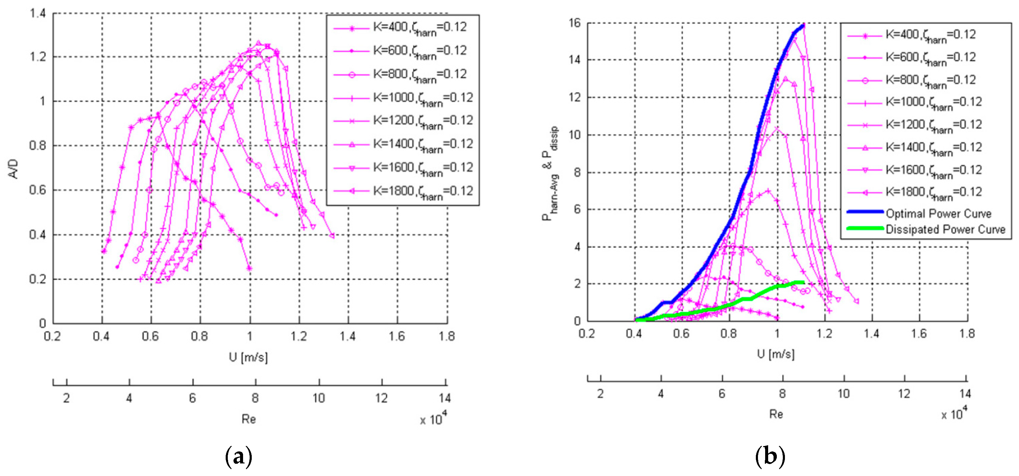
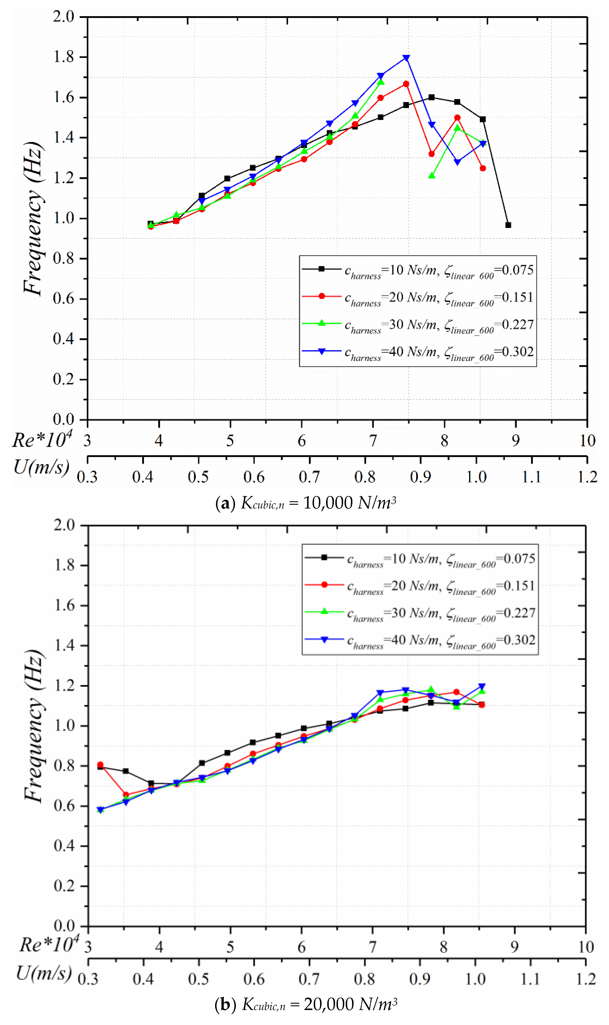
5.1. Amplitude Response

The amplitude ratio A/D measurements are presented in Figure 5. The amplitude of the cylinder is measured experimentally. It is calculated as the average of the highest 30 positive and 30 negative peaks occurring during the test after the transient. The deviation is represented by the error bars, as shown in the figures.
(1) In the initial VIV branch, at high cubic parameter Kcubic, the nonlinear cubic oscillator starts oscillating earlier than its linear counterpart in terms of flow speed. At lower nonlinear stiffness (Figure 5a), as the damping ratio increases, the oscillation decreases more than in the higher nonlinear parameters. This is also true for all VIV regions. As the flow speed increases, the drop in amplitude of the Kcubic = 10,000 N/m3 becomes substantial, while for higher damping charness = 40 Ns/m, the amplitude ratio drops by about 70%.
(2) The upper branch initiates at different Reynolds for different nonlinear cubic stiffness oscillators. As the cubic stiffness parameter increases, the VIV onset flow velocity increases. Specifically, for Kcubic,n = 10,000 N/m3, the initiation of the upper branch occurs at Re = 45,000. As Kcubic,n increases to 30,000 N/m3, the onset Re shifts to around 50,000.
(3) Compared to its linear counterpart, the most noticeable difference for the oscillation amplitude is that the range of the upper branch is much wider for the cubic stiffness oscillator. As the cubic parameter increases, the upper branch becomes wider. In the linear oscillator studies, (Lee et al. 2013) it has been already established that the upper branch shifts to higher flow speed as the spring-stiffness increases. The higher nonlinearity oscillator, at the same amplitude, has higher restoring force, thus resulting in a wider upper branch.
(4) In the lower branch, as the cubic factor increases, the initiation of the lower branch shifts to higher Reynolds. Specifically, for Kcubic,n = 10,000 N/m3, the onset of the lower branch is at Re = 69,000; at Kcubic,n = 30,000 N/m3, the initiation Re shifts to around 75,000. One noticeable difference compared to the linear counterpart for K = 600 N/m is that once the nonlinear oscillator reaches the lower branch, the amplitude drops more sharply than the linear oscillator. The range of the lower branch for all three nonlinear oscillators tested is shorter than the range of the linear oscillator. The reason for this effect is the following: In general, in the VIV lower branch, the oscillation amplitude becomes low, and the cylinder displacement is centered around the mean position of y = 0. According to Equation (1), the spring stiffness is low. For low spring-stiffness, the entire VIV range shifts to low flow-speeds. Thus, for low K the oscillator may already be past the range of VIV synchronization and the current lower branch of the nonlinear oscillator only catches the end of this region. As a consequence, in the amplitude ratio graphs for the nonlinear cubic oscillator, the transition from the upper branch to the lower branch and the desynchronization of VIV are abrupt.
Some remarks on the frequency response: In previous studies on the linear oscillator, the oscillation frequency, regardless of the damping, remains about the same. Here, however, due to the cubic nonlinear stiffness, it is obvious that as the amplitude increases, the equivalent natural frequency should increase accordingly. Thus, in Figure 6, in the lower to upper branch, the frequency increases due to the damping ratio decrease and, consequently, the induced higher amplitude.

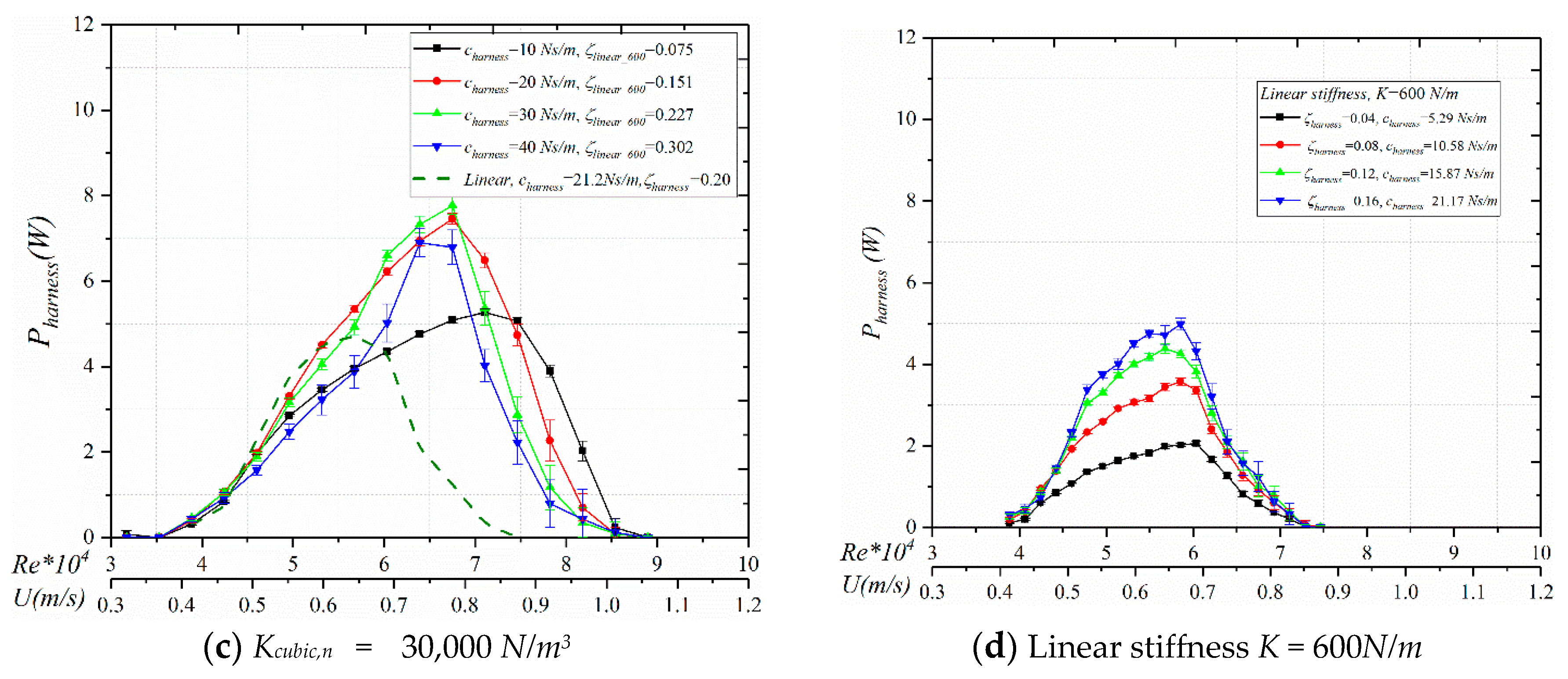
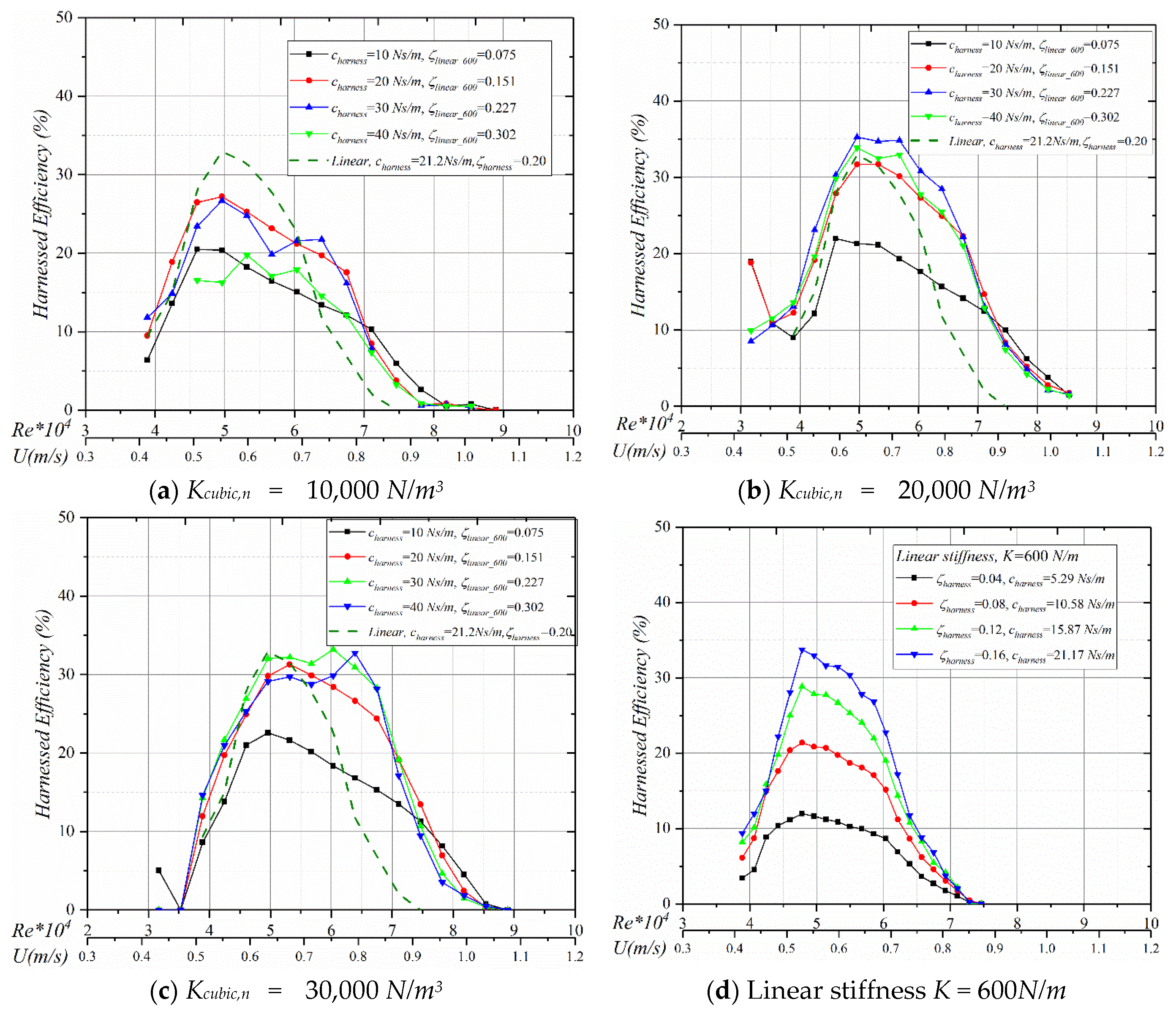
5.2. Harnessed Power and Harnessing Efficiency

The harnessed power and harnessing of the efficiency of the oscillator are presented in Figure 6 and Figure 7. Their values are calculated using the additional harnessed damping based on Equations (9)–(12).

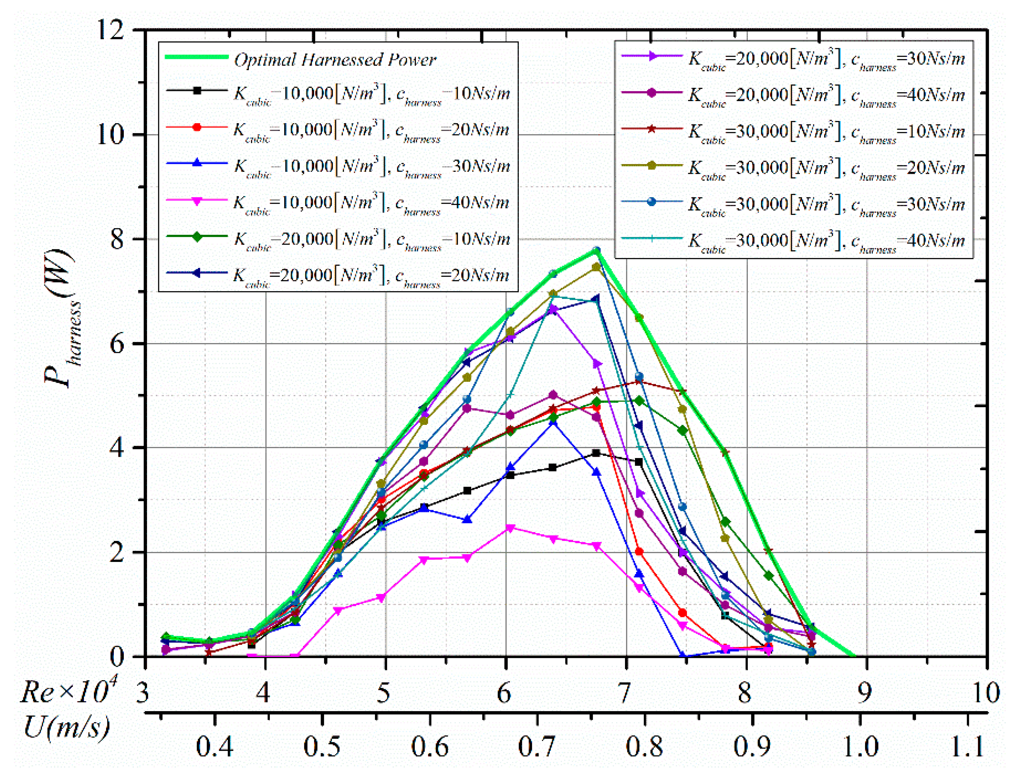
5.2.1. Harnessed Power

In all three nonlinear oscillators, for low harnessing damping (charness = 10 Ns/m), the harnessed power is consistently high in all the VIV regions, especially in the higher flow speeds, because of the hardening restoring force. Drops are less abrupt than for higher damping. This is contrary to the linear oscillator performance (Figure 6d), where the lower end of damping ratio values typically performs well only in the lower flow velocity. In other regions, the higher damping outperforms the lower damping more than twice.
(1) At the initial branch, both the nonlinear and linear stiffness converters have similar harnessed power trends. The energy harnessed by all the damping ratios is essentially the same, including the linear oscillator. Since the oscillation and the damping reach a balance, higher damping results in lower A/D, and vice versa. Consequently, the harnessed power does not vary much.
(2) Upper branch varies from 45,000 ~ 50,000 to 68,000 ~ 72,000. In all the cubic nonlinear oscillators, regardless of the cubic factor, the range of harnessed power becomes much wider than the linear oscillator. This trend is similar to the oscillatory amplitude response, especially in the upper branch. Compared to the linear stiffness K = 600 N/m oscillator, the range changed from 45,000 < Re < 60,000 to around 45,000 < Re < 68,000, thus, increasing about 50% at the higher upper branch. As the nonlinearity increases, the optimal harnessed power increases corresponding to different additional damping. Specifically, for the linear oscillator, the harnessed power increases as the damping increases. There exists a balance between the additional damping and power output [9], which is around 0.20 in the harnessed damping ratio. Higher damping would result in suppression of VIV. In the nonlinear cubic stiffness oscillator, for the lower cubic parameter (10,000 Ns/m3) and harnessing damping charness = 20 Ns/m, the harnessed power is stable and higher. As the cubic parameter increases, both charness = 20 and 30 Ns/m show higher and stable power output. The highest harnessed damping cases charness = 40 Ns/m, for all the nonlinear stiffness values, are not stable. Stability is quantified in the graphs by the error bars. Compared to the higher harnessed damping at the upper branch, the low damping charness = 10 Ns/m in all the cubic stiffness has stable harnessed power and does not show a sudden drop.
(3) Following the upper branch is the lower branch. Except for the low harnessed damping charness = 10 Ns/m, all power graphs have a sharper drop. The harnessed power line for the low damping case extends well beyond the upper branch to the lower branch. This is due to the fact that lower damping, in VIV, typically can extend the upper branch. In the lower branch, the harnessed power decreases as the damping increases, because in this region VV is not so strong and can be easily suppressed by higher damping. At low harnessed damping, the power increase, compared to 40 Ns/m is around 240% (Re = 74,000). This is different compared to the linear oscillator in Figure 6d, where the harnessed power decreases as the damping decreases.

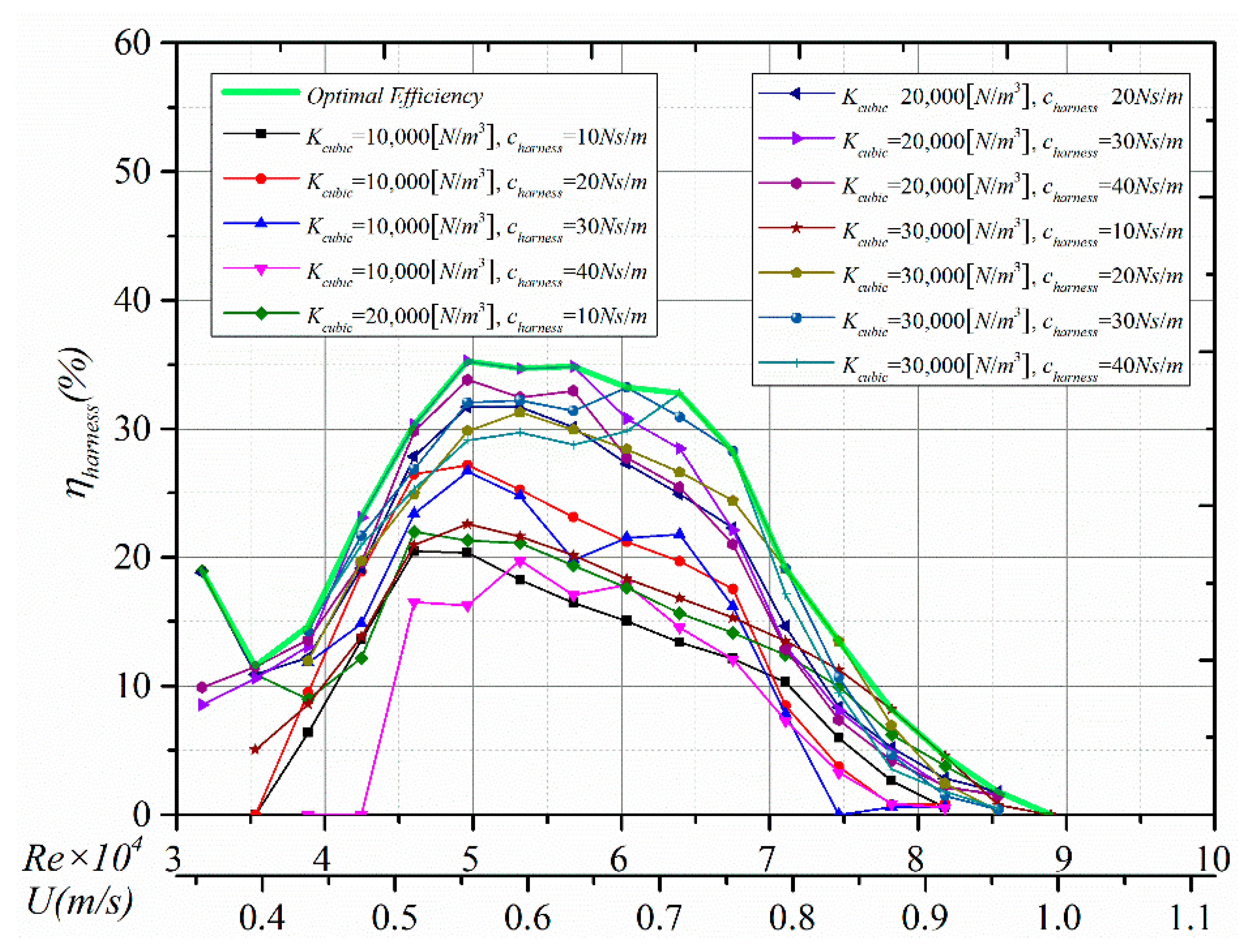
5.2.2. Harnessing Efficiency

(1) In the initial branch, the lower nonlinear oscillator with Kcubic = 10,000 Ns/m3 achieved the highest harnessing efficiency at charness = 20 Ns/m, because of its stable oscillation (Figure 4a). As the nonlinear cubic parameter increases, the nonlinear oscillator behaves the same exhibiting higher efficiency for higher harnessing damping. Overall, the harnessed power and harnessing efficiency are unstable in this region.
(2) Typically, in the VIV region, the highest harnessing efficiency occurs at the beginning of the upper branch [9] where power is locally high and amplitude has not reached its peak. Per Equation (11), at this point, the oscillator has a high numerator and low denominator. After the local optimum, the efficiency drops (Figure 7). For the nonlinear cubic stiffness, however, one noticeable difference in the efficiency in the upper branch is that all the efficiency graphs remain nearly straight lines with a slow drop. This becomes more obvious as the cubic parameter Kcubic increases. The lower cubic nonlinear stiffness behaves similarly to its linear counterpart. At the end of the upper branch, the harnessing efficiency of the nonlinear cubic oscillator is much higher than that of the linear counterpart, which is the result of the expanded oscillation range and the higher equivalent restoring force.
(3) In the lower branch, the harnessed efficiency of the linear stiffness oscillator follows the same trend as in the other VIV regions, the efficiency drops as the damping decreases. The difference, though, becomes less significant as the flow velocity increases. For instance, in Figure 7, at the beginning of the lower branch, Re = 65,000, the harnessing efficiency drops from 8.8% (ζharness = 0.20) to 3.6% (ζharness = 0.04). Near the end of the lower branch, the harnessing efficiency drops from 3.7% (ζharness = 0.20) to 1.7% (ζharness = 0.04). The harnessing efficiency is different from the linear oscillator. There are two transitions in the efficiency graph. At the beginning of the lower VIV branch, the efficiency continues from the upper branch, and the optimal value moves to the lower damping oscillator. Near the end of the VIV, the efficiencies of the three different nonlinear oscillators become nearly equal.

5.3. Design Considerations for the Cubic Stiffness Converter

The overall power envelopes of harnessed power and harnessing efficiency of the cubic stiffness Converter are presented in Figure 8. They are plotted from Figure 6 and Figure 7 to put the performance of the Converter into perspective.
In the power envelope (green line) of the tested cases, a steady increase in the harnessed power is shown, from the initial oscillation to the end of the upper branch. The peak is reached at the end of the upper branch, which is around Re = 67,500. After the peak, the harnessed power declines gradually as the flow velocity increases. The harnessing efficiency, on the other hand, reaches its peak around the beginning of the upper branch to around 35%. Then as the flow velocity increases, the efficiency decreases slightly in the upper branch to above 30%. Obviously, from the design perspective, the Converter is scalable. In the design phase of this Current Energy Converter (CEC), a balance of power and efficiency should be reached. Specifically, the power optimum and the efficiency optimum do not coincide because of the nature of Equation (11). This is beyond the scope of this research and the readers are referred to Bernitsas et al. 2016 [21].

6. Conclusions and Remarks

A current energy converter based on FIO and cubic nonlinear spring-stiffness were built, tested experimentally, and studied by changing systematically both the cubic parameter and additional harnessing damping. A cubic restoring-force spring basically is a type of hardening spring. It was proven to expend the VIV response to higher flow velocity. The oscillator is based on the Vck system developed in the MRELab of the University of Michigan with precise modeling, with minimal time-lag, and no force in the closed control loop to prevent bias of the measured response. The oscillatory response, harnessed power, and harnessing efficiency were measured and discussed. Comparisons with the corresponding linear-stiffness VIVACE converter were presented. The cubic nonlinear converter with a smooth cylinder achieves better performance than the linear oscillator. The main findings are:
(1) The cubic nonlinear stiffness oscillator has a much wider VIV range compared to its linear counterpart, regardless of the applied additional damping. The harnessed power range increases by 50% in the upper branch, which returns high and consistent harnessed power and efficiency over a broader range.
(2) The overall power increase compared to the linear oscillator is substantial. The peak power of the cubic nonlinear converter increases by 63%. The maximum power of the nonlinear converter occurs at the end of the upper branch.
(3) The efficiency of the cubic-stiffness converter in the upper branch remains nearly flat. This becomes more obvious as the cubic parameter Kcubic increases.
(4) The cubic-stiffness converter with low harnessing damping achieves consistently good performance in all the VIV regions because of the hardening restoring force, especially in the higher flow-velocity range. Contrary to the linear stiffness converter, the lower end of damping typically performs well only in the lower flow velocity.

Author Contributions

Software, G.J.; validation, M.L.; formal analysis, C.B.; data curation, G.J. and M.L.; writing—original draft preparation, C.B.; writing—review and editing, S.H. All authors have read and agreed to the published version of the manuscript.

Funding

This research was funded by the National Key Research and Development of China, grand number: YS2017YFGH000163, the Natural Science Foundation of Heilongjiang Province, grand number: YQ2019E017, and the Cooperative Agreement, grand number: DE-EE0006780 between Vortex Hydro Energy, Inc. and the U.S. Department of Energy. The MRELab of the University of Michigan is a subcontractor through Vortex Hydro Energy.

Conflicts of Interest

The authors declare no conflict of interest.

Nomenclature

AAmplitude of transverse displacement
CharnessHarnessing damping
CstructureFrictional damping
ctotalTotal damping
DDiameter of cylinder
fnNatural frequency in vacuum
fn,waterNatural frequency in inviscid water
foscOscillation frequency of cylinder
fFrequency (Hz)
FfluidForce exerted by the fluid on the cylinder in the y-direction
kAverage grit height
KSpring stiffness
Kcubic,nCubic spring stiffness
LCylinder length
moscOscillating mass
maAdded mass
mdMass of fluid displaced by oscillating cylinder
m*Mass ratio
PdissipatedDissipated power
PfluidPower in fluid flow
PharnessHarnessed power
ReReynolds number
SSurface through which fluid flows
UFlow velocity
U*Reduced velocity
y Instantaneous cylinder motion in transvers direction
y ˙ Instantaneous cylinder velocity in transvers direction
y ¨ Instantaneous cylinder acceleration in transvers direction
Greek Letters
ζharnessHarnessing damping ratio
ζstructureFrictional damping ratio
ζtotalTotal damping ratio
η c o n v e r t e d Efficiency in power conversion
η h a r n e s s Efficiency in power harnessing
ω o s c Angular frequency of oscillation

Appendix A

Figure A1 shows the response frequency for the three different cubic stiffness values tested with four different damping values. Due to the hardening spring as the amplitude increases, the frequency increases. In addition, in the upper branch, higher damping results in higher response frequency.
Figure A1. Frequency response (Hz) of three cubic nonlinear oscillators with Kcubic,n [N/m3] = (a) 10,000, (b) 20,000, (c) 30,000.
Energies 13 03283 g0a1aEnergies 13 03283 g0a1b

References

  1. Bernitsas, M.M.; Ofuegbe, J.; Chen, J.U.; Sun, H. Eigen-Solution for Flow Induced Oscillations (VIV and Galloping) Revealed at the Fluid-Structure Interface. In Proceedings of the ASME 2019 38th International Conference on Ocean, Offshore and Arctic Engineering, Glasgow, UK, 9–14 June 2019. [Google Scholar]
  2. Sarpkaya, T. A critical review of the intrinsic nature of vortex-induced vibrations. J. Fluids Struct. 2004, 19, 389–447. [Google Scholar] [CrossRef]
  3. Bearman, P.W. Circular cylinder wakes and vortex-induced vibrations. J. Fluids Struct. 2011, 27, 648–658. [Google Scholar] [CrossRef]
  4. Mackowski, A.W.; Williamson, C.H. Developing a cyber-physical fluid dynamics facility for fluid–structure interaction studies. J. Fluids Struct. 2011, 27, 748–757. [Google Scholar] [CrossRef]
  5. Williamson, C.H.K.; Govardhan, R. Vortex-induced vibrations. Annu. Rev. Fluid Mech. 2004, 36, 413–455. [Google Scholar] [CrossRef] [Green Version]
  6. Vikestad, K.; Vandiver, J.K.; Larsen, C.M. Added mass and oscillation frequency for a circular cylinder subjected to vortex-induced vibrations and external disturbance. J. Fluids Struct. 2000, 14, 1071–1088. [Google Scholar] [CrossRef]
  7. Lee, J.H.; Xiros, N.; Bernitsas, M.M. Virtual damper–spring system for VIV experiments and hydrokinetic energy conversion. Ocean Eng. 2011, 38, 732–747. [Google Scholar] [CrossRef]
  8. Bernitsas, M.M.; Raghavan, K.; Ben-Simon, Y.; Garcia, E.M.H. VIVACE (Vortex Induced Vibration Aquatic Clean Energy): A new concept in generation of clean and renewable energy from fluid flow. J. Offshore Mech. Arct. Eng. Trans. ASME 2008, 130, 041101. [Google Scholar] [CrossRef]
  9. Sun, H.; Kim, E.S.; Nowakowski, G.; Mauer, E.; Bernitsas, M.M. Effect of mass-ratio, damping, and stiffness on optimal hydrokinetic energy conversion of a single, rough cylinder in flow induced motions. Renew. Energy 2016, 99, 936–959. [Google Scholar] [CrossRef] [Green Version]
  10. Ma, C.; Sun, H.; Nowakowski, G.; Mauer, E.; Bernitsas, M.M. Nonlinear piecewise restoring force in hydrokinetic power conversion using flow induced motions of single cylinder. Ocean Eng. 2016, 128, 1–12. [Google Scholar] [CrossRef] [Green Version]
  11. Barton, D.A.; Burrow, S.G.; Clare, L.R. Energy harvesting from vibrations with a nonlinear oscillator. J. Vib. Acoust. 2010, 132, 021009. [Google Scholar] [CrossRef]
  12. Ma, C.; Sun, H.; Bernitsas, M.M. Nonlinear Piecewise Restoring Force in Hydrokinetic Power Conversion Using Flow-Induced Vibrations of Two Tandem Cylinders. J. Offshore Mech. Arct. Eng. 2018, 140. [Google Scholar] [CrossRef]
  13. Sun, H.; Bernitsas, M.M. Bio-Inspired adaptive damping in hydrokinetic energy harnessing using flow-induced oscillations. Energy 2019, 176, 940–960. [Google Scholar] [CrossRef] [Green Version]
  14. Cottone, F.; Vocca, H.; Gammaitoni, L. Nonlinear energy harvesting. Phys. Rev. Lett. 2009, 102, 080601. [Google Scholar] [CrossRef] [PubMed] [Green Version]
  15. Ferrari, M.; Ferrari, V.; Guizzetti, M.; Andò, B.; Baglio, S.; Trigona, C. Improved energy harvesting from wideband vibrations by nonlinear piezoelectric converters. Sens. Actuators A Phys. 2010, 162, 425–431. [Google Scholar] [CrossRef] [Green Version]
  16. Abdelkefi, A.; Hajj, M.R.; Nayfeh, A.H. Phenomena and modeling of piezoelectric energy harvesting from freely oscillating cylinders. Nonlinear Dyn. 2012, 70, 1377–1388. [Google Scholar] [CrossRef]
  17. Huynh, B.H.; Tjahjowidodo, T.; Zhong, Z.W.; Wang, Y.; Srikanth, N. Numerical and experimental investigation of nonlinear vortex induced vibration energy converters. J. Mech. Sci. Technol. 2017, 31, 3715–3726. [Google Scholar] [CrossRef]
  18. Sun, H.; Kim, E.S.; Bernitsas, P.M.; Bernitsas, M.M. Virtual Spring–Damping System for Flow-Induced Motion Experiments. J. Offshore Mech. Arct. Eng. 2015, 137, 061801. [Google Scholar] [CrossRef]
  19. Kinaci, O.K.; Lakka, S.; Sun, H.; Bernitsas, M.M. Effect Of Tip-Flow On Vortex Induced Vibration Of Circular Cylinders For R e   <   1.2   ·   10 5 . Ocean Eng. 2016, 117, 130–142. [Google Scholar] [CrossRef] [Green Version]
  20. Lee, J.H.; Bernitsas, M.M. High-damping, High-Reynolds VIV tests for energy harnessing using the VIVACE converter. Ocean Eng. 2011, 38, 1697–1712. [Google Scholar] [CrossRef]
  21. Bernitsas, M.M. Harvesting Energy by Flow Included Motions; Chapter 47; Springer Handbook of Ocean Engineering; Springer: Berlin/Heidelberg, Germany, 2016. [Google Scholar]
  22. Foulhoux, L.; Bernitsas, M.M. Forces and Moments on a Small Body Moving in a 3-D Unsteady Flow. J. Offshore Mech. Arct. Eng. ASME Trans. 1993, 115, 91–104. [Google Scholar] [CrossRef]
  23. Betz, A. Das Maximum der theoretisch möglichen Ausnützung des Windes durch Windmotoren. Z. Gesamte Turbinenwesen 1920, 26, 307–309. [Google Scholar]
Figure 1. (a) Amplitude response and (b) harnessed and dissipated power of a smooth cylinder, at various linear spring-stiffness values K (Lee and Bernitsas 2011).
Energies 13 03283 g001
Figure 2. Schematic of the LTFSW channel with a VIVACE converter model.
Energies 13 03283 g002
Figure 3. A VIVACE Converter model with the Vck controller mounted: (a) VIVACE converter 3D model. (b) The servomotor with the Vck (Virtual spring-damping system) shaft. (c) The single-cylinder converter in the LTFSW channel (top view). (d) Cylinder model with the adjustable mass axis.
Energies 13 03283 g003aEnergies 13 03283 g003b
Figure 4. Cubic stiffness parameter Kcubic,n: (a) Schematic of the oscillator. (b) The curves of restoring force vs. amplitude. (c) The curves of natural frequency in vacuum water vs. amplitude.
Energies 13 03283 g004aEnergies 13 03283 g004b
Figure 5. Amplitude ratio of three cubic nonlinear oscillators: Kcubic,n [N/m3] = (a) 10,000; (b) 20,000; (c) 30,000; (d) Linear oscillator: stiffness K = 600N/m with ζharness = 0.04~0.12.
Energies 13 03283 g005
Figure 6. Harnessed power [W] of three cubic nonlinear oscillators: Kcubic,n [N/m3] = (a) 10,000; (b) 20,000; (c) 30,000; (d) Linear oscillator: stiffness K = 600N/m with ζharness = 0.04~0.12.
Energies 13 03283 g006aEnergies 13 03283 g006b
Figure 7. Harnessing efficiency (%) of three cubic nonlinear oscillators: Kcubic,n [N/m3] = (a) 10,000; (b) 20,000; (c) 30,000; (d) Linear oscillator: stiffness K = 600N/m with ζharness = 0.04~0.12.
Energies 13 03283 g007
Figure 8. The power and efficiency envelopes of the cubic spring-stiffness oscillators.
Energies 13 03283 g008aEnergies 13 03283 g008b
Table 1. Specifications of the experimental apparatus (model Converter, m* is the mass ratio).
Mass RatioAspect RatioMaximum Oscillatory AmplitudeLongitudinal Distance
0.91 ≤ m* ≤ 1.98L/D = 10.29Amax/D3.5” = 5.01.429 ≤ d/D3.5” ≤ 6.0
Table 2. Particulars of the cubic nonlinear stiffness oscillator with a single smooth cylinder.
Test Parameters
K [N/m] (Based stiffness)600
fn [Hz] (K = 600 N/m)1.44
fn,water [Hz] (K = 600 N/m) 1.09 (quiescent water)
Kcubic,n [N/m3]10,000; 20,000; 30,000
charness [Ns/m]10, 20, 30, 40
cstructure [Ns/m]3.41
D [m]0.0889
L [m]0.895
md = ρπD2/4 [kg]5.425
mosc [kg]7.286
ma [kg] (inviscid)5.425
Temperature [°C]18.5~20.5
μ [N s/m2]1.004 × 103
υ [m2/s]9.940 × 107
ρ [kg/m3]999.729

