Article

Performance Improvement of Matrix Converter Direct Torque Control System

1
College of Automation and Electronic Information, Xiangtan University, Xiangtan 411105, China
2
Department of Electrical Engineering, Tsinghua University, Beijing 100083, China
3
College of Electrical Engineering, Naval Engineering University, Wuhan 430033, China
4
College of Public Administration, Xiangtan University, Xiangtan 411105, China
*
Authors to whom correspondence should be addressed.
Energies 2020, 13(12), 3247; https://doi.org/10.3390/en13123247
Submission received: 27 May 2020 / Revised: 14 June 2020 / Accepted: 19 June 2020 / Published: 23 June 2020
(This article belongs to the Special Issue RES-Based Generators and Electric Storage Systems)

Abstract

:
In asynchronous motor direct torque control systems, the power supply using the matrix converter can achieve the effect of direct torque control and also has the advantages of the matrix converter. Nonetheless, direct torque control still has drawbacks in terms of pulsation. In this paper, the characteristics of direct torque control method and its existing problems are analyzed in depth. In view of the shortcomings of torque ripple, an improved scheme of torque tracking control is proposed based on conventional control methods. On the basis of theoretical simulation, DSP and FPGA algorithms are designed respectively in C language and VHDL to implement the proposed control strategy. Finally, a highly integrated experimental platform of matrix converter has been developed to verify the proposed control strategy. The simulation and experimental results verify the correctness and effectiveness of the improved scheme.

1. Introduction

In existing AC speed regulation systems, AC-DC-AC type converter and AC-AC type converter account for a large proportion. The AC-DC-AC converter is widely used in practical work, but with the improvement of energy saving and emission reductions and greater safety performance requirements, it still has many shortcomings: (1) Owing to the structural limitations of AC-DC-AC converters, the DC energy storage link takes up a lot of space, which leads to heavy equipment that is not easy to maintain. (2) When the motor is in the braking state, due to the presence of the braking resistor, a large amount of heat that cannot be recycled will be generated, resulting in the problem of low energy efficiency. On the other hand, this heat will generate high temperatures, which pose a greater threat to inflammable and explosive working environments and compromise safety [1,2,3].
Traditional AC-AC converters can realize the frequency change of current and voltage without too many converter times, but the large number of thyristors used in this converter structure results in the low power factor of the system. As microelectronics technology and power electronics technology continue to develop, various power conversion devices have been launched. The direct matrix converter (DMC) is a unidirectional forced AC/AC conversion system with sinusoidal input current and output voltage and a controllable input power factor, but without any energy storage elements [4]. Due to the lack of energy storage components, compared with traditional AC-DC converters, DMC has higher reliability and a smaller form factor [5,6]. As locomotive traction systems and distributed energy systems are rapidly developed in industry, it is essential to conduct further research on power converters with high performances.
After direct torque control (DTC) technology was first proposed by German experts on IEEE in the 1980s, it developed into a leading technology for AC speed regulation at an astounding pace [7,8,9]. It omits complicated vector transformation and simplified processing of motor mathematical model, simple control structure, direct control means, and clear physical concept of signal processing, making the problem particularly simple and clear. The torque response of this control system is fast, and it is an AC speed regulation method with high dynamic and static performance [10,11]. There are still some problems with this method: it requires accurate and effective observation of the stator flux linkage, the flux torque ripple is large, and the inverter switching frequency is not fixed. When the motor runs at low speed, the stator resistance voltage will drop, and the control performance is easily disturbed by external uncertainties [12,13].
It proposed a direct torque control strategy based on a four-dimensional switch table, which increases the number of selectable voltage vectors, but also increases the complexity of control [14]. In [15], SVPWM was introduced into the DTC algorithm. This method obtains motor variable error through the PI controller, and then calculates and obtains the space voltage vector, and then synthesizes the voltage vector through SVPWM and outputs it. As a result of the inherent properties of the PI regulator in practice, the SVPWM-DTC algorithm cannot cope with changes in the inherent parameters of the motor operation process, torque pulsation and load disturbances still exist. Reference [16] adopted a double closed-loop torque and flux linkage DTC strategy based on space vector pulse width modulation, which can effectively reduce torque ripple and has good dynamic and steady-state performance. However, as this strategy uses space vector pulse width modulation, the amount of calculation is large. It used sliding mode control for torque control, and obtained the DTC algorithm based on SMC, which reduced the flux linkage and torque ripple amplitude. Generally, the sliding mode speed controller is generally used in vector control, and when the sliding mode structure is used in direct torque control, it is generally used for torque and flux control, so it is relatively complicated [17].
In this paper, a direct torque control strategy for high performance speed control system of induction motor powered by matrix converter is implemented. The asynchronous motor powered by the direct matrix converter adopts the direct torque control method, which can exert the advantages of both, such as: (1) high output power factor, about equal to 1; (2) rapid torque response of the system; (3) good input current waveform and less harmonic content [8,9].With this control strategy, the space vector modulation algorithm of matrix converter and the direct torque control of induction motor based on stator field orientation can be realized simultaneously [18]. The dynamic and static performances of torque and flux linkage in asynchronous motor direct torque control systems are analyzed in depth. Aiming at the defects of torque ripple, an improved scheme of torque tracking control is proposed based on the conventional control method. The direct torque control experiment was completed on the MATLAB/Simulink platform. The results of simulation and experiment show that the improved AC speed control system can reduce the torque ripple and improve the performance of the whole system. DTC not only has good robustness, but also has fast and precise control effects.

2. Basic Principle and Modulation Strategy of Direct Matrix Converter

2.1. Status of Direct Matrix Converter

As a new type of AC-AC inverter, DMC has many advantages: it realizes the bidirectional flow of electrical energy, the input current and output voltage are sine waves, the input side power factor can be adjusted arbitrarily, no intermediate DC energy storage link, small size, compact structure, and low harmonic pollution. Hence, DMC has become a research hotspot of AC-AC frequency conversion and has been valued by researchers at home and abroad in the field of motor drive.

2.2. Basic Principle of Direct Matrix Converter

The most general topology of a direct matrix converter is shown in Figure 1. It is a 3 × 3 matrix array composed of nine bidirectional switches, and each bidirectional switch is composed of IGBTs and diodes [6].

2.3. Modulation Strategy of Direct Matrix Converter

In order for the direct matrix converter to work properly, two important principles need to be followed:
(1)
No short circuit between any two phases of the three-phase input terminals a, b, and c of the matrix converter.
(2)
The three-phase output terminals A, B, and C of the matrix converter cannot be disconnected between any single phases.
Based on the above two important principles, this paper defines
S i j ( t ) = { 1 S i j t u r n   o n 0 S i j t u r n   o f f    i = A , B , C ; J = a , b , c
It can get
S i a + S i b + S i c = 1
This paper defines the control vectors of input and output phase voltages as
U i = 2 3 ( u a + u b e j 2 π / 3 + u c e j 4 π / 3 ) i = U i m e j α i
U o = 2 3 ( u A + u B e j 2 π / 3 + u C e j 4 π / 3 ) i = U o m e j α o
where ua, ub, uc, uA, uB, and uC are three-phase input and output terminal voltage vectors respectively; Uim and Uom are input and output phase voltage control vector amplitudes; αi and αo are the phases of their vectors respectively.
Similarly, this paper defines the space vector of input and output current as
I i = 2 3 ( i a + i b e j 2 π / 3 + i c e j 4 π / 3 ) i = I i m e j β i
I o = 2 3 ( i A + i B e j 2 π / 3 + i C e j 4 π / 3 ) i = I o m e j β o
where ia, ib, ic, iA, iB, and iC are the three-phase input and output current vectors; Iim and Iom are the magnitudes of the input and output phase current control vectors; βi and βo are the phases of their vectors.
Combining the defined space vector and safe switching principles, the matrix converter has 27 working states in the actual working process which can be divided into three groups. The first group is called ‘invalid structure’, and the output phase voltage and phase current have no fixed direction. The second group is called ‘effective structure’, and the direction of the space vector of the output phase voltage and input phase current is fixed as shown in Figure 2. The third group is a ‘zero vector’ combination of three switches, which produces zero output voltage vector and zero input current vector.

3. Principle of Direct Torque Control Strategy of Asynchronous Motor Based on Direct Matrix Converter

3.1. The Basic Concept of Direct Torque Control for Asynchronous Motors

To achieve the control of the motor speed, the key is to control the motor torque. Direct torque control is to control the motor torque by changing the flux angle. Direct matrix converter-direct torque control system consists of voltage space vector table, direct matrix converter, torque regulator, sector judgment module, motor, etc. The direct torque control of the asynchronous motor is mainly achieved by selecting different voltage space vectors. The selection of this vector is obtained by synthesizing the flux control signal, the sector number where the flux is located, and the torque control signal.

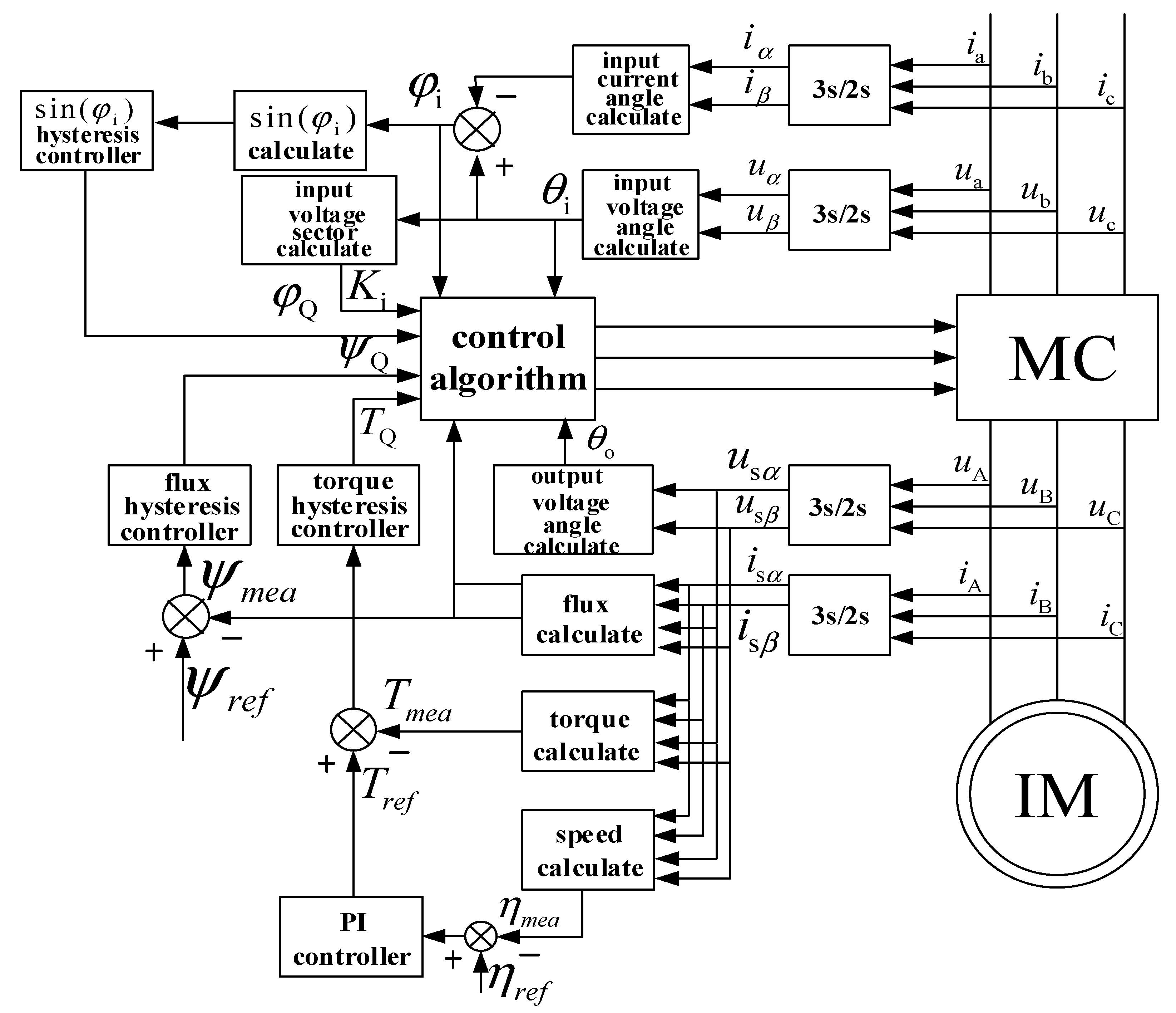
3.2. The Principle of Direct Matrix Converter-Direct Torque Control System of Asynchronous Motors

In the DTC control strategy, the key is to control stator flux and electromagnetic torque. The block diagram of DMC-DTC control system is shown in Figure 3. Specifically, by detecting the three-phase output voltage and current of direct matrix converter, the amplitude, vector angle, and two-point hysteresis output of flux are calculated by vector transformation; the reference value of electromagnetic torque is obtained by PI adjustment of the speed of asynchronous motor, and the hysteresis output of torque is obtained by comparison with the actual torque. Through the control logic, the feedback value of electromagnetic torque and the amplitude of stator flux follow the given value in real time to achieve the purpose of direct control of torque and flux. It can be seen that the advantage of this control is the direct control of torque. It is not necessary to simplify the mathematical model of the AC motor for decoupling, which greatly mitigates the problem that the control performance in vector control technology is susceptible to changes in load parameters. Hence, it largely overcomes the shortcomings of vector control.
The observation equation of stator flux and torque of asynchronous motor is
{ ψ s α = ( u s α i s α R s ) d t ψ s β = ( u s β i s β R s ) d t
θ s = arctan ψ s α ψ s β
T e = 3 2 n p ( ψ s α i s β ψ s β i s α ) = 3 2 n p | ψ s i s |
where u and u are the components of the stator voltage on the αβ axis; i and i are the components of the stator current on the αβ axis.
Equation (7) is obtained from the stator voltage and current components by detecting the voltage and current on the output side of the matrix converter and converted by 3/2. Equation (8) is the sector angle where the magnetic flux is located, and np is the pole pair number of the asynchronous motor.
The flux regulator output is 1 and −1, the specific logic is
C ψ = { 1                   E ψ H ψ 1             E ψ < H ψ ,
where E ψ is the differential output of the magnetic flux, E ψ = ψ f ψ g ; H ψ is the tolerance of the magnetic flux; 1 indicates that the magnetic flux needs to be reduced, and −1 indicates that the magnetic flux needs to be increased.
The torque regulator outputs 1, 0 and −1, the specific logic is
C T = { 1                   E T H T 0                   H T < E T < H T 1             E T H T
where E T is the torque differential output, E T = T f T g ; H T is the torque tolerance; 1 means the torque needs to be reduced, −1 means the torque needs to be increased, and 0 means the torque remains unchanged.
Based on the above analysis, the relationship between the sectors where the magnetic flux is located, the torque, and the hysteresis output of the magnetic flux are shown in Table 1, therefore the voltage space vector of the corresponding output can be obtained by looking up the table.
Hysteresis comparison is performed between the actual calculated torque and flux linkage of the motor during operation with the given reference torque and reference flux linkage value, and the output logic value is obtained by looking up the table to obtain the required output voltage vector. Considering the input power factor control, the power factor two-point hysteresis comparator is introduced to directly control the variable sin φ i , and the output variable sin φ i - Q is 1 and −1. The specific logic is
sin φ i - Q = { 1 sin φ i - f > sin φ i - g + ε φ i 1 sin φ i - f sin φ i - g ε φ i
where sin φ i - Q is hysteresis output; sin φ i - f is the calculated value of input power; sin φ i - g is the given value of power factor; ε φ i is the tolerance of angle sine; 1 means the power factor needs to be reduced, and −1 means the power factor remains unchanged.
According to the output voltage space vector and the hysteresis output of the input power factor, combined with the sector number where the input space voltage vector is located, the switch state table of the entire system is obtained, as shown in Table 2.
The required output voltage vector is obtained by querying Table 1, and combined with Table 2 to obtain the required switching state, so as to directly and quickly reach the goal of controlling the magnetic flux and torque; therefore, the stator flux and electromagnetic torque can achieve the desired results. As a result, the magnetic flux waveform is circular, and the torque response is fast and follows the reference value [8].

4. Performance Improvement of Direct Torque Control System

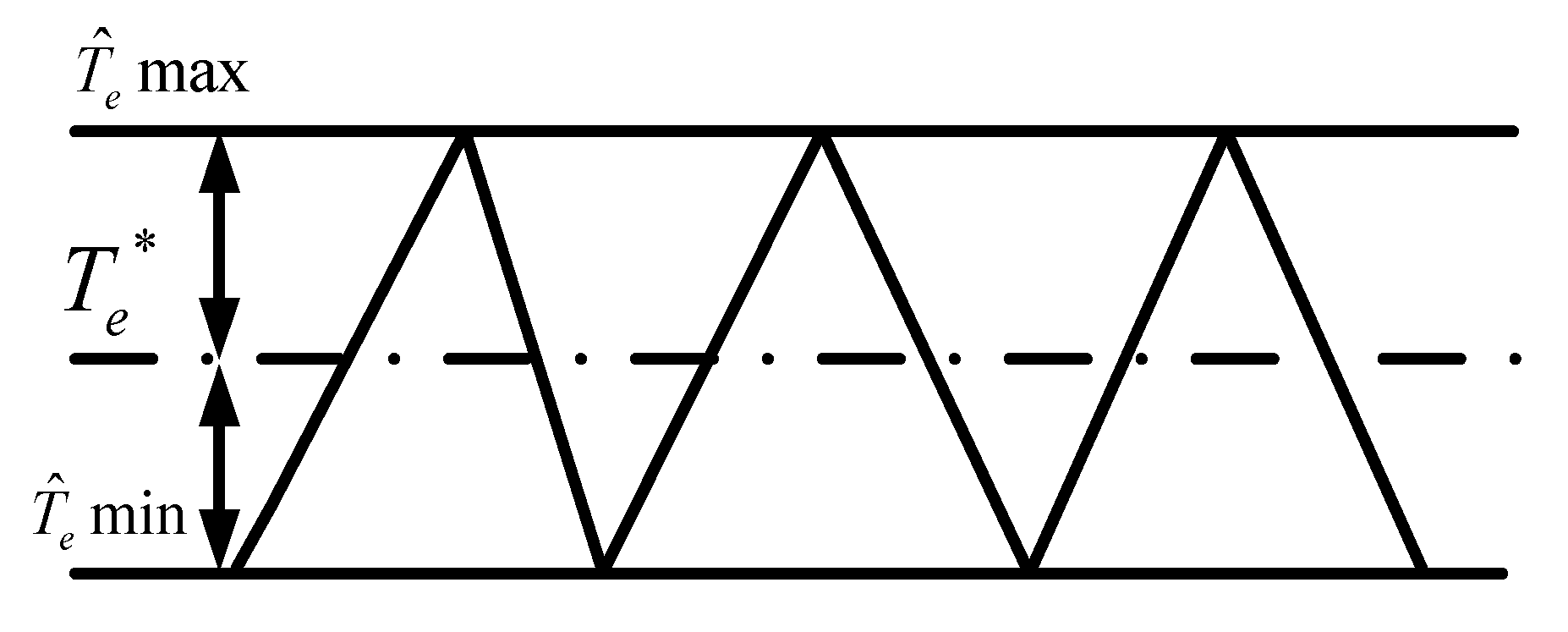
4.1. Torque Ripple Analysis

In digital control systems, the sampling period is generally fixed. In the basic direct torque control strategy, generally only one voltage vector is output during a sampling period. In this way, the magnitude of the error between the motor output torque and the command value is determined by Equation (13).
L σ d d t T e = n p ( ψ r × U s ) n p ω r ψ s · ψ r R m T e   Δ T e = T ^ e T e * T s L σ [ n p ( ψ r × U s ) n p ω r ψ s · ψ r R m T e ]
Figure 4 shows a schematic diagram of torque fluctuations. The following analyzes how the torque varies with the rotation speed ωr and torque when the sampling period is constant.
From Equation (13)
T ^ e   max T e * T s L σ [ n p ( ψ r × U s ) n p ω r ψ s · ψ r R m T ^ e ]
T ^ e   min T e * T s L σ [ n p ω r ψ s · ψ r R m T ^ e ]
Subtract (14) from (15) to get
Δ T ^ e = T ^ e   max T ^ e   min T s L σ n p ( ψ r × U s ) n p · T s L σ ( ψ s × U s )
It can be seen from (16) that the upper limit and lower limit of torque fluctuation are different, and the magnitude of load and speed are independent.
From (14) and (15) we can know:
  • When the motor is running at high speed or medium speed and heavy load, the torque rise may be less than the torque drop during one sampling period. The actual average torque has a negative offset from the command value.
  • When the motor is running at medium lower speeds and heavy load, the rise of torque may be approximately equal to the drop of torque during a sampling period. The actual average torque is basically equal to the command value without bias.
  • When the motor is running in the low speed range, especially when the very low speed is close to zero speed, the torque rise may be greater than the torque drop in a sampling period. The actual average torque has a positive offset from the command value.
The above three conditions result in three different torque ripple waveforms as shown in Figure 5.
In Figure 6, the above three cases are simulated respectively. Specific simulation parameters are shown in Table 3. It can be seen that the simulation results are basically consistent with the analysis, and it can be seen that the amplitudes of torque pulse are roughly the same in the three cases.
Another phenomenon is also noteworthy, namely the zigzag pulsation of torque. It is clearly shown in Figure 6a,c. One is the saw tooth of periodic uplink and the other is the saw tooth of periodic downlink, both of which are caused by the different rate of torque change when the torque increases or decreases in a sampling period.

4.2. Torque Tracking Algorithm

In the period of action of a non-zero working vector, this method shortens the action time of non-zero vector at a proper time, and inserts zero vector in the remaining time, therefore the torque error in this beat tends to zero as much as possible, so as to achieve the purpose of reducing torque ripple.
It is assumed that according to the current torque and flux regulator output, the non-zero vector V K to be applied for the next beat has been selected as its acting time T K , and the zero vectors will be applied for the remaining time T S T K .
At this time, the torque error is: Δ T ^ e = T e * T ^ e > 0 .
Then, in the time of 0 T K the torque rise change is
Δ T ^ e = 1 L σ [ n p ( ψ r × V K ) n p ω r ψ s · ψ r R m T ^ e ] · T K
Similarly, in the time of T K T S , the decrease of torque is
Δ T ^ e = 1 L σ [ n p ω r ψ s · ψ r R m T ^ e ] · ( T S T K )
To make the torque error tend to zero in one beat, there is
Δ T ^ e = Δ T ^ e + Δ T ^ e
Replace (17) and (18) into (19) and we can get
T K = L σ Δ T ^ e + ( R m T ^ e + n p ω r ψ s · ψ r ) T S n p ( ψ r × V K )
Considering ψ s = ψ r , (20) can be simplified as
T K L σ Δ T ^ e + ( R m T ^ e + n p ω r | ψ s | 2 ) T S n p ( ψ s × V K )
For the time value calculated by Formula (21), the following two points are discussed:
  • T K T S , indicating that the difference between the torque and the command value is large at this time, and the non-zero vector effect cannot reach the command value, therefore it is not necessary to apply a zero vector, and T K = T S can be used.
  • T K < T S , which means that the torque can reach the command value in one cycle at this time, therefore the zero vectors need to be added.
Through the above analysis, it is not difficult to find that the torque tracking algorithm plays a different role in the three torque ripple cases analyzed above, as this method only controls the amount of change in torque rise, and when the torque needs to fall, the applied is already a zero vector. The analysis is as follows:
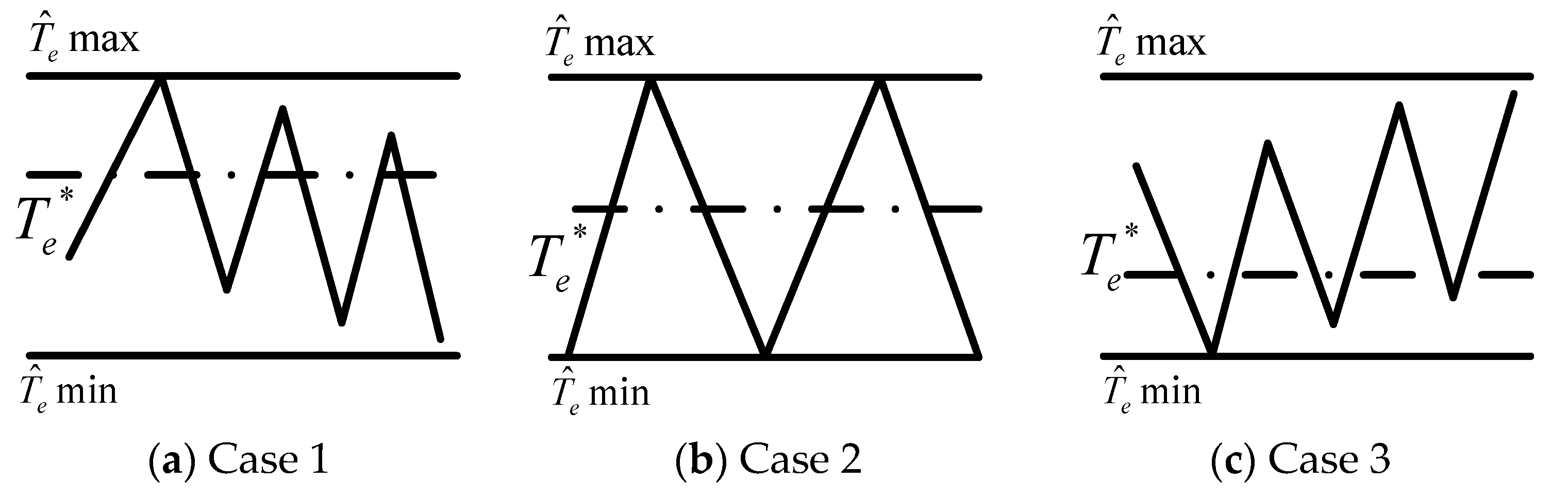
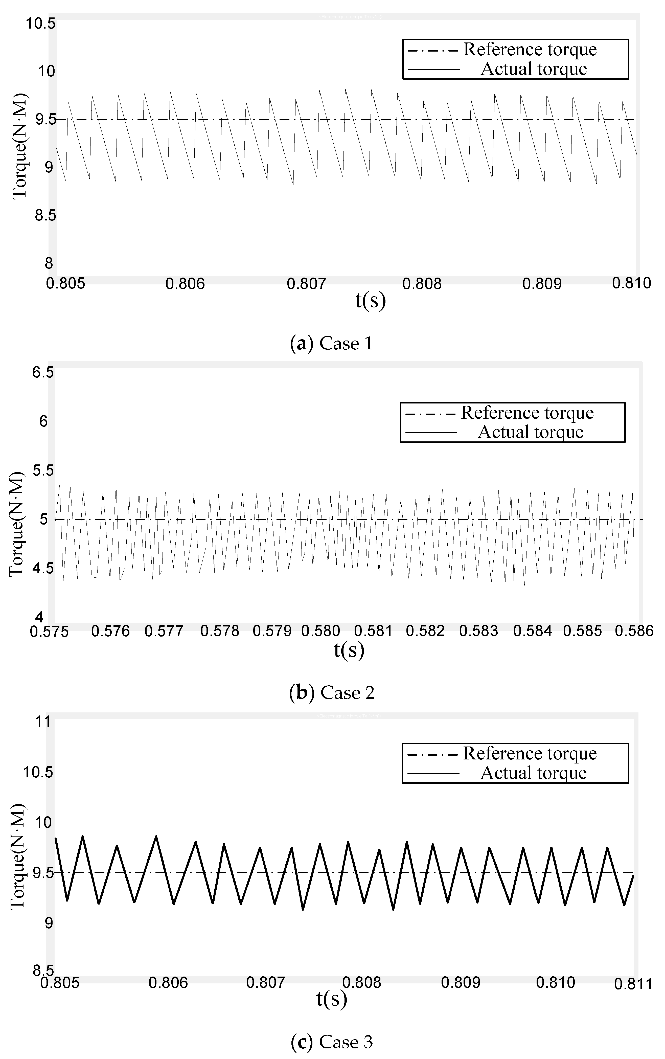
  • For the case shown in Figure 6a, portion above the torque command value to the maximum torque ripple value will decrease, while the portion below the command value will not change. However, in this case, the increase in torque is much slower than the decrease in torque. Hence, the reduction is limited, and the phenomenon of negative offset of average torque still exists.
  • For the case shown in Figure 6b, portion above the torque command value to the maximum torque ripple will reduce by about half of the amplitude before improvement, and the portion below the command value will remain unchanged. The total pulsation amplitude will be reduced to about 70% before improvement, and there will be a small negative offset of the average torque.
  • For the case shown in Figure 6c, portion above the torque command value to the maximum torque ripple value will greatly reduce. Although portion below the command value remains unchanged, the improved ripple amplitude will be very small because of the small reduction of zero vector to torque in this case. In addition, the original average torque positive bias will be reduced or even eliminated.
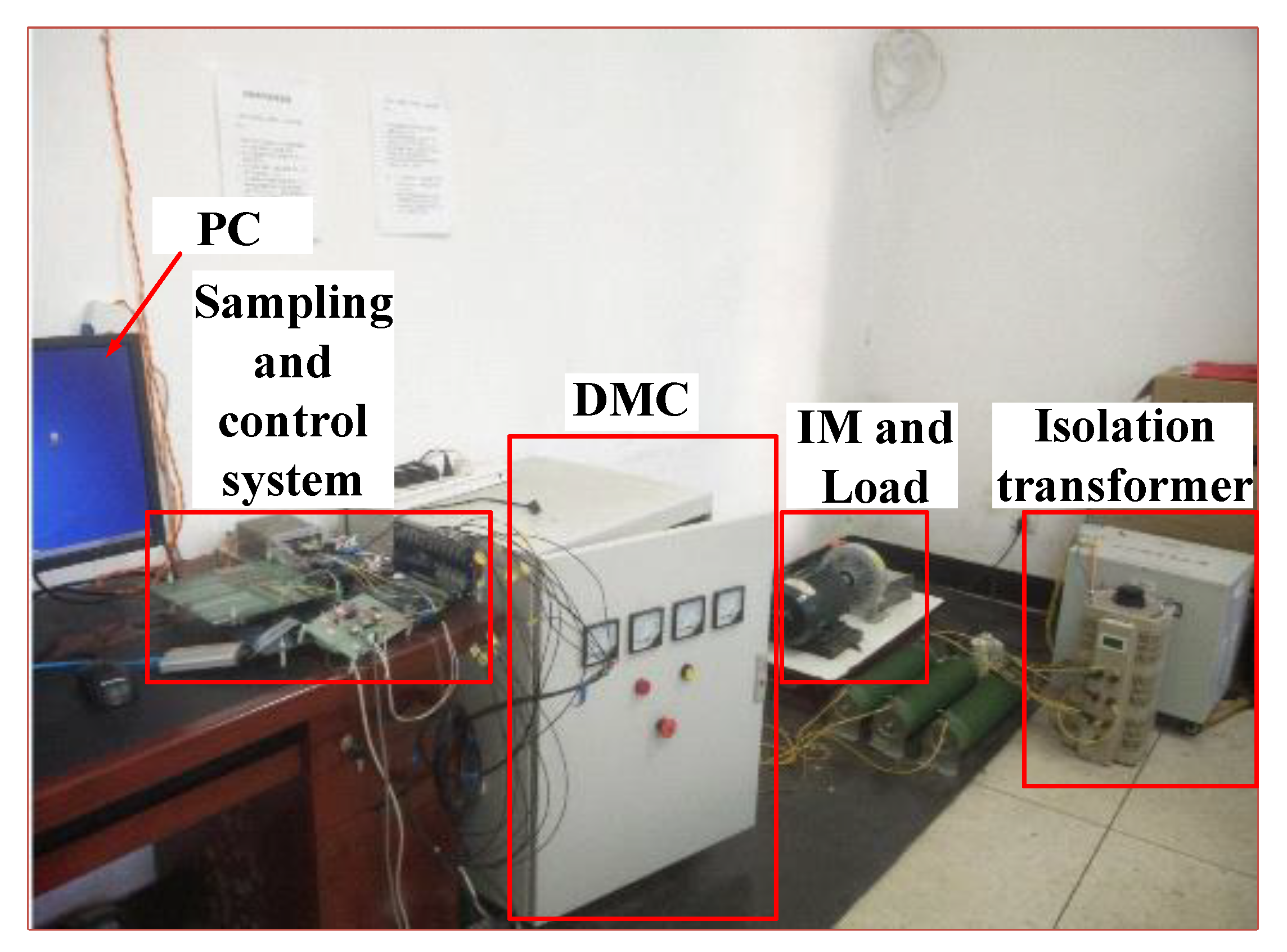
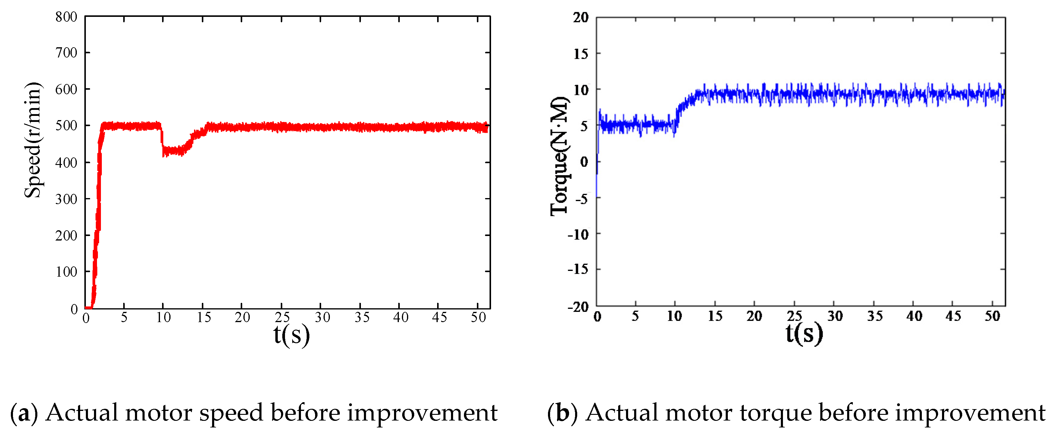
Figure 7 shows the simulation results in three cases after using the torque tracking algorithm. Compared with the results in Figure 6, it can be seen that performance improvement in the middle and low speed areas, especially in the low speed areas, is quite obvious. Not only is the torque ripple reduced, but the saw tooth wave is basically eliminated. However, the performance improvement in the high-speed areas after the improvement is not much. As the torque ripple has less effect on the high-speed performance of the system than that of the low-speed system, the performance of the whole system has been greatly improved after using the torque tracking algorithm. Figure 8 is a comparison diagram of simulation results of system torque characteristics. Figure 9a,b and Figure 10a,b are the comparison of the speed characteristics and torque characteristics of the motor before and after the improvement.
At the 10th second, increase the torque T = 10 N·M. In Figure 9, the conventional DMC-DTC motor speed response is slow, and the torque fluctuation is large. It can be seen from Figure 10 that after the torque tracking algorithm is adopted, the speed of the motor is identified quickly, and the torque fluctuation is also small, obviously improving the robustness of the entire system.

5. Experiment

This experiment mainly studies the influence of the torque tracking algorithm on the system torque and speed characteristics. The purpose is to verify whether the proposed improved algorithm is effective in practical applications.
Experiments were performed on a platform of a matrix converter drag asynchronous motor direct torque control system, and Figure 11 is structure block diagram of the DMC-DTC experimental system. The experimental platform is shown in Figure 12. Figure 13 shows the internal modular main circuit and drive circuit of DMC.
The entire experimental platform is mainly composed of three-phase input power, three-phase isolation transformer, voltage regulator, matrix converter experimental integrated device, digital signal processing control board (DSP) and field programmable gate array control board (FPGA), isolated power supply, filtering device, and other components. Among them, the main circuit of the matrix converter adopts busbar connection. Compared with the traditional wiring method, it has the characteristics of small stray inductance and strong anti-interference ability. The 18 PWM signal waves sent from FPGA are transmitted to the drive circuit through 18 optical fibers. Nine bidirectional switches work, which has the advantages of fast speed and reliable operation.
In order to verify the practicability and effectiveness of the strategy proposed in this paper, an experimental study was conducted on a 3 kW asynchronous motor. The parameters of this motor are shown in Table 4. In the experimental test platform, the load motor is a 6 kW induction motor. The load motor and the induction motor are coaxially connected through a coupling to provide a load for the asynchronous motor. The experimental results are shown in Figure 14, Figure 15, and Figure 16.
The standard deviation σ T e of torque is used to evaluate the output torque performance of the system, σ T e is defined as
{ σ T e = 1 N 1 k = 1 N ( T e ( k ) T e ¯ ) 2 T e ¯ = 1 N k = 1 N T e ( k )
where N is the number of samples and k is the k-th individual in the sample.
In order to make the comparison more clearly visible, the steady-state performance comparison of the motor is listed in Table 5. As shown in Figure 14a,b, the motor speed of traditional DTC fluctuates greatly and the robustness is poor. The torque of the motor reaches a steady state time of 0.7 s. Torque standard deviation of traditional DTC is 8.67 N·m. The load torque is suddenly increased to 10 N·m at 10 s. The sudden response time of the motor is 3.3 s. In Figure 14b, the system torque of traditional DTC still has large pulsation. In Figure 15a,b, the speed and torque ripple and fluctuation of the improved DTC system are relatively small. The torque of the motor reaches a steady state time of 0.5 s. Torque standard deviation of improved DTC is 4.93 N·m. The load torque is suddenly increased to 10 N·m at 10s. The sudden response time of the motor is 2.1 s. From the comparison results of Figure 14 and Figure 15, the proposed torque improvement algorithm has a more obvious effect on reducing the torque and speed ripples.
From the comparison results in Figure 16, the current THD of the traditional DTC is 15.74%, and the current THD of the improved DTC is 9.65%. This means that the torque and flux ripple will be reduced. The system performance will be improved.

6. Conclusions

The torque ripple is analyzed in detail, and an improved method of torque tracking control is proposed. During the period of non-zero working vector action, this control strategy adjusts the non-zero vector and zero vector action time appropriately to reduce the torque ripple. Simulation and experimental results show that:
(1)
The output power factor of the DMC-DTC system is high.
(2)
The system torque response is rapid, direct torque control has the advantages of simple rules, direct control means, and rapid torque response. However, the control performance is still insufficient in some aspects.
(3)
An in-depth theoretical analysis of the above-mentioned performance defects and the causes of such deficiencies were carried out, and an improved method of torque tracking control was proposed to reduce torque ripple.
(4)
The quality of the output current waveform of the system is improved, and the harmonic content is less. The matrix converter-direct torque control system proposed and implemented in this paper has a simple structure and clear ideas. It has laid a good foundation for the development of high-performance frequency conversion speed control system.

Author Contributions

Conceptualization and methodology, B.Z. and Y.G.; Software, B.Y. and X.W.; Validation, B.Z. and Y.G.; Writing—original draft preparation, B.Z.; Writing—review and editing, B.Z. and Y.G.; Supervision, X.X., M.S., and Y.T.; All authors have read and agreed to the published version of the manuscript.

Funding

This research received no external funding.

Conflicts of Interest

The authors declare no conflict of interest.

References

  1. Mondal, S.; Kastha, D. Input Reactive Power Controller with a Novel Active Damping Strategy for a Matrix Converter Fed Direct Torque Controlled DFIG for Wind Power Generation. IEEE J. Emerg. Sel. Top. Power Electron. 2019. [Google Scholar] [CrossRef]
  2. Gontijo, G.; Soares, M.; Tricarico, T.; Dias, R.; Aredes, M.; Guerrero, J. Direct Matrix Converter To-pologies with Model Predictive Current Control Applied as Power Interfaces in AC, DC, and Hybrid Microgrids in Islanded and Grid-Connected Modes. Energies 2019, 12, 3302. [Google Scholar] [CrossRef] [Green Version]
  3. Tuyen, N.D.; Dzung, P.Q. Space vector modulation for an indirect matrix converter with improved input power factor. Energies 2017, 10, 588. [Google Scholar] [CrossRef] [Green Version]
  4. Rodriguez, J.; Rivera, M.; Kolar, J.W.; Wheeler, P.W. A Review of Control and Modulation Methods for Matrix Converters. IEEE Trans. Ind. Electron. 2012, 59, 58–70. [Google Scholar] [CrossRef]
  5. Bak, Y.; Lee, E.; Lee, K.B. Indirect matrix converter for hybrid electric vehicle application with three-phase and single-phase outputs. Energies 2015, 8, 3849–3866. [Google Scholar] [CrossRef]
  6. Xu, L. Research on the Amplitude Coefficient for Multilevel Matrix Converter Space Vector Modulation. IEEE Trans. Power Electron. 2012, 27, 3544–3556. [Google Scholar]
  7. Bao, G.Q.; Qi, W.G.; He, T. Direct Torque Control of PMSM with Modified Finite Set Model Predictive Control. Energies 2020, 13, 234. [Google Scholar] [CrossRef] [Green Version]
  8. Lee, J.S. Stability Analysis of Deadbeat-Direct Torque and Flux Control for Permanent Magnet Synchronous Motor Drives with Respect to Pa-rameter Variations. Energies 2018, 11, 2027. [Google Scholar] [CrossRef] [Green Version]
  9. Yan, Y.; Zhao, J.; Xia, C.; Shi, T. Direct torque control of matrix converter-fed permanent magnet synchronous motor drives based on master and slave vectors. IET Power Electron. 2015, 8, 288–296. [Google Scholar] [CrossRef]
  10. Karlovsky, P.; Lettl, J. Induction motor drive direct torque control and predictive torque control comparison based on switching pattern analy-sis. Energies 2018, 11, 1793. [Google Scholar] [CrossRef] [Green Version]
  11. Park, J.B.; Wang, X. Sensorless direct torque control of surface-mounted permanent magnet synchronous motors with nonlinear Kalman filtering. Energies 2018, 11, 969. [Google Scholar] [CrossRef] [Green Version]
  12. Liu, Q.; Hameyer, K. Torque Ripple Minimization for Direct Torque Control of PMSM With Modified FCSMPC. IEEE Trans. Ind. Appl. 2016, 52, 4855–4864. [Google Scholar] [CrossRef]
  13. Ameur, A.; Mokhtari, B.; Essounbouli, N.; Mokrani, L. Speed sensorless direct torque control of a pmsm drive using space vector modulation based mras and stator resistance estimator. Variations 2012, 1, 5. [Google Scholar]
  14. Xia, C.; Wang, S.; Wang, Z.; Shi, T. Direct Torque Control for VSI–PMSMs Using Four-Dimensional Switching-Table. IEEE Trans. Power Electron. 2016, 31, 5774–5785. [Google Scholar] [CrossRef]
  15. Naik, N.V.; Panda, A.; Singh, S.P. A Three-Level Fuzzy-2 DTC of Induction Motor Drive Using SVPWM. IEEE Trans. Ind. Electron. 2016, 63, 1467–1479. [Google Scholar] [CrossRef]
  16. Abosh, A.H.; Zhu, Z.Q.; Ren, Y. Reduction of Torque and Flux Ripples in Space Vector Modulation-Based Direct Torque Control of Asymmetric Permanent Magnet Synchronous Machine. IEEE Trans. Power Electron. 2017, 32, 2976–2986. [Google Scholar] [CrossRef]
  17. Zhao, S.; Yu, H.; Yu, J.; Shan, B. Induction motor DTC based on adaptive SMC and fuzzy control. In Proceedings of the 27th Chinese Control and Decision Conference (2015 CCDC), Qingdao, China, 23–25 May 2015; pp. 4474–4479. [Google Scholar] [CrossRef]
  18. Jang, Y.; Bak, Y.; Lee, K. Indirect Matrix Converter for Permanent-Magnet-Synchronous-Motor Drives by Improved Torque Predictive Control. In Proceedings of the 2018 International Power Electronics Conference (IPEC-Niigata 2018 -ECCE Asia), Niigata, Japan, 20–24 May 2018; pp. 1736–1740. [Google Scholar] [CrossRef]
Figure 1. Topology of direct matrix converter.
Energies 13 03247 g001
Figure 2. Voltage current vectors of direct matrix converter.
Energies 13 03247 g002
Figure 3. Block diagram of DMC-DTC control system.
Energies 13 03247 g003
Figure 4. Schematic diagram of torque fluctuation.
Energies 13 03247 g004
Figure 5. Torque pulsation diagram under different speeds and loads.
Energies 13 03247 g005
Figure 6. Torque ripple simulation results: dotted line: reference torque; solid line: actual torque.
Energies 13 03247 g006
Figure 7. Torque ripple of the improved system: Dotted line: reference torque; Solid line: actual torque.
Energies 13 03247 g007
Figure 8. Comparison of simulation torque characteristics.
Energies 13 03247 g008
Figure 9. Motor speed characteristics and torque characteristics before improvement.
Energies 13 03247 g009
Figure 10. Improved motor speed characteristics and torque characteristics.
Energies 13 03247 g010
Figure 11. DMC-DTC experimental system structure block diagram.
Energies 13 03247 g011
Figure 12. Experimental platform.
Energies 13 03247 g012
Figure 13. The internal modular main circuit and drive circuit of the DMC.
Energies 13 03247 g013
Figure 14. Speed dynamic and torque dynamic responses before improvement.
Energies 13 03247 g014
Figure 15. Improved speed dynamic and torque dynamic responses.
Energies 13 03247 g015
Figure 16. Comparison of motor current before and after improvement.
Energies 13 03247 g016
Table 1. Output voltage space vector selection table of matrix converter
C Ψ C T Sector
−1−1U2U3U4U5U6U1
0U7U0U7U0U7U0
1U6U1U2U3U4U5
1−1U3U4U5U6U1U2
0U0U7U0U7U0U7
1U5U6U1U2U3U4
Table 2. Switch table of DMC-DTC control system.
S v i Sector
Sin1−11−11−11−11−11−1
U1−312−3−123−1−231−2
U29−7−897−8−978−9−78
U3−645−6−456−4−564−5
U43−1−231−2−312−3−12
U5−978−9−789−7−897−8
U66−4−564−5−645−6−45
Table 3. DMC-DTC simulation parameters
VariableParametersValue
PNRated power3 kW
UNRated voltage380 V
RsStator resistance0.2 Ω
RsStator inductance2.2 mH
RrRotor resistance0.42 Ω
LrRotor inductance2.2 mH
LmMutual inductance1.56 mH
npPole pairs of motor2
Table 4. Motor parameters of experiment
VariableParametersValue
PNRated power3 kW
UNRated voltage380 V
RSStator resistance0.2 Ω
LSStator inductance2.2 mH
RrRotor resistance0.42 Ω
LrRotor inductance2.2 mH
LmMutual inductance1.56 mH
npPole pairs of motor2
nNRated speed1430 r/min
TN20N·m
Table 5. Comparison of steady state performance of the motor.
Control MethodTorque Response TimeTorque Standard Deviation ( σ T e )Mutation Response TimeTHD of Motor Current
Traditional DTC0.7 s8.67 N·m3.3 s15.74%
Improved DTC0.5 s4.93 N·m2.1 s9.65%

