Article

Bidirectional Coupling Model of Electromagnetic Field and Thermal Field Applied to the Thermal Analysis of the FSPM Machine

1
School of Electrical Engineering, Southeast University, No. 2 Si Pai Lou, Nanjing 210096, China
2
State Key Laboratory of Air-conditioning Equipment and System Energy Conservation, Zhuhai 519070, China
*
Author to whom correspondence should be addressed.
These authors contributed equally to this work.
Energies 2020, 13(12), 3079; https://doi.org/10.3390/en13123079
Submission received: 10 May 2020 / Revised: 7 June 2020 / Accepted: 11 June 2020 / Published: 14 June 2020
(This article belongs to the Section F: Electrical Engineering)

Abstract

:
The paper aimed to find an accurate and fast model to study the electromagnetic (EM) thermal (TH) filed coupling calculation for the TH analysis in the flux switching permanent magnet (FSPM) machine. It is extremely important to know the coupling mechanism between the EM field and TH field for the designers and users of the FSPM machines. Firstly, in order to study the EM properties of the silicon steel sheet with the temperature, the Epstein frame experiment was set up, where the effect of dc magnetic bias on the core loss is also considered. In order to save the computation time, the bidirectional coupling model based on 2D finite element (FE) EM field and 3D asymmetric minimum element TH field is established, and the steady state and transient TH fields are calculated, respectively. For the transient bidirectional coupling of EM field and TH field, a method based on the adaptive adjustment calculation step is adopted to improve the computing speed. The temperature rise experiment of the prototype was carried out to verify the accuracy of the proposed coupling model. The experimental results are in good agreement with the simulation results.

Graphical Abstract

1. Introduction

Due to the advantages of simple salient structure, easy cooling, and high torque density [1], flux switching permanent magnet (FSPM) machines have been extensively researched on the field of the wind power generation [2] and electrical vehicles [3,4]. When the FSPM machines rotate, they are under tight coupling of multi-physics such as electromagnetic (EM) field and thermal (TH) field. In FSPM machines, the permanent magnets (PMs) are placed on the stator side and in the middle of the armature windings with concentrated EM losses. These EM losses are the heat sources in the TH field, while the temperature in turn affects the performance of the EM materials of the FSPM machines. For example, when the temperature rises, the conductivity of the copper windings descend and the loss increases, which in turn causes the temperature to rise. Therefore, to keep the machines operating within the safe temperature range and maintain the maximum torque output, a bidirectional coupled model between the EM field and TH field is needed for the machines’ designers.
However, to the best of our knowledge, the coupling model between 2D EM field and 3D asymmetric minimum element TH field has not been derived. Because the coupling mechanism between the EM field and TH field is very important for the TH analysis, there have been many scholars who have studied the coupling model for the EM field and TH field of the electrical machines over the past few decades. It is well known that the time constant of the TH field is much longer than that of the EM field, sometimes more than 10τ times. Because of the larger difference of the time constants between the two fields, the weak coupled model between the EM field and TH field is established in [5]. In order to study the EM properties of the induction motor, the coupled model between the EM finite element analysis (FEA) and the TH resistance network (TRN) is built in [6]. Due to the merits of the fast calculation speed and the easy-to-understand principle, the TRN has been used for the temperature rise of the electrical machines. However, the TH distribution of the machines cannot be obtained by the TRN method. Thanks to the use of commercial software such as Comsol Multiphasic, the 3D coupling model between the EM field, TH field, and fluid field is built for the TH analysis of the axial flux PM synchronous machines in [7]. However, this method needs a large number of grids and takes a long time to complete the computation. In order to solve the problem of data transfer between different fields, the FEA model for the EM field, TH field, and mechanical field for the dual-mechanical port machine has been built [8], where the grids of different fields are the same. In [8], the models for the EM field, TH field, and mechanical field are built based on the 2D FEA, where the heat conduction along the axial direction is ignored and this will lead to significant error. In general, the temperature in the axial direction in the electrical machines is not equal, so there will be heat flow in the axial direction. In addition, the EM 2D transient FEA model coupled with the TH 3D static FEA model is established for the electrical machines [9]. These two fields are coupled together by the data transfer and the convergence condition is reached by iteration. In this method, the 3D TH model is built based on the full model, which will result in a large number of grids and increase the computation burden. In [10], the lumped parameter steady TH model and FEA 3D steady TH model are used for the TH analysis for the double rotor FSPM machine. Although the temperature results obtained by the two temperature models are close to that obtained by the temperature rise tests, the EM field and TH field are not coupled in this paper. In [11], the concept of the bidirectional coupling model based on 2D EM field and 3D asymmetric minimum element TH field was proposed. The temperature distribution with considering the EM and TH fields coupling analysis is compared with that without considering the two fields coupling. Although this method has reduced many calculation meshes and saved computing time compared with the traditional methods, the time step is a constant in this method, especially when the temperature is about to reach steady state, the temperature difference between the two adjacent calculation is very small. So it will take plenty of calculation time to ensure the temperature reaches the steady state.
In the EM field, the core loss should get special consideration. From an engineering point of view, iron loss is considered to be composed of hysteresis loss, eddy current loss, and excess losses, which is only an empirical formula that considers iron loss as a function of magnetic density amplitude, frequency, and temperature, rather than a direct explanation of physical phenomena [12]. For the FSPM machines, there exists the dc magnetic bias in the rotor tooth, stator tooth, and yoke, increasing the core loss [13]. Therefore, it is very important to find the relationship between dc magnetic bias and core loss. However, these parameters are not supplied by the core manufacturer and need to be measured.
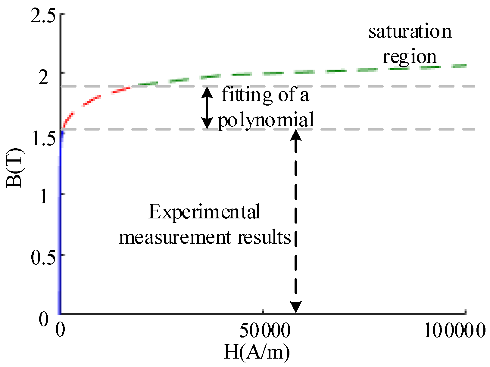
In order to obtain the parameters of the core loss which are related to temperature, the Epstein frame experiment is first established in this paper, where the effect of dc magnetic bias is also considered. In addition, the B–H curves at different temperatures are also measured. Due to the limitation of experimental equipment, the maximum flux density can only be measured up to 1.4 T, and then the B–H values in the saturated region are fitted by extrapolation method. Then, the steady state and transient TH analysis using the bidirectional coupled model of the 2D EM field and 3D asymmetric minimum element TH field are conducted. The steady state TH analysis is known to be very fast. For transient TH analysis using the bidirectional coupled model of the EM and TH fields, a method of adaptive adjustment time step is used to improve the computing speed. At last, the temperature rise experiment is carried out to testify the accuracy of the model proposed in this paper. The results show that the proposed model not only has high accuracy, but also can realize the fast coupling calculation.

2. Thermal (TH) Properties of Electromagnetic (EM) Materials

A FSPM machine is composed of PMs, stator core, rotor core, windings, and housing. For the prototype studied in this paper, the material of the stator/rotor core, PMs, and housing are 35WW300, N35SH, and Aluminum, respectively. The windings are made of copper, copper insulation, and impregnated/filled material. The TH conductivity of these materials has been given in detail in [14]. This paper mainly gives the EM properties dependent on the TH of these materials.

2.1. Silicon Steel Sheet

Although core loss accounts for a large proportion of the total loss in the electrical machines [15] and the influence of temperature on core loss is very obvious [16], parameters of the core loss are difficult to find. Many manufacturers did not provide these data before, so it is necessary to carry out the core loss experiments under different temperatures. The materials of stator core and rotor core used in this paper is 35WW300. Firstly, the Epstein frame experiment platform is established, as shown in Figure 1. A thermo tank is used to make sure that the silicon steel sheet is kept at the specified temperature. The programmable ac power supply is used to input the ac voltage or dc + ac voltage to the excitation winding. The current of the excitation winding and the voltage of the measuring winding are recorded by the oscilloscope.
According to the measured current of excitation winding and the measured voltage of measuring winding, the magnetic flux density and field strength can be obtained by,
ϕ ( t ) = 1 N m 0 t e 2 ( t ) d τ
ϕ m ( t ) = ϕ ( t ) 1 T i 0 T i ϕ ( t ) d t
B ( t ) = ϕ m ( t ) S e
H e ( t ) = N e i ( t ) L e
where Nm and Ne are coil turns of the measuring winding and excitation winding, respectively. Ti is time period. e2 is the voltage of the measuring winding, and i(t) is the current of the excitation winding. Se and Le are the total cross-sectional area and the total length of the core under test.
The loss PFe of the core under test can be obtained by,
P F e = 1 ρ c o r e V e T 0 T i i ( t ) e 2 ( t ) d t
where ρcore and Ve are the density and total volume of the core under test.

2.1.1. Coefficients of Core Loss Under AC Excitation

From an engineering point of view, core loss is considered to be composed of hysteresis loss, eddy current loss, and additional loss. However, the calculated additional losses are small and sometimes negative due to the limitation of experimental equipment. Therefore, core loss is usually divided into hysteresis loss and eddy current loss. The coefficients of hysteresis loss and eddy current loss are related to the magnetic flux density amplitude, frequency and temperature. Since the frequency of this prototype under research is 166.7 Hz, the B–H curves within the range of 50~400 Hz have been tested by Epstein frame, and the loss coefficients are considered to be independent of frequency within this frequency range. Then, the core loss can be obtained by,
p F e = K h ( B m , T ) f B m 2 + K e ( B m , T ) f 2 B m 2
where Kh(Bm, T) and Ke(Bm, T) are the hysteresis loss coefficient and eddy current loss coefficient, respectively. Bm is the magnetic flux density amplitude, and f is the test frequency. T is the current temperature.
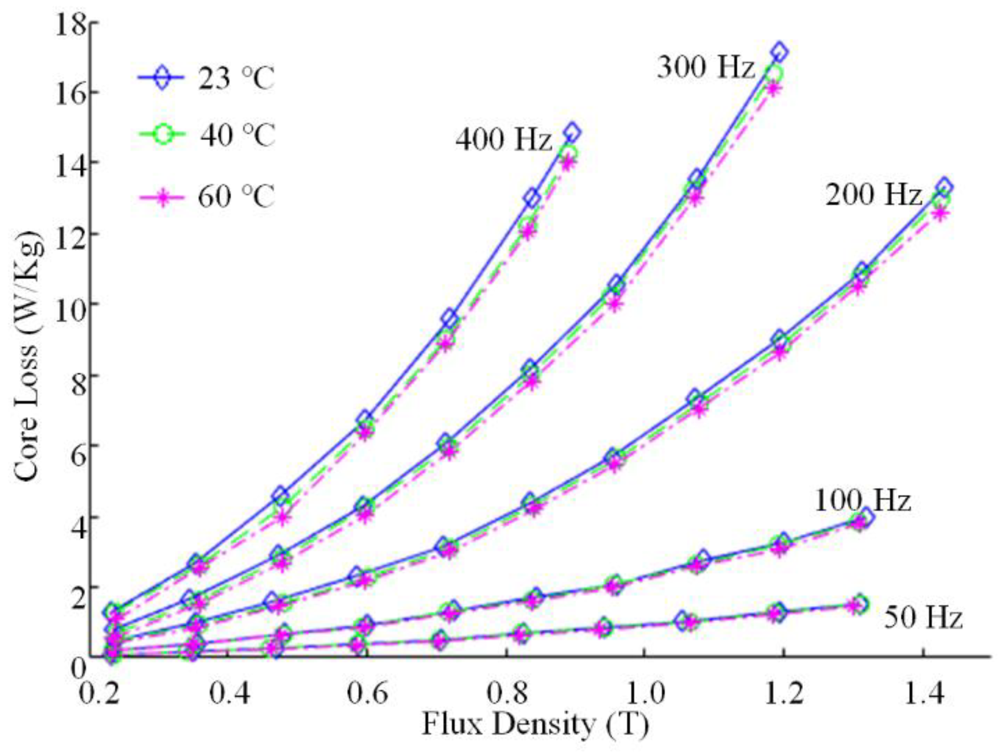
Figure 2 gives the core losses at different magnetic flux density amplitudes, different temperatures, and different frequencies. The core loss is positively correlated with magnetic flux density amplitude and frequency, and inversely correlated with temperature.
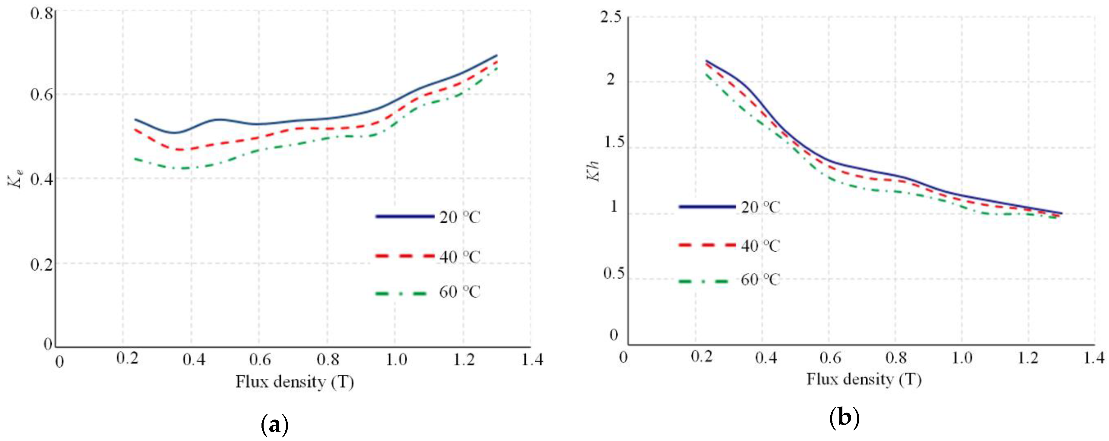
Based on (6) and the data in Figure 2, the loss coefficients Ke and Kh at different flux density amplitudes and temperatures could be calculated as shown in Figure 3. Both coefficients Ke and Kh decrease when the temperature increases.

2.1.2. Coefficients of Core Loss Considering DC Magnetic Bias

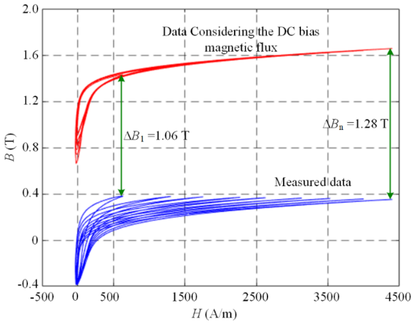
In FSPM machines, the main reason for dc magnetic bias in the stator core is that the PMs are placed on the stator side. In addition, because stator core is slotted, there are small hysteresis loops in the rotor tooth [13,14]. It is reported that the core loss will increase when there exists the dc magnetic bias. However, it is difficult to find the core loss coefficients when considering dc magnetic bias. Therefore, the Epstein frame test with the ac + dc power supply is conducted in this section. Figure 4 gives the B–H curves obtained by the dc bias magnetic flux experiment when the flux density is 0.25 T and the frequency is 200 Hz. The blue lines are obtained by the experiment directly, while the red lines are the calculated B–H curves with considering the dc bias magnetic flux. The results of the dc bias magnetic flux can be obtained by comparing the red and the blue B–H curves. The core loss considering the dc magnetic bias can be obtained by the calculating the B–H curves’ area.
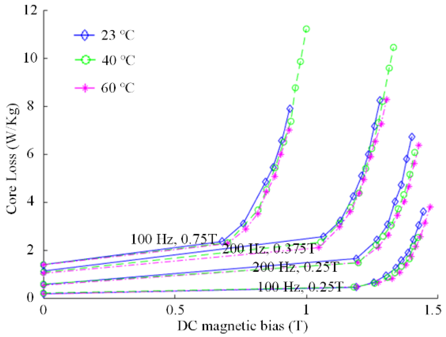
The core losses of the silicon steel sheet under different magnetic flux density amplitudes, different frequencies and different dc magnetic biases are measured, as shown in Figure 5. The core loss increases with the increase of the value of dc magnetic bias and with the decrease of the values of the temperature.
It is assumed that dc magnetic bias only affects the hysteresis loss and not eddy current loss. It is found that the increased core loss due to the dc magnetic bias is independent of the amplitude and the frequency of the magnetic density [13]. The relation between the hysteresis loss pFe_h and dc magnetic bias is
p F e _ h = ε ( Δ B ) K h ( T ) f B m 2
ε ( Δ B ) = 1 + k d c ( T ) Δ B β ( T ) + k l ( T ) Δ B 2
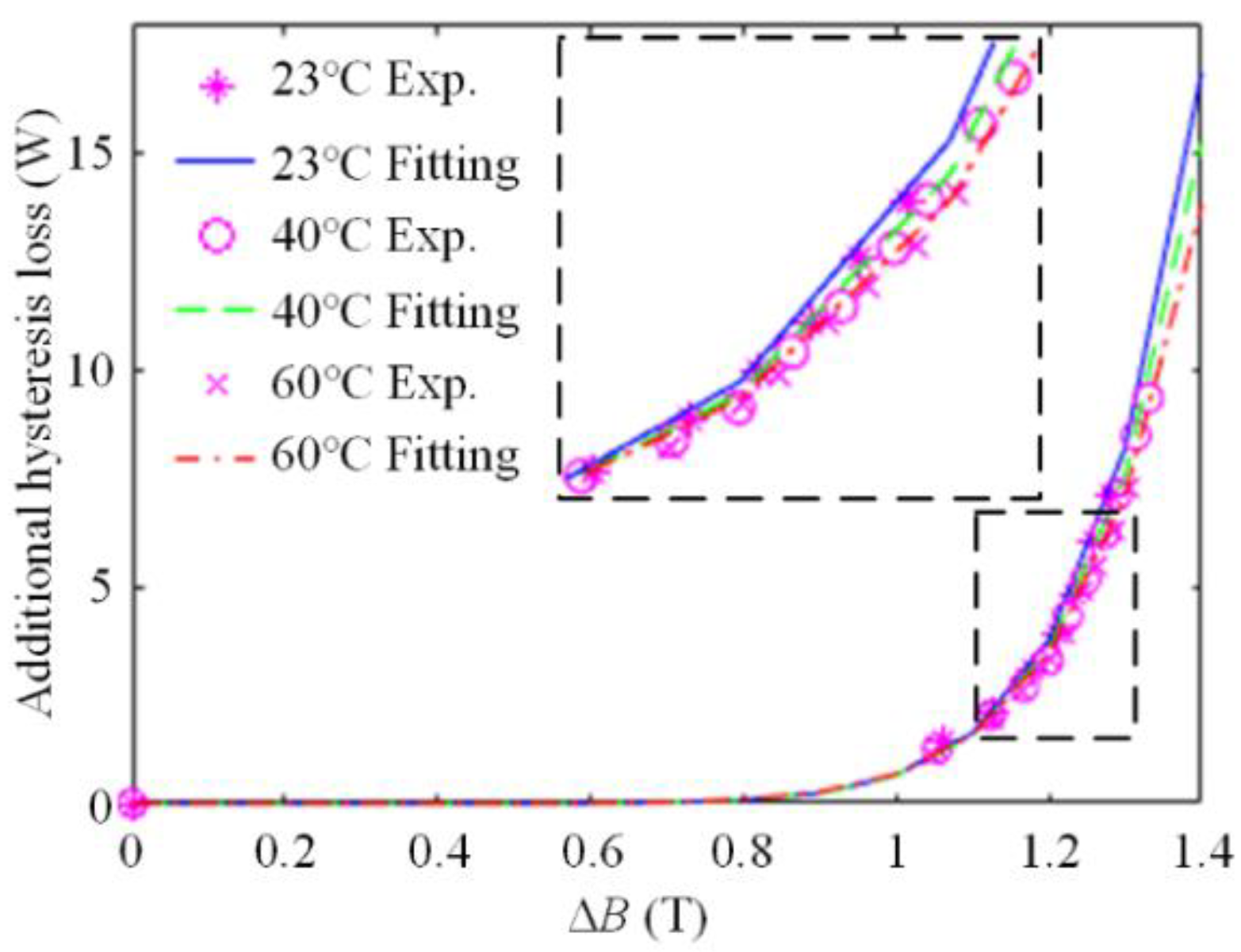
where kdc(T), β(T), and kl(T) can be calculated by the data fitting, and it is assumed that these coefficients are linear functions of temperature.
In this paper, the increased hysteresis loss Phin due to the dc magnetic bias can be defined as,
p h i n = k d c ( T ) Δ B β ( T ) + k l ( T ) Δ B 2
Figure 6 shows the loss of the core under test at different values of the dc magnetic bias and different temperatures with the alternating frequency of 200Hz and the magnetic density amplitude of 1.0 T. It can be seen that the core loss calculated by Equation (9) is in good agreement with the results obtained by the experiments.

2.1.3. Mathematical Model of Silicon Steel Sheet B–H Curve

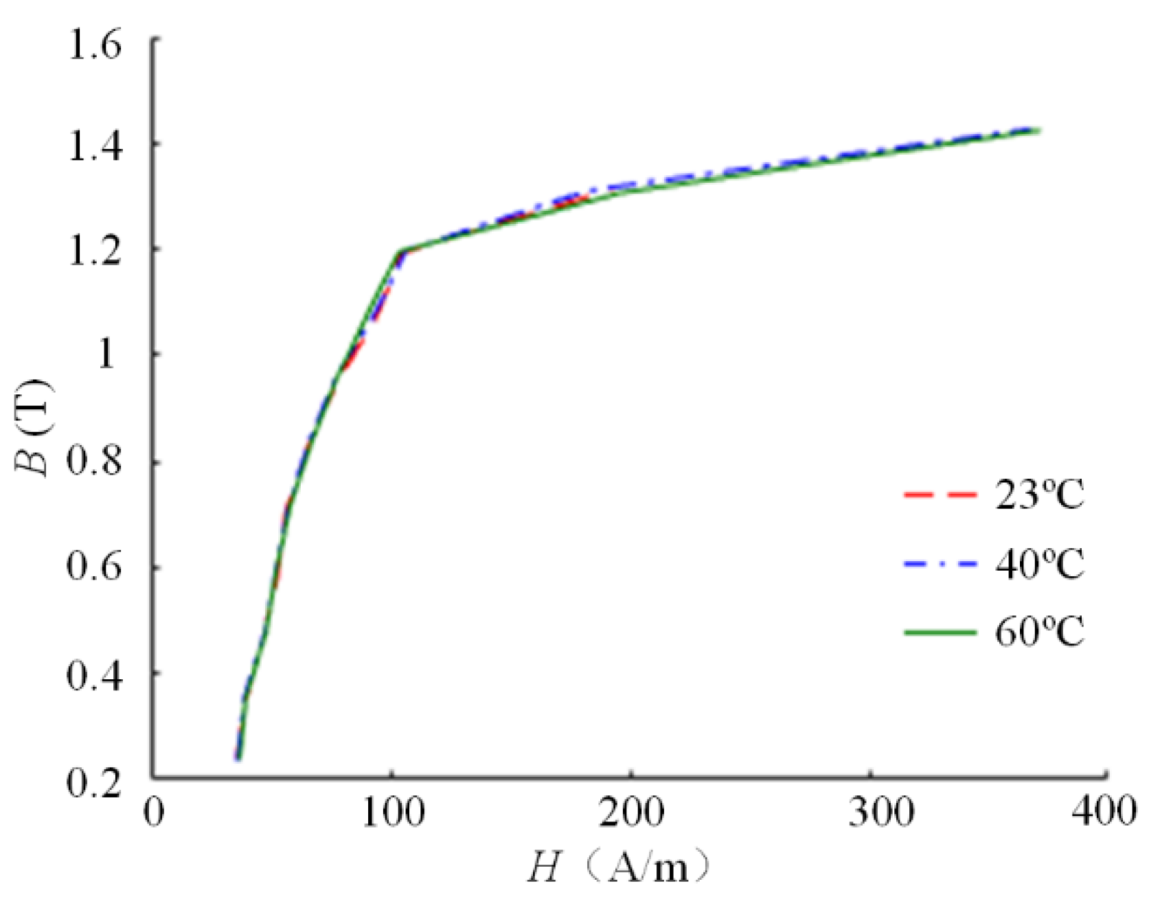
Due to the limitations of the experimental equipment, the maximum magnetic density measured does not exceed 1.6 T, as shown in Figure 7 indicating that the temperature has no influence on the B–H curves. However, two PMs of the FSPM machines are adjacent to produce a strong magnetic density. When the rotor is in some position, the magnetic density of stator tooth tip and rotor tooth tip can reach more than 2.0 T. Therefore, extrapolation method should be used to estimate the oversaturated region of B–H curve. When the flux density amplitude is larger than 1.6 T and smaller than saturated flux density Bs, an extrapolation polynomial is usually used to obtain the B–H curves, which is shown as follows,
H = i = 0 n B i β i
where βi is the extrapolation coefficient dependent on the n+1 test data, and n represents the polynomial order.
However, the wide flus density range cannot be obtained only by the extrapolation of the B–H curve using (10), because the error will become large when the magnetic flux density in the core under test is larger than the saturated flux density Bs [17]. When the flux density of the core under test reaches saturation, the direction of all magnetic domains in the core under test are the same with the direction of the applied magnetic field. Besides, the magnetic permeability of the core under test and air are the same at this time, monomial extrapolation is adopted.
B = μ 0 H + 1.935
where μ0 represents the permeability of the air.
Above all, the B–H curve obtained by extrapolation is shown in Figure 8.

2.2. Permanent Magnet

The material of PMs used in this paper is N35SH, whose performance mainly depends on the remanence Br, relative permeability μr, and intrinsic coercivity Hci. It is known that the remanence Br and intrinsic coercivity Hci of the PM will decrease as the temperature of the PM increases, and if the working point of the PMs is lower than the knee point, the PM will be partially demagnetized. However, the difficulty of the calculation procedure will be significantly increased if the partial demagnetization of the PM is accurately described. In this paper, in order to save computation time, the influence of demagnetization and TH on the remanence Br and intrinsic coercivity Hci of the PMs is not considered. Only the influence of the TH on the conductivity σPM of the PM is considered, which can be expressed as,
σPM = σPM0 × (1 − αPM(T − 20))
where σPM0 = 5.56e + 5 S/m when the temperature is 20 °C. αAl is the temperature coefficient of the PM.

2.3. Copper Windings

Electric conductivity of windings (σCu) varies with temperature. The value σCu0 = 5.9773e + 07 S/m at 20 °C yields a phase resistance of 0.03 Ω for the machine invested in this paper. The relationship of copper conductivity and temperature is as follows:
σCu = σCu0 × (1 − αCu(T − 20))
where αCu is the temperature coefficient of copper.

2.4. Aluminum Housing

When the motor is in the rotating state, eddy current will be induced in the housing due to the presence of magnetic flux leakage and conductivity of the aluminum housing, resulting in eddy current loss. The relationship between the conductivity of the Aluminum and temperature is:
σAl = σAl0 × (1 − αAl(T − 20))
where σAl is the aluminum conductivity and αAl is the temperature coefficient of aluminum. σAl0 = 3.7665e + 07 S/m when the temperature is 20 °C.

3. Bidirectional Couple between 2D EM Field and 3D TH Field

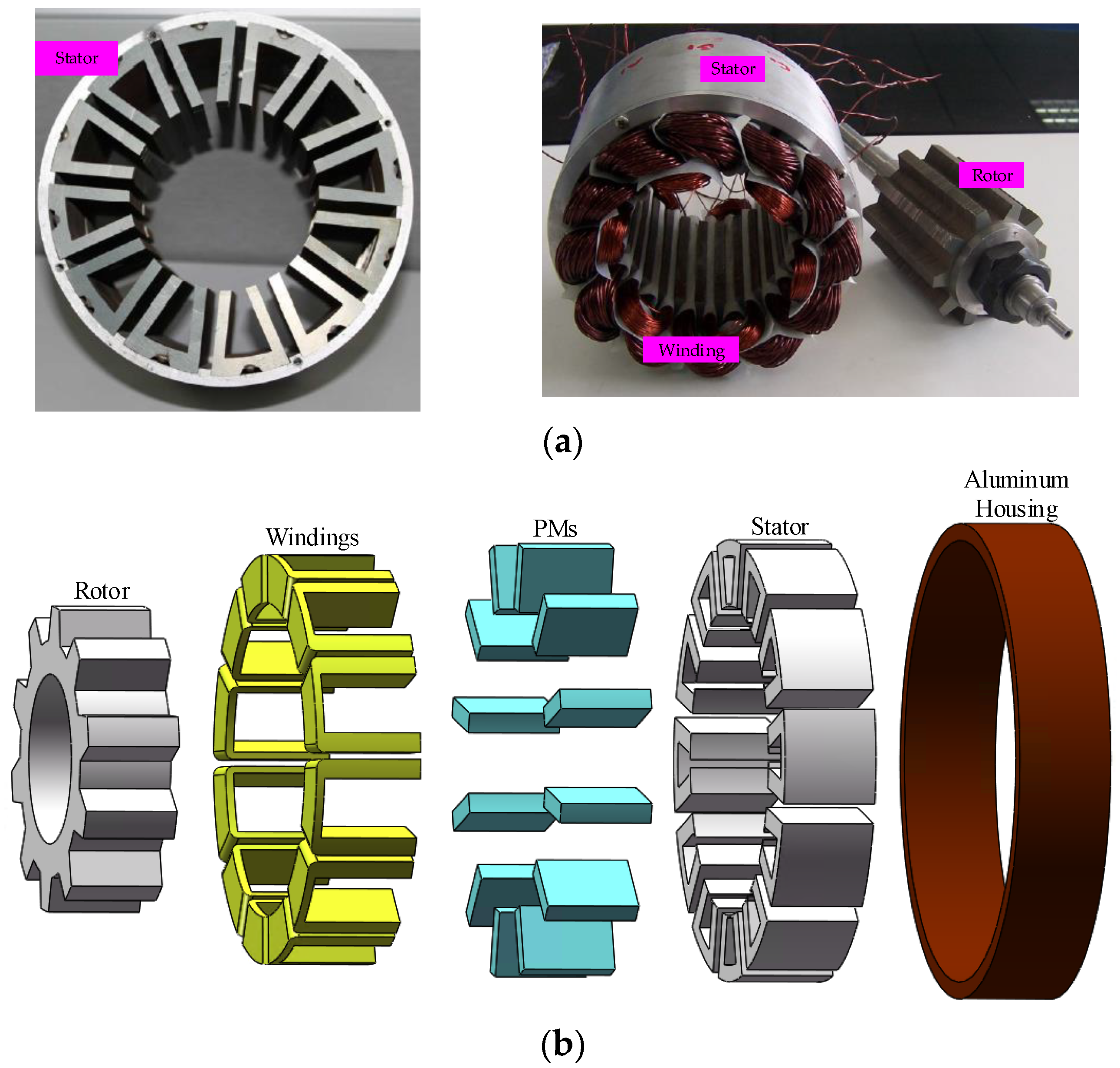
The electrical machine researched is 12/10 FSPM machine, whose structure diagram is given in Figure 9. Both the stator and the rotor are salient structures, and the armature windings and PMs are placed in the stator side. Figure 10 shows the assembling diagram of 12/10 FSPM machine. The stator is composed of 12 U-shape iron cores and the rotor contains 10 teeth. The prototype is a three phase machine containing twelve magnets, with each phase composed of four magnets and four concentric coils. The PMs are placed in the stator side and in the middle of the adjacent armature windings. Table 1 gives the main dimensions and performance parameters of the FSPM machine.
Since the time constants of the temperature field and the EM field are quite different, it is not necessary to strongly couple the EM field with the temperature field. In order to save the calculation time, the bidirectional coupling model based on the 2D EM field and 3D asymmetric minimum element TH field are built.

3.1. EM Field Model

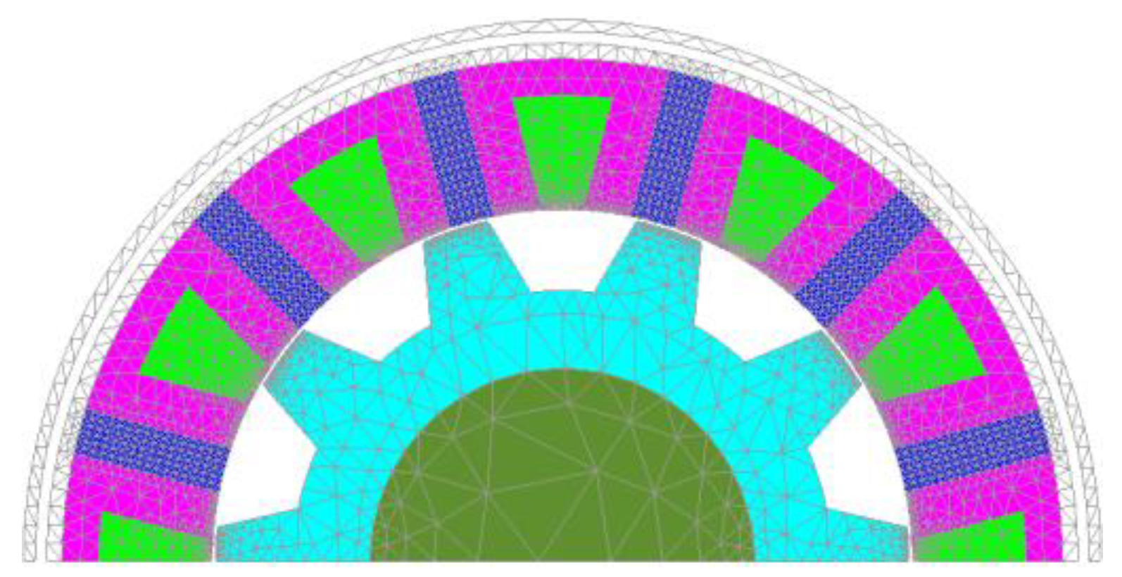
In order to reduce the computation burden, only a half model of the FSPM machine is built according to the periodic boundary for the 2D FEA EM field, which is shown in Figure 11. The initial position of the rotor is shown in Figure 11.
The governing equation and boundary conditions of EM field are as follows:
r o t ( 1 μ r o t A ) = σ ( A t g r a d V ) + J s + r o t H c
A z | S 1 = 0
H t | S 2 = 0
A | S s i d e = A | S l i n k
where A is the axial component of magnet vector potential. V is the voltage difference of the two ends of the electrical conductors. Js is the current density. Hc is the initial intrinsic coercivity.
In EM field analysis, PMs are considered to be electrical conductors, and the sum of currents in the section perpendicular to the axial direction is zero. The PM and Al housing eddy current loss can be calculated by the method proposed in [18].
It has been proved that there exists dc magnetic bias for the stator and rotor silicon steel sheet [13,14]. The parameters of core loss have been obtained in Section II. The accurate core loss model has been proposed in [14], which can be directly used for the core loss calculation of the prototype in this paper.
In the EM field analysis, the constant current source is applied to the machine. The copper loss can be calculated by multiplying the resistance of the windings and the square of the current.
Due to the low speed of the motor, the wind mill loss is ignored. In addition, the FSPM machine also has the mechanical loss on the rotating shaft, which is considered to be a constant by the experimental verification.

3.2. TH Field Model

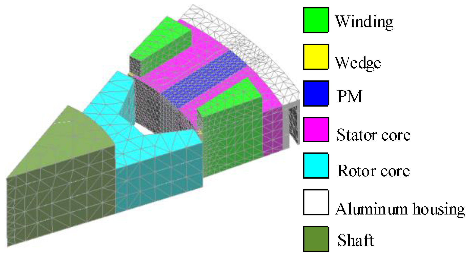
For the TH field, the 3D FEA model is considered to be the most accurate. However, the large amount of 3D FEA meshes increase the computation time. In order to save calculation time, the asymmetric minimum TH element of the stator and rotor is applied in the TH analysis [15]. Besides, 1/24 stator and 1/20 rotor model are established when considering the axial symmetry of temperature distribution, as shown in Figure 12.
The governing equation of the TH field is as follows:
Ω ρ c T t δ T d Ω = Ω ( λ x T x T x + λ y T y T y + λ z T z T z ) d Ω Γ h ( T T b ) δ T d Γ + Ω Q δ T d Ω
where ρc is the specific heat capacity of the material. T is the temperature of the mesh. λx, λy, and λz are the TH conductivities of each main direction in the element mesh, respectively. Tb is the ambient temperature for the convective heat dissipation boundary. Q is the heat density.

3.3. Bidirectional Coupling Model

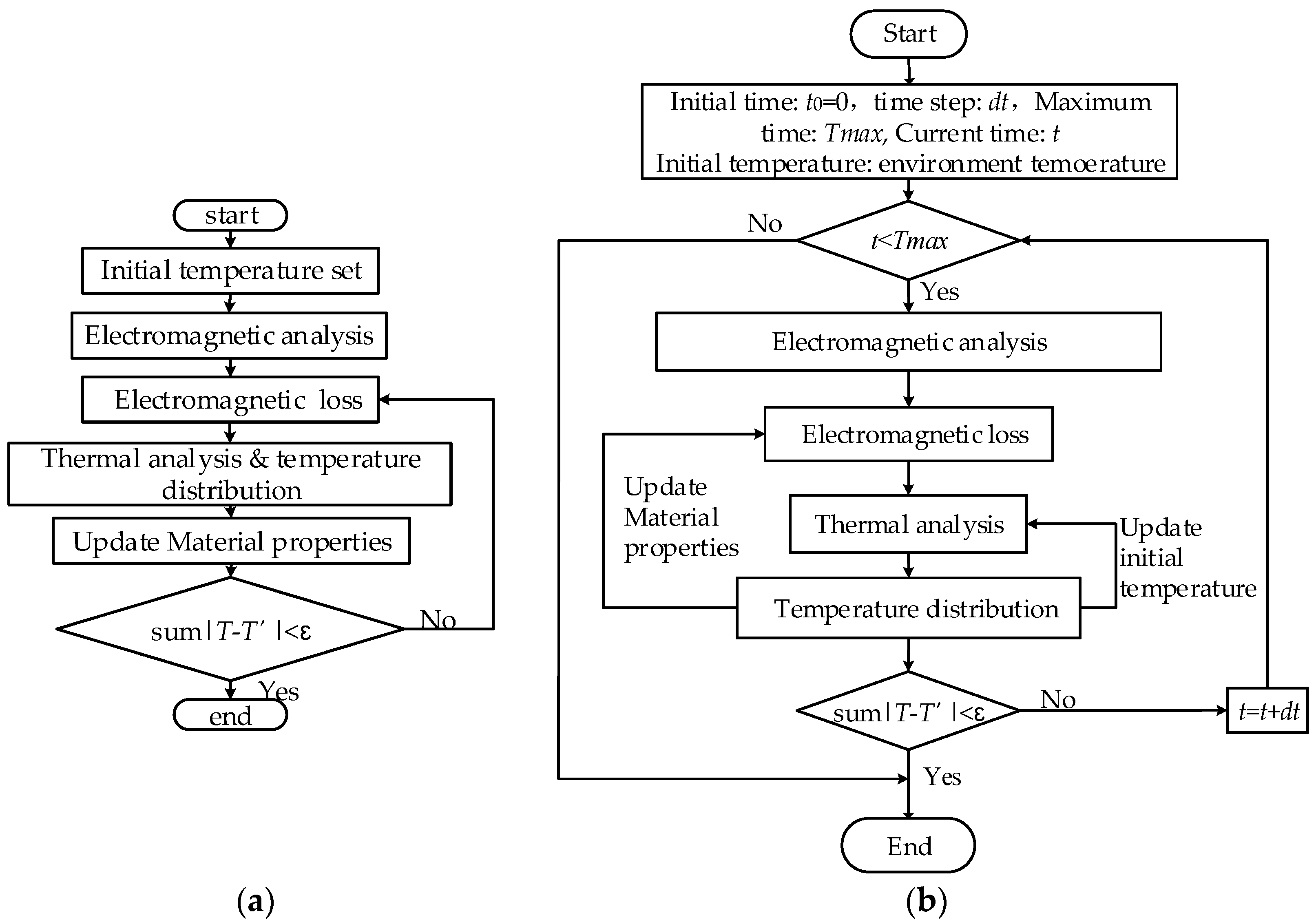
Since the time constants of the TH field and the EM field differs extremely, the bidirectional loosely-coupled solution method is adopted, that is, the EM field and the temperature field are calculated separately, and then the two fields are coupled through the data. For the analysis of TH field, steady state calculation and transient calculation are studied. The main advantages of steady-state calculation are that the number of iteration steps is small and the calculation is fast. However, the transient TH calculation is more suitable for transient analysis, such as the starting process of the motor, or during the operation of variable speed or variable torque. The calculation flow is shown in Figure 13.
The differences between the steady state and the transient state TH analysis are mainly as follows. (1) For the steady state TH analysis coupling model, there is only one iterative condition. In each iteration, the steady temperature distribution is obtained under the current conditions. Until the resulting temperature converges, the calculation stops. (2) For the transient TH analysis coupling model, there are two cyclic conditions. The outer cycle is about the time. When the computation time reaches the given maximum time, the computation stops. The inner cycle condition is whether the temperature converges or not. For each inner loop, the initial temperature values of the EM field and the TH field need to be updated from the result values of the previous inner loop. The value of dt in Figure 13b changes with the value of |T-T’|. If |T-T’| value is large, dt is small. If the |T-T’| value is small, dt is large.

4. Results Verification

In this section, the ac current of 3.6 A/mm2 is applied to the 12/10 FSPM machine. Although there is a water channel, the air nature cooling is adopted in this paper.
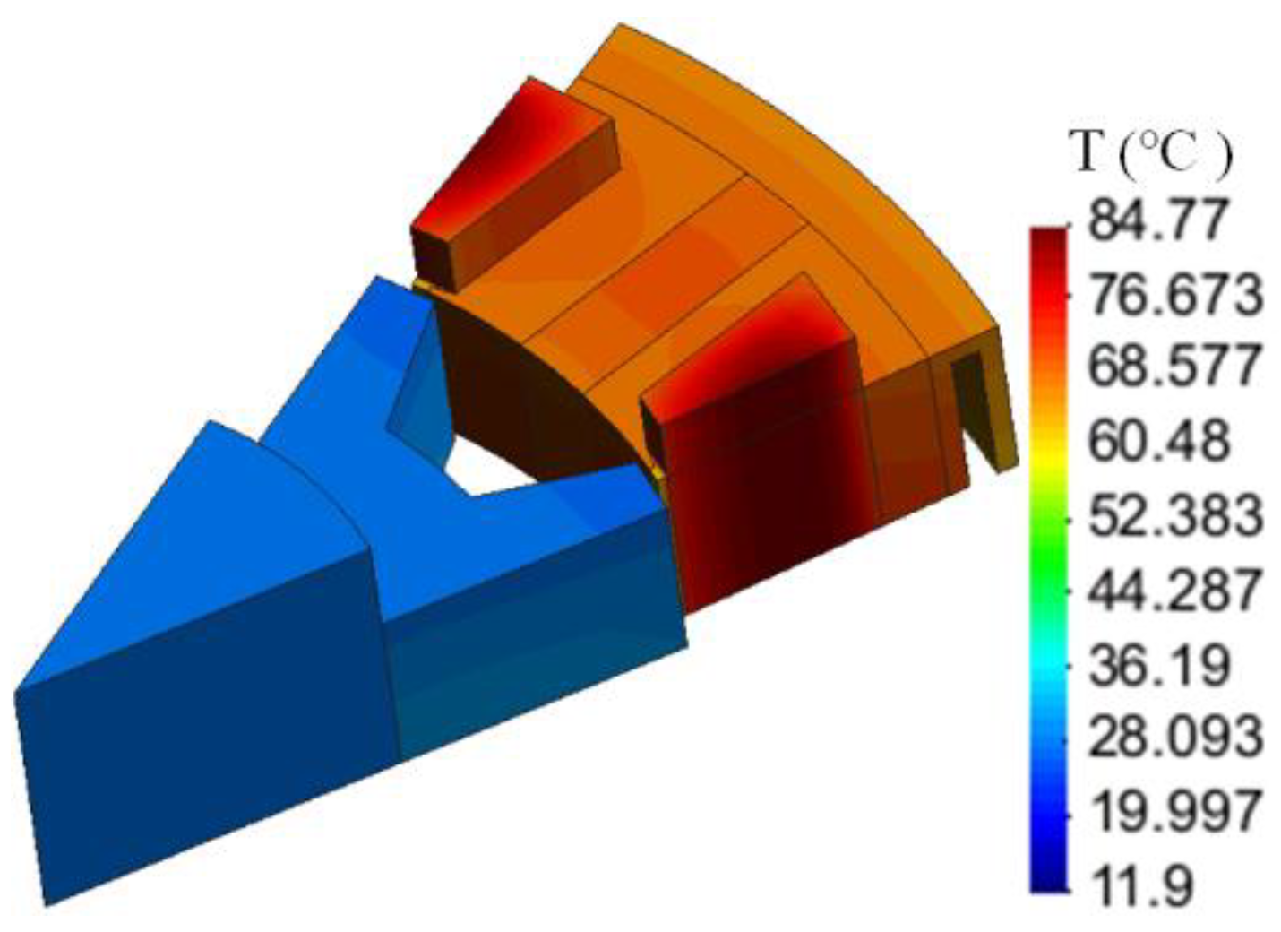
For the steady state TH coupling model, the EM losses and TH results are calculated as shown in Figure 14 and Table 2. The top temperature obtained by the steady state model is 84.77 °C, which is in the middle of the windings. For the steady state temperature field coupling analysis, five iterations are carried out with a total time of 34 min, and the average error of the final temperature was 0.1 °C.
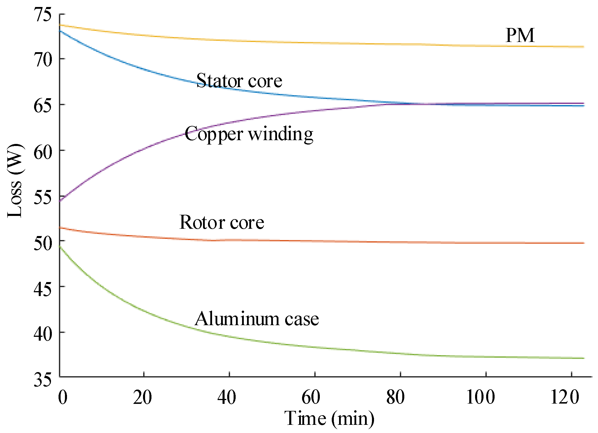
The calculated EM losses of different components of the machine is shown in Figure 15 by using the bidirectional coupling analysis model proposed in this paper. The copper loss increases by 20.7% because the effective value of the current remains unchanged while the resistance of the windings increases when the temperature increases. The core loss decreases when the temperature increases, which is consistent with the measured core loss by Epstein frame in section II. The stator core loss decreases by 11.36%, while the rotor core loss decreases by 3.4%. However, the resistivity of PM increases as the temperature rises. Besides, the eddy current induced inside the PMs is inversely proportional to the resistivity, while the PMs’ loss is the product of the square of the eddy current and the resistance. Therefore, the loss induced in PMs is inversely proportional to the resistivity. So the loss in the PM decreases as the temperature rises, as does the loss in the aluminum housing. From Figure 15, it can be seen that the loss deduced in the PM decreases by 3.02%, and the loss in the aluminum housing decreases by 24.7%.
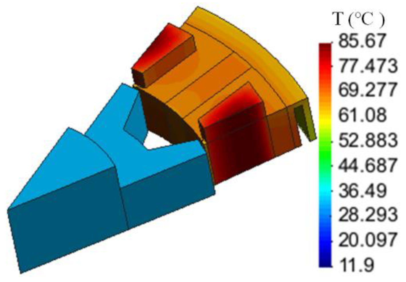
Figure 16 shows the results of temperature distribution in FSPM machine calculated by the transient TH coupling model. The top temperature is 85.67 °C, which occurred in the middle of the windings. For the transient temperature field coupling analysis, it takes a total time of 78 min.
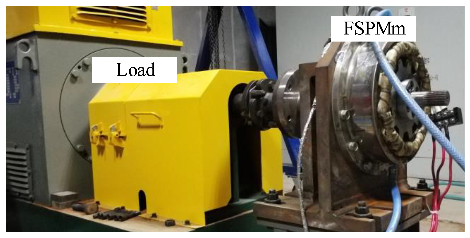
To validate the temperature obtained by the simulation, the TH rise experiment is conducted for the FSPM prototype machine. The FSPM machine is in the motor mode controlled by the DSP on the hybrid platform, as shown in Figure 17. In order to sample the temperature of winding accurately, three thermocouples are insert in the middle of the windings and the average temperature is considered as the temperature of the windings. In addition, three thermocouples are placed on the surface of stator core, PM, and aluminum housing. It takes two hours for the temperature to achieve stability. Table 3 gives the temperature results obtained by the simulation and experiment. The maximum error occurs in the windings, and the winding temperature result of transient coupling calculation is 3.73 °C higher than the experimental value, while the steady-state result is 2.83 °C higher than the experimental value.

5. Conclusions

This paper proposes a fast and accurate bidirectional coupling model based on the 2D EM field and 3D asymmetric minimum TH field, which reduces the calculation burden and realize fast calculation. In this method, the adaptive adjustment calculation step is used, which significantly reduces the calculation time. The core loss model considering the effect of the dc magnetic bias and at different temperatures is built. The eddy current loss and hysteresis loss in the silicon steel sheet decrease with the increase of temperature. In addition, when the FSPM machine is applied with the constant effective value of the current source and rated rotation speed, the copper loss rises when the temperature increases, while the losses induced in PMs and aluminum housing decrease. The maximum values of the temperature calculated by both the bidirectional coupling model and the experiment occurs in the middle of the windings. This method is applicable to all kinds of electrical machines. In the future, the influence of the PM’s partial demagnetization on the TH analysis based on the bidirectional coupling model between the EM field and TH field for the FSPM machine will be researched.

Author Contributions

J.W. conceived the idea of this paper and performed the simulations and also experiments, wrote the paper. B.L. helped to finish the experiments. Y.H., M.C., and B.C. provided guidance and revised the manuscript and add their thinking to validate the idea. All authors have equally contributed to the analysis and discussions. All authors have read and agreed to the published version of the manuscript.

Funding

This work was supported in part by the National Nature Science Foundation of China under Major Project 51991380 and the State Key Laboratory of Air-Conditioning Equipment and System Energy Conservation under Project ACSKL2018KT08.

Conflicts of Interest

The authors declare no conflict of interest.

References

  1. Cheng, M.; Hua, W.; Zhang, J.; Zhao, W. Overview of stator-permanent magnet brushless machines. IEEE Trans. Ind. Electron. 2011, 58, 5087–5101. [Google Scholar] [CrossRef]
  2. Cheng, M.; Zhu, Y. The state of the art of wind energy conversion systems and technologies: A review. Energy Convers Manag. 2014, 88, 332–347. [Google Scholar] [CrossRef]
  3. Hua, W.; Zhang, G.; Cheng, M. Investigation and design of a high-power flux-switching permanent magnet machine for hybrid electric vehicles. IEEE Trans. Magn. 2015, 51. [Google Scholar] [CrossRef]
  4. Cheng, M.; Sun, L.; Buja, G.; Song, L. Advanced Electrical Machines and Machine-Based Systems for Electric and Hybrid Vehicles. Energies 2015, 8, 9541–9564. [Google Scholar] [CrossRef] [Green Version]
  5. Vong, P.; Rodger, D. Coupled electromagnetic-thermal modeling of electrical machines. IEEE Trans. Magn. 2003, 39, 1614–1617. [Google Scholar] [CrossRef]
  6. Alberti, L.; Bianchi, N. A coupled thermal-electromagnetic analysis for a rapid and accurate prediction of IM performance. IEEE Trans. Ind. Electron. 2008, 55, 3575–3582. [Google Scholar] [CrossRef]
  7. Marignetti, F.; Colli, V.D.; Coia, Y. Design of axial flux PM synchronous machines through 3-D coupled electromagnetic thermal and fluid-dynamical finite-element analysis. IEEE Trans. Ind. Electron. 2008, 55, 3591–3601. [Google Scholar] [CrossRef]
  8. Sun, X.; Zhu, S.; Cheng, M.; Zhang, J. Coupled electromagnetic-thermal-mechanical analysis for accurate prediction of dual-mechanical-port machine performance. IEEE Trans. Ind. Appl. 2012, 48, 2240–2248. [Google Scholar] [CrossRef]
  9. Jiang, W.; Jahns, T.M. Coupled electromagnetic–thermal analysis of electric machines including transient operation based on finite-element techniques. IEEE Trans. Ind. Appl. 2014, 51, 1880–1889. [Google Scholar] [CrossRef]
  10. Mo, L.; Zhu, X.; Zhang, T.; Quan, L.; Wang, Y.; Huang, J. Temperature rise calculation of a flux-switching permanent-magnet double-rotor machine using electromagnetic-thermal coupling analysis. IEEE Trans. Magn. 2017, 54, 1–4. [Google Scholar] [CrossRef]
  11. Hu, Y.; Wang, J.; Li, B.; Chen, B.; Cheng, M.; Fan, Y.; Hua, W.; Wang, Q. Bidirectional coupling calculation of electromagnetic field and thermal field for FSPM machine. In Proceedings of the 2020 IEEE International Conference on Industrial Technology (ICIT), Buenos Aires, Argentina, 26–28 February 2020; pp. 139–144. [Google Scholar]
  12. Zhu, Z.Q.; Xue, S.; Chu, W.; Feng, J.; Guo, S.; Chen, Z.; Peng, J. Evaluation of iron loss models in electrical machines. IEEE Trans. Ind. Appl. 2018, 55, 1461–1472. [Google Scholar] [CrossRef]
  13. Zhu, S.; Cheng, M.; Dong, J.; Du, J. Core loss analysis and calculation of stator permanent-magnet machine considering DC-biased magnetic induction. IEEE Trans. Ind. Electron. 2014, 61, 5203–5212. [Google Scholar] [CrossRef]
  14. Cheng, M.; Wang, J.; Zhu, S.; Wang, W. Loss calculation and thermal analysis for nine-phase flux switching permanent magnet machine. IEEE Trans. Energy Convers. 2018, 33, 2133–2142. [Google Scholar] [CrossRef]
  15. Cai, X.; Cheng, M.; Zhu, S.; Zhang, J. Thermal modeling of flux-switching permanent-magnet machines considering anisotropic conductivity and thermal contact resistance. IEEE Trans. Ind. Electron. 2016, 63, 3355–3365. [Google Scholar] [CrossRef]
  16. Xue, S.; Feng, J.; Guo, S.; Chen, Z.; Peng, J.; Chu, W.Q.; Huang, L.R.; Zhu, Z.Q. Iron loss model under DC bias flux density considering temperature influence. IEEE Trans. Magn. 2017, 53. [Google Scholar] [CrossRef]
  17. Zhu, S.; Cheng, M.; Hua, W.; Cai, X.; Tong, M. Finite element analysis of flux-switching PM machine considering oversaturation and irreversible demagnetization. IEEE Trans. Magn. 2015, 51. [Google Scholar] [CrossRef]
  18. Wang, J.; Ming, C.; Li, B. An accurate and fast pm eddy current loss calculation method for flux switching permanent magnet machine. In Proceedings of the 2018 IEEE Student Conference on Electric Machines and Systems, Huzhou, China, 14–16 December 2018; pp. 1–6. [Google Scholar]
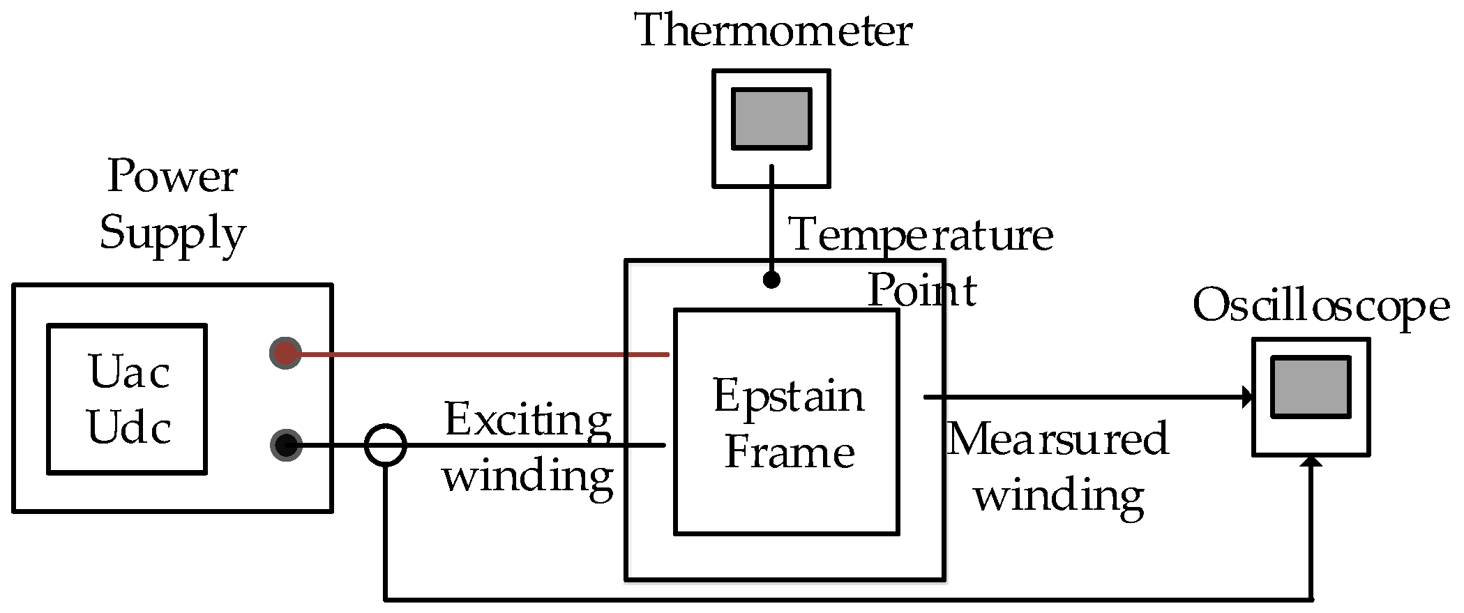
Figure 1. Epstein test apparatus.
Energies 13 03079 g001
Figure 2. Measured core loss in the Epstein frame at different frequencies, flux densities, and temperatures.
Energies 13 03079 g002
Figure 3. Loss coefficients Ke and Kh obtained by the experiments. (a) Eddy current loss coefficient Ke. (b) Hysteresis loss coefficient Kh.
Energies 13 03079 g003
Figure 4. Core loss considering the dc magnetic bias.
Energies 13 03079 g004
Figure 5. Core loss considering the dc magnetic bias.
Energies 13 03079 g005
Figure 6. The relation of experiment results and fitting curves.
Energies 13 03079 g006
Figure 7. B–H curves under different temperatures.
Energies 13 03079 g007
Figure 8. Extrapolation of B–H curve.
Energies 13 03079 g008
Figure 9. Prototype of 12/10 flux switching permanent magnet (FSPM) machine. (a) Sectional view. (b) Local diagram.
Energies 13 03079 g009
Figure 10. Assembling diagram of 12/10 FSPM machine. (a) Prototype. (b) 3D model.
Energies 13 03079 g010
Figure 11. Electromagnetic (EM) field analysis model.
Energies 13 03079 g011
Figure 12. Asymmetric minimum element thermal (TH) field.
Energies 13 03079 g012
Figure 13. Bidirectional coupling of EM field and TH field. (a) Steady state TH analysis. (b) Transient state TH analysis.
Energies 13 03079 g013
Figure 14. Temperature distribution obtained the steady state TH coupling model.
Energies 13 03079 g014
Figure 15. Results of EM losses.
Energies 13 03079 g015
Figure 16. Temperature distribution of FSPM machine.
Energies 13 03079 g016
Figure 17. Experiment platform.
Energies 13 03079 g017
Table 1. Main dimensions and performance parameters of the flux switching permanent magnet (FSPM) machine.
Parameters.UnitData
Outer radius of aluminum housing, RAlomm140
Outer radius of stator core, Rsomm130
Inner radius of stator core, Rsimm90.1
Width of stator core, θst°9.75
Length of pole shoe, lpsmm0.8
Angle of pole shoe, θps°115
Length of air gap, δmm0.9
Radial length of PM, lPMmm39.1
Circumferential length of PM, wPMmm11.9
Outer diameter of rotor yoke, Rrymm90.1
Inner diameter of rotor, Rrimm50
Width of rotor tooth, θrt°11.25
Degree of rotor yoke, θry°13.5
Axial length, Lmm55
Rated speed, nrrpm1000
Rated torque, TeNm107
Number of turns, N-12
Resistance of one phase, RsΩ0.03
Table 2. EM Losses Obtained by the Steady State Analysis (W).
Num.CopperPMHousingStatorRotor
ita.154.0273.7651.7273.7451.82
ita.267.0971.3438.3470.9850.05
ita.368.41671.1537.5470.9850.05
ita.468.5771.1237.4570.9850.05
ita.568.5971.1237.4470.9850.05
Table 3. Temperature Results (°C).
ModelsWindingPMHousingStator
Steady84.7770.2864.270.17
Transient85.6769.1761.1968.83
Experiment81.9468.0360.3468.55