1. Introduction
Geothermal systems that use ground-coupled heat exchangers (GHEs) and ground source heat pumps (GSHPs) are popular all over the world as a measure for energy saving for heating and cooling purposes. This is mainly true in the case of cold climates, even if the use of GSHPs has been extended to temperate climate conditions too.
One of the elements of uncertainty in the design and sizing of geothermal heat pump (GHP) systems is understanding the heat transfer with the ground and the related thermal properties. Different types of heat exchangers can be used, both vertically and horizontally installed. The most common vertical type is the borehole heat exchanger (BHE). Typical BHEs are about 100 or more meters deep and have a diameter of about 100 mm. The number of boreholes connected to the installed heat pump can vary from one for a residential building to several dozen in case of commercial or large-size buildings. In the case of horizontal applications, the heat exchanger is represented by pipe-coils buried 1.5–3 m below ground level.
A GHE’s performance depends on the ground thermal parameters (thermal conductivity and specific heat capacity) and the so-called borehole thermal resistance. An accurate evaluation of those parameters is fundamental for correct sizing of the ground-coupled apparatus and requires a preliminary experimental analysis.
Soil is a multiphase material composed of solid particles, water, and air. Each of the components has different thermal properties such that the effective thermal properties depend on the relative proportion of each component. Typical values of thermal properties of soil materials stand in the range of 0.25–8 W/m·K concerning the thermal conductivity
, 1500–3000 kg/m
3 for the density
, and between 0.7 and 2.0 kJ/kg·K for the specific heat capacity
. The resulting thermal diffusivity
that is a function of the previously defined thermophysical properties stands in the range between 10
−7 m
2/s and 4 × 10
−6 m
2/s [
1].
A thermal response test (TRT) is the typical method used to determine the thermal properties of the ground; this is particularly important for the design of ground-coupled heat pump (GCHP) systems, and in particular, for defining the heat that can be “extracted” from the ground. The conventional methodology, which involves both heat extraction and heat injection, can be useful for evaluating the effective value of ground thermal conductivity, the value of the borehole thermal resistance, and the undisturbed ground temperature. Because these values can be considered crucial for the design of a borehole heat exchanger (BHE), a high level of accuracy is required. For this reason, a diffused literature about TRT is available, where different reviews have been published containing the different methods and apparatus developed and analyzed for in situ tests. A comprehensive analysis of TRT methods can be found, for example, in References [
2,
3].
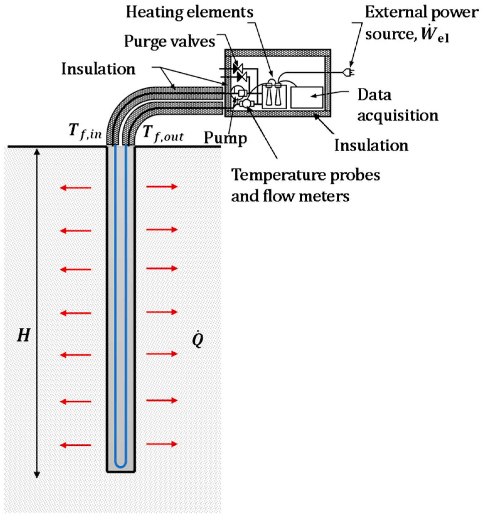
The conventional version of TRT is based on the injection of heat through hot water circulation into a loop buried in the ground, which produces an apparatus that is very similar (or the same) to the final BHE (see
Figure 1). In particular, water temperature variations are measured at the ground heat exchanger inlet and outlet sections during the test, along with the flow rate.
The measured temperature and flow rates are then analyzed with analytical or numerical models. The conventional TRT apparatus is not particularly expensive but the results obtained are often subject to relevant errors [
4,
5]. Moreover, the test duration is generally long (a minimum of 50 hours is required) and the perforation time and costs are not negligible. Therefore, the quite high cost and time consumption of a TRT remains an issue that prevents its widespread use [
6].
The considerations mentioned above permit us to clearly understand that research is still active. More precisely, the efforts of the researchers aim at:
Improving the spatial resolution of the thermal properties (of the ground) obtained. In this regard, different versions of the classical TRT have been developed, such as the distributed thermal response test (DTRT) [
7,
8,
9], enhanced thermal response test (eTRT) [
4], constant heating temperature method (CHTM) [
10,
11], and thermal response test while drilling (TRTWD) [
12].
Reducing the test duration. The version of TRT called TRTWD analyzed by Tuomas and Gustafsson [
12] and the CHTM method [
10] falls within this research area.
Simplifying the test apparatus and the test procedures; this has been tried with the version referred to as HC-TRT [
13] and the TRT with natural stimulation [
4].
Analyzing the results of the TRT and comparing different interpretation methods of the experimental results [
14,
15,
16] in a reduced time scale [
6,
17] and with reduced uncertainties [
18,
19,
20].
Following the last point, improvements do not only concern experimental analysis but also mathematical models. The common interpretation of the data is based on the use of numerical and analytical methods. Numerical models result in a more detailed description of the heat transfer process, accounting for 3D phenomena, arbitrary geometries, and boundary conditions [
21,
22].
Analytical models require several simplifying assumptions and refer to standard reference configurations. Generality and short computational times make analytical models preferable at the beginning of the design process, especially considering the typical lack of data at this stage [
22,
23,
24,
25,
26]. An accurate analysis of the various experimental methods and models for the analysis of the experimental data (see
Section 3) suggests that there is still a need for improvement in the TRT process and that further improvements could be obtained by combining the various proposals in the literature.
From the operators’ perspective, TRT is often considered too expensive and requires quite a long time (up to five days of experimental analysis). For this reason, TRT is not widespread and is generally avoided. The sizing of the ground heat exchangers is therefore based on the application of some empirical data and “rules of thumb”: the range considered is from 20 to 100 W for each meter of the borehole heat exchanger based on the qualitative composition of the soil strata [
27,
28].
However, this often determines an oversizing of the ground source heat exchanger, leading to unviable installation costs and inefficient operation of the heat pump. As a consequence of the market expansion, standardization and quality assurance of TRT have been recognized as fundamental such that the development of new and fast methods, as well as cost reduction, can be highly appreciated.
An idea for increasing the application of TRT for design purposes could be the connection of TRT with standard geotechnical investigations, which should be mandatory before the start of constructing a new building, in a lot of countries. For instance, in Italy, the in situ penetration test is mandatory to a minimum depth of 30 m below ground level or the piles base (when needed). According to the typical depth of foundations, the geotechnical investigation generally requires a bore depth of several tens of meters, namely a similar size to BHEs. A promising association of geotechnical and thermal tests is already available in the literature. For example, the thermal cone penetration test (TCT) developed by Akrouch et al. [
29] uses the heat generated by friction during the insertion of the cone to infer the thermal conductivity. Other techniques will be reviewed in the paper.
After a preliminary analysis of the recent evolutions of TRT, this study aimed at proposing a method for estimating the thermal properties of soil in a relatively short time and an economical manner, thanks to the conjunction with the geological test already needed for structural purposes. The thermal properties of soils can thus be estimated, together with other key geotechnical properties, such as consolidation and friction coefficients. The objective is also to understand which one of the available methodologies could be the best one for conjugating the two different tests.
2. Measuring Soil Thermal Properties with Experimental Analysis
The sizing of a GHE requires the knowledge of typical values of the thermophysical properties of soil. These properties can be evaluated using experimental in situ analysis, such as the TRT. A typical TRT allows for in situ measurements of the ground thermal properties. In the classical procedure, already mentioned in the previous section, the fluid circulating in a GHE is heated at a constant rate and the evolution of its temperature is monitored. The basic idea is that the fluid temperature rise is a function of the ground’s thermal conductivity of the borehole’s equivalent thermal resistance and of the linear heating power. Therefore, from the analysis of the temperature evolution of the fluid, the thermal properties of the ground can be indirectly evaluated using a heat transfer analysis of the system.
Heat transfer modeling between the fluid circulating in a BHE and the surrounding ground is a quite complex task because of the several phenomena involved. The presence of groundwater at a given level influences the moisture content of the ground, thus affecting its effective thermal conductivity. Furthermore, in the case of significant flow, convection has a greater influence than conduction. Several criteria have been proposed in the literature to find out the influence of convective heat transfer on the evaluation of thermal conductivity (see, for instance, Conti et al. [
30]). Another problem is that the ground is generally stratified such that the BHE exchanges heat with layers with different conductivities; this invalidates the assumption of constant linear heat flux, which is typical of conventional TRT. The aforementioned effects make it difficult to model the heat transfer in a borehole.
Classical TRT data interpretation employs analytical models and relies on simplified hypotheses: the ground is considered a purely conductive and homogeneous medium, the heat transfer is considered in a radial direction (solutions of one-dimensional Fourier equation), and the heat source is assumed to be uniform with a negligible radial extension. The infinite line source (ILS) model is typically used to analyze TRT data [
22]; other classical post-processing equations based on analytical models are reviewed in
Section 3. Numerical models can consider all the effects neglected by analytical models to better simulate the thermal behavior, such as ground stratification and the influence of groundwater. However, this is possible only if their characteristics were well-known before starting the test procedure and this is not the case in practice. In the end, whatever approach is adopted, conventional TRT gives the value of the effective ground thermal conductivity: it accounts for all the thermal phenomena occurring in the borehole and is strictly related to the depth investigated.
The development of in situ tests, such as TRT, is strictly connected with the perspective of the diffused use of GSHP systems. Regarding a design based on standard data and a “rule of thumb”, a design based on TRT produces a more accurate design with better performances during operation and lower installation costs are expected. On the other hand, TRT requires non-negligible costs and it is reasonable to think that in the current form, it can be recommended only for systems with a minimum thermal load of 50 kW [
27].
However, the economic suitability of GSHP is a delicate issue. The investment is high relative to traditional solutions, and thus annual savings should be high enough to ensure an acceptable payback time. Annual savings can be directly related to climatic conditions: it is evident that colder temperatures require greater energy consumption and entail proportionally greater savings. This means that the analysis of climatic conditions is essential for evaluating the convenience of a GSHP installation. Effective designing is an economically sensible process due to the high costs related to the type of ground heat exchangers, as well as the ground properties.
In general, it is possible to distinguish between two cases if experimental data related to the ground are available. If ground thermal properties are derived using a TRT, knowledge of the data accuracy is fundamental.
Slight underestimation or overestimation of the thermal conductivity value entails significant oversizing or under-sizing of the ground-coupled heat exchanger, with a relevant influence on the initial investment or operating costs. Sanner et al. [
31] estimated these effects for a 50 kW GSHP designed for a ground thermal conductivity equal to 2.2 W/m K. An uncertainty of about 0.4 W/m K (corresponding to 20%) would entail an important variation in the cost of the whole system. Borehole resistance also has a strong impact on the exchanger depth and related investment cost; oversizing could result in additional expenses [
26]. Based on such considerations, the maximum allowable error for ground thermal properties is 10%.
In the last thirty years, following the growing interest in GSHP systems, many methods for experimental characterization of the ground have been presented in the literature. Two main directions are considered: “quick and dirty” tests with a reduced accuracy that are to be employed in the routine design of small-capacity systems (e.g., residential houses), and the more sophisticated tests providing more accurate data for greater systems.
3. Thermal Response Test: Methodological Description and Theoretical Analysis
A TRT is based on the interpretation of the responses (i.e., the change in temperature of the circulating fluid at the wellhead) resulting from a thermal stimulation accomplished via the extraction or injection of a given heat flow.
The ground thermal parameters obtained from the test are the:
effective ground thermal conductivity
undisturbed ground temperature
thermal diffusivity of the ground α
borehole thermal resistance .
TRT data can be processed using analytical or numerical methods. Several authors have suggested different experimental procedures and models to improve the accuracy of TRT and to shorten the test time.
The first investigations to determine in situ values of ground thermal conductivity and thermal resistance in BHE systems were carried out by Mogensen in the 1980s [
32]. The results of relevant activities are provided in Eklöf and Ghelin [
33] and Austin [
34]. Conventional thermal response tests, currently done on a commercial basis, rely upon these schemes (see
Figure 1 and
Figure 2).
A heat exchanger is installed in the ground (it will be part of the final installation) and connected to the test rig, which mainly contains a heating and/or chilling device and a circulation pump; linking piping has to be insulated and shielded. The loop is then filled with water or a mixture of water and anti-freezing fluid throughout the rig. Measurements are taken by thermometers installed at the borehole wellhead.
In the first phase of the test, the fluid is circulated without heat injection or extraction to determine the undisturbed ground temperature. The correct duration of this part of the test was discussed by Gehlin and Nordell [
35]. In the second phase, the electrical resistance or the chiller is switched on and the fluid starts exchanging heat with the ground. The thermal response of the ground is taken as the arithmetic mean of the measured inlet and outlet temperatures; experimental data are finally used in a heat transfer model to estimate the ground’s thermal conductivity and borehole resistance. The cost of the test is closely connected to the penetration depth and the long time required, which depends on the time for the thermal perturbation to reach the undisturbed ground and a steady heat flux condition at the borehole wall. The test period usually advised in the literature is about 50 hours for obtaining an error in the thermal conductivity that is below 10%, as it can be observed in
Figure 3, where the evaluation of the thermal conductivity using TRT is reported for two different ground typologies.
Moreover, the results of the test are sensitive to the depth of the borehole. The heat transfer between the fluid circulating in a BHE and the ground is quite complex due to the different phenomena involved:
The presence of groundwater flow means that convection has a greater influence than conduction, while the groundwater level influences the moisture content of the ground, thus affecting its conductivity. Several criteria have been proposed for considering this [
21,
30,
36].
The ground is generally stratified such that the BHE exchanges heat with layers with different thermal conductivities.
The heat is mainly transferred in the radial direction; in addition to that, effects such as the geothermal gradient, finite length of the exchanger, and thermal short circuit entail an axial heat flux.
Analytical models rely on simplified hypotheses: the ground is considered to be purely conductive and homogeneous, and the heat transfer is taken as being radial (solutions of the 1D Fourier equation). Numerical models can consider these effects when simulating the thermal behavior; however, when treating experimental data, it would be possible to consider stratification and groundwater influences only if their characteristics were well known, which is not the case in practice.
4. Mathematical Models for TRT Data Analysis
Analytical models used to compute conductive heat transfer during a TRT are based on solutions of the Fourier equation; they assume the ground is a homogeneous and isotropic medium. The classical model adopted is the one-dimensional ILS model, which neglects axial effects. The solution of the conductive problem provides the so-called
g-function (introduced in [
37]), which is reported in Carslaw and Jeager [
38]. The temperature of the ground at the borehole wall and that of the undisturbed ground are related to
according to:
The thermal response of the fluid (i.e., the average temperature
) is then related to the borehole wall temperature via the thermal resistance
, which involves accounting for the heat transfer phenomena inside the borehole (pipes and grouting, as long as the hypothesis of steady-flux conduction inside the borehole is valid). Finally, the two conductive problems can be unified such that:
As mentioned above, the simplest and more used analytical
g-function, namely
, for the analysis of TRT results is the ILS model [
38]. In this case, the ground is taken to be an infinite medium and the exchanger is an ILS with constant linear power. The ILS model gives the radial temperature distribution as a function of time: for times longer than
(a few hours for a typical BHE radii and ground thermal properties), the borehole wall temperature is given by:
Equation (3) allows for an immediate evaluation of the ground thermal conductivity since there is a direct proportionality between the thermal evolution of the fluid
and the time
(see
Figure 4). On a semi-log plot, the long-term evolution of
, or the temperature difference
,
f, appears as a straight line. The slope of the line
can be evaluated through a simple linear regression of the later points. Then, the value of
is determined. Once that property is known, the borehole resistance
or the thermal diffusivity
can be calculated using Equation (3).
The line source method is commonly proposed in the literature for the measurement of the thermal conductivity and thermal diffusivity of fluid and solid materials; a possible application is described by Franco [
39].
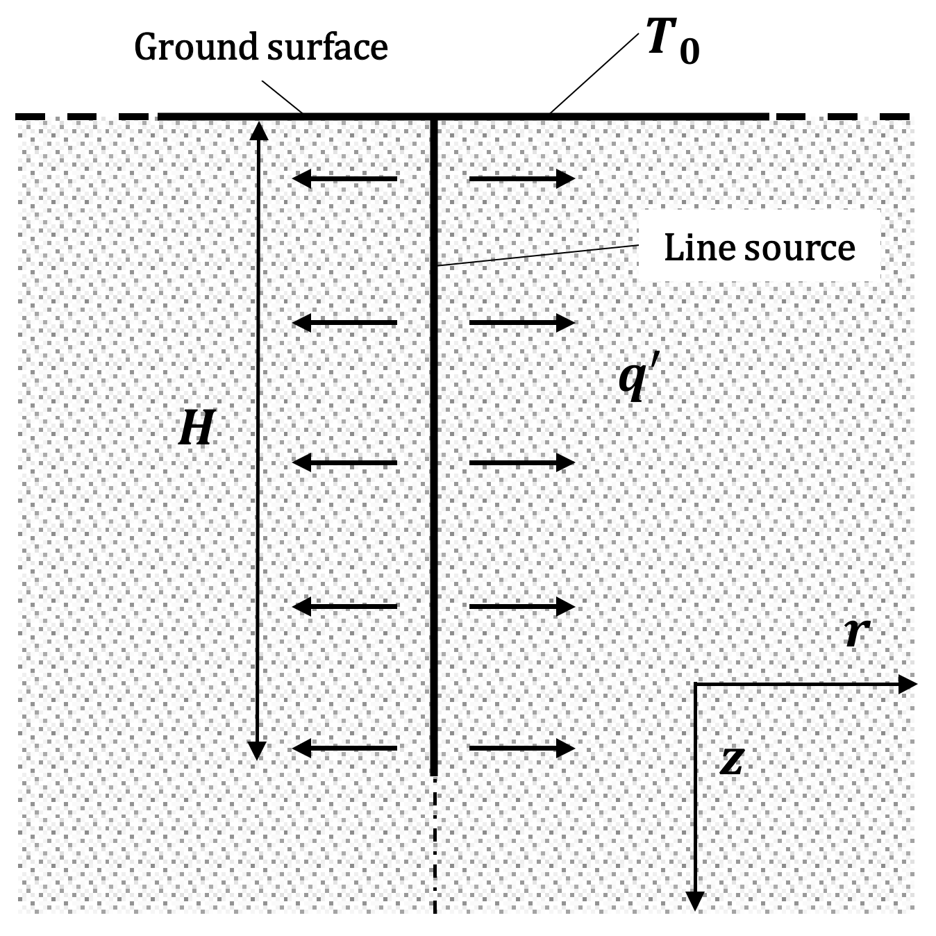
The finite line source (FLS) model is another suitable model for the interpretation of TRT data. The Fourier equation is solved for an axial-symmetric semi-infinite solid (see
Figure 5) under the following assumptions:
The solution of the just-discussed conductive problem can be expressed in the dimensionless form of Equation (1) by defining an alternative
g-function to the one related to the ILS model. One of the most well-known expressions of the FLS
g-function is proposed by Eskilson and Claesson [
37]:
The
g-function for this model can be solved numerically but the data are available in a tabular form too. However, to analyze the results of TRT, it is desirable to have a handier expression to be used in the design procedures. Zeng et al. [
23] proposed a new form of the FLS
g-function based on the integral mean of the borehole wall temperature. However, the proposed formulation is not easily solved, but it has been considered in Lamarche and Beauchamp [
40]. The expression proposed in Claesson and Javed [
41] extends the generality of the FLS model by considering an arbitrary position and extension of the line heat source along the z-coordinate, namely
. In this case, the
g-function expression reads:
where:
In a different analysis, Bandos et al. [
25] focused on vertical effects by considering the geothermal gradient and the variation of the surface temperature on the Fourier equation’s solution. Other common models are the infinite and the finite cylinder source models that differ from the line source for the shape of the heat source, even if the results are not appreciably different when the aspect ratio of the heat source is quite high. Moreover, despite their higher precision in describing the physical system, the high computational cost does not encourage the use of cylindrical models (as discussed in Lamarche and Beauchamp [
40]).
The use of numerical models can be another choice for the analysis of experimental data. There are several kinds of 1D, 2D, and 3D models in the literature; they provide a better description of the system and investigate axial effects but their full potentialities can only be exploited in direct problems: for example, they can manage power variations but these are due to external interactions and/or electrical fluctuations; therefore, they are neither predictable nor assessable [
21].
5. Thermal Response Test: Analysis of Recent Innovative Concepts
The conventional TRT version analyzed in the previous section is quite a simple method for ground thermal characterization, even if it presents some serious weak points. Some innovation in the matter appears to be quite interesting. In the following pages, different versions of the TRT are analyzed and reviewed to identify which one is more promising for possible employment in standard in situ tests.
5.1. Thermal Response Test while Drilling (TRTWD)
TRTWD is a particularly interesting method for the execution of thermal response tests based on the utilization of information obtainable via the drilling fluid of the borehole, even if it uses the same basic principle as the standard TRT measurement. The method has been discussed by Tuomas and Gustafsson [
42]. The head of the hammer perforating the ground dissipates energy, which is partly transferred to the string fluid and partly to the ground. The working principle involves measuring the inlet and outlet drilling fluid temperature to determine the thermal conductivity profile in the ground. Data are analyzed using a numerical code, where the analysis is based on energy conservation equations. A major advantage compared to standard TRT is that this method gives a “continuous value” of the thermal conductivity along the borehole instead of an integral-mean value. The disadvantage is that the borehole resistance is not evaluated but a standard value must be used for the given configuration.
5.2. Enhanced Thermal Response Test (eTRT)
This is a technique that has been industrially developed. It is possible to find some details about the method in Poppei and coworkers [
4,
43]. A small wireless submergible probe called NIMO-T can be lowered into boreholes to measure pressure and temperature profiles. The undisturbed ground temperature profile, known together with the axial heat flux, allows for finding the thermal conductivity. This cannot be done directly because the axial heat flux is variable due to local phenomena (geothermal anomalies, shallow fluctuations induced by variation of the superficial temperature, etc.). For this reason, the NIMO-T probe is used in association with a conventional TRT: the probe is used to measure temperature profiles before the test, just after its execution, and one or two days later. An appropriate numerical model simulates the thermal responses and matches them with the measured ones by varying the ground properties. Diagnostic plots are techniques typical of hydrogeological investigations transferred to the thermal applications according to the mathematical similarity between the Darcy and Fourier equations.
The method appears to be completely different from the conventional one; while the conventional one tends to minimize the external interference on the fluid, this method eliminates the insulation of the external piping and every device for thermal supply, where fluid exchanges heat with the ground and the external air (that acts as the heat source/sink). The variables measured are the mass flow rate (considered to be a constant) and the inlet and outlet temperatures of the fluid. The interpretation of data is based on the convective–conductive analytical model described in Equation (8):
where:
By using Equation (8), it is possible to evaluate the return temperature of the fluid
after the time of a complete circulation
to the depth
and back to the surface. Since the flow and borehole characteristics are known,
is the only unknown variable that can be evaluated through the best fitting of test results. The ground’s thermal conductivity can thus be calculated through Equation (9). Further details on the model are available in Poppei et al. [
4].
5.3. Distributed Thermal Response Test (DTRT)
The DTRT is a conventional thermal response test in which the fluid temperature is not measured at the borehole head but rather along the entire exchanger using an optical fiber cable (utilizing the Raman effect). Measurements are not continuous; they are taken at certain depths and at different time resolutions, both during the test execution and the thermal recovery phase. Data can then be analyzed by an infinite line source, as discussed by Acuña et al. [
7], or by using the approximation of an infinite cylinder source, as proposed by Fujii et al. [
8]. This technique allows for obtaining a vertical profile of the ground conductivity, and when an infinite line source is used, of the borehole resistance.
5.4. Constant Heating Temperature Method (CHTM)
The version of the method called CHTM utilizes a rig similar to those used for normal tests, with the possibility to choose between heat injection and extraction. The temperature of the inlet fluid is defined and controlled by regulating the chilling or heating devices. The main elements of the method can be found in Wang et al. [
10]. The main idea is that the direct proportionality between the mean fluid temperature
and the linear power exchanged in steady-state conditions
is:
The borehole temperature
can be calculated using:
The thermal conductivity
can be obtained using Equation (11) through the FLS
g-function (see Equation (5)):
5.5. Thermal Response Test Using Heating Cables (HC-TRT)
This particular version of the method has been proposed by Raymond et al. [
13]. In this case, thermal power is transferred to the fluid inside the borehole via electrical heating cables. The fluid is still in the exchanger and temperatures are measured along the vertical profile. There are two phases: in the first one, with a duration of about 50 hours, power is dissipated, while in the second one, lasting about 50 hours, the ground is left in thermal recovery. The temperatures used for the thermal characterization of the ground are those measured in the recovery phase, which can be analyzed theoretically using the ILS model (see Equation (13)) or through numerical analysis.
The idea of using the recovery period as it is considered more accurate has also been discussed in different papers, such as Signorella et al. [
21] and Kurevija et al. [
44]. From the analysis of Signorelli et al. [
21], it appears that a length of 30 m and a time of 30 hours could be a good compromise between accuracy, duration, and simplicity of the test.
5.6. Thermal Cone Dissipation Test (TCT)
Akrouch et al. [
29] proposed a new test called the thermal cone dissipation test (TCT). The authors intended for this to be considered an in situ technique that is used to determine the thermal properties of soils. The proposed technique expands upon the capabilities of the well-known geotechnical method known as the cone penetration test (CPT).
The apparatus consists of a cone penetrometer equipped with thermocouples located behind the cone point. For the measurement, the same apparatus is pushed into the ground at a constant rate of 2 cm/s. The friction between the cone and the soil increases the cone’s temperature. After that, the temperature decrease is evaluated as a function of time. The duration is approximately 30 min. The data acquired during the penetration are used to estimate the thermal conductivity and other thermal properties of the soil. The advantage of the TCT relative to other tests is that it does not require an additional heater to induce the thermal perturbation in the ground. The heat caused by the friction between the cone and soil during the penetration is considered sufficient to induce the thermal perturbation in the ground. The idea developed by the author is interesting, even if the power generated during the penetration strongly depends on the type of soil.
5.7. Discussion
Considering the various methods tested for ground thermal characterization, the TRTWD appears to be a very interesting one since it would result in a vertical profile of the thermal conductivity and a lower cost of the test. It only requires measurements during borehole drilling. The borehole resistance cannot be assessed using this method but it could be evaluated using empirical formulas. However, the practical application of this technique is not easy: the solution of the direct problem shows that temperature changes of the string fluid with soil with different conductivities are extremely small; the execution of the TRTWD would require quite high precision temperature measurement [
42]. Moreover, there would be operational problems: instruments could be disturbed by dust and vibrations generated by the ongoing perforation.
The idea of TRTWD has not been developed much in the last few years but it presents various advantages relative to a conventional TRT: the rig is very simple; moreover, the mathematical model directly refers to the mean temperature between the inlet and outlet, and due to its simplicity, permits fast analysis of the data. Negative aspects of this method are the fact that the ground temperature profile is approximated as being linear without considering the impact of external conditions on the shallow zone; another problem is the small temperature differences between the fluid and the ground, which can induce relevant errors in the evaluation of ground thermal properties.
Considering the other methods, it is possible to understand that the CHTM method has more drawbacks than advantages: this method allows for shortening the test length and eventually requires more time than a conventional TRT, with even less complete results. While Wang et al. [
10] underline the faster approach of the steady-state CHTM versus a traditional TRT, they just pass over the fact that four executions of the test are needed, which means a longer duration, even without considering the dead time for the thermal recovery of the ground between one test and another. Furthermore, borehole resistance is required as input data.
The other three methods analyzed appear to be more promising from the perspective of the future development of TRT tests.
The eTRT seems to be a good method that gives a vertical profile of conductivity. Nevertheless, considering the analysis by Poppei et al. [
4], the validity of the numerical interpretation of data is unclear. A good agreement has been shown when evaluating a single layer only but it has not been demonstrated whether the conductivities of the different regions are correlated; it is important to have very clear data regarding the conductivity profile, otherwise, results would have the same usefulness as a mean value. Diagnostic plots are a truly effective new concept in the interpretation of TRT data: their strength is not found in the conductivity given but rather in the monitoring of the test progress, which allows for the optimization of the test duration and economic savings. The required calculations are not complex; therefore, their application is advised for whatever kind of TRT is performed.
The version of the TRT called a DTRT appears to be promising: the future perspective of TRT is sure to have a vertical profile of conductivity and borehole resistance, at least for bigger installations; these enable the optimization of the design and constitute a further perspective for possible improvements. Regarding the interpretation of data, the infinite line source, as proposed by Acuña et al. [
7] seems to be better than the cylinder source model, which turns out to be a complex iterative procedure that does not even give the borehole resistance as a result. Nevertheless, some issues still must be assessed:
The minimum duration of such a test is not clear, as only experimental tests are present in the literature.
Optical fiber thermometers do not have a high sensitivity or accuracy; therefore, attention should be paid to the spatial resolution of measurements (a minimum of 10 meters is advised).
Since the length of the source is reduced, it could be interesting to investigate whether it is better to make use of a finite line source theory for the interpretation of the data.
Finally, the HC-TRT appears to be an innovative method in terms of both its test rig and the test execution; its advantages relative to a conventional TRT are:
The power exchanged between the fluid and the ground is more constant and uniform since heat is generated directly inside the borehole; this fits with the hypothesis of analytical models, resulting in a more accurate test.
The dimensions and weight of the rig are largely reduced.
Temperatures can be measured along the borehole depth to obtain a conductivity profile.
Notwithstanding this, HC-TRT presents some intrinsic weak points:
Concerning the developments of analytical models, it is clear that FLS methods cannot improve on TRT results simply because its duration does not allow for the appreciation of any difference between this model and the infinite length version. Nevertheless, it would be interesting to compare interpretations of the same data set with the two models to prove this experimentally. Moreover, the FLS model could be useful for the analysis of the long-term performance of GSHP and interactions among the boreholes of a huge installation.
Several alternative TRT methods aimed at preventing some drawbacks of the basic method are summarized in
Table 1, in which an attempt is made to provide the positive and negative aspects of each one.
6. Connection between TRT and Geological Tests: A Possible Path for Standardization and Widespread Use
As discussed in the previous sections, a relevant number of in situ tests have been proposed in the literature for determining soil thermal properties. Different aspects provide interesting elements in each one of the methods. In this section, we introduce new methods that try to join the positive aspects of the most interesting methods available in the literature.
Unfortunately, the use of TRT is not particularly widespread for preliminary tests, and the sizing of GSHP is often based on the use of some reference data available in the technical standards; this often produces an oversizing of the BHE and the GHE general.
Nowadays, TRT is carried out only for high-capacity installations with many expected BHEs. TRT results are used, together with the thermal loads required by the user facility, to calculate the total ground-coupled heat exchanger depth according to the classical relation given in the handbook by ASHRAE - American Society of Heating, Refrigerating and Air-Conditioning Engineers [
45]:
Considering this equation, the borehole resistance
is explicitly used while the ground conductivity is indirectly used to define the three thermal resistances
,
and
; in particular, these resistances are proportional to
[
46]. The design procedure is iterative: once the total depth
is known, the designer chooses how many exchangers to use, and based on this, re-determines the interference temperature
and verifies the total length once more, as discussed in Lamarche and Beauchamp [
40].
This project routine is incoherent with the use of the ground conductivity as given by a conventional TRT since it is an effective property of the ground strata and is strongly related to the depth of the tested borehole. Methods giving a single equivalent value of conductivity, such as classical TRT, limit the design flexibility since the length calculated using Equation (14) must be divided by several BHE of equal length to the one used for the TRT; otherwise, the effective thermal conductivity would be different. In this way, the actual design variables only produce the number of exchangers and their disposition in the field.
To optimize the design (in terms of the BHE number and depth), we propose to characterize the ground using vertical profiles of conductivity through a concept like a distributed thermal response test (DTRT) associated with line source evaluation. Moreover, it is advised to compare the results given with an infinite and a finite line source method to evaluate the impact of finite length effects; even if in the foregoing these seem to affect only the long term behavior of the borehole, according to Signorelli et al. [
21], these could also be detected in the short term. TRT is not usually done for smaller installations for economic reasons. The duration of the test cannot be significantly decreased as it has an intrinsic lower limit; it can be at most optimized using techniques such as diagnostic plots. GSHPs are usually made for new buildings as they work well with low-temperature heating systems. Considering that the major expense for a TRT is the borehole perforation, it is reasonable to think about integration between geotechnical and thermal analyses.
The execution of preliminary geotechnical tests is mandatory in earthquake-prone countries. The first step in assessing vulnerability is acquiring knowledge of the mechanical properties of the constituent materials. The current European seismic codes [
47,
48] require preliminary investigation, to understand the changes in soil properties that can occur over time [
49].
In Italy, for example, new buildings require prospecting for the assessment of geological and seismic properties of the ground; for example, in Italy D.M., 14 January 2008, the “Technical Norms for Constructions” requires an indication of the category of foundation soil. The definition of the foundation soil category requires the execution of in situ geotechnical tests, such as a standard penetration test (SPT), cone penetration test (CPT), seismic prospecting in a hole (down-hole or cross-hole), or other tests near the center of gravity of the building. The details of these methods are provided in Akrouch et al. [
29].
The idea here proposed in the paper is to install a testing exchanger in the borehole (with a length of 30 meters) and apply a heating cable thermal response test (HC-TRT) or a classical TRT with an auxiliary fluid using only the 30 m available; in this case, it is extremely important to optimize the parameters (diameter of the pipe, mass flow rate of the fluid, inlet temperature) to obtain a fast stabilization of the efficiency curve. HC-TRT has the advantage of a simple rig and testing procedure; this is important from the perspective of the transfer of all the duties to a single company, which is a geotechnical one. The conductivity given by such a test would be related to the limited depth of 30 m; since the number of BHEs to be installed is small, the approximation of constant conductivity with depth is valid, unless there is relevant groundwater flow deeper in the ground. On the other hand, from Signorelli et al. [
21] (see
Figure 3), it appears that at a length of 30 m and a duration of 30 h could be a good compromise between accuracy, duration, and simplicity of the test. In the next sections, two methods for analyzing the soil thermal properties that can be joined to the execution of mandatory geotechnical tests are proposed and discussed.
6.1. TRT in Conjunction with Geotechnical Tests
The proposed method is based on the ILS (or FLS) model and the classical
ε-NTU method for the heat exchanger analysis [
50]. The ground thermal conductivity can be estimated through measuring the inlet and outlet temperatures of the fluid circulating in the same borehole used for the geotechnical investigation without the need for another drilling. The heat transfer effectiveness is defined as:
Where NTU is the number of transfer units. According to the model of the ILS (see Equation (3)),
can be expressed as:
where
represent the bore depth required by law for the geotechnical test (
H ≥ 30 m),
is the time required for the experiment, and the borehole radius can be estimated based on the pipe’s radius using
. The relationship between the fluid temperatures
and
, NTU, the ground thermal conductivity
, and the borehole thermal resistance
becomes:
In this way, indirect estimation of the thermal conductivity can be obtained from the measurement of the fluid inlet and outlet temperatures and , respectively. The velocity of water should be maintained in the range between 0.5 and 1.3 m/s, while the inner and outer pipe diameter goes from 2.6 to 3.2 cm and 3.2 to 4.0 cm, respectively. In any case, a turbulent regime should be ensured within the duct.
Regarding the rig, it would be interesting to evaluate the feasibility of a version of the TRT such as an HC-TRT using fluid circulation instead of a heating cable. The addition of the device would result in the possibility of getting information about the borehole resistance.
Figure 6 shows a schematization of the system. Regarding the layout presented in Wilke et al. [
9], a circulation pump and an expansion vessel are necessary, and the loop should be closed using a thermally insulated and shielded pipe.
The measurement scheme would be the same, independent of the rig used. This layout aims toward the possibility of evaluating either a mean conductivity or the conductivity for two to three layers; two couples of thermal sensors (e.g., thermocouples or thermistors), located at 2, 5, 25, and 29 m of depth, allow for evaluating the conductivity profile. The choice of using thermocouples as thermal sensors is due to the tight spatial resolution of measurement points: the temperature difference between one and another will be small; therefore, sensible thermometers are required. The data can be analyzed using Equation (17). It is also possible to compare the results of the same set of data with those of the finite line source model to evaluate the accuracy of the ILS model. If the test is run with the circulation of fluid and only mean values are measured (i.e., only temperature sensors at the head of the borehole are installed), it is strongly advised to make use of the p-linear temperature average introduced in Marcotte and Pasquier [
26] since it achieves a greater accuracy of the results with minimal computational effort.
The method proposed has some advantages relative to the existing ones. The idea of estimating the thermal properties of soils, together with other key geotechnical properties, is maintained. The use of the same borehole made available by other tests, such as the CPT, reduces the time needed to perform a measurement. The introduction of the thermal system shown in
Figure 6 would surely increase the accuracy of the results obtained relative to the TCT or TRTWD methods.
6.2. Coupling Geophysical Investigation with TRT
Another possible strategy to perform the ground thermal characterization in conjunction with a typical geophysical investigation involves the use of instruments like the one shown in
Figure 7a.
The device for quickly estimating thermal conductivity is analyzed in a few papers, such as Low et al. [
51] and Sani et al. [
52]. It is based on the concept of the “needle probe method,” which is based on the theory of an infinitely long, infinitely thin line heat source, as discussed by Carslaw and Jaeger [
38].
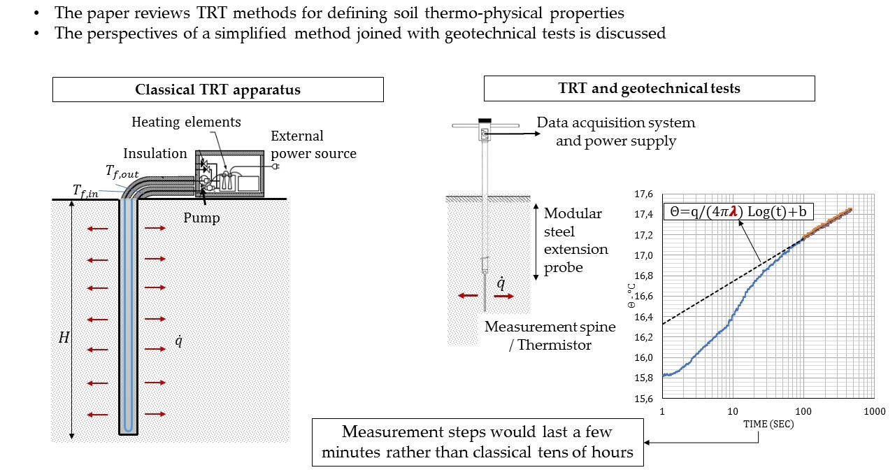
These devices are typically employed in laboratory activities but they are also used for in situ investigations to characterize the composition of the soil (e.g., sand, clay, rocks) and to assess groundwater effects. The measurement process is quite similar to the one used in HC-TRT, with the advantage of not requiring a borehole. The top of the instrument is the measurement unit, consisting of a steel spine that contains the thermistor. Once the probe is inserted in the ground, it acts as both a heating and measurement device: the thermistor generates a constant heat through the Joule effect and the measurement of its electrical resistance allows for the evaluation of the probe temperature evolution.
Figure 8 shows the typical output of the instrument (i.e., the probe temperature
, expressed in °C) and the processing method used to obtain the thermal conductivity value, which is practically the same one as that previously shown in
Figure 4 for a standard TRT. The main advantages of these instruments are the duration of the measurement (a few minutes) and a more accurate direct measurement of both the thermal power and temperature without being affected by the typical errors occurring in the measure of fluid flows.
However, in the current state, the employment of such instruments is not very significant for GSHP applications as the short length of the measurement spine (of about 20–30 cm) only allows for a local investigation of the ground’s thermal properties. A possible development involves the employment of longer thermistors or using modular steel probes as a support for the thermo-active spine (see
Figure 7b). In the latter case, the size of the thermistor can be kept the same but the measurement can be performed by inserting the instrument in the ground at regular depth steps (e.g., every five meters). At each stop, the measurement can be performed in a few minutes; then, the probes will be moved up to the next depth using manual or small drills, obtaining an average data for the thermal conductivity within a reduced duration (the duration of the test is a few minutes). In such a way, it would be possible to obtain a trade-off between the time required, accuracy of the measurement, and the investigated ground depth. Additionally, the duration of this test would be coherent with the already-mentioned geotechnical analysis for structural purposes. The same operators can perform the thermal test at the same time while other geotechnical machines operate.
Figure 8 shows the typical output of the instrument; we note that the temperature of the thermistor evolves with a trend similar to the one shown in
Figure 4. The interpretation of experimental data is the same as that already discussed for classical TRT: in the illustrative case shown in
Figure 4, the linear heat power is equal to
q’ = 4.52 W/m and the resulting thermal conductivity
λ = 1.98 W/m·K. The main advantages of this method are the duration of the measurement (a few minutes) and the accurate control and the direct measurement of both the thermal power and temperature, without being affected by the typical errors occurring in the measurement of fluid flows. On the contrary, in this case, the reduced depth of the probe only allows for a local investigation of the ground’s thermal properties. However, this problem can be superated by using a longer probe or testing different points of measurement. The method discussed in the present section, of which nowadays no industrial development is available, could surely be a future line of work and this paper only provides a preliminary approach.
7. Conclusions
In the present paper, some recent results connected to the application of classical and recently enhanced TRT methods have been reviewed and discussed. The evolution of the basic method was analyzed to increase the future application of the procedure.
Experimental investigation of ground thermal properties is always recommended to limit the oversizing of ground heat exchangers due to the application of approximate rules of thumb. The following developments of the current TRT procedure are desirable:
Gathering the vertical profiles of ground thermal properties is needed for the BHE’s design optimization.
Lowering the time and costs of TRT for low-capacity systems (e.g., single houses), even with less accurate methods and only investigating the shallow layers of the ground.
Connecting the TRT procedure with the mandatory geotechnical tests. In fact, the drilling and the investigation of the ground are already performed through several procedures, such as the standard penetration test (SPT), cone penetration test (CPT), and seismic prospecting in a hole (down-hole or cross-hole). These tests involve some tens of meters of depth and are also appropriate for thermal investigations.
Following these points, a further method based on the connection of TRT tests with standard geotechnical or hydrogeological tests, which is currently mandatory in different countries before building construction, has been proposed and discussed.
The method is economical (since it is joined with mandatory tests) and is expected to be less time-consuming than other testing and theoretical methods, including a conventional TRT. It is based on the application of a recently proposed evolution of TRT, such as the TRT-HC, while the analysis of the data is based on the utilization of the ε-NTU method, a well-known method for the analysis of the heat exchangers.
The main idea we propose is a possible connection of the thermal characterization of the ground with mandatory geotechnical surveys that are usually required before a new building construction for seismic protection. Therefore, the thermal properties of soils (thermal conductivity and thermal diffusivity) can be estimated together with other key geotechnical properties, and all the analyses can be in the charge of a single company, with remarkable time and cost savings. A brief approach of the theoretical procedure is provided and this could be developed in the future.


