Energy Shaping Control for Wireless Power Transfer System in Automatic Guided Vehicles


Abstract
:1. Introduction
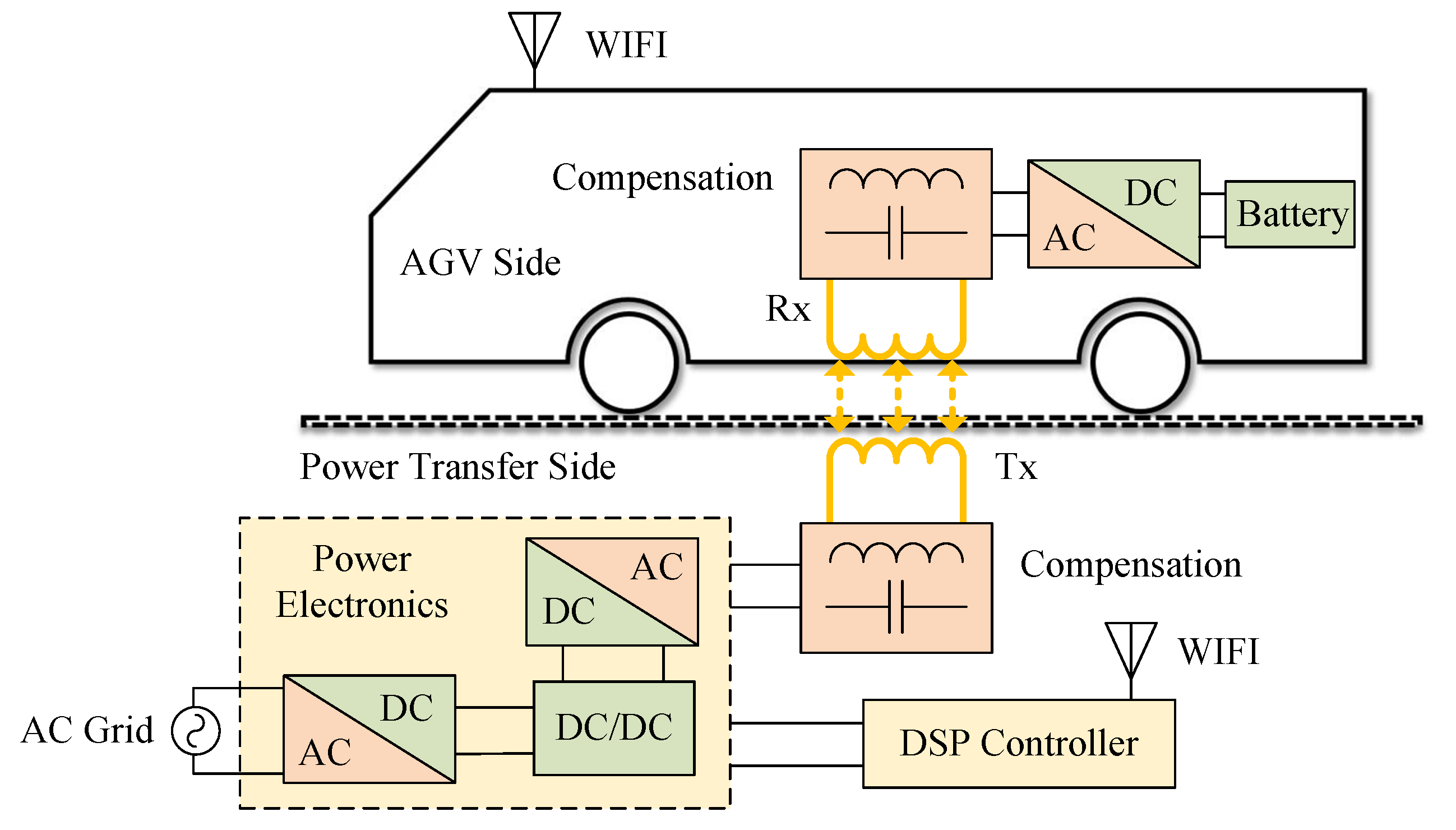
2. Modelling Wireless Charging System
3. Energy Shaping Control with Dynamical Regulation of Charging Power
3.1. Energy Shaping via IDA-PBC
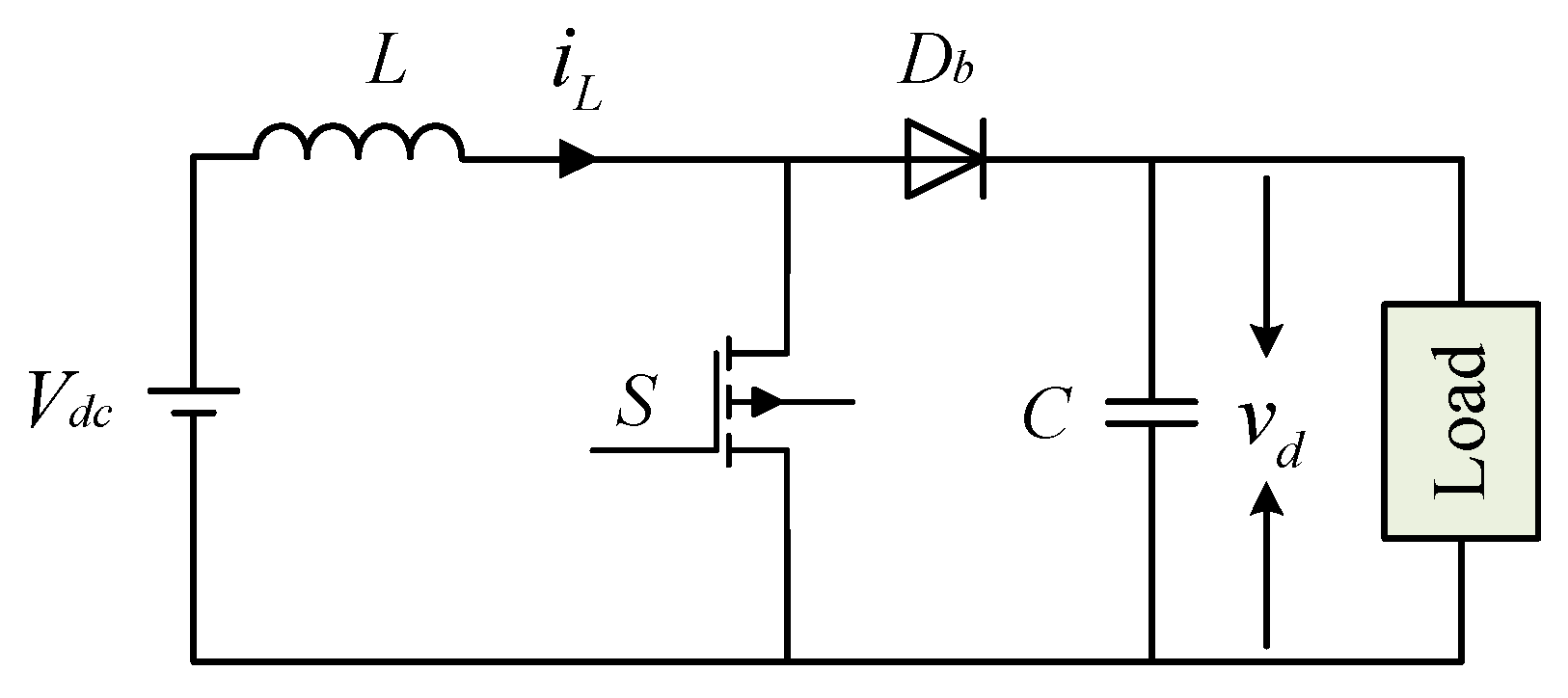
3.2. Dynamic Regulation of Charging Power
4. Simulation and Experiment
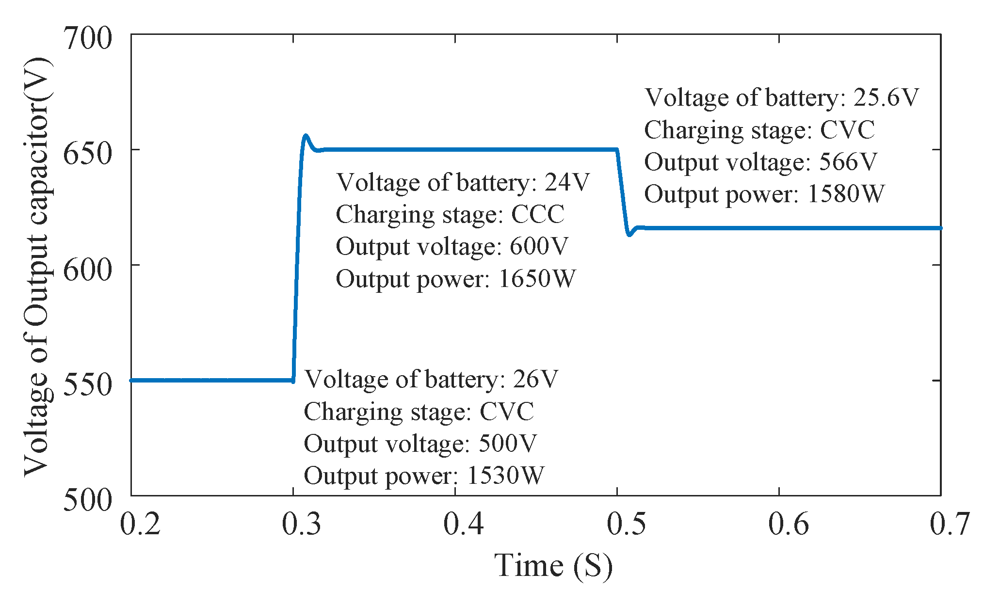
4.1. Simulation Results
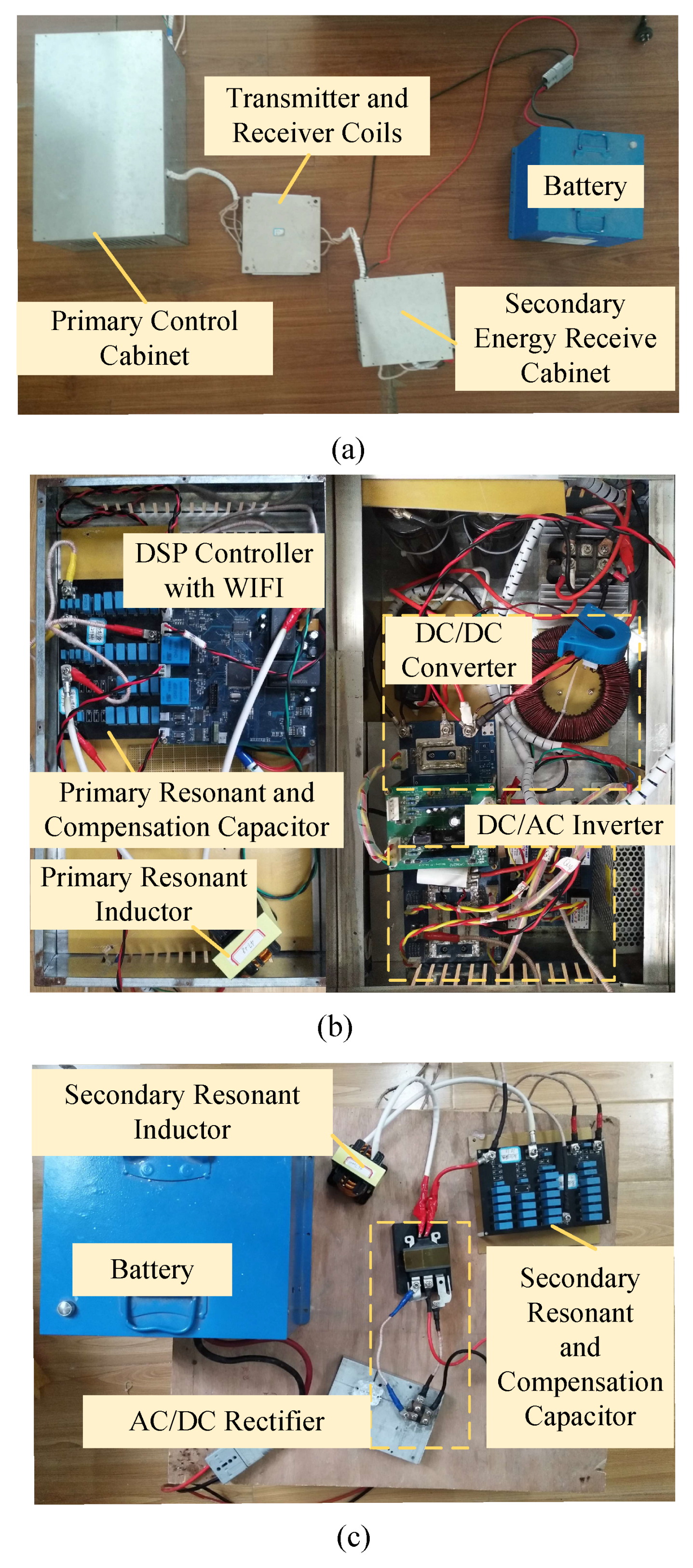
4.2. Experimental Results
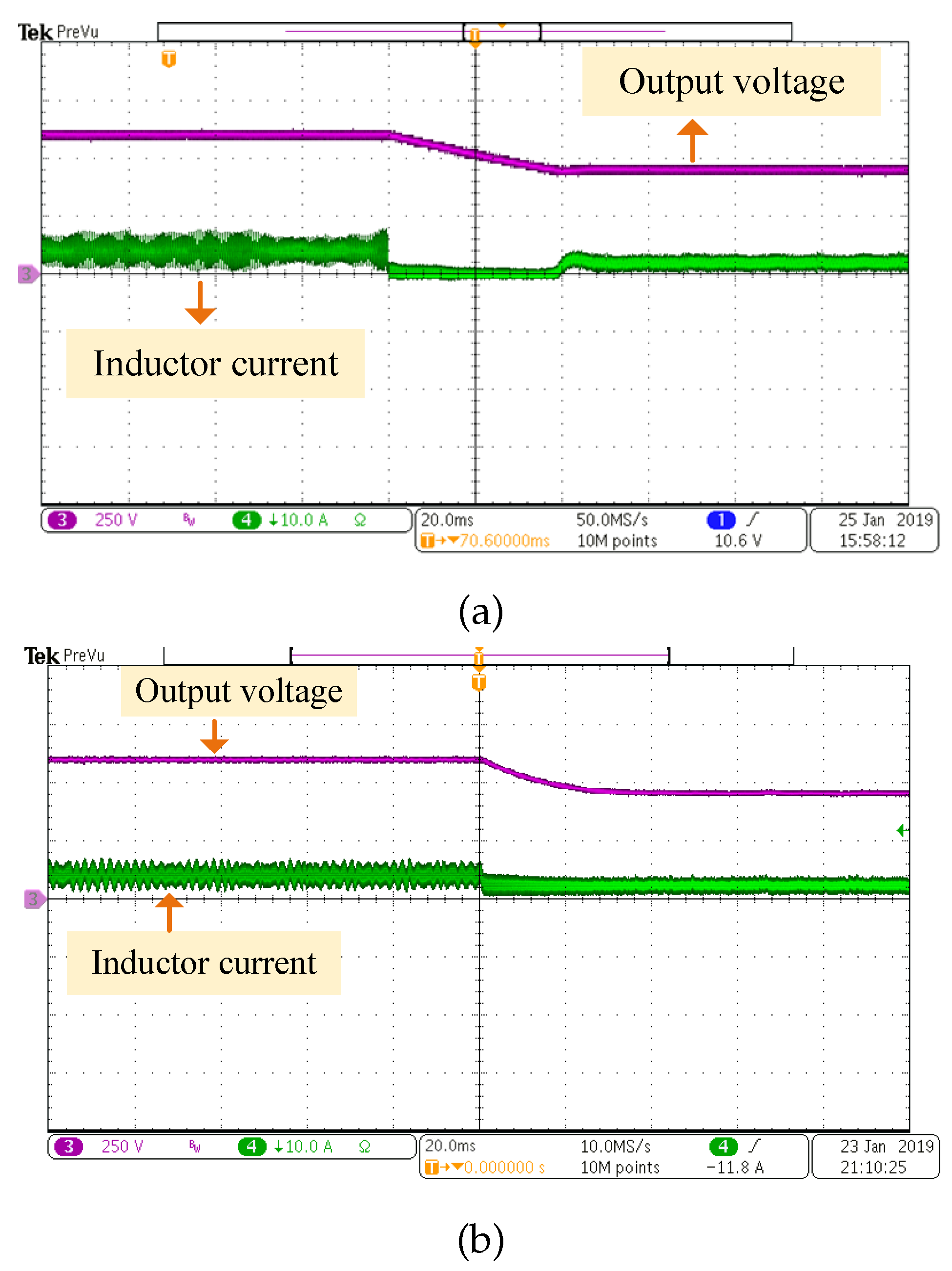
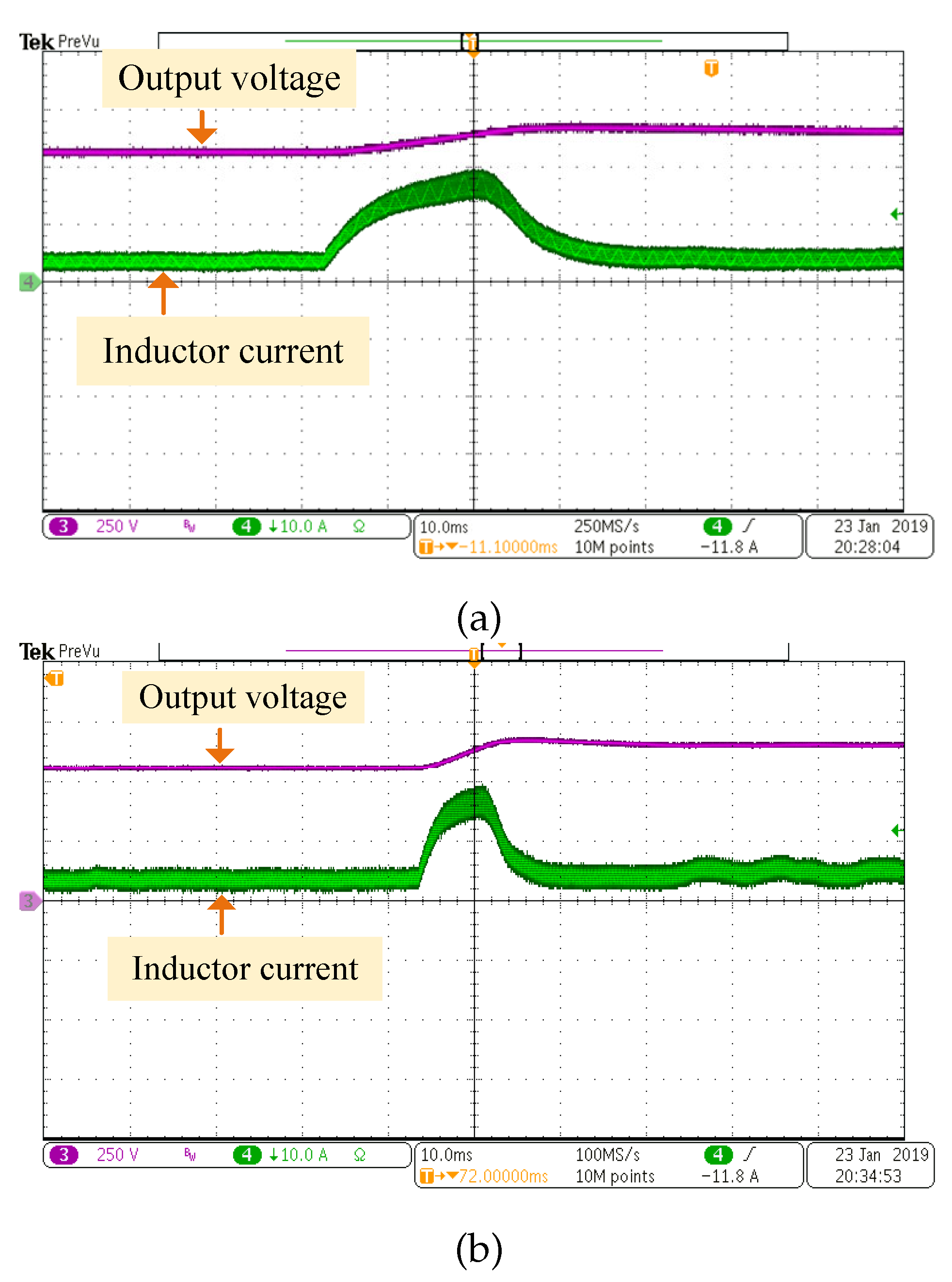
4.2.1. Dynamic Performance Experiment
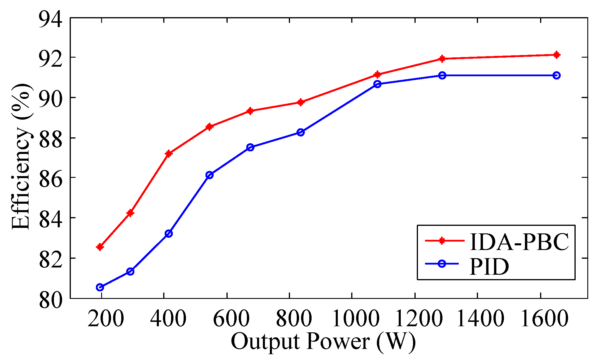
4.2.2. Charging Power Efficiency
5. Conclusions
Author Contributions
Funding
Conflicts of Interest
Abbreviations
| WPT | wireless power transfer |
| AGVs | automatic guided vehicles |
| IDA-PBC | Interconnection and damping assignment passivity-based control |
| PBC | passivity-based control |
| EVs | electric vehicles |
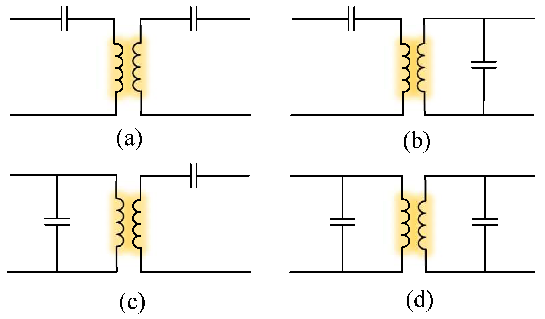
| SS | series–series |
| SP | series–parallel |
| PS | parallel–series |
| PP | parallel–parallel |
| ZVS | zero voltage switch |
| DD | double-D |
| PWM | pulse width modulation |
| CCM | continuous conduction mode |
| DCM | discontinuous conduction mode |
| PCH | port-controlled hamiltonian |
| CCC | constant current charge |
| CVC | constant voltage charge |
| SOC | state of charge |
| DSP | digital signal processor |
References
- Kongezos, V.K.; Allen, C.R. Wireless communication between AGVs (autonomous guided vehicles) and the industrial network CAN (controller area network). In Proceedings of the 2002 IEEE International Conference on Robotics and Automation (Cat. No.02CH37292), Washington, DC, USA, 11–15 May 2002; pp. 434–437. [Google Scholar]
- Hao, Y.; Wang, J.; Liu, Y. Research on wireless power transfer system of automated guided vehicle based on magnetic coupling resonance. In Proceedings of the 2019 22nd International Conference on Electrical Machines and Systems (ICEMS), Harbin, China, 11–14 August 2019; pp. 1–4. [Google Scholar]
- Umar, U.A.; Ariffin, M.K.A.; Ismail, N.; Tang, S.H. Hybrid multiobjective genetic algorithms for integrated dynamic scheduling and routing of jobs and automated-guided vehicle (AGV) in flexible manufacturing systems (FMS) environment. Intern. J. Adv. Manuf. Technol. 2015, 8, 2123–2141. [Google Scholar] [CrossRef]
- Zhang, G.; Pan, Z. The application research of mobile robots and wireless sensor network in laser automatic guided vehicles. In Proceedings of the 2011 Third International Conference on Measuring Technology and Mechatronics Automation, Shangshai, China, 6–7 January 2011; pp. 708–711. [Google Scholar]
- Huang, S.; Lee, T.; Li, W.; Chen, R. Modular on-road AGV wireless charging systems via interoperable power adjustment. IEEE Trans. Ind. Electron. 2019, 66, 5918–5928. [Google Scholar] [CrossRef]
- Zhang, H.; Zhu, C.; Lu, F. A compact and low-distortion inductive charging system for automatic guided vehicles based on LCC compensation and integrated magnetic coupler. In Proceedings of the 2019 IEEE Transportation Electrification Conference and Expo (ITEC), Detroit, MI, USA, 19–21 June 2019; pp. 1–5. [Google Scholar]
- Song, C.; Kim, H.; Jung, D.H.; Kim, J.J.; Kong, S.; Kim, J.; Ahn, S.; Kim, J.; Kim, J. Low EMF and EMI design of a tightly coupled handeld resonant magnetic field (HH-RMF) charger for automotive battery charging. IEEE Trans. Electromagn. Compat. 2016, 4, 1194–1206. [Google Scholar] [CrossRef]
- Zaheer, A.; Covic, G.A.; Kacprazak, D. A bioplar pad in a 10 kHz 300-W distributed IPT system for AGV applications. IEEE Trans. Ind. Electron. 2014, 7, 3288–3301. [Google Scholar] [CrossRef]
- Matsumoto, H.; Shibako, Y.; Neba, Y. Contacless power transfer syatem for AGVs. IEEE Trans. Ind. Electron. 2018, 65, 251–260. [Google Scholar] [CrossRef]
- Jiang, C.; Chau, K.T.; Liu, C.; Lee, C.H.T.; Han, W.; Liu, W. Move-and-charge system for automatic guided vehicles. IEEE Trans. Magn. 2018, 54, 1–5. [Google Scholar] [CrossRef]
- Trung, N.T.N.K.; Minh, T.T. Control the constant current/voltage charging mode in the wireless charging system for electric vehicle with LCC compensation circuit. In Proceedings of the 2019 IEEE Vehicle Power and Propulsion Conference (VPPC), Hanoi, Vietnam, 14–17 October 2019; pp. 1–5. [Google Scholar]
- Miller, J.M.; Omer, O.C.; Madhu, C. Primary side power flow control of wireless power transfer for electric vehicle charging. IEEE J. Emerg. Sel. Top. Power Electron. 2014, 3, 147–162. [Google Scholar] [CrossRef]
- Patil, D.; McDonough, M.K.; Miller, J.M.; Fahimi, B.; Balsara, P.T. Wireless power transfer for vehicular applications: Overview and challenges. IEEE Trans. Transp. Electrif. 2017, 4, 3–37. [Google Scholar] [CrossRef]
- Tan, T.; Chen, K.; Jiang, Y.; Lin, Q.; Yuan, L.; Zhao, Z. A bidirectional wireless power transfer system control strategy independent of real-time wireless communication. IEEE Trans. Ind. Appl. 2019, 56, 1587–1598. [Google Scholar] [CrossRef]
- Kan, T.; Lu, F.; Nguyen, T.D.; Mercier, P.P.; Mi, C.C. Integrated coil design for EV wireless charging systems using LCC compensation topology. IEEE Trans. Power Electron. 2018, 33, 9231–9241. [Google Scholar] [CrossRef]
- Zhang, W.; Mi, C.C. A double-sided LCC compensation network and its tuning method for wireless power transfer. IEEE Trans. Veh. Technol. 2015, 64, 2261–2273. [Google Scholar]
- Li, Z.; Zhu, C.; Jiang, J.; Song, K.; Wei, G. A 3-kW wireless power transfer system for sightseeing car supercapacitor charge. IEEE Trans. Power Electron. 2017, 32, 3301–3316. [Google Scholar] [CrossRef]
- Pantic, Z.; Bai, S.; Lukic, S.M. ZCS LCC-compensated resonant inverter for inductive-power-transfer application. IEEE Trans. Ind. Electron. 2011, 58, 3500–3510. [Google Scholar] [CrossRef]
- Zhang, F.; Zhang, J.; Qian, Y.J. A multi-node rechargeable algorithm via wireless charging vehicle with optimal traveling path in wireless rechargeable sensor networks. In Proceedings of the 2018 Tenth International Conference on Ubiquitous and Future Networks (ICUFN), Prague, Czech Republic, 3–6 July 2018. [Google Scholar]
- Deng, J.; Li, W.; Nguyen, T.D.; Li, S.; Mi, C.C. Compact and efficient bipolar coupler for wireless power chargers: Design and analysis. IEEE Trans. Ind. Electron. 2011, 30, 6130–6140. [Google Scholar] [CrossRef]
- Nguyen, T.; li, S.; Li, W.; Mi, C.C. Feasibility study on bipolar pads for efficient wireless power chargers. In Proceedings of the 2014 IEEE Applied Power Electronics Conference and Exposition-APEC 2014, Fort Worth, TX, USA, 16–20 March 2014; pp. 1676–1682. [Google Scholar]
- Chen, Y.; Yang, N.; Yang, B.; Dai, R.; He, Z.; Mai, R.; Gao, S. Two-three-coil hybrid topology and coil design for WPT system charging electric bicycles. IET Power Electron. 2019, 12, 2501–2512. [Google Scholar] [CrossRef]
- Zaheer, A.; Covic, G.A.; Kacprzak, D. Magnetic intergration of LCC compensation resonant converter for inductive power transfer applications. IEEE Trans. Ind. Electron. 2014, 61, 3288–3301. [Google Scholar] [CrossRef]
- Zhang, Z.; Pang, H.; Georgiadis, A.; Cecati, C. Wireless Power Transfer-An Overview. IEEE Trans. Ind. Electron. 2019, 4, 1044–1058. [Google Scholar] [CrossRef]
- Chen, W.; Chen, Q.; Zhang, L.; Long, R. Passivity-based controller of dynamic wireless power transfer system. In Proceedings of the 2019 34rd Youth Academic Annual Conference of Chinese Association of Automation (YAC), Jinzhou, China, 6–8 June 2019; pp. 381–386. [Google Scholar]
- Zeng, J.; Zhang, Z.; Qiao, W. An interconnection and damping assignment passivity-based controller for a DC/DC boost converter with a constant power load. IEEE Trans. Ind. Appl. 2014, 50, 2314–2322. [Google Scholar] [CrossRef]
- Ortega, R.; Garcia–Canseco, E. Interconnection and damping assignment passivity-based control: A survey. Eur. J. Control 2004, 10, 432–450. [Google Scholar] [CrossRef]
- Son, Y.; Kim, I.H. Complementary PID controller to passivity-based nonlinear control of boost converters with inductor resistance. IEEE Trans. Control Syst. Technol. 2011, 20, 826–834. [Google Scholar] [CrossRef]
- Petrovic, V.; Ortega, R.; Stankovic, A.M. Interconnection and damping assignment approach to control of PM synchronous motors. IEEE Trans. Control Syst. Technol. 2001, 50, 811–820. [Google Scholar] [CrossRef]
- Li, H.; Fang, J.; Chen, S.; Wang, K.; Tang, Y. Pulse density modulation for maximum efficiency point tracking of wireless power transfer systems. IEEE Trans. Power Electron. 2018, 33, 5492–5501. [Google Scholar] [CrossRef]
- Papula, L. Papula Mathematische Formelsammlung; Springer: Wiesbaden, Germany, 2017. [Google Scholar]


| Parameter | Value | Unit |
|---|---|---|
| Primary resonant inductor | 47.10 | |
| Secondary resonant inductor | 46.81 | |
| primary resonant capacitor | 74.44 | nF |
| Secondary resonant capacitor | 74.90 | nF |
| Primary compensation capacitor | 97.93 | nF |
| Secondary compensation capacitor | 101.74 | nF |
| Primary coil | 82.90 | |
| Secondary coil | 81.27 | |
| Mutual inductor M | 26.28 | |
| Resonant frequency f | 85 | kHz |
| Nominal gap of two coils h | 50 | mm |
| Voltage of the battery | 21.2∼28.2 | V |
| Switching frequency of the DC/DC converter | 20 | kHz |
| Capacitor of the DC/DC converter C | 400 | F |
| Inductor of the DC/DC converter L | 2500 | |
| Input voltage | 310 | V |
| Charging Process | Specifications | PID | IDA-PBC |
|---|---|---|---|
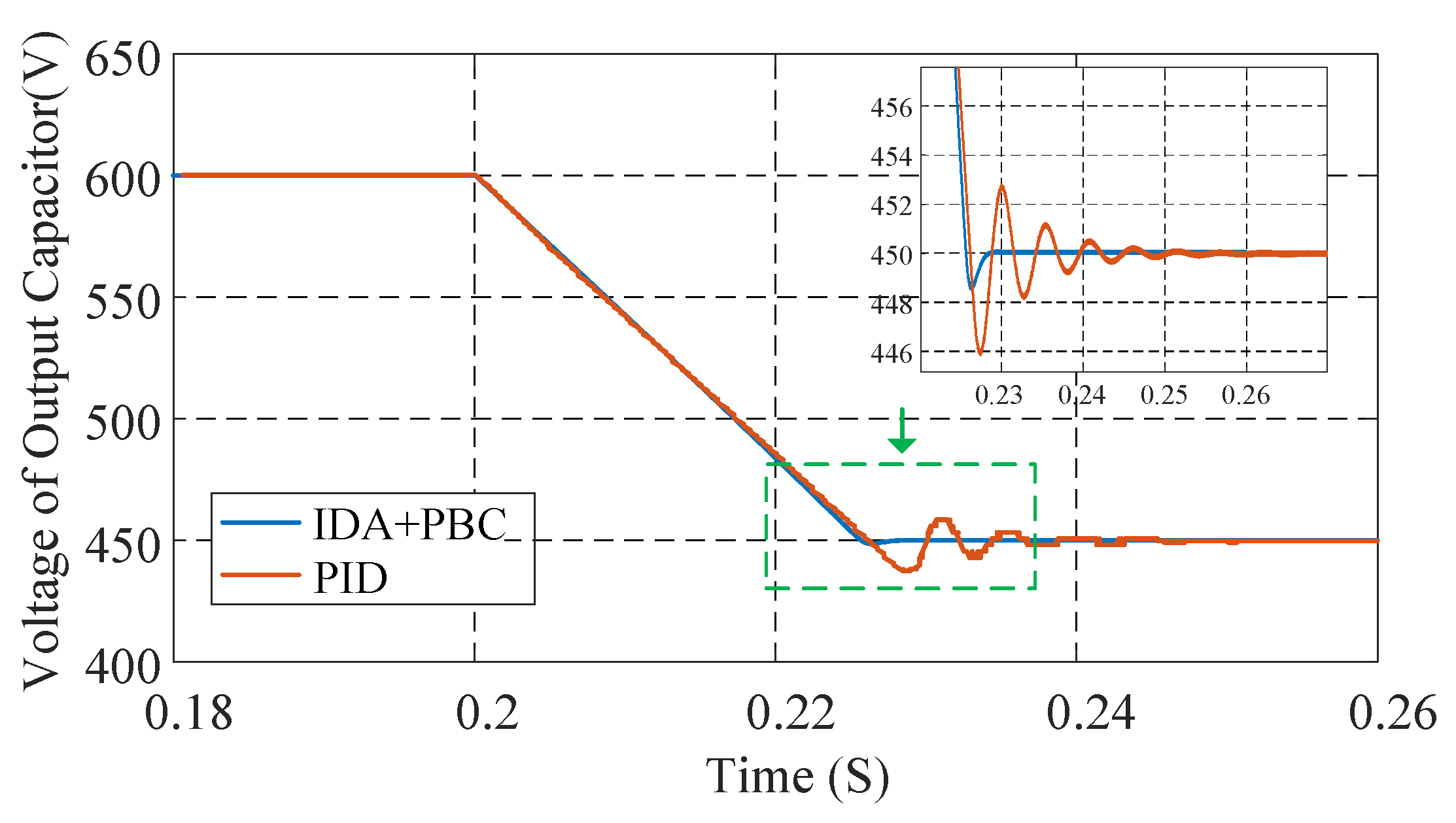
| Step-down | Transient time | 48.3 ms | 23.6 ms |
| Percentage overshoot | 0.89% | 0.22% | |
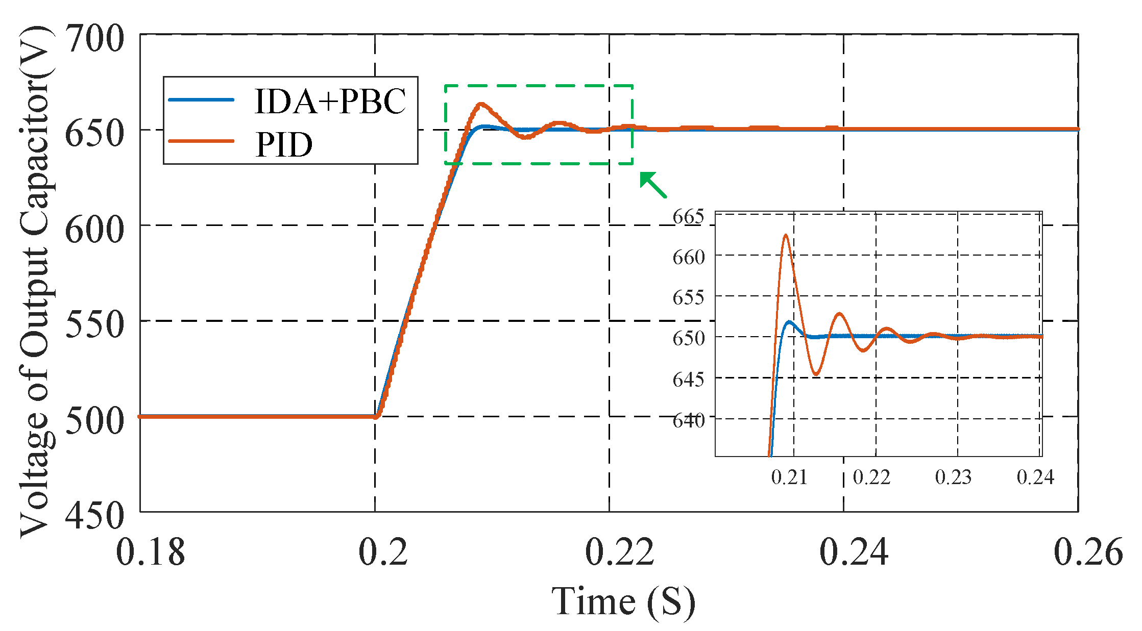
| Step-up | Transient time | 30 ms | 11 ms |
| Percentage overshoot | 2.15% | 0.31% |
| Parts | Specifications | Quantity |
|---|---|---|
| Battery | 24 V/40 Ah | 1 |
| DSP controller | TMS320F28335 | 1 |
| IGBT in boost converter S | IKW40N120H3 | 1 |
| Diodes in boost converter | 40EPF06 | 1 |
| IGBT driver board | DA102D1 | 1 |
| Mosfets in DC/AC inverter ,,, | SCH208KE | 4 |
| Diode in AC/DC rectifier , | DSEI 2*61-10B | 1 |
© 2020 by the authors. Licensee MDPI, Basel, Switzerland. This article is an open access article distributed under the terms and conditions of the Creative Commons Attribution (CC BY) license (http://creativecommons.org/licenses/by/4.0/).
Share and Cite
Chen, W.; Liu, J.; Chen, S.; Zhang, L. Energy Shaping Control for Wireless Power Transfer System in Automatic Guided Vehicles. Energies 2020, 13, 2959. https://doi.org/10.3390/en13112959
Chen W, Liu J, Chen S, Zhang L. Energy Shaping Control for Wireless Power Transfer System in Automatic Guided Vehicles. Energies. 2020; 13(11):2959. https://doi.org/10.3390/en13112959
Chicago/Turabian StyleChen, Wenjie, Jia Liu, Si Chen, and Liyan Zhang. 2020. "Energy Shaping Control for Wireless Power Transfer System in Automatic Guided Vehicles" Energies 13, no. 11: 2959. https://doi.org/10.3390/en13112959
APA StyleChen, W., Liu, J., Chen, S., & Zhang, L. (2020). Energy Shaping Control for Wireless Power Transfer System in Automatic Guided Vehicles. Energies, 13(11), 2959. https://doi.org/10.3390/en13112959