Abstract
Self-circulation wellbore is a new technique for geothermal development in hot dry rocks (HDR), which uses a U-shape channel composed of tubing and casing as the heat exchanger. In this study, a self-circulation wellbore in HDR on a laboratory scale was built, and a serial of experiments were conducted to investigate the heat exchange law and the influencing factors on the heat mining rate of the wellbore. A similarity analysis was also made to estimate the heat-mining capacity of the wellbore on a field scale. The experimental results show that the large thermal conductivity and heat capacity of granite with high temperature can contribute to a large heat-mining rate. A high injection rate can cause a high convective heat transfer coefficient in wellbore, while a balance is needed between the heat mining rate and the outlet temperature. An inner tubing with low thermal conductivity can significantly reduce the heat loss to the casing annulus. The similarity analysis indicates that a heat mining rate of 1.25 MW can be reached when using a 2000 m long horizontal well section in a 150 °C HDR reservoir with a circulation rate of 602.8 m3/day. This result is well corresponding to the published data.
1. Introduction
Geothermal energy is one of the most promising renewable energies [1]. Generally, geothermal resources mainly have five types, including vapor-dominated reservoirs, water-dominated reservoirs, geopressured geothermal reservoirs, hot dry rocks, and magma systems. In terms of the reservoir temperature, the geothermal energy can be classified into high-temperature geothermal energy (>150 °C), medium-temperature geothermal energy (90–150 °C) and low-temperature geothermal energy (<90 °C). The former two can be used for power generation while the last one is mostly for direct heat utilization. Hot dry rocks (HDR) is a kind of hot rock without water or steam. They mainly consist of various metamorphic or crystalline rocks and locate at a depth of 3–10 km. The temperature of rocks is up to 150–650 °C [2]. Hot dry rocks (HDR) has advantages of high temperature, wide distribution and large reserve, which has been becoming an important field for the geothermal development [2,3,4]. Due to the low permeability and porosity of the rocks at depths, a large-scale hydraulic fracturing is usually applied to construct an artificial reservoir for fluid circulation to develop HDR geothermal energy [5,6]. This scheme is called enhanced geothermal system (EGS), which is currently the main method to utilize the HDR geothermal energy [2]. The EGS method can also be used in hydrothermal reservoirs with low permeability. Although EGS has been studied for about 40 years, the following problems still exist: (1) the heat transmission fluid loss into the ambient formation; (2) the blockage or closure of the fractures because of the fluid-rock reaction and proppant failure; (3) the high economic cost; (4) the induced seismic and environmental issues [7,8]. In recent years, a novel technique of self-circulation wellbore for HDR geothermal development has been proposed, which can avoid well the problems of the EGS [9,10,11,12,13]. In this technique, the heat transfer fluid is injected into the annulus between tubing and casing to extract the heat from the high-temperature formation during its downward flowing. After the heat transfer fluid reaches the bottom of the annulus, it will return to the ground through the inner tubing. If the tubing has a good heat preservation capability, the hot heat transfer fluid can be obtained at the wellhead for utilization.
For the self-circulation wellbore technique, many related studies have been conducted [9,10,11,12,13,14,15,16,17,18,19,20,21,22]. Kujawa et al., established a heat transfer model of a concentric-tube heat exchanger in geological well, and the influence of the inside pipe insulation and flow rate on the outlet temperature and heat power was analyzed [9]. Bu et al. developed a mathematical model for double-pipe heat exchangers transformed from abandoned oil and gas wells to describe the heat transfer from rocks to fluid, and the heat and net power were predicted [10]. Richard et al., Beier et al., Henrik et al. and Nian et al. established heat transfer models for the coaxial wellbore heat exchanger in the ground-source heat pumps (GSHP) system, and compared the prediction results with the distributed thermal response test (DTRT) [12,13,14,18,19]. David et al. built a set of vertical coaxial borehole heat exchangers using standard geothermal piping materials and the heat mining performance of the exchanger with different inner diameters was compared [20]. McDaniel et al. conducted a DTRT under heterogeneous geological conditions, and combined the result with the thermophysical measurements of cores and the new data analysis technique to provide a detailed description of heat transfer changes underground [21]. Dai et al. made use of a deep geothermal well in Tanggu (China), and carried out a geothermal production test by adopting a downhole coaxial open-loop design, which indicated the good effect of downhole configuration on the heat extraction in deep geothermal reservoirs, and had a heat extraction capacity much higher than the common exchanger [22].
To summarize the research status of the wellbore self-circulation technique, it can be seen that: (1) there have been many similar researches on self-circulation wellbore such as the concentric pipe, but they are mainly aimed at the shallow GSHP system with depths less than 200 m or abandoned oil and gas wells transformed for heat production, and usually direct use of heat is the main target; (2) For the HDR, only limited researches focus on the heat mining capacity evaluation by the wellbore heat transfer model, but the results lack experimental verification. Hence, although current researches have a certain reference significance, it is difficult to guarantee that the present law of heat exchange in wellbore obtained can be applied directly in the HDR reservoirs which have deeper depth, denser lithology and higher temperature. It is necessary to carry out experiments on the heat extraction from HDR by self-circulation wellbore, but field experimental study is limited at present.
In this study, an experimental device on a laboratory scale was built to simulate the heat exchange process in the local self-circulation wellbore in the HDR reservoir. Taking water as the heat transfer fluid, a series of laboratory experiments were carried out to reveal the law of heat exchange in wellbore and the influence of different factors on the heat mining rate of water. Finally, a similarity analysis was conducted to estimate the heat-mining capacity of self-circulation wellbore on a field scale.
2. Experimental Section
2.1. Equipment
The built heat exchanger of self-circulation wellbore on a laboratory scale is shown in Figure 1. It mainly consists of a heat exchange tube, geothermal reservoir system, fluid circulation system, and data monitoring system.
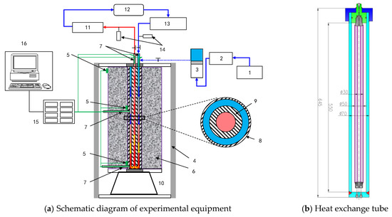
Figure 1.
Wellbore self-circulation experiment system. In Figure 1a: (1) water tank, (2) advection pump, (3) intermediate container, (4) thermotank, (5) temperature sensor (four points, probe type), (6) granite jacket or quartz sand cylinder, (7) temperature sensor (three points, patch type), (8) outer casing, (9) inner tubing (hollow inside, filled with thermal conductivity materials or vacuum), (10) pedestal, (11) low-temperature water bath, (12) buffer tank, (13) plunger metering pump, (14) pressure sensor (two points), (15) data collection box, and (16) computer.
(1) The heat exchange tube is composed of an outer casing and an inner tubing (304 stainless steel). The casing is 645 mm long with an effective length of 550 mm for heat transfer. The outer and inner diameters of the casing are 70 mm and 50 mm, respectively. The tubing is 550 mm long, and the outer and inner diameters are 30 mm and 10 mm, respectively. The tubing wall is hollow, which can be filled with different materials or vacuum to change the thermal conductivity of the tube wall.
(2) The geothermal reservoir system includes the granite jacket, quartz sand cylinder and the thermotank. Both the granite jacket and quartz sand cylinder have a diameter of 22 cm, which can cover the whole outside wall of the casing to transmit the heat from the sand or granite to the wellbore. The thermotank is used to keep the temperature of the granite jacket and quartz sand cylinder at the designed value (20 to 200 °C).
(3) The fluid circulation system is used to circulate the heat transmission fluid. It includes the low-temperature water bath (−5–90 °C), the buffer tank (200 mL), and the plunger metering pump with a flow rate control range of 0–32 L/h (accuracy rate is 95%) and a max working pressure of 25 MPa.
(4) The data monitoring system is used to monitor the fluid temperature and pressure in the circulation system. Two pressure sensors (± 0.01 MPa) are used to monitor the pressures at the outlet and the inlet of the heat exchange tube. Seven temperature sensors (± 0.15 °C) are used to monitor the temperatures at the inlet and the outlet of the heat exchange tube, the middle and the bottom of the annulus and the outer wall of the casing, and the top of the outer wall of the granite jacket (only used to monitor the temperature drop front when the effect of water injection rate is assessed). In addition, a data collection box and a computer are used to record the fluid P-T data in the system in time.
2.2. Materials
(1) Heat transfer fluid: the conventional water was used, which is cheap, has a large specific heat capacity and has been widely used in various heat exchange equipment [23].
(2) Heat storage media: three kinds of heat storage media around the heat exchange tube were designed, including the granite jacket, quartz sand cylinder and air at ambient conditions (Figure 2). The granite jacket has an average outside diameter of 22 cm, an inner diameter of 7 cm and a height of 55 cm. It can wrap on the outer casing as an HDR reservoir. The gap between the casing and the granite jacket was filled with a specific mud with high thermal conductivity, which is beneficial to the heat transfer between the granite jacket and the heat exchange tube. For comparison, the quartz sand with an average particle size of 0.15 mm was used to simulate the sandstone geothermal reservoir. The quartz sand was filled in a stainless-steel cylinder with a diameter of 22 cm and a height of 55 cm, and the heat exchange tube was set up in the center of the cylinder. Besides, the air ambient was also considered as a background case.
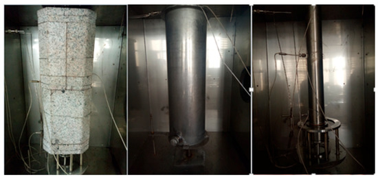
Figure 2.
The heat exchange tube with granite jacket, quartz sand cylinder or air ambient (from left to right).
The thermal properties of various fluids, heat storage media as well as the heat exchange tube and the sand cylinder are listed in Table 1, which would be used in the experimental result analysis.

Table 1.
Thermal properties of fluids, heat storage media and stainless-steel tube at 0.1 MPa and 20 °C.
2.3. Procedures
Taking the basic case for example, the main procedures of the experiment are as follows:
- Use the advection pump to inject the low-temperature water from the intermediate container into the fluid circulation system at a rate of 10 mL/min, drive all the air out of the circulation system, then close the outlet of the loop, and continue injecting the water into the loop to increase the pressure to 10 MPa, then close the inlet of the loop.
- Turn on the thermotank to heat and maintain the heat exchange tube with granite jacket or sand cylinder at 150 °C, and set the cooling temperature of the low-temperature water bath to 20 °C.
- When the pressure and temperature in the heat exchange tube reaches steady state (the additional pressure may need to be released due to the temperature increase), start the plunger metering pump to circulate the water in the heat exchange tube at a rate of 106.7 mL/min. The cold water flows into the casing annulus and hot water comes out from the inner tubing.
- Open the computer and record the temperature and pressure changes in the heat exchange system every 10 s. When the outlet temperature reaches steady state 2 h later, the experiment is over.
According to the monitored data, the parameters that characterize the heat exchange performance of the self-circulation wellbore, including the heat mining rate at the outlet, the wellbore heat flux, the average convective heat transfer coefficient of the wellbore, and the heat loss rate from the bottom of the annulus to the outlet of the inner tubing in the heat mining process can be calculated.
The heat mining rate at the outlet (Qw, W) is determined by the inlet and outlet temperatures of the heat exchange tube and the volumetric flow rate of the water [24], which is calculated as follows:
where Vw is the volumetric flow rate of water, m3/s; ρw is the density of water, kg/m3; cw is the specific mass heat capacity of water at constant pressure, J/(kg·K); Tin and Tout are the temperatures of water at the inlet and outlet of the heat exchange tube, respectively, °C.
In order to avoid the variation of heat flux at different radius due to the variation of cross-sectional area, the heat flux (qw, W/m) is often calculated according to unit pipe length in engineering for the convenience of calculation [14]. Hence, taking the average heat flux of the casing annulus, for example, it can be calculated as follows:
where cvw the volumetric heat capacity of the water, J/(m3·K); Tbottom is the temperature at the bottom of the casing annulus, °C; Lc is the length of the heat transfer segment (casing), m.
When the outlet temperature reaches steady state, the heat produced at the outlet is equal to the heat transferred through the casing wall from the heat storage media, regardless of the influence of the heat stored in the casing and tubing. Hence, the average convective heat transfer coefficient (hw, W/(m2∙K)) between the casing wall and the water in the annulus can be calculated using the following formula [25]:
where ΔTm is the average heat transfer temperature difference between the water and the inner wall of the casing, °C; dci is the inner diameter of the casing, m. ΔTm can be calculated as follows [25]:
where Tbottom is the water temperature at the bottom of the casing annulus, °C; Tci is the average inner wall temperature of the casing, °C, which can be calculated according to the average temperature of the outer wall of the casing. The formula is as follows [25]:
where Tco is the average temperature of the casing outer wall, °C; Ac is the average wall area of the casing, m2; dco is the outer diameter of the casing, m; λc is the thermal conductivity of the casing, W/(m·K).
In addition, for the rate of heat loss (ftloss, %) from the inner tubing to the casing annulus when the water flows upward in the inner tubing, it can be calculated using the following equation:
2.4. Schemes
Due to the short length of the heat exchange tube, the built self-circulation wellbore is targeted to simulate the heat exchange process in a local well section to reveal the basic heat exchange law and the influence of different factors on the heat mining performance of water. The experimental schemes are shown in Table 2. Five influencing factors are assessed, including the reservoir type and temperature, inlet pressure, injection rate and the thermal conductivity of inner tubing. In the basic case, the granite jacket and vacuum tubing were used; the initial reservoir temperature and wellbore pressure were 150 °C and 10 MPa, respectively; the water injection rate was 107 mL/min with an annulus-in direction which has been proved that it is more efficient for heat mining [26]. Based on the monitored P-T data, the heat mining rate, heat flux, average convection heat transfer coefficient and heat loss of the wellbore were calculated for the wellbore heat exchange analysis. The effect of thermal short-circuiting in a small size tube will be analyzed in the assessment on the tubing thermal conductivity, and the temperature drop front movement in the granite jacket will be discussed in the injection rate experiments.
Table 2.
Experimental schemes of the heat exchange tube to simulate wellbore self-circulation.
3. Experimental Results and Analysis
3.1. The Basic Law of Heat Exchange in the Self-Circulation Wellbore
The experimental results at the basic condition are taken as an example to analyze the basic law of heat exchange in the self-circulation wellbore.
(1) Temperature and pressure monitored
The changes in temperature and pressure in the heat exchange tube with time are shown in Figure 3. It can be seen from Figure 3a that the temperature of each monitoring point gradually reaches steady state after a rapid decrease in the early stage except the inlet temperature always kept at about 20 °C. In the first 20 min, the heat mined by water is mainly from the stainless tube and the inner part of the granite jacket. As the heat mining time increases, the front of the temperature drop in the granite jacket spreads to the distant reservoir, and the hot rock far away from the casing begins to conduct heat to the casing. The temperature field in the granite jacket (including the air around the granite jacket in thermotank) tends to stabilize gradually. Figure 3b indicates that the pressure fluctuation in the heat exchange tube is large in the early stage of heat mining due to the sharp temperature decrease in the wellbore, but after the heat mining process is stabilized, the pressure fluctuation also tends to be stable.
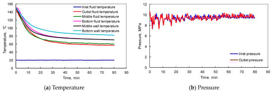
Figure 3.
The variation of temperature and pressure in the heat exchange tube with time.
(2) Heat mining rate and convective heat transfer coefficient
The calculated heat exchange parameters of the wellbore with time are shown in Figure 4. It can be seen that at the beginning of heat mining, due to the initial high temperature of the wellbore and granite jacket, both of the heat mining rate of water and the average convective heat transfer coefficient in the casing annulus are large, but decrease rapidly with time, and reach steady state about 20 min later (272 W and 301 W/(m2·K), respectively), while on the contrary, the heat loss in the inner tubing increases first and then tends to be stable (27.15%). As shown in Table 1, when the temperature is 150 °C, the heat stored in the heat exchange tube exceeds 14% of the heat stored in the granite jacket. Hence, the heat stored in the tube has a great influence on the heat mining performance in the early stage. The heat produced at a high rate in the early stage is mainly from the heat exchange tube, and a fast decrease of outlet liquid temperature is associated because of the similar heat capacity of tube to that of granite jacket and the much larger thermal conductivity of tube than that of granite jacket. High temperature of wellbore always brings a high mining rate, a high convective heat transfer coefficient as well as a low heat loss rate. However, the heat exchange law at the late stable stage is mainly affected by the boundary of granite jacket, which will be discussed in the injection rate experiment based on the monitored data.
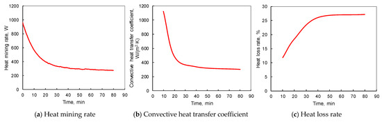
Figure 4.
The main heat exchange parameters of the heat exchange tube with time.
(3) The temperature distribution along the wellbore.
In the experiment, only the water temperatures at the inlet, outlet, and in the middle and bottom annulus of the casing were measured. It is enough to calculate the average heat exchange parameters in the wellbore using these data, but a detailed and accurate analysis of the heat flux and thermophysical properties of water along the wellbore needs a complete temperature profile of the wellbore. Because the difference calculation based on the monitoring data does not meet the requirement, the numerical simulation method was used to establish a heat exchange model of self-circulation wellbore to fit the measured temperature at typical time in the wellbore (CMG, 2012). The parameters used in the model are shown in Table 3. Radial grids were used in the model with a number of 13 × 1 × 6, and two kinds of heat storage media (the granite jacket and the air ambient in the thermotank) were included, as shown in Figure 5. The fitting error of the wellbore temperature predicted is less than 5% as shown in Figure 6a.
Table 3.
Parameter settings of the numerical simulation model of the self-circulation wellbore.
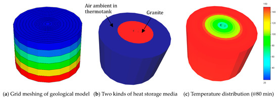
Figure 5.
The 3D numerical model of the self-circulation wellbore for heat mining.
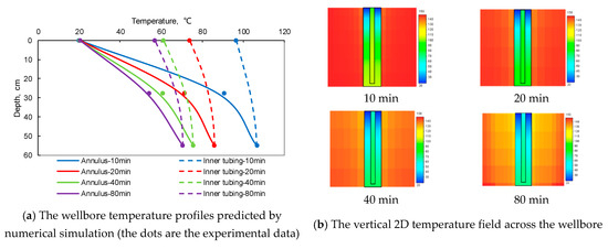
Figure 6.
Temperature distributions in the wellbore at different times.
It can be seen from Figure 6 that the heat mined by low-temperature water mainly comes from the hot rocks through the inner wall of the casing. After heat mining for 10 min, along the casing annulus downwards, the temperature of water increases quickly from 20 °C at the inlet to 92.2 °C at the middle, and then rises slowly to 106.7 °C at the bottom. This is because that in the upper casing annulus, the temperature difference between the annulus and granite jacket is large. The fluid in the annulus can extract a large amount of heat from granite jacket. The fluid temperature increases greatly and reaches close to the temperature of granite jacket. As a result, when the fluid flows into the lower annulus, a small temperature difference between fluid and granite jacket only brings a small heat flux. The temperature increase of fluid in the annulus becomes slowly. This makes the slope variation in the annulus temperature occur in the depth range 40–55 cm. When the water returns to the outlet in the inner tubing, the heat loss into the annulus causes the temperature of water to reduce to 96.5 °C at the outlet. As more and more heat is produced, both of the temperature field around the wellbore in the granite jacket and the temperature profile along the wellbore decrease and reach steady state gradually. At the steady heat exchange state, the monitored temperature of the outer wall of the casing is about 10 °C higher than that of the water in the annulus. This temperature difference can also be reflected by the fitted temperature field across the wellbore, in which the temperature of the granite jacket is larger than the wellbore.
(4) Heat flux and thermo-physical properties along the wellbore
Based on the complete wellbore temperature profile, the heat fluxes along the wellbore at different times were calculated, as shown in Figure 7. It can be seen that the heat flux in the casing annulus decreases significantly along the flow direction. The heat flux in the upper annulus is much higher than that in the lower annulus, which indicates that more heat is extracted from the upper hot rock of granite jacket because of the large temperature difference between the injected cold water and the hot rock. However, the heat flux in the inner tubing represents the heat loss from the inner tubing to the casing annulus. It is much smaller than that in annulus, but gradually increases along the flow direction.
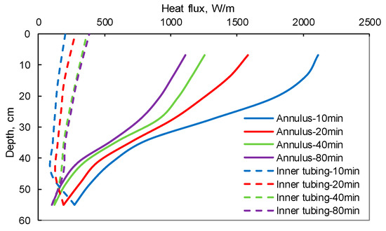
Figure 7.
Heat flux along the wellbore at different times.
The thermo-physical properties and the flow state of the water in the wellbore were also calculated. As shown in Figure 8a,b, the water density and viscosity decrease with the temperature increase in the casing annulus, and then increase with the temperature decrease in the inner tubing. As the heat mining proceeds with time, the density and viscosity of water in the wellbore also increase because of the overall decrease of wellbore temperature. The variation of the water density and viscosity will further affect the flow velocity and the Reynolds number in the wellbore. Figure 8c,d reveals that the flow velocity and the Reynolds number in the inner tubing are much larger than that in the casing annulus because of the small sectional area of the tubing for water flow. This design is very beneficial to the heat preservation in the inner tubing.
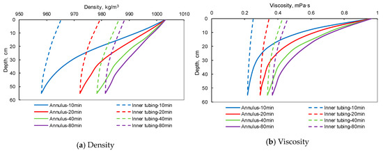
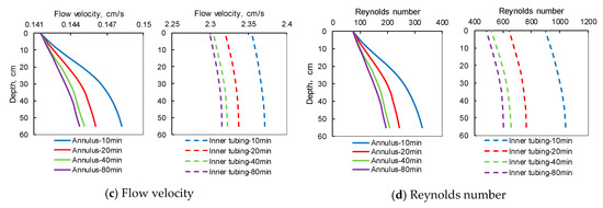
Figure 8.
Thermo-physical properties along the wellbore at different times.
3.2. The Influence of Various Factors on Wellbore Heat Exchange
3.2.1. Reservoir Type
Three heat storage media including granite jacket, quartz sand, and air ambient were selected to simulate different geothermal reservoirs for comparison. Under the basic conditions, the temperatures of the wellbore at different reservoir types are shown in Figure 9. The outlet temperatures are from laboratory experiments, while the wellbore temperature are values numerically predicted by fitting the temperature monitoring data. It can be seen that the temperature in the casing annulus increases greatly in the upper section, but the increase is small in the lower section because of the reduction of temperature difference between the casing annulus and the heat storage media. When the water flows upwards in the inner tubing, the temperature of water declines relatively small due to the small thermal conductivity of vacuum tubing. By comparison, the temperature along the wellbore and at the outlet of the heat exchange tube with granite jacket is much higher than that of quartz sand cylinder and air ambient. The granite jacket has the largest thermal conductivity and heat reserve as well as a middle heat capacity. The heat supply rate from the granite reservoir to the wellbore is large and fast. Hence, the granite jacket has the strongest heating ability to the wellbore, followed by the quartz sand, and the air ambient which has the worst heating capacity.
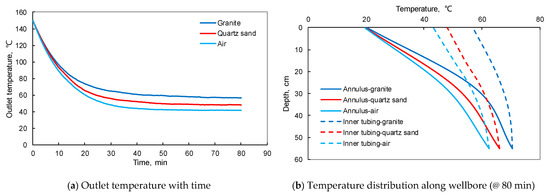
Figure 9.
Temperatures at the outlet and along the wellbore under different reservoir types.
The main heat exchange parameters under different reservoir types are shown in Figure 10. At the beginning of heat mining, the heat mined by water mainly comes from the stainless heat exchange tube, as a result, the heat mining rates in these three cases are close. When the heat exchange process in the wellbore reaches steady state (at 80 min), the heat mining rate in the case of granite jacket is 272 W, which is higher than the 211 W and 165 W in the cases of quartz sand and air, respectively. During this process, the heat stored in the granite jacket, quartz sand cylinder or ambient air is recovered, which is affected significantly by the heat capacity and the thermal conductivity of different reservoir types. Further, compared with the cases of quartz sand and air ambient, under the granite jacket condition, the heat flux in the casing annulus is the largest while the heat flux in the inner tubing is the smallest.
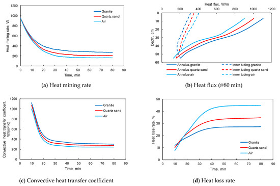
Figure 10.
The main heat exchange parameters under different reservoir types.
This indicates that more heat can be extracted from granite jacket, but smaller heat loss rate occurs in the inner tubing. As a result, the convective heat transfer coefficient of heat exchange tube obtained according to Equation (3) is also the largest because of the largest heat mining rate (Qw) when the granite jacket is used, and accordingly, referring to the Equation (6), the heat loss rate in the inner tubing is still the lowest because of the largest water temperature reached at the casing bottom. For the average convective heat transfer coefficients in the casing annulus in three reservoir types, they decrease rapidly at the beginning of heat mining but tend to be stable at last with a small difference. It can be seen that the influence of geothermal reservoir type on the convective heat transfer coefficient is little (245–301 W/(m2·K) at steady state), while the average convective heat transfer coefficient in the case of granite jacket is still the highest. For the heat loss in the inner tubing, as mentioned above, a higher wellbore temperature can lead to a lower heat loss rate because of the larger heat reserved and faster flow velocity of water. Hence, at the steady heat exchange state, when the granite jacket is applied, the heat loss rate in the inner tubing is 27.15% while in the air ambient, the heat loss rate is up to 45%.
3.2.2. Reservoir Temperature
Under the basic conditions, the temperatures of wellbore at different reservoir temperatures are shown in Figure 11. As the reservoir temperature increases from 60 °C to 180 °C (three times), the stable outlet temperature of the heat exchange tube increases from 30.9 °C to 64.9 °C (about two times), while the heat mining rate can increase from 84 W to 332 W (four times). Both of the outlet temperature and the heat mining rate increase linearly with the reservoir temperature increase. The temperature of the water in the inner tubing will be reduced by 4.8–16.1 °C due to the heat loss to the casing annulus.
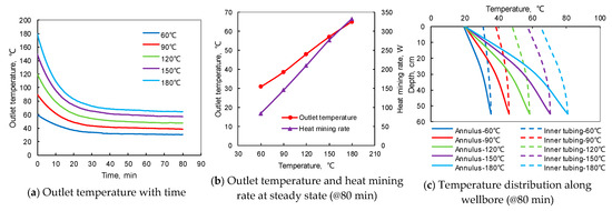
Figure 11.
Temperatures at the outlet and along the wellbore under different reservoir temperatures.
As shown in Figure 12, when the reservoir temperature increases three times, the heat mining rate of the water can increase nearly four times, which indicates that the reservoir temperature has a significant effect on the heat mining rate. At a higher reservoir temperature, the heat flux along the annulus is larger, but declines more sharply while the heat loss rate in the inner tubing is almost the same (26.9–27.8%). For the average convective heat transfer coefficient in the casing annulus, it is more different in the early 10 min, but after 80 min of heat mining, it tends to 260–347 W/(m2·K) at different reservoir temperatures. The reservoir temperature has a slight influence on the heat transfer coefficient.
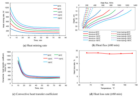
Figure 12.
The main heat exchange parameters under different reservoir temperatures.
In addition, the higher the reservoir temperature is, the more drastic the variation of density and viscosity of the water in the wellbore will be. When the temperature increases from 60 °C to 180 °C, the water flow velocity in the tube can increase by 2.3% while the Reynolds number can increase by 2.2 times, which is conducive to enhancing the convective heat transfer intensity in the casing annulus.
3.2.3. Inlet Pressure of Water
Under the basic conditions, the effect of inlet pressure on the wellbore temperature is shown in Figure 13. Inlet pressures at 5, 10, 15 MPa were tested, and the outlet temperatures at the stable stage are 55.9, 56.4 and 55.7 °C, respectively. The temperatures along the wellbore at different pressures are nearly the same, which indicates that the inlet pressure nearly has no effect on the heat transfer in the self-circulation wellbore. Due to the little compressibility of water, the density, viscosity, heat capacity, and the thermal conductivity coefficient of the water change little at different pressures.
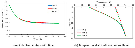
Figure 13.
Temperatures at the outlet and along the wellbore under different pressures.
3.2.4. Injection Rate of Water
Based on the basic conditions, the effect of injection rate on the wellbore temperature is shown in Figure 14. It can be seen that the higher the injection rate of water, the lower the outlet temperature. When the water rate increases from 27 mL/min to 533 mL/min, the outlet temperature decreases from 61 °C to 45.9 °C while the heat mining rate increases significantly with the increase of the injection rate. The outlet temperature decreases rapidly at the early stage of heat mining. The larger the rate is, the faster the outlet temperature decreases. In the first 10 min, the outlet temperature decreases from 150 °C to 99.5 °C at the water rate of 27 mL/min, while the outlet temperature decreases from 150 °C to 68.8 °C at the water rate of 533 mL/min. After heat mining for 80 min, the temperature at the outlet and along the wellbore tends to be stable.
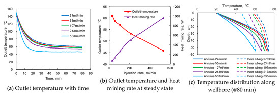
Figure 14.
Temperatures at the outlet and along the wellbore at different injection rates.
Figure 15 shows that with the increase of the injection rate, the heat mining rate of water increases (although the outlet temperature decreases as shown in Figure 14a).
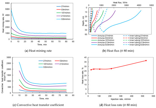
Figure 15.
The main heat exchange parameters at different injection rates.
When the heat exchange in the wellbore reaches steady state, the heat mining rate of water is only 75 W when the rate is 27 mL/min, while the heat mining rate can reach 960 W if the water rate is increased to 533 mL/min. Increasing the heat mining rate is at the cost of decreasing the outlet temperature, hence, the balance between a higher outlet temperature and a higher heat mining rate should be selected carefully according to specific requirements in field applications. Besides, the injection rate also has a great effect on the heat flux along the wellbore. A large injection rate means a large heat flux in the casing annulus extracted from the geothermal reservoir, accordingly, as well as a large heat flux in the inner tubing lost to the casing annulus. The convective heat transfer coefficient in the annulus, it increases remarkably from 87 to 807 W/(m2·K) with the increase of injection rate and Reynolds number. For the heat loss rate in the inner tubing, it maintains stable when the water rate is less than 213 mL/min, but starts to increase gradually as the water rate increases from 213 to 533 mL/min. As the Reynolds number of water flow in the tubing increases with the rate increase, the laminar flow is gradually converted to turbulent flow. The change of the water flow state in the inner tubing enhances the convective heat transfer to the annulus, so the heat loss rate from the inner tubing to the annulus is increased when the water rate is large enough. However, it should be noted that due to the limited size of the granite jacket, the air ambient will heat the granite jacket when the temperature drop front in the granite jacket reaches to the boundary. Under the experimental conditions, the thermal conductivity coefficients of air and granite are 0.035 W/(m·K) and 3 W/(m·K), respectively. According to Equation (7), the thermal resistance of the air ambient is 8 K/W, much larger than the 0.05 K/W of granite jacket. As a result, the heat mining rate at the late stage is much lower than the initial level. It can be seen that the time when the heat mining rate reached steady state (Figure 15a) is close to the time monitored when the temperature drop front reached the boundary of granite jacket, as shown in Figure 16 (the temperature sensor was attached on the top of the outer wall of the granite jacket). With the injection rate increase, the time of temperature drop front reaching to the granite jacket boundary was reduced from 48 min to 18 min with an average movement speed increasing from 0.1442 cm/h/°C to 0.3846 cm/h/°C, and the boundary temperature at steady state declined from 148 °C to 134 °C:
where, Rcon is the thermal resistance of heat storage media, K/W; δ is the effective thickness of the heat storage media in the radial direction, m, 0.28 m and 0.15 m were respectively for air ambient and granite jacket; λ is the thermal conductivity of the material, W/(m·K).
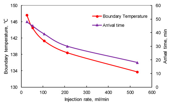
Figure 16.
The time of temperature drop front arriving at the granite jacket boundary and the stable boundary temperature at different injection rates.
3.2.5. Thermal Conductivity of the Inner Tubing
The thermal conductivity of the inner tubing can be modified by filling the hollow wall with heat transfer oil, or sucking air out to reach vacuum, or using a solid tube wall. Based on the basic conditions, the influence of the inner tubing thermal conductivity on the wellbore temperature is shown in Figure 17. As shown in Figure 17a,b, when the tubing wall is under vacuum, filled with heat-transfer oil, or solid, the outlet temperature of the heat exchange tube at steady state is 56.9 °C, 54.8 °C, and 50.1 °C respectively. Similarly, the temperature along the inner tubing is the highest in the case of the vacuum tubing wall. Due to the hollow wall, the thermal conductivity of the tubing will change, so the equivalent effective thermal conductivities of the inner tubing wall (λteff, W/(m·K)) under different tubing conditions were calculated according to the experimental data [20]. The formula used is as follows:
where ΔTt is the average temperature difference between the inner and outer walls of the tubing, °C, because the temperature of the tubing wall cannot be measured directly, for convenience, it is estimated according to 1/3 of the water temperature difference between the tubing and the casing annulus; Lt is the length of the inner tubing, m; the explanation of other parameters is as above.
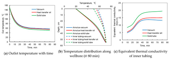
Figure 17.
Temperatures at the outlet and along the wellbore at different thermal conductivities of inner tubing.
As shown in Figure 17c, the calculated λteff increases first and tends to be stable later with time. In the initial stage, the λteff is small due to the little heat loss and the large ΔTt. When the outlet temperature reaches steady state, the λteff corresponding to the three kinds of insulation conditions are 13.5, 15, and 20.4 W/(m·K), respectively. The vacuum tubing has the lowest effective thermal conductivity.
The main heat exchange parameters under different tubing conditions are shown in Figure 18. As the λteff increases from 13.5 to 20.4 W/(m·K), the heat mining rate decreases by 18.75% from 274 to 223 W, while both of the heat fluxes in the casing annulus and the inner tubing are increased, indicating more heat lost to the annulus from the inner tubing.
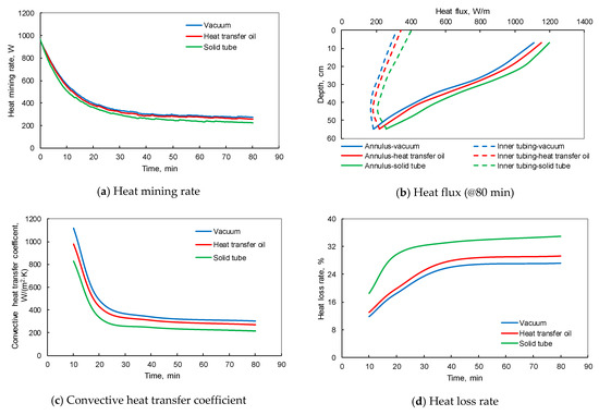
Figure 18.
The main heat exchange parameters at different thermal conductivities of inner tubing.
3.3. Estimation of Heat Mining Rate on the Field-Scale by Similarity Analysis
To estimate the heat-mining rate of the self-circulation wellbore on a field scale, a similarity analysis was conducted based on the experimental results. Generally, the pipe flow similarity should meet the geometric dimensioning similarity, flow state similarity, and the heat exchange similarity [27]. In the forced convection heat transfer, there are three independent similarity criteria, namely Nusselt number Nu, Reynolds number Re, and Prandtl number Pr. Nu represents the degree of convective heat transfer intensity, Re determines the flow state of fluid, and Pr reflects the influence of fluid physical properties on the convective heat transfer process. According to the second theorem of similarity, the solution of forced convection heat transfer equation can be expressed as the relationship between these three similarity criteria (Equation (9)). Hence, Nu was selected as the major similarity parameter.
According to the basic definition, Nu is the ratio of convective heat transfer flux to heat conduction flux through a fluid layer with a characteristic length of . It can be expressed as follows:
where is the convective heat transfer coefficient, W/(m2∙K); is the characteristic length, m, for the circular annulus section, the characteristic length = − , m; is the thermal conductivity of heat transfer fluid, W/(m·K).
In addition, for the heat transfer of laminar flow in the tube, the Nu can also be calculated by the Sieder-Tate correlation:
where is the Reynolds number in the tube, ; is the Prandtl number, ; d is the tube diameter, m; L is the tube length, m; ρ is the fluid density, kg/m3; is the average flow velocity of the fluid in the tube, m/s, in the casing annulus, , of which V is the volumetric fluid rate, m3/s, dto is the outer diameter of the tubing, m; c is the fluid heat capacity, J/(kg·K); is the dynamic viscosity of fluid, .
In the laboratory experiments, the initial temperature of heat exchange tube and heat storage media is uniform, and the vertical geothermal gradient is not considered. This working condition is very similar to the horizontal wellbore in field which has a constant ambient temperature. Therefore, the heat mining rate in a horizontal wellbore on a field scale can be estimated by similarity analysis based on the experimental results. The self-circulation wellbore has two opposite-direction flow channels with the casing annulus as the main channel extracting the heat from hot rocks. Hence, for convenience, the similarity of the casing annulus in a horizontal self-circulation wellbore was considered assuming that the inner tubing is totally adiabatic and the reservoir temperature around the wellbore is constant (If the heat loss from the inner tubing is considered, the estimated heat mining rate will be reduced by 5–10% on a field scale [11,16]). According to the similarity principle, the subscripts 1 and 2 are defined to stand for the laboratory scale and the field scale respectively, and the subscript w stands for the water, hence, the Nu1 in the casing annulus on the laboratory scale should equal to the Nu2 in the casing annulus on the field scale, namely = . According to Equations (10) and (11), the following two equations can be obtained:
By substituting the equation of the average velocity of the fluid (see the parameter explanation of Equation (11)) in the casing annulus into Equation (12), the following Equation (14) can be obtained:
By substituting Equations (2) and (3) into Equation (13), the Equation (15) can be obtained:
where, Vw1 is the injection rate on the laboratory scale, mL/min; Vw2 is the injection rate on the field scale, m3/day; ΔTm2 is the average heat transfer temperature difference between the heat transmission fluid and the casing wall on the field scale, °C; Qw2 is the heat mining rate on the field scale, W.
To calculate the heat mining rate on a field scale, a 2000 m horizontal well section with a casing inner diameter of 0.158 m and a tubing outer diameter of 0.114 m was assumed, as shown in Table 4. ΔTm2 (field scale) was assumed to be two times of the ΔTm1 (laboratory scale) by referring to the Wang’s numerical calculation results, in which similar reservoir and wellbore conditions were assumed [28]. The calculated heat mining rates on the field scale are shown in Table 5 and Figure 19.
Table 4.
Wellbore size and reservoir temperature on the laboratory and field-scale.
Table 5.
The estimated heat mining rate in a 2000 m horizontal well section.
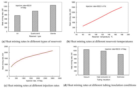
Figure 19.
The calculated heat mining rate of water in a 2000 m horizontal well section at different conditions.
As shown in Table 5 and Figure 19, when the injection rate increases from 27 mL/min to 533 mL/min on the laboratory scale, accordingly, on the field scale, the injection rate will increase from 152 m3/day to 3002 m3/day, and the heat mining rate will increase from 789 kW to 2141 kW. When the injection rate is 602 m3/day, as the reservoir temperature increases from 60 °C to 180 °C, the heat mining rate can increase from 391 kW to 1509 kW. For the reservoirs of granite, quartz sand, and air as the heat storage media, the heat mining rates can be 1252 kW, 973 kW and 761 kW, respectively (at 602 m3/day and 150 °C). And when the tubing wall is vacuum, filled with heat transfer oil, or solid, the heat mining rates in granite reservoirs can be 1252, 1181 and 1017 kW, respectively. In the field operation, insulated tubing can be used. It is often used in steam injection in thermal recovery of heavy oil. The thermal conductivity of tubing is as low as about 0.03 W/m/°C, which can reduce the heat loss greatly. Overall, the estimated heat mining rate of a 2000 m horizontal well section is the same order of magnitude as the predicted results of Wang et al. and Cui et al. under the similar geothermal reservoir and wellbore conditions (e.g. 1 MW @ (345 m3/day + 150 °C) – 1.9 MW @ (602 m3/day + 225 °C) in a 2000 m horizontal wellbore), which can prove the reasonability of the results of the similarity analysis [11,16,28].
The thermal short-circuiting phenomena are notable in such a short tube. Hence, it is necessary to select the tubing with an excellent insulation performance to reduce the heat loss, the effect of thermal short-circuiting in the wellbore can be eliminated. In addition, when the heat mining reaches steady state, the convective heat transfer coefficients in the casing annulus are 301, 268, and 216 W/(m2·K), and the heat loss rates in the inner tubing are 27.1%, 29.3%, and 35%, respectively for the vacuum tubing, tubing filled with heat transfer oil and solid tubing. Under the solid tube wall, the inner tubing has the strongest heat loss, while the casing annulus has the weakest heat mining capacity from the granite. The performance of vacuum wall is opposite to the solid wall.
4. Conclusions
The experimental results indicate that the reservoir type, reservoir temperature, injection rate and the insulation of the inner tubing have a significant influence on the heat exchange law and the heat mining rate of the self-circulation wellbore. The large thermal conductivity and heat capacity of granite jacket can cause a large outlet temperature and heat mining rate, and more heat can be extracted from granite but less heat is lost in the inner tubing; The reservoir temperature has a great effect on the heat mining rate, the heat mining rate can increase four times when the reservoir temperature increases three times; comparatively, the pressure in wellbore nearly has no effect on the heat exchange law in the wellbore; Injection rate has a great impact on the outlet temperature and the heat mining rate, a balance between the heat mining rate and the outlet temperature should be optimized according to the field requirement (because as the heat mining rate increases, the outlet temperature usually decreases); The inner tubing with a low thermal conductivity can significantly reduce the heat loss to the casing annulus, hence, the vacuum insulated tubing is recommended.
In addition, it should be noted that due to the small size of the built self-circulation wellbore, the heat stored in the heat exchange tubes and the boundary of the heat storage media have an influence on the heat exchange process in the wellbore, including the thermal short-circuiting in the wellbore, and the short time of the temperature drop front reaching the boundary. The former can make a large heat loss rate in the inner tubing, while the later can cause a low heat mining rate at the steady state. However, the calculation of heat mining rate on the field scale through similarity analysis can extend the values of the experimental results. The similarity analysis indicates that in the basic case, a 2000 m long horizontal well can contribute a heat mining rate up to 1.25 MW from a typical hot dry rock of 150 °C with a water circulation rate of 602.8 m3/day. This result is close to the published data at the similar working conditions, which can prove the reasonability of the results of the similarity analysis.
Author Contributions
Conceptualization, L.Z.; methodology, L.Z.; software, S.G.; validation, J.K..; formal analysis, J.K.; investigation, J.C.; resources, L.Z.; data curation, L.Y.; writing—original draft preparation, J.K.; writing—review and editing, F.Y.; visualization, J.C.; supervision, L.Z.; project administration, L.Z.; funding acquisition, L.Z. All authors have read and agreed to the published version of the manuscript.
Funding
This research was funded by the Fundamental Research Funds for the Central Universities, Ministry of Education, grant number 18CX05009A.
Acknowledgments
This research is supported by the Fundamental Research Funds for the Central Universities (No.), and partially financed by the National Major S&T Project (No. 2016ZX05056004-003) and the Program for Changjiang Scholars and Innovative Research Team in University (No. IRT 14R58). We also appreciate the reviewers and editors for their constructive comments to make the paper high quality.
Conflicts of Interest
The authors declare no conflict of interest.
References
- Lu, S.M. A global review of enhanced geothermal system (EGS). Renew. Sustain. Energy. Rev. 2018, 82, 2902–2921. [Google Scholar] [CrossRef]
- Tester, J.W.; Anderson, B.J.; Batchelor, A.S.; Blackwell, D.D.; DiPippo, R.; Drake, E.M.; Garnish, J.; Livesay, B.; Moore, M.C.; Nichols, K.; et al. The future of geothermal energy: Impact of enhanced geothermal systems (EGS) on the United States in the 21st century. In Proceedings of the Thirty-Second Workshop on Geothermal Reservoir Engineering, Stanford, CA, USA, 2–4 January 2006. [Google Scholar]
- Haraden, J. The status of hot dry rock as an energy source. Energy 1992, 17, 777–786. [Google Scholar] [CrossRef]
- Wang, G.L.; Zhang, W.; Ma, F.; Lin, W.J.; Liang, J.Y.; Zhu, X. Overview on hydrothermal and hot dry rock researches in China. China Geol. 2018, 1, 273–285. [Google Scholar] [CrossRef]
- Zhang, L.; Ezekiel, J.; Li, D.; Pei, J.; Ren, S. Potential Assessment of CO2 Injection for Heat Mining and Geological Storage in Geothermal Reservoirs of China. Appl. Energy 2014, 122, 237–246. [Google Scholar] [CrossRef]
- Kumari, W.G.P.; Ranjith, P.G.; Perera, M.S.A.; Li, X.; Li, L.H.; Chen, B.K.; Isaka, B.A.; De Silva, V.R.S. Hydraulic fracturing under high temperature and pressure conditions with micro CT applications: Geothermal energy from hot dry rocks. Fuel 2018, 230, 138–154. [Google Scholar] [CrossRef]
- Lu, C.; Wang, G.L. Current status and the prospect of hot dry rock research. Sci. Technol. Rev. 2015, 33, 13–21. [Google Scholar]
- Liao, Z.; Wan, T.; Zhang, Z. The enhanced geothermal system (EGS): Huge capacity and difficult exploitation. Earth Sci. Front. 2015, 22, 335–344. [Google Scholar]
- Kujawa, T.; Nowak, W.; Stachel, A.A. Utilization of existing deep geological wells for acquisitions of geothermal energy. Energy 2006, 31, 650–664. [Google Scholar] [CrossRef]
- Bu, X.; Ma, W.; Li, H. Geothermal energy production utilizing abandoned oil and gas wells. Renew. Energy 2011, 41, 80–85. [Google Scholar] [CrossRef]
- Cui, G.; Ren, S.; Zhang, L.; Ezekiel, J.; Enechukwu, C.; Wang, Y.; Zhang, R. Geothermal exploitation from hot dry rocks via recycling heat transmission fluid in a horizontal well. Energy 2017, 128, 366–377. [Google Scholar] [CrossRef]
- Holmberg, H.; Acuña, J.; Næss, E.; Sønju, O.K. Thermal evaluation of coaxial deep borehole heat exchangers. Renew. Energy 2016, 97, 65–76. [Google Scholar] [CrossRef]
- Song, X.; Zheng, R.; Li, G.; Shi, Y.; Wang, G.; Li, J. Heat extraction performance of a downhole coaxial heat exchanger geothermal system by considering fluid flow in the reservoir. Geothermics 2018, 76, 190–200. [Google Scholar] [CrossRef]
- Nian, Y.L.; Cheng, W.L. Evaluation of geothermal heating from abandoned oil wells. Energy 2018, 142, 592–607. [Google Scholar] [CrossRef]
- Cheng, W.L.; Liu, J.; Nian, Y.L.; Wang, C.L. Enhancing geothermal power generation from abandoned oil wells with thermal reservoirs. Energy 2016, 109, 537–545. [Google Scholar] [CrossRef]
- Wang, Y.; Zhang, L.; Cui, G.; Kang, J.; Ren, S. Geothermal development and power generation by circulating water and isobutane via a closed-loop horizontal well from hot dry rocks. Renew. Energy 2019, 136, 909–922. [Google Scholar] [CrossRef]
- Cheng, W.L.; Li, T.; Nian, Y.L.; Wang, C.L. Studies on geothermal power generation using abandoned oil wells. Energy 2013, 59, 248–254. [Google Scholar] [CrossRef]
- Beier, R.A.; Acuña, J.; Mogensen, P.; Palm, B. Borehole resistance and vertical temperature profiles in coaxial borehole heat exchangers. Appl. Energy 2013, 102, 665–675. [Google Scholar] [CrossRef]
- Beier, R.A.; Acuña, J.; Mogensen, P.; Palm, B. Transient heat transfer in a coaxial borehole heat exchanger. Geothermics 2014, 51, 470–482. [Google Scholar] [CrossRef]
- Gordon, D.; Bolisetti, T.; Ting, D.S.; Reitsma, S. Experimental and analytical investigation on pipe sizes for a coaxial borehole heat exchanger. Renew. Energy 2018, 115, 946–953. [Google Scholar] [CrossRef]
- McDaniel, A.; Tinjum, J.; Hart, D.J.; Lin, Y.F.; Stumpf, A.; Thomas, L. Distributed thermal response test to analyze thermal properties in heterogeneous lithology. Geothermics 2018, 76, 116–124. [Google Scholar] [CrossRef]
- Dai, C.; Li, J.; Shi, Y.; Zeng, L.; Lei, H. An experiment on heat extraction from a deep geothermal well using a downhole coaxial open loop design. Appl. Energy 2019, 252, 11347. [Google Scholar] [CrossRef]
- Zhang, F.Z.; Jiang, P.X.; Xu, R.N. System thermodynamic performance comparison of CO2-EGS and water-EGS systems. Appl. Therm. Eng. 2013, 61, 236–244. [Google Scholar] [CrossRef]
- Cui, G.; Zhang, L.; Ren, S. Assessment of heat mining rate for geothermal exploitation from depleted high-temperature gas reservoirs via recycling supercritical CO2. Energy Procedia 2017, 105, 875–880. [Google Scholar] [CrossRef]
- Zhang, J.Z.; Chang, H.P. Heat Transfer; Science Press: Beijing, China, 2015. [Google Scholar]
- Zanchini, E.; Lazzari, S.; Priarone, A. Effects of flow direction and thermal short-circuiting on the performance of small coaxial ground heat exchangers. Renew. Energy 2010, 35, 1255–1265. [Google Scholar] [CrossRef]
- Peng, Y.L.; Li, W.X.; Wei, K.J.; Xie, H.; Wang, Y. Principle and verification of a similar experiment system for vertical ground heat exchangers. Heat. Vent. Air Cond. 2018, 48, 45–49. [Google Scholar]
- Wang, Y. Geothermal Exploitation via Circulating Fluid within a Closed-Loop Horizontal Well from Hot Dry Rocks. Master’s Thesis, China University of Petroleum (East China), Qingdao, China, 2019; pp. 29–31. [Google Scholar]
© 2020 by the authors. Licensee MDPI, Basel, Switzerland. This article is an open access article distributed under the terms and conditions of the Creative Commons Attribution (CC BY) license (http://creativecommons.org/licenses/by/4.0/).