1. Introduction
Electric vehicles (EVs) are nowadays commercially available by several makers worldwide. A large amount of electric power can be stored in lithium-ion batteries of EVs. The stored electric power can be injected into the utility-grid; this is named as vehicle-to-grid (V2G). A domestic consumer can consume the stored electric energy, where the lithium-ion batteries in an EV perform as a peak shaver; this is called vehicle-to-home (V2H). These interesting concepts were proposed in [
1,
2,
3,
4,
5,
6]. A bidirectional battery charger (BBC) using three-leg-structured isolated-gate bipolar transistors (IGBTs), which consists of a single-phase two-leg pulse-width-modulated (PWM) rectifier and a bidirectional DC-DC converter, is used in V2G and V2H. In [
7], the vehicle-to-vehicle (V2V) concept was proposed in addition to V2G and V2H. It is well known that the reactive and harmonic currents can be controlled independently of the fundamental active currents on the source side [
8]. Therefore, reactive power compensation strategy was included in the control circuit of the single-phase two-leg PWM rectifier in the BBC to control the source-side terminal voltage at the point of common coupling in single-phase two-wire distribution feeders [
9,
10,
11,
12]. For three-phase circuits, G. Buja et al. dealt with reactive power compensation capabilities with V2G [
13].
Single-phase three-wire distribution feeders are used for domestic consumers in Japan. When the two-leg PWM rectifier with reactive power control is used to control the source-side terminal voltage at the point of common coupling in single-phase three-wire distribution feeders, unbalanced source-side current conditions remain. The present authors proposed a BBC with a power quality compensator for EVs, which was applicable to a domestic consumer in single-phase three-wire distribution feeders [
14]. The previously proposed BBC comprises four-leg-structured IGBTs. Two legs connect each feeder, while one leg connects a neutral line. Connecting one leg to the neutral line can compensate the unbalanced components in single-phase three-wire distribution feeders. The fourth leg is used as a bidirectional DC-DC converter. This bidirectional DC-DC converter charges or discharges the lithium-ion batteries in EVs. A constant DC-capacitor voltage control (CDCVC)-based strategy was used for the control algorithm of the three-leg PWM rectifier in the previously proposed BBC. Simulation and experimental results demonstrated that the three-leg PWM rectifier in the previously proposed BBC achieved the balanced source currents at a unity power factor. Diode rectifiers with large-capacity smoothing capacitors are widely used in consumer electronics nowadays. These diode rectifiers, however, generate a large amount of harmonic currents and inject them into utility-grid. Therefore, the authors dealt with power quality compensation of the CDCVC-based control algorithm for the previously proposed BBC [
15]. Simulation and experimental results demonstrated that the balanced and sinusoidal source currents at a unity power factor were obtained in the domestic consumers, which are connected to single-phase three-wire distribution feeders. Works in literature [
14,
15] demonstrated that the CDCVC-based strategy for the three-leg PWM rectifier in the BBC can compensate not only the fundamental reactive and unbalanced active components but also harmonic components on the source side of the domestic consumers in single-phase three-wire distribution feeders. However, the source-side terminal voltages at the point of common coupling in single-phase three-wire distribution feeders were sinusoidal. It is also known that the diode rectifier with the large-capacity smoothing capacitor produces flat-top voltage waveforms at the point of common coupling in single-phase distribution feeders [
16]. These flat-top voltage waveforms are typical in single-phase distribution feeders. The definition of the flat-top voltage waveform is described in detail [
17]. According to the IEEE Standard 519-2014 [
18], the maximum total harmonic distortion (THD) value of the voltage at the point of common coupling is determined to be 5.0%, and the ratios of each individual-order harmonics to the fundamental component should be less than 3.0% if the bus voltage is from 1 kVrms to 69 kVrms. Therefore, not only distorted load-current but also distorted source-voltage with the flat-top voltage waveforms should be taken into account if the previously proposed BBC is connected to actual domestic consumers in single-phase three-wire distribution feeders. In [
15], the load-side currents in a domestic consumer were distorted while the source-side voltage was sinusoidal. This means that only the fundamental active power is included in the load currents. The fundamental active power also exists on the source side, before or after compensating the power quality on the source side by the three-leg PWM rectifier in the BBC. This demonstrates that the source-side fundamental active power equals the load-side fundamental active power. However, the harmonic active power in addition to the fundamental active power exists on the load side when both the terminal voltages at the point of common coupling and load currents in a domestic consumer are distorted. Only the fundamental active power exists on the source side after compensating the power quality in the domestic consumer by the three-leg PWM rectifier in the BBC. Therefore, balancing of the source-side active power with the load-side active power by CDCVC-based strategy for the three-leg PWM rectifier in the BBC should be demonstrated.
This paper deals with power quality compensation in single-phase three-wire distribution feeders using the CDCVC-based strategy of the previously proposed BBC for electric vehicles under the distorted source-voltage and load-current conditions. Instantaneous active power flowing into the three-leg PWM rectifier in the BBC is discussed. The instantaneous power flowing into the three-leg PWM rectifier demonstrates that the CDCVC-based strategy obtains balanced and sinusoidal source currents at a unity power factor, where the source-side fundamental active power is balanced with the load-side active power, which consists of the harmonic active power in addition to the fundamental active power. Simulation and experimental results demonstrate that balanced and sinusoidal source currents at a unity power factor are attained in single-phase three-wire distribution feeders with both battery-charging and -discharging operations for electric vehicles even though both source voltage and load currents are distorted.
2. Power Quality Compensation in Single-Phase Three-Wire Distribution Feeders with CDCVC-Based Strategy of BBC under Distorted Source-Voltage and Load-Current Conditions
Figure 1 shows a circuit diagram of the previously proposed BBC in single-phase three-wire distribution feeders, where both secondary-side voltages
and
and load currents
and
are distorted. Many consumer electronics nowadays contain diode rectifiers. Thus, diode rectifiers are connected to both feeders. The THD values of the load currents
and
were determined considering IEC61000-3-4 [
19]. By the IEEE Standard 519-2014, the maximum THD value of the voltage at the point of common coupling is determined to be 5.0%, and the ratios of each individual-order harmonics to the fundamental component should be less than 3.0% when the bus voltage is from 1 kVrms to 69 kVrms [
18]. In
Figure 1, the primary-side voltage of the distribution transformer is 6.6 kVrms. Thus, the primary-side voltage distortion is decided according to the IEEE Standard 519-2014. The third-order harmonic voltage of 2.7%, fifth-order harmonic voltage of 2.0%, and seventh-order harmonic voltage of 1.2% are included in the primary-side voltage
in
Figure 1. Considering these harmonic voltages in the primary-side voltage
, the flat-top voltage waveforms at the point of common coupling are achieved. The THD value of the source voltage
on the primary-side is 3.6%. The BBCs for EVs, for which the source-side power quality can be improved, were proposed for V2G and V2H concepts [
9,
10,
11]. The proposed BBCs comprise a two-leg-structured PWM rectifier with a bidirectional DC-DC converter. However, the proposed BBCs for EVs with power quality compensation proposed in [
9,
10,
11] are not applicable to single-phase three-wire distribution feeders. A three-leg PWM rectifier is used in
Figure 1. Connecting the third-leg
and
to the neutral line can compensate the unbalanced components in single-phase three-wire distribution feeders.
Table 1 shows test data for the single-phase distribution transformer used in
Figure 1 on PSIM software.
For the control algorithm of active power-line conditioners in three-phase circuits, the instantaneous active–reactive power theory, which was originally proposed by Prof. Akagi et al., is widely used [
8]. A single-phase p-q theory was also proposed for an active power-line conditioner in single-phase circuits [
20]. Calculation blocks for the reactive, unbalanced-active, and harmonic components are required in the control circuits of the active power-line conditioners with those theories. The CDCVC block is also included in addition to the calculation blocks for the unbalanced active, reactive, and harmonic components. In
Figure 1 however, only the CDCVC block is used for the control strategy of the three-leg PWM rectifier in the BBC. This CDCVC-based strategy attains balanced and sinusoidal source currents at a unity power factor. The secondary-side voltage
is detected. The electrical angle
that is synchronized with
is then generated by the single-phase phase-locked loop (PLL) [
21,
22]. Note that the single-phase PLL proposed in [
21,
22] can generate the angular frequency
, which is perfectly synchronized with the fundamental component of
, under the heavily distorted source-voltage conditions. The DC-capacitor voltage
of the three-leg PWM rectifier is detected, and then the difference
between the reference value
and the detected
is amplified by the Proportional–Integral–Differential (PID) controller. A moving-average low-pass filter (MALPF) is used to remove the 2
components, where
is the angular frequency of
. After the MALPF, the root-mean-square (RMS) value 2
of the source currents
and
is calculated. The reference active component
is calculated by multiplying
with
, where
. The reference values
and
for the three-leg PWM rectifier are expressed as
A current controller for a single-phase PWM rectifier with Proportional–Integral (PI) controllers in
d-
q coordinates was proposed to suppress a steady-state error [
23]. The proposed current controllers for the single-phase three-leg PWM rectifier are used to control the output currents
,
, and
. In single-phase circuits, the third-order harmonic currents exist. The third-order harmonic currents affected the THD values of the source currents
and
in [
15]. The present authors proposed the addition of a current controller for third-order harmonic currents with a PI controller in
d-
q coordinates to suppress these third-order harmonic components in the source currents [
24]. The added current controllers suppress the third-order harmonics on the source side. In this paper, the switching frequency
is 9.36 kHz. The number of data points over the cycle of the fundamental frequency is 156. The number of data points for the quarter-cycle-delay block of the fundamental component is 39. The number of data points for the quarter-cycle-delay block of the third-order harmonics is 13. The current controllers in
d-
q coordinates for the third-order harmonics are perfectly synchronized with
.
The fourth leg, and , acts as a bidirectional DC-DC converter. During the battery-charging operation, the fourth leg acts a buck chopper, where controls the inductor current while is off and only the diode in is used. For the battery-discharging operation, the fourth leg acts a boost chopper, where controls while is off and the diode in is used. In both the buck and boost operations, is detected. The difference between the reference value and is amplified by a PI controller; subsequently, with the triangle intersection method, the control signal for or is generated to control the inductor current . As a battery model, an ideal DC voltage source of 360 Vdc with an inner resistor r of 72 m in PSIM software is also used because the purpose of this paper is to demonstrate harmonic currents compensation with the CDCVC-based strategy of the previously proposed BBC for electric vehicles in single-phase three-wire distribution feeders under distorted load-currents and source-voltage conditions.
The instantaneous power flowing into the three-leg PWM rectifier in the BBC is now discussed under the distorted source-voltage and load-current conditions to demonstrate that the CDCVC-based strategy in
Figure 1 attains the balanced and sinusoidal source currents
and
at a unity power factor. In the literature [
24], the voltages
and
on the secondary side of the distribution transformer were sinusoidal.
and
were given by
As described before, the flat-top voltage waveforms are typical in single-phase distribution feeders. According to the IEEE Standard 519-2014, harmonic components are included in the source voltage
, shown in
Figure 1. When the source voltage
is distorted, the secondary-side voltages
and
are expressed as
The unbalanced and distorted load currents
and
in Feeder1 and Feeder2 are also expressed as
When the three-leg PWM rectifier in the BBC with CDCVC-based strategy attains the balanced and sinusoidal source currents at a unity power factor, the desired source current
, which is
and
, in Feeder1 and Feeder2 is expressed as
where
is the RMS value of
,
, and
. With (
5), the output currents
,
, and
of the three-leg PWM rectifier are given by
The instantaneous power
flowing into the three-leg PWM rectifier in the BBC is given by
The mean value
is given by
If the DC-capacitor voltage
is kept constant by the CDCVC-based strategy for the three-leg PWM rectifier in
Figure 1, the mean value of
should be the battery power
in (
7). The mean value
is expressed as
From (
8) and (
9), the RMS value
in (
5) is given by
Equation (
10) demonstrates that the CDCVC-based strategy for the three-leg PWM rectifier in
Figure 1 attains balanced and sinusoidal source currents at a unity power factor even though both source voltages and load currents are distorted. If the secondary-side voltages
and
are sinusoidal, as expressed by (
2) in [
24], the RMS value
in (
5) is expressed as
The RMS value
is originated in the fundamental active components on the load side with
. Note that the RMS value
in (
10) is increased with the harmonic components, which is
, as compared with
in (
11). This demonstrates theoretically that the source-side fundamental active power is balanced with the load-side active power, which consists of the harmonic active power in addition to the fundamental active power, by the CDCVC-based strategy in
Figure 1 and balances the active power between the source side and load side. However, the harmonic active components in (
10) are much smaller than the fundamental components in the following simulation and experimental setup because the third-order component of 2.7%, fifth-order component of 2.0%, and seventh-order component of 1.2% are included in the primary-side voltage
in
Figure 1. The BBC with the IGBTs also causes losses. Thus, balancing the active power between the source side and load side cannot be practically demonstrated. In the following simulation and experimental results, the active power balancing will not be demonstrated. It is also noted that the third-order, fifth-order, and seventh-order harmonics in the load currents
and
are increased by 2.7%, 2.0%, and 1.2% as compared with those of the load currents
and
in the literature [
15,
24]. This means that the load currents waveforms
and
in the following simulation and experimental results are similar to those in [
15,
24].
3. Simulation Results
The validity and high-practicability of the CDCVC-based harmonics compensation with the three-leg PWM rectifier in the BBC under distorted source-voltage and load-current conditions are confirmed by digital computer simulation using PSIM software. In single-phase three-wire distribution feeders, the unbalanced ratio (UR) is defined as
where
is the apparent power in Feeder1 and
is the apparent power in Feeder2.
is the sum of apparent powers
and
in Feeder1 and Feeder2, respectively. The maximum UR is determined by Japanese guidelines [
25]. According to the guidelines [
25], the UR should be less than 40% for domestic power consumption. A Load1 of 1.2 pu is connected in Feeder1, where the power factor is 0.87, and the THD value is 23.7% in
Figure 1. A Load2 of 0.8 pu is connected in Feeder2, where the power factor is 0.90, and the THD value is 20.9%. Generally, the load conditions in Feeder1 and Feeder fluctuated greatly. In [
26], the required-capacity of the three-leg PWM rectifier in the previously proposed BBC was discussed by digital computer simulation using PSIM software under several load conditions in Feeder1 and Feeder2. The simulation results demonstrated that the required-capacity of the three-leg PWM rectifier was maximum with Load1 of 1.2 pu and Load2 of 0.8 pu. This means that the amplitudes of the output currents
,
, and
are maximum with Load1 of 1.2 pu and Load2 of 0.8 pu. These load conditions are severe for the three-leg PWM rectifier. Thus, Load1 of 1.2 pu and Load2 of 0.8 pu are connected in Feeder1 and Feeder2 in the following simulation and experimental results.
Table 2 lists the circuit constants for
Figure 1, which are used in the following simulation results.
= 0.6,
= 30.0 ms, and
= 0.01 ms are used in the PID controller for the CDCVC. In PI controllers in
d-
q coordinates for both the fundamental and third-order currents,
= 0.06 and
= 8 ms are used.
= 0.15 and
= 3 ms are used in the PI controller for the current feedback control of the bidirectional DC-DC converter. These values in controllers are determined with Ziegler–Nichols ultimate sensitivity method and then improved with a digital computer simulation.
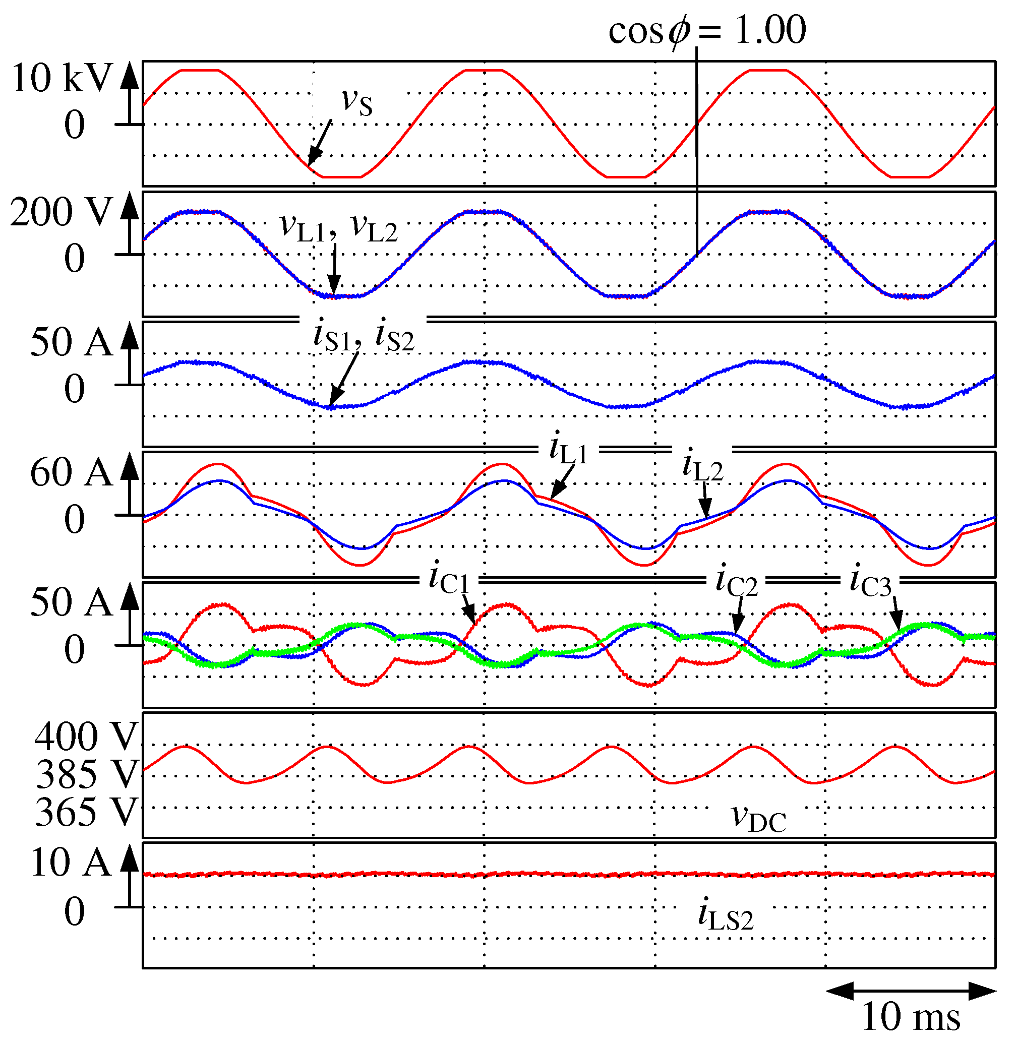
Figure 2 shows the simulation results for
Figure 1, where the proposed BBC charges the battery with the constant battery current control.
is the source voltage, and
and
are the secondary-side voltage waveforms;
and
are the secondary-side current waveforms;
and
are the load-side current waveforms of the domestic consumer.
,
, and
are the output current waveforms of the BBC;
is the DC-capacitor voltage waveform; and
is the switching inductor current waveform of the bidirectional DC-DC converter. The reference value
for
is −5 Adc, where the minus sign means that the bidirectional DC-DC converter charges the battery
. The switching inductor current
is well adjusted to the reference value
. The source currents
and
are balanced and sinusoidal at a unity power factor although the load currents
and
are unbalanced and heavily distorted, and the secondary-side voltages
and
are also distorted. The THD values of
and
are 2.0% and 1.9%, respectively, and the voltage ripple of
is 1.2%. The simulation results of
Figure 2 demonstrate that the proposed BBC of
Figure 1 improve the power quality on the source side in single-phase three-wire distribution feeders charging the battery
in EVs.
Figure 3 shows the simulation results for
Figure 1, where the proposed BBC discharges the battery with constant battery current control. The DC-DC converter discharges the battery
with the positive reference value
of 5 Adc. The switching inductor current
is also well controlled to the reference value
. The source currents
and
are also balanced and sinusoidal at a unity power factor. The THD values of
and
are 3.5% and 2.6%, respectively, and the voltage ripple of
is 1.2%. The simulation results of
Figure 3 also demonstrate that the proposed BBC of
Figure 1 improve the power quality on the source side in single-phase three-wire distribution feeders discharging the battery
in EVs.
When an owner drives an EV, the battery
is disconnected from the proposed BBC in
Figure 1. Both
and
in the bidirectional DC-DC converter are off. The proposed BBC in
Figure 1 acts as an active power-line conditioner in single-phase three-wire distribution feeders.
Figure 4 shows the simulation results for
Figure 1 without the battery
. The source currents
and
are balanced at a unity power factor. The THD values of
and
are 2.1% and 2.1%, respectively, and the voltage ripple of
is 1.2%. The THD values of
and
in
Figure 2,
Figure 3 and
Figure 4 satisfy the regulations [
19]. The proposed BBC can improve the power quality in single-phase three-wire distribution feeders even though the owner drives the EV.
Note that the THD values of
and
were worst during the battery-discharging operation because the amplitudes of
and
are minimized in the simulation results of
Figure 2,
Figure 3 and
Figure 4. In the literature [
15], the THD values of
and
were 12.6% and 9.8%, respectively, during the battery-discharging operation. The THD values of
and
are 3.5% and 2.6%, respectively, shown in
Figure 3. The simulation results of
Figure 2,
Figure 3 and
Figure 4 demonstrate that the addition of current controllers for third-order harmonics greatly improves the THD values of the source currents
and
in single-phase three-wire distribution feeders.
4. Experimental Results
In
Figure 1, the primary-side voltage is 6.6 kVrms. Thus, it is difficult to construct an experimental setup with the actual voltage rating of the distribution transformer for
Figure 1 in the laboratory. Instead, a reduced-scale experimental setup is constructed and tested to demonstrate the validity and high-applicability of the CDCVC-based strategy of the BBC for EVs in single-phase three-wire distribution feeders.
Figure 5 shows a block diagram of the constructed prototype experimental setup. The ratings of the distribution transformer are 180 Vrms, 3.7 kVA, and 60 Hz on the primary side and 90 Vrms and 20.6 Arms on the secondary side.
Table 3 shows test data for the distribution transformer in
Figure 5. A programmable AC power source (NF ES-2000 Series) is connected on the primary side of the reduced-scale distribution transformer. A crest factor (CF) is defined as
Controlling the CF with the NF ES-2000 Series power source achieves the distorted source voltage
. In
Figure 5, the CF is 1.33. The third-order component of 2.7%, fifth-order component of 2.0%, and seventh-order component of 1.2% are included in the primary-side voltage
in
Figure 5. The THD value of the primary-side voltage
is 3.6%. A Load1 of 1.2 pu is connected to Feeder1, where the power factor is 0.87 and the THD value is 23.8%. A Load2 of 0.8 pu is connected to Feeder2, where the power factor is 0.88, the THD value is 24.1%, and the UR given by (
12) is 40%. As shown in
Figure 5b, a resistor
R of 60
is connected in parallel to the DC-capacitor
during the battery-charging operation. The connected resistor
R consumes the charged power, which is from the utility-grid. During the battery-discharging operation, a DC power supply (Takasago: HX0300-25) with an internal resistance
r of 72 m
is connected to the DC-capacitor
, where the output voltage of the DC power supply is 257 Vdc because, as described before, the purpose of this paper is to demonstrate power quality compensation with the CDCVC-based strategy of the previously proposed BBC for electric vehicles in single-phase three-wire distribution feeders under distorted load-currents and source-voltage conditions.
Figure 6 shows a picture of the constructed experimental setup for
Figure 5. Using this experimental setup, the following experimental results are obtained. The circuit constants for
Figure 5, which are used in the following experimental results, are also shown in
Table 2.
The secondary-side voltage
, load currents
and
, output currents
and
, DC-capacitor voltage
, and inductor current
are detected. These detected values are then fed into a digital signal processor (DSP) (TMS320C6713, 225 MHz) through 12-bit A/D converters. The sampling time
is 0.107 ms. Thus, the switching frequency
is 9.36 kHz. This switching frequency achieves the current controllers in
d-
q coordinates for the third-order harmonic components, which is perfectly synchronized with
. The reference values
,
, and
for the three-leg PWM rectifier are calculated by (
1) in the DSP. The current controllers for both the fundamental and third-order harmonic currents are also carried out in the DSP. The circuit constants listed in
Table 2 are used in
Figure 5.
= 0.6,
= 0.03 s, and
= 0.01 ms are used in the PI controller for the CDCVC-based strategy.
= 0.06 and
= 8 ms are used in the PI controllers of the current feedback control in
d-
q coordinates.
= 0.15 and
= 3 ms are used in the PI controller of the current feedback control in the bidirectional DC-DC converter during both battery-charging and battery-discharging operations.
The YOKOGAWA SL1000 High-Speed Data Acquisition Unit was used in the experiments, shown in
Figure 6. The csv-formatted data is generated in the SL-1000 High-Speed Data Acquisition Unit. The following experimental waveforms were obtained importing the csv-formatted data to Excel.
Figure 7 shows the experimental results for
Figure 5 during the battery-charging operation with constant battery current control. The resistor
R of 60
consumes the charged power from the utility-grid, as shown in
Figure 5b.
is the source-voltage waveform, and
and
are the secondary-side-voltage waveforms;
and
are the secondary-side current waveforms;
and
are the load-side current waveforms of the domestic consumer;
,
, and
are the output current waveforms of the BBC;
is the DC-capacitor voltage waveform; and
is the switching inductor current waveform of the bidirectional DC-DC converter. As shown in
Table 2, the reference value
for
in the experimental setup is −4.29 Adc. As written in the simulation results, the minus sign means that the bidirectional DC-DC converter charges the battery
. Note that the charged power, which is from the utility-grid, is consumed by the resistance
R of 60
. The switching-inductor current
is well-adjusted to the reference value
. The source currents
and
are balanced and sinusoidal at a unity power factor, although the load currents
and
are unbalanced and heavily distorted and the secondary-side voltages
and
are distorted. The THD values of
and
are 4.1% and 3.1%, respectively, and the voltage ripple of
is 1.2%.
Figure 8 shows the experimental results for
Figure 5, where the proposed BBC discharges the power from the battery
, which is the DC power supply (Takasago: HX0300-25) with a constant battery current control, as shown in
Figure 5c. The reference value
for
in the experimental setup is 4.29 Adc. The switching-inductor current
is also well controlled to the reference value
. The source currents
and
are balanced and sinusoidal at a unity power factor. The THD values of
and
are 7.1% and 5.4%, respectively, and the voltage ripple of
is 1.7%. The experimental results of
Figure 7 and
Figure 8 demonstrate that the proposed BBC of
Figure 1 improve the power quality on the source side in single-phase three-wire distribution feeders charging or discharging the battery
in EVs.
Figure 9 shows the experimental results for
Figure 5, where both the resistor
R and DC power supply are not connected to the capacitor
, and where
and
in the bidirectional DC-DC converter are off. The proposed BBC performs as an active power-line conditioner in single-phase three-wire distribution feeders. The source currents
and
are balanced and sinusoidal at a unity power factor. The THD values of
and
are 5.3% and 4.1% respectively, and the voltage ripple of
is 1.8%. The experimental results of
Figure 9 also demonstrate that the proposed BBC of
Figure 1 can improve the power quality in single-phase three-wire distribution feeders even when the owner drives the EV.
The THD values of
and
were 17.0% and 10.2% during the battery-discharging operation in the literature [
15], while the THD values of
and
are 7.1% and 5.4%, respectively. The experimental results of
Figure 7,
Figure 8 and
Figure 9 also demonstrate that the addition of current controllers for third-order harmonics greatly improves the THD values of the source currents
and
in
Figure 1. The experimental results of
Figure 7,
Figure 8 and
Figure 9 well agree with the simulation results of
Figure 2,
Figure 3 and
Figure 4, respectively. This demonstrates that the experimental results of
Figure 7,
Figure 8 and
Figure 9 with the reduced-scale experimental setup of
Figure 5 are valid.

 ,
, 


