Abstract
The production of ammonia, consuming up to 5% of natural gas global production, accounts for about 2% of world energy. Worldwide, the Haber–Bosch process is the mainly used method of ammonia catalytic synthesis, involving temperatures up to 600 °C and pressures up to 32 MPa. In this paper, the results of the development and study of the special welded construction of plate heat exchanger (WPHE) for a column of ammonia synthesis are presented. The heat transfer and hydraulic performance of developed WPHE are investigated on a one-pass model in laboratory conditions. An equation for the relation between heat transfer effectiveness and the number of heat transfer units is proposed. A mathematical model of multi-pass WPHE is developed using these results. The validity of this model is confirmed by results of industrial tests performed with the prototype WPHE installed in operating column of ammonia synthesis at temperatures about 500 °C and pressure about 32 MPa. The tests confirmed the reliability of WPHE and its efficiency compared to a tubular heat exchanger. A method of optimal design of WPHE that allows finding the optimal height of corrugations and the number of passes in WPHE for specified conditions of operation is developed.
1. Introduction
The sustainable development of modern society requires the efficient energy usage to limit the depletion of fossil fuels resources and minimise the environmental hazard of their combustion, which is leading to the generation of harmful emissions and, especially, CO2 and greenhouse gases. It is the most important for industries with high levels of energy involved in production processes. One of such processes is the synthesis of such valuable product as ammonia, which is widely used in different industrial applications, such as the production of fertilisers, fibres, polymers and plastics, papers, acids and explosive materials [1]. It is also can be used as a carbon emission-free carrier of hydrogen, offering a high energy density that could be used in a system for energy transport, storage and power generation [2].
Up to 72% of industrial ammonia production worldwide is based on the steam reforming of methane from natural gas [3]. It is mainly performed using the Haber–Bosch process, requiring gaseous nitrogen from air and hydrogen. Their mixture is forming syngas that is moving through the catalyst at temperatures up to 600 °C and pressures up to 32 MPa. The synthesis reaction is exothermic, with the generation of large amounts of heat energy that have to be removed with a good cooling system. This industrial process is responsible for consumption up to 5% of natural gas global production, accounting for nearly 2% of the world’s energy generation and emitting about 1% of greenhouse gases [4].
The practical industrial realisation of this process is performed mostly with reactors of three different types: reactors with direct internal cooling, reactors of adiabatic quench cooling and indirect adiabatic cooling. [5] reports a comparison of these reactor cooling systems, showing the advantage in the efficiency of the internal direct cooling system. An exergy approach for modelling and optimisation of an industrial ammonia synthesis unit was presented in [6]. It was concluded that the biggest part of exergy destruction is happening in the ammonia reactor. The exergy study of two concepts in ammonia synthesis loop configurations is presented in [7]. It includes an adiabatic reactor with three stages including intermediate quench cooling and indirect-cooled reactor. It is concluded that the major equipment (reactor, heat exchangers) must be accounted for first for improvement of the overall design with consideration for the implementation of heat integration.
In recent years, to reduce fossil fuel usage and the impacts on the environment of conventional ammonia production, green processes of ammonia production with the use of green hydrogen have been investigated. The comparative study of such production schemes, presented in [8], has shown the importance of maximising the heat recovery of the overall system that requires efficient heat exchangers. The use of ammonia synthesis combined with nitrogen production and power generation is discussed in [9]. The uses of solar energy in ammonia production and optimisation for energy, cost and carbon emission are studied in [10]. The thermochemical storage systems of solar energy based on ammonia are investigated in [11]. The efficient and compact recuperative heat exchangers are needed to increase heat recuperation and save energy in all these processes involving ammonia synthesis. The principles of heat transfer intensification are the major tool in developing the construction of such heat exchangers [12].
Plate Heat Exchangers (PHEs) are one of the high-efficiency types of compact heat exchangers with intensified heat transfer. The main construction features and principles of operation and design for PHE have been well discussed in publications (see, e.g., [13]). The most known is plate-and-frame PHE, which was initially developed and used in food production and later confirmed its efficiency in many different applications. It is proved in many research results; for example, in [14] it was shown that, for water to water heat transfer, plate-and-frame PHE has about a 13% lower cost than a tubular heat exchanger at the same position. The high efficiency of PHE is confirmed at the chemical industry [15], in the process of the CO2 capture [16], for waste heat utilisation from exhaust gas [17]. However, the range of operating conditions for plate-and-frame PHE is limited by pressure below 25 bar and a temperature not more than 180 °C, mostly by the presence of elastomeric gaskets. For severe working conditions with aggressive fluids, the cost of gaskets from sophisticated elastomers can substantially increase the cost of the whole PHE.
To increase the field of PHE applications in different industries by limiting the use of elastomeric gaskets, constructions of the brazed (BPHE) and welded (WPHE) types of PHE were developed. In WPHE, the sealing of passages between plates is made by welding, allowing an increase of the working temperatures and pressures significantly. Currently, different types of WPHE are developed and fabricated by PHE producers. The most frequently used are Plate-and-Block (Compabloc) PHE and Plate-and-Shell HE (PSHE), compared in [18]. Now, WPHEs finding their way in many applications, e.g., more than 750 Compabloc heat exchangers were installed at different positions in the oil refining industry [19]. The welded construction allows an increase in working temperatures below 400 °C and pressure up to 42 bar.
The main feature of Compabloc WPHE is the use of crossflow of streams in one pass and the overall counter-flow arrangement in a whole heat exchanger. Such a construction feature is also used in WPHE, specially developed for operation inside the shell of the column for ammonia synthesis at temperatures up to 525 °C and pressures about 320 bar [13] (pp. 79–80). It consists of round, corrugated plates, like the one shown in Figure 1. The plates are produced with different diameters to fit the columns, with inside diameters from 600 to 1200 mm. In the manufacturing process, plates are collected and welded together to form criss-cross flow channels with multiple contact points at the edges of corrugations. It makes a robust construction capable of withstanding high-pressure difference between heat-exchanging streams. The created round block of welded plates is equipped with welded collectors and baffles that are organising the multi-pass flow of heat exchanging streams through the channels systems. There is a crossflow of streams in an individual pass with globally countercurrent flow arrangement in WPHE as a whole. From the point of flow distribution in a channel and the pressure drop in it, such an arrangement has an advantage compared to plate-and-frame PHE where the flow is distributed from a relatively small port to the full width of the channel. It involves additional pressure loss in that distribution zone that can be avoided with crossflow of streams in one pass of considered WPHE. However, the crossflow can involve a considerable reduction in the effective mean temperature difference between streams, and the deterioration of heat transfer effectiveness, the overall countercurrent flow in multi-pass WPHE is organised to limit this effect. However, the influence of crossflow in individual passes has to be considered accurate enough for an engineering applications design of WPHE.
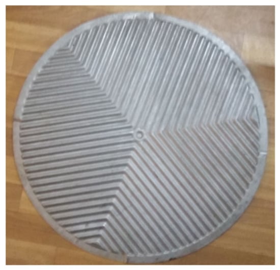
Figure 1.
The plate of WPHE for an ammonia synthesis column.
The convenient way to account for crossflow in a heat exchanger is the use of the relationship between effectiveness, ε, of heat transfer and the number NTU of heat transfer units. Equations of such a relationship for idealised flow models of both fluids—mixed and unmixed—and one fluid mixed, and another unmixed, are presented in the book [20]. But in real heat exchangers, such a relationship can differ significantly, depending on the heat exchanger type and the level of flows mixing in its channels. This phenomenon was investigated by a number of researchers. The case of two unmixed fluids with the development of approximate equation for it was studied by Triboix [21]. For compact heat exchangers with different and complex finned surfaces, a hybrid method was proposed in [22]. The survey of recent developments on heat transfer in crossflow tubular and tubes-and-fins heat exchangers is presented in [23]. For crossflow tubular heat exchangers with different tube passes, closed-form relationships of temperature effectiveness are proposed by Magazoni et al. [24]. The results of the study of multi-row cross flow tubes-and-fins heat exchangers are reported in [25] and approach to calculate overall heat transfer coefficient for water–air tubes-and-fins heat exchanger in [26]. The results of the parametric study of cross flow heat exchangers with heat transfer enhancement by external and internal recycles were reported by Luo [27]. For compact diffusion-bonded crossflow heat exchangers, the results of theoretical and experimental study of heat transfer were reported in [28], with further development in [29]. In their study of the cabinet cooling system, Borjigin et al. [30] have found that, at certain conditions with crossflow PHE, the system has lower thermal resistance and better cooling performance with counter-flow PHE.
Presently, there are very few published data accurate enough to perform design and optimisation of the considered WPHE type for the engineering applications. The correlations obtained for counter-flow PHEs need to be validated and adopted for the considered type of channels with the crossflow and variable angle of corrugations on the surface of forming round channel plates. There are no data allowing adequate estimations of the level of fluid mixing in PHE channels for the use of published relations for the crossflow correction factor, depending on the level of fluids mixing in channels.
The aim of the present paper is to develop a method of modelling and optimisation, which considers WPHE for an ammonia synthesis column with round plates that is accurate enough for engineering applications. It is based on mathematical modelling and experimental data on heat transfer and pressure drop in WPHE channels. Reported here are the results of an experimental study, in laboratory conditions, of the thermal and hydraulic performance of a one-pass crossflow model of WPHE for ammonia synthesis column. On that basis, the mathematical model of multi-pass WPHE is developed, and its validation in industry performed. After that, the use of the model for optimisation of WPHE for specific conditions of its operation is described.
2. Laboratory Experiment
For the accurate modelling and design of WPHE, the reliable correlations for a calculation of heat transfer and pressure drop in channels of specific geometry are required. Such correlations for the models of criss-cross flow channels of PHEs with countercurrent flow are presented in [31], and the approach for their application for commercial plates in [13] (pp. 228–231). To check the validity of these correlations and to adopt them for specific construction of developed WPHE with crossflow of streams, the experimental data are needed.
The experimental study of heat transfer and pressure losses is performed with the model of WPHE having 15 plates welded together for modelling one pass of WPHE. There are 14 channels formed between plates; seven channels are for the hot stream, and the other seven channels are for the cold stream. The geometries of the channels at the hot and cold sides are different. At the cold stream, the side channel is formed by two plates, assembled in WPHE, which have different corrugation angles to the main flow direction. On one plate, corrugations are mainly (at 2/3 of plates area) situated parallel to the main flow. The corrugations on the other plate are inclined with the angle of 60° to the direction of the main flow. The average corrugation angle in this part of the channel is 30°. In the other third of the channel area, the angle of corrugations on both plates forming the channel is 60°. The averaged channel area angle of corrugations is β2 = 40°. The averaged on another channel area angle of corrugations to the main flow direction in this channel is β1 = 50°. These forms of corrugations at channel walls are made for facilitating the removal of possible dust in a stream, leaving a catalyser that can start to appear with catalyser aging. The geometrical parameters of the WPHE model, its plates and channels, are given in Table 1.

Table 1.
The parameters of WPHE experimental model.
The thermal and hydraulic parameters of the WPHE model are determined from measurements at the test rig with distilled water flowing as hot and cold fluids. The structure of the test rig is shown in Figure 2. It has a closed water circuit. The water is pumped from its reservoir to the shell-and-tube steam heater to maintain specified temperature t11 of the hot stream at the model inlet. Inside the WPHE model it is being cooled to a temperature t12 at the outlet, and afterwards, it is directed to the additional PHE for cooling to temperature t21 by cold water from the centralised circuit with the cooling tower. With this temperature cold stream entering the WPHE model, it is heated to the cold stream outlet temperature t22 and is coming back into the water reservoir. The circulating water flowrate is measured with orifice meter. The temperatures at the entrances and exits of heat exchanging streams in the WPHE model are measured with an accuracy of ±0.05 °C by thermocouples copper–constantan. Two differential pressure gauges are used to measure pressure drops of hot- and cold-water streams. The tests are performed in a stable regime. The water temperature after the steam heater was varied from 55 to 85 °C. The temperature of cold water in the reservoir was in the range of 30 to 45 °C. The flowrate of circulating water was in the range of 0.8 and 4.5 kg/s.
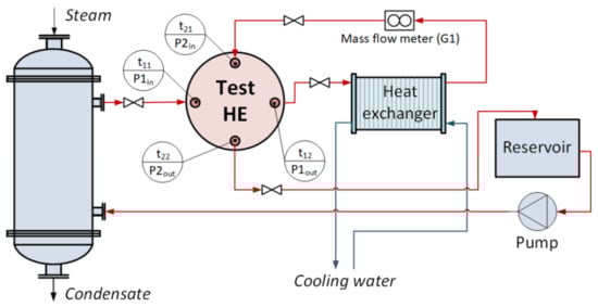
Figure 2.
Structure of the test rig.
The heat load Q of the model is determined as an average of the calculated for cold stream Q2 and for hot stream Q1, W:
where G is mass flowrate of water, kg/s; cp1 is the specific heat capacity of a hot stream, J/(kg·K); cp2 is the specific heat capacity of a cold stream, J/(kg·K).
In a closed water circuit, the mass flowrates of hot and cold streams are the same, and the heat capacity difference is less 0.3%, so heat capacity flowrates are equal, and the mean temperature difference is
The experimental value of overall heat transfer coefficient, W/(m2·K), is as follows:
The experimental results are compared with calculated by Equation (4):
where hi are the film heat transfer coefficients for cold (index i = 2) and hot (index i = 1) sides, W/(m2·K); λw is a thermal conductivity of plate metal, W/(m·K); δw thickness of the plate metal, m; Rf is the fouling thermal resistance in WPHE, m2·K/W. In laboratory experiments, it is taken that Rf = 0.
The film heat transfer coefficients are calculated based on the modified analogy of heat and momentum transfer [31]:
where µi is fluid dynamic viscosity at the main flow temperature, Pa∙s; μwi is fluid dynamic viscosity at the wall temperature, Pa∙s; Nu = hi⋅de/λi is Nusselt number; λi is fluid thermal conductivity, W/(m·K); Pri is Prandtl number; ζi is the friction factor; ψi is the ratio of friction pressure loss to a total loss of pressure; FX is the factor of area enlargement because of corrugations.
The value of ψi is calculated by Equation proposed in [32]:
For calculation of friction factor, Equation (7) is used [31]:
where p1i, p2i, p3i, p4i, p5i are the parameters depending on the corrugation geometry:
γi = 2⋅b/S is double height to pitch ratio of corrugation; βi is the angle of corrugation to the main flow direction, degrees; Rei = wi⋅de⋅ρi/µi is Reynolds number; wi is the flow velocity, m/s; de = 2⋅b is the channel equivalent diameter, m; µi is fluid dynamic viscosity, Pa∙s; ρi is the fluid density, kg/m3.
The experimental and calculated values of overall heat transfer coefficients at different cold-water velocities in channels are compared. The calculated results are higher than experimental ones, with deviations up to +8%. The explanation is in a reduction of real average temperature difference compared to that calculated by Equation (2) because of the crossflow. The heat transfer effectiveness of the WPHE model is as follows:
Effectiveness dependence from the number of heat transfer units (NTU) is presented in Figure 3. NTU is determined using calculated value Ucl of overall heat transfer coefficient by Equation (9):
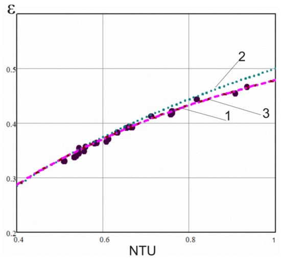
Figure 3.
The relation ε-NTU for WPHE model: 1—experiment; 2—counter- current; 3—calculated by Equation (10) for crossflow in WPHE for the ammonia synthesis column.
The heat transfer effectiveness, ε, experimental values are smaller than calculated by Equation for countercurrent flow (curve 2 in Figure 3). It is better approximated by the Equation presented in [20] for cross flow and stream, with a higher corrugation angle β1 = 50°, mixed, and another with lower corrugation angle β1 = 40°, unmixed. For a better approximation, the corrected factor 0.97 is added:
where R is the ratio of heat capacities flowrates:
Equation (10) is suitable for the calculation of one pass effectiveness when calculating multi-pass WPHE by the ε-NTU method described by Arsenyeva et al. [33].
Besides thermal efficiency, the hydraulic performance of the WPHE is of primary importance for its correct design. The experimental results on Euler number Eui = ΔPi/(ρi·wi2) for streams are presented in Figure 4.
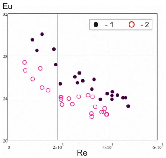
Figure 4.
The experimental data for pressure losses: 1—hot stream; 2—cold stream.
For the channel with a bigger corrugation angle β1 = 50°, the pressure losses are higher than for another channel of β2 = 40°. Following the approach proposed in [34] for the estimation of pressure drop in plate-and-frame PHE at the main corrugation field and channel distribution zones at the entrance and exit separately, the total pressure drop at the stream in multi-pass WPHE can be summarised as follows:
where winx.i is the velocity at channel entrance/exit, m/s; ζDzi is the coefficient of local hydraulic resistance in entrance/exit zones; Xi is a number of passes.
By comparison of the calculation by Equation (12) with the ζi determined by Equation (7), the coefficients of local hydraulic resistance in the channels’ distribution zones were obtained: ζDZ1 = 11, ζDZ2 = 17. The error of estimation by Equation (12)—the experimentally measured pressure drop in channels—does not exceed ±8%, as illustrated in Figure 5.

Figure 5.
The comparison of experimental pressure drop calculated by Equation (12): 1—hot stream; 2—cold stream.
3. Mathematical Modelling
The reliable and accurate mathematical model of a heat exchanger is the base for the development of its design and optimisation of construction elements. The task of modelling WPHE thermal performance for its rating consists in finding its total effectiveness of heat transfer in WPHE εT for the specified NTU, a value which is determined by a given WPHE construction and stream flowrates by Equation (9) in the assumption that thermo-physical properties in the calculation of heat transfer coefficients are taken for streams’ average temperatures. For any pass’s arrangement, the general method in the matrix form proposed for Compabloc WPHE in [18] can be used. But for the construction features of a considered WPHE for ammonia synthesis column, the number of pass combinations is limited. The bigger number of passes for one streamside has to be an integer multiple of the smaller passes number for another streamside or X1 = X2 × k, where k is an integer. An example of flow arrangements for a smaller number of passes, n = 4, is presented in Figure 6a for passes 4 × 4 and 8 × 4. For such conditions, a simplified mathematical model can be used based on Equation (13) proposed for total effectiveness εT at equal passes arrangement with an overall countercurrent flow [35]. It is made considering the stream, with smaller pass numbers, n blocks of plates, with a flow arrangement of 1 × k and a heat transfer effectiveness, εx, of individual blocks for R ≠ 1:
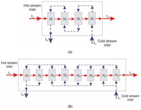
Figure 6.
The schematic flow arrangements in 4 × 4 WPHE (a) and in 8 × 4 WPHE (b).
For the special case, when R = 1, to avoid uncertainty, it is calculated as:
For the symmetric arrangement of passes, when the passes numbers are equal X1 = X2 = n for both streams in WPHE, such a block of plates is a symmetric one-pass heat exchanger with heat transfer area Fa/n. Its heat transfer effectiveness, εx, is equal to the effectiveness of one-pass heat exchanger, ε0, calculated in the following Equation (10) as:
where NTU0s number in the symmetric block of plates is equal to NTU/n.
With unsymmetrical passes arrangements (see Figure 6b), one block consists of two sub-blocks of plates. For the cold side, there is one pass, and for the hot side, two sub-passes—as for k = 2—is shown in Figure 6b. For the last pass on the cold stream (first from the left in Figure 6b), the temperature drops of hot stream in the first sub-block is δt11 and, in the second, δt12:
where Δ = t11 − t24 is the difference of temperatures at streams incoming into considered sub-blocks; R02 = R/2 is the ratio of heat capacities flowrates in sub-blocks of plates; ε02 is heat transfer effectiveness of the sub-block of plates which consist from 1/8 of the plates total number. The individual effectiveness of all sub-blocks is assumed the same, as all have the same heat transfer area and streams flowrates. The effectiveness of one block of plates consisting of two sub-blocks:
The heat transfer effectiveness of one sub-block, ε02, is determined by Equation (10) with NTU in one sub-block NTU02 = NTU/8, assuming its equal distribution in all WPHE and the ratio of heat capacities flowrates is R02. By substitution of X1 = 2X2 received from Equation (18) into Equation (13), the total heat transfer effectiveness of WPHE is obtained for the case of unsymmetrical passes arrangement X1 = 2·X2. The other values of k in relation X1 = k·X2 are not presenting practical interest and not considered in this paper. When the heat transfer effectiveness of WPHE εT is found, the outlet temperatures can be calculated, as well as heat load and all other parameters required for WPHE thermal modelling.
The calculation of pressure drop in the hydraulic design of WPHE is made by Equation (12) for each of the streams.
4. Industrial Tests
The validation of the developed mathematical model is checked using the results of industrial tests of prototype WPHE installed in high-pressure column operating at an ammonia production unit. The column structure is presented in Figure 7. The reactor catalyser box (3) with connected WPHE (1) is placed inside the shell (4) which diameter is 800 mm. The shell is designed for a temperature up to 525 °C to accommodate working pressure up to 32 MPa. The incoming syngas is fed from the top and flowing down inside the annular gap between the shell and equipment inside it reaching inlet of WPHE at temperature t21. In WPHE syngas is heated to temperature t25 by the stream of gas after the reactor. Syngas leaving the WPHE is mixing with bypass gas that is supplied at the column bottom having temperature tb1. It is going through special channels at the WPHE sides. It is coming next by the central pipe (5) to the top of the catalyser box (3) and then into internal (9) and external (7) field tubes. It is heated there and after coming directly to contact with catalyser (8). Leaving catalyser zone (6) through a header (2), a gas of temperature t11 is supplied to WPHE for cooling down to temperature t19 and going out from the bottom of the column.
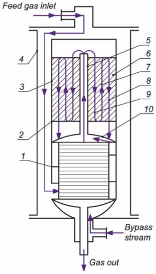
Figure 7.
The schematic structure of the column for ammonia synthesis: 1—WPHE; 2—header; 3—catalyser box; 4—high pressure shell; 5—central pipe; 6—catalyser zone; 7—external field tubes; 8—catalyser; 9—internal field tubes; 10—upper cover.
The main parameters of tested WPHE are presented in Table 2. The flow of streams in it arranged, as shown in Figure 6b with eight passes on the hot side and four passes on the cold side. The measurements of temperatures of streams coming in and out of the WPHE were performed with chromel–alumel thermocouples. For the entering of thermocouples into a column, the special high-pressure nozzle was installed. The flowrates of supplied syngas and bypass were measured by orifice flow meters. High-pressure gauges are used for measurement of gas pressures at its entrance and exit from the column.
Table 2.
Parameters of tested WPHE.
The data of the four tests are given in Table 3. There are also presented results of modelling of WPHE performance. The experimental values of heat transfer effectiveness are calculated by Equation (8). These values are in good agreement with calculated using Equations (13), (15) and (18) of the developed mathematical model. The accuracy of the developed mathematical model can be considered as sufficient for practical applications. It can be used for the design of this type of WPHEs. The calculation of pressure drop in WPHE is performed using Equation (12), and results are also presented in Table 3. The total pressure drop on both streams is not exceeding 100 kPa, within the limits of technical requirements; however, to compare it with test data accurately is not possible, as measured results include all the ways in which gases pass through the column, including the catalyser zone that takes the biggest part of total pressure losses. The comparison with data obtained before with the tubular heat exchanger has not revealed any differences in pressure losses.
Table 3.
The results of WPHE tests in the industry.
Before the column renovation, a tubular heat exchanger with a length of 3 m, heat transfer area of 148 m2 and weight of 2992 kg was installed. The weight of WPHE is 1694 kg, occupying a volume of 0.96 m3, that compared to tubular, is only 0.48 m3 smaller. In the remaining spare volume, an additional catalyser was added with proper modernisation of a catalyser box. It leads to a 15% increase in ammonia output.
The heat transfer effectiveness, εT, is reduced compared to its value for a pure countercurrent flow arrangement from 14.6% to 17.2%. This reduction in effectiveness is caused by the asymmetrical arrangement of passes. The conclusion is that, with the crossflow in individual passes, the symmetric arrangement of passes in WPHE is preferable. The detailed analysis of this problem is made with an optimisation approach to WPHE design presented in the next sections.
5. Optimal Design of WPHE for Ammonia Synthesis Column
The mathematical model presented Section 3, validated in industrial conditions, can be used for the calculation of the optimal parameters of WPHE construction, as well as for WPHE optimal design based on plates of specific geometry. Here, the problem of WPHE optimisation consisting of finding the best construction parameters satisfying specified process conditions on heat transfer and pressure drop performance is considered. An approach discussed in [36] is used. The objective function is the heat transfer surface area of WPHE. There are a number of constraints that must be satisfied:
- (i)
- The diameter of the plate must be equal to the value that allows installing WPHE inside a high-pressure shell of the column with specified internal diameter (equality constraint);
- (ii)
- The geometry of plate corrugations is chosen experimentally from the same type of investigation, with differences only in the corrugation’s height;
- (iii)
- The heat transfer effectiveness εT is not lower than specified εTS;
- (iv)
- The pressure drop is not higher than the allowable value;
- (v)
- The symmetric flow arrangements only are considered X1 = X2 = n. The optimising variables are the integer number of streams passes n and plates corrugations height b.
The estimation of the heat transfer performance of the WPHE is done through the determination of heat transfer effectiveness εT. The total effectiveness of the heat exchanger with symmetric passes and countercurrent flow is determined by Equation (13) with the ratio of heat capacities flowrates R calculated by Equation (11). The value of effectiveness in one-pass εx, required to satisfy the effectiveness of the whole WPHE, can be derived from Equation (13) as follows:
The number of transfer units in one block of plates corresponding to one pass of crossflow WPHE from Equation (15):
It is required for fulfilment by WPHE of specified thermal process conditions. The number NTUx that can be obtained in one block of WPHE plates corresponding to one pass is according to the heat transfer ability of the block:
where Fax is the heat transfer area of the block of plates, m2.
Expressing Fax through the number of plates in one block and G2 through the number of channels and flow velocity in channel w2 and channel cross-section area it is obtained:
where Fpl is the heat transfer area of one plate, m2; ρ2 is the density of the cold fluid, kg/m3; fch = W∙b is the channel cross-section area, m2; W is the width of the channel, m.
The plate heat transfer surface area:
For the WPHE of ammonia synthesis column, the length of the plate Lpl is equal to its width W and, from Equation (22), when the thermal constraint (iii) is completely satisfied (NTUx = NTU0x), Equation (24) follows:
Following the approach of [36], let us determine the plate length for the condition that pressure drop of the hot stream is strictly satisfied. From Equation (12), when the pressure drop ΔP1 is equal to the allowable pressure drop ΔP10,
The flows velocities at the cold side (w2) and hot side (w1) are linked by Equation (26):
When the hydraulic conditions by Equation (25) and thermal conditions by Equation (24) are satisfied simultaneously, the right sides of Equations (25) and (24) are equal. Accounting for Equation (26) for velocity in the hot channel, Equation (27) follows:
The variables ς and U at the right side of Equation (27) are the nonlinear functions of velocity w1 expressed by Equations (4)–(7). The solution of Equation (27) gives the value of w1 at which constraints (iii) and (iv) are satisfied as equalities and a corresponding value of overall heat transfer coefficient U is estimated. As a result, the value of WPHE heat transfer area for WPHE with n passes:
The relations determining this objective function include nonlinear Equations and integer variable number of passes n. Besides, the numbers of plates and channels are also integers. To find the optimum of such function is the problem of Mixed-Integer Nonlinear Programming (MINLP). The numbers of plates and channels have rather big values and, on the first stage of finding the solution, can be treated as continues variables. The Equation (27) is a recurrent relation relative to velocity w1. Its solution by iterations gives the value of the velocity of a hot stream that, for a plate with specified geometrical parameters, strictly satisfies the thermal conditions and allowable pressure drop at the hot stream in a one-pass block of plates. When this velocity is obtained, the required plate length Lpl can be calculated by Equations (24) or (25). In case of a correct solution for w1, both are giving the same results. To satisfy the constraint (i), this plate length must be equal to the value specified for a given diameter of the column. The problem is solved by finding local optimums of plate spacing bopt.i at which constraint (i) for plate length is satisfied as equality. It is made for the series of increasing pass numbers n, starting from 2. The calculations are finished when bopt.i begin to increase. The value of bopt.i corresponding to a minimum of objective function Fa and corresponding it passes number n are regarded as an optimal solution. After that, the number of plates in one block is rounded up, and rating design of WPHE performed. The method is implemented as a software for PC. The time of calculations for different conditions have not exceeded 200 s. The process of finding a solution is illustrated in the following case study.
6. Case Study
The ammonia synthesis column with diameter 0.8 m is considered. The limiting WPHE plate diameter to fit in this column is 0.6 m, corresponding to an effective plate length of Lpl = 0.54 m. The operating conditions required by the process are given in Table 4. In the process of design, the height of corrugations b was changed from 0.3 to 0.5 mm and, correspondingly, the cross-section area of the channel, fch. It is done for consecutive numbers of passes n in the heat exchanger. The fixed design parameters are given in Table 5. The average angle of corrugation is β1 = 40° for the hot side and β2 = 50° for the cold side. The coefficients ζDZ1 = 11 for the hot side, and ζDZ2 = 17 for the cold side are taken according to laboratory tests. The design is made for bypass 20% on the cold stream to enable process control with the aging of the catalyser.
Table 4.
The required operating conditions for case study.
Table 5.
The fixed values in the WPHE optimal design.
Attempts to calculate one-pass WPHE have shown that, at given temperatures, programming one-pass WPHE is not feasible at any increase of heat transfer area. The calculations with not fixed Lpl for different pass numbers show the existence of local optimums with certain minimal values of WPHE heat transfer in area F. That value is lower for a smaller number of passes. However, for its fulfilment, an unacceptable plate length can be required; e.g., for a two-pass WPHE with a corrugation height of 3 mm, the minimal heat transfer area is 95 m2 and required plate length 0.9 m. In this case, the loss of mean temperature difference due to crossflow is too big. The calculations for WPHE with a number of passes, n = 3 and higher, produce the heat transfer area from 64 to 90 m2 with smaller required plate lengths. However, there is also an adverse influence of crossflow in one pass that is more emphasised at smaller passes numbers. In these cases, WPHE construction features and imposed constraints must be accounted for.
As is discussed in [13] (pp. 54–65), for compact heat exchangers, the decrease of the equivalent diameter of channels leads to a smaller heat transfer area and improved compactness. However, then the problem of adjusting the plate length into its required limits arises. In the considered case, to fit into the high-pressure shell, the specified plate length is LplS = 0.54 m. The locally optimal value for the given passes number can be selected only if they fit values of corrugation height b at which Lpl = LplS. In the case under consideration, these values are b = 3.3 mm at n = 3 with F = 68.3 m2 (that is considered as global optimum) and b = 4.7 mm at n = 4 with F = 72.9 m2 that is shown in Figure 8. Line (1) in Figure 8 shows the minimal values of the heat transfer area that could be achieved without constraint for plate length. By line (2), there is also a designated heat transfer area that is needed to satisfy the required process conditions with inequality constraints for heat load Q° or pressure drop ΔP° at Lpl = 0.54 m. In that case, only one constraint is satisfied strictly, but another with some margin. At b, lower than the locally optimal value, the optimal plate length is smaller than LplS. The number of plates in WPHE and its heat transfer area must be increased to fulfil pressure drop requirement ΔP = ΔP° and WPHE can transfer more heat Q > Q°. At b, higher than the locally optimal value, the optimal plate length is bigger than LplS. The number of plates in WPHE and its heat transfer area has to also be increased to make it shorter, but to satisfy constraint strictly on the heat load, Q = Q°. With this, the pressure drop became smaller than required, ΔP ˂ ΔP°.
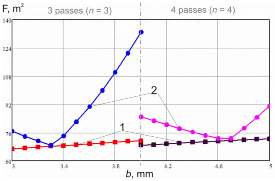
Figure 8.
The calculated results for the set of corrugations height b and symmetrical flow arrangement: line 1—the WPHE area for Lpl not fixed; line 2—the WPHE area for Lpl = 0.54 m.
When a designer has already manufactured plate, as the example in Figure 1 investigated here, the required number of plates in WPHE and heat transfer area can be estimated by calculations for specified corrugations height b = 4 mm. The results of such calculations are shown at graphs in Figure 8 for the number of passes n = 3 and for n = 4. For n = 3, the heat load is strictly satisfied at F = 132.94 m2 with pressure drop 4430 Pa, that on 82% lower than specified. For n = 4, strictly satisfied is a pressure drop at F = 85.12 m2 while heat load has 3.1% of margin. This second option is preferable not only for a smaller heat transfer area but also for better utilisation of pressure drop which is leading to high velocities and wall shear stress in channels that can mitigate possible fouling with catalyst dust. While this heat transfer area is on 24.6% bigger than an optimal global solution, it is 25.4% smaller than of prototype WPHE with unsymmetrical passes arrangement described above in Section 4. The heat transfer effectiveness with symmetrical passes arrangement n = 4 is 0.842 compared to 0.862 at pure countercurrent flow or the loss is only 2.3% compared to 14.6%–17.2% for the asymmetrical arrangement in Table 3.
7. Conclusions
- (i)
- The experimental study of thermal and hydraulic performance in one pass of WPHE developed for operation at high temperature, and pressure in the ammonia synthesis column is conducted. It confirmed the accuracy of correlations for calculation of film heat transfer and pressure losses in channels between cross-corrugated plates with a different angle of corrugations in conditions of streams’ crossflow. The relation between heat transfer effectiveness ε and number of transfer units NTU in such conditions are also established as coefficients of local hydraulic resistance at entrance and exit zones of investigated channels.
- (ii)
- The mathematical model of WPHE with multi-pass flow arrangement for the column of ammonia synthesis is developed based on the data of laboratory study. The model is validated on the results of tests in industrial conditions.
- (iii)
- The industrial tests of prototype WPHE installed in the operating ammonia synthesis column have confirmed its reliable operation and higher heat transfer efficiency compared to conventional at this application tubular heat exchanger. The WPHE has on 43% lower weight and occupies on 40% smaller volume that allowed increasing the production capacity of the column on 15%. Industrial tests confirmed results of mathematical modelling; however, the asymmetrical passes arrangement is leading to a substantial decrease of WPHE effectiveness due to crossflow in individual passes.
- (iv)
- The method of WPHE heat transfer area optimisation is presented, which uses plate corrugations’ height and number of passes as optimisation variables. In case of plates with a specified corrugations height, it can be used for optimal selection of the passes number in WPHE design. Its application is illustrated by the case study.
- (v)
- The presented WPHE of construction with round plates specially developed for ammonia synthesis column has higher heat transfer efficiency than traditional tubular heat exchanger. Such WPHE can be used for an increase of the ammonia synthesis column production capacity by saving space for an additional catalyser. Another option is the increase in heat recuperation and energy efficiency at the same ammonia production capacity. The developed mathematical model and methodology for optimal design can be used for optimal selection of WPHE plates and flow arrangement for specified process conditions in different ammonia synthesis columns, as well as for optimisation of the whole ammonia production unit. It opens the prospect for further research in applications of WPHE for ammonia condensing columns and processes like a synthesis of methanol and others operating in high-pressure and -temperature conditions.
Author Contributions
Conceptualisation, L.T., P.K. and J.J.K.; methodology, P.K., J.J.K. and O.A.; software, P.K. and O.A.; validation, O.P., P.A. and L.T.; formal analysis, O.A.; investigation, O.P. and P.A.; resources, L.T.; data curation, P.A.; writing—original draft preparation, P.K.; J.J.K. project administration, writing—review and editing, P.K. and J.J.K.; supervision, L.T.; project administration, L.T. All authors have read and agreed to the published version of the manuscript.
Funding
This research received no external funding.
Acknowledgments
This research has been supported by the EU project “Sustainable Process Integration Laboratory—SPIL”, project No. CZ.02.1.01/0.0/0.0/15_003/0000456 funded by EU “CZ Operational Programme Research, Development and Education”, Priority 1: Strengthening capacity for quality research in a collaboration agreement with National Technical University “Kharkiv Polytechnic Institute”.
Conflicts of Interest
The authors declare no conflict of interest.
References
- Klemeš, J.J.; Wang, Q.-W.; Varbanov, P.S.; Zeng, M.; Chin, H.H.; Lal, N.S.; Li, N.-Q.; Wang, B.; Wang, X.-C.; Walmsley, T.G. Heat transfer enhancement, intensification and optimisation in heat exchanger network retrofit and operation. Renew. Sustain. Energy Rev. 2020, 120, 109644. [Google Scholar] [CrossRef]
- Valera-Medina, A.; Xiao, H.; Owen-Jones, M.; David, W.I.F.; Bowen, P. Ammonia for power. Prog. Energy Combust. Sci. 2018, 69, 63–102. [Google Scholar] [CrossRef]
- Dincer, I.; Bicer, Y. Ammonia production. In Comprehensive Energy Systems; Elsevier: Amsterdam, The Netherlands, 2018; Volume 3, pp. 41–94. [Google Scholar]
- Wang, Q.; Guo, J.; Chen, P. Recent progress towards mild-condition ammonia synthesis. J. Energy Chem. 2019, 36, 25–36. [Google Scholar] [CrossRef]
- Khademi, M.H.; Sabbaghi, R.S. Comparison between three types of ammonia synthesis reactor configurations in terms of cooling methods. Chem. Eng. Res. Des. 2017, 128, 306–317. [Google Scholar] [CrossRef]
- Flórez-Orrego, D.; de Oliveira Junior, S. Modeling and optimisation of an industrial ammonia synthesis unit: An exergy approach. Energy 2017, 137, 234–250. [Google Scholar] [CrossRef]
- Penkuhn, M.; Tsatsaronis, G. Comparison of different ammonia synthesis loop configurations with the aid of advanced exergy analysis. Energy 2017, 137, 854–864. [Google Scholar] [CrossRef]
- Zhang, H.; Wang, L.; Van Herle, J.; Maréchal, F.; Desideri, U. Techno-economic comparison of green ammonia production processes. Appl. Energy 2020, 259, 114135. [Google Scholar] [CrossRef]
- Aziz, M.; Oda, T.; Morihara, A.; Kashiwagi, T. Combined nitrogen production, ammonia synthesis, and power generation for efficient hydrogen storage. Energy Procedia 2017, 143, 674–679. [Google Scholar] [CrossRef]
- Ishaq, H.; Dincer, I. Analysis and optimization for energy, cost and carbon emission of a solar driven steam-autothermal hybrid methane reforming for hydrogen, ammonia and power production. J. Clean. Prod. 2019, 234, 242–257. [Google Scholar] [CrossRef]
- Chen, C.; Zhao, L.; LaVine, A.S. Feasibility of using ammonia-based thermochemical energy storage to produce high-temperature steam or sCO2. Sol. Energy 2018, 176, 638–647. [Google Scholar] [CrossRef]
- Gough, M.; Farrokhpanah, S.; Bulatov, I. Retrofit process heat transfer enhancement to upgrade performance, throughput and reduced energy use. Clean Technol. Environ. Policy 2013, 15, 423–431. [Google Scholar] [CrossRef]
- Klemeš, J.J.; Arsenyeva, O.; Kapustenko, P.; Tovazhnyanskyy, L. Compact Heat Exchangers for Energy Transfer Intensification: Low Grade Heat and Fouling Mitigation; CRC Press: Boca Raton, FL, USA, 2015; Available online: https://www.taylorfrancis.com/books/9780429161049 (accessed on 30 May 2020).
- Hajabdollahi, H.; Naderi, M.; Adimi, S. A comparative study on the shell and tube and gasket-plate heat exchangers: The economic viewpoint. Appl. Therm. Eng. 2016, 92, 271–282. [Google Scholar] [CrossRef]
- Kapustenko, P.; Boldyryev, S.; Arsenyeva, O.; Khavin, G. The use of plate heat exchangers to improve energy efficiency in phosphoric acid production. J. Clean. Prod. 2009, 17, 951–958. [Google Scholar] [CrossRef]
- Perevertaylenko, O.Y.; Gariev, A.O.; Damartzis, T.; Tovazhnyanskyy, L.; Kapustenko, P.O.; Arsenyeva, O. Searches of cost effective ways for amine absorption unit design in CO2 post-combustion capture process. Energy 2015, 90, 105–112. [Google Scholar] [CrossRef]
- Arsenyeva, O.; Čuček, L.; Tovazhnyanskyy, L.; Kapustenko, P.O.; Savchenko, Y.A.; Kusakov, S.K.; Matsegora, O.I. Utilisation of waste heat from exhaust gases of drying process. Front. Chem. Sci. Eng. 2016, 10, 131–138. [Google Scholar] [CrossRef]
- Arsenyeva, O.; Tovazhnyanskyy, L.; Kapustenko, P.O.; Khavin, G.; Yuzbashyan, A.P.; Arsenyev, P. Two types of welded plate heat exchangers for efficient heat recovery in industry. Appl. Therm. Eng. 2016, 105, 763–773. [Google Scholar] [CrossRef]
- Andersson, E.; Quah, J.; Polley, G.T. 2009, Experience in Application of Compabloc Heat Exchangers in Refinery Pre-Heat Trains. In Proceedings of the International Conference on Heat Exchanger Fouling and Cleaning VIII-2009, Schladming, Austria, 14–19 June 2009; pp. 39–43. [Google Scholar]
- Shah, R.K.; Sekuli, D.P. Fundamentals of Heat Exchanger Design; John Wiley & Sons: Hoboken, NJ, USA, 2003. [Google Scholar]
- Triboix, A. Exact and approximate formulas for cross flow heat exchangers with unmixed fluids. Int. Commun. Heat Mass Transf. 2009, 36, 121–124. [Google Scholar] [CrossRef]
- Starace, G.; Fiorentino, M.; Longo, M.; Carluccio, E. A hybrid method for the cross flow compact heat exchangers design. Appl. Therm. Eng. 2017, 111, 1129–1142. [Google Scholar] [CrossRef]
- Mangrulkar, C.K.; Dhoble, A.; Chamoli, S.; Gupta, A.; Gawande, V.B. Recent advancement in heat transfer and fluid flow characteristics in cross flow heat exchangers. Renew. Sustain. Energy Rev. 2019, 113, 109220. [Google Scholar] [CrossRef]
- Magazoni, F.C.; Cabezas-Gómez, L.; Alvariño, P.F.; Sáiz-Jabardo, J.M. Closed form relationships of temperature effectiveness of cross-flow heat exchangers. Therm. Sci. Eng. Prog. 2019, 9, 110–120. [Google Scholar] [CrossRef]
- An, C.S.; Kim, M.-H. Thermo-hydraulic analysis of multi-row cross-flow heat exchangers. Int. J. Heat Mass Transf. 2018, 120, 534–539. [Google Scholar] [CrossRef]
- Khaled, M.; Ramadan, M.; El Hage, H. Innovative approach of determining the overall heat transfer coefficient of heat exchangers—Application to cross-flow water-air types. Appl. Therm. Eng. 2016, 99, 1086–1092. [Google Scholar] [CrossRef]
- Luo, X. Parametric study of heat transfer enhancement on cross-flow heat exchangers. Chem. Eng. Process. Process. Intensif. 2017, 121, 81–89. [Google Scholar] [CrossRef]
- Mortean, M.; Paiva, K.; Mantelli, M. Diffusion bonded cross-flow compact heat exchangers: Theoretical predictions and experiments. Int. J. Therm. Sci. 2016, 110, 285–298. [Google Scholar] [CrossRef]
- Mortean, M.V.V.; Cisterna, L.; Paiva, K.; Mantelli, M. Thermal and hydrodynamic analysis of a cross-flow compact heat exchanger. Appl. Therm. Eng. 2019, 150, 750–761. [Google Scholar] [CrossRef]
- Borjigin, S.; Zhang, S.; Ma, T.; Zeng, M.; Wang, Q. Performance Enhancement of Cabinet Cooling System by Utilising Crossflow Plate Heat Exchanger. Energy Convers. Manag. 2020, 213, 112854. [Google Scholar] [CrossRef]
- Arsenyeva, O.; Tovazhnyanskyy, L.; Kapustenko, P.O.; Demirskiy, O.V. Generalised semi-empirical correlation for heat transfer in channels of plate heat exchanger. Appl. Therm. Eng. 2014, 70, 1208–1215. [Google Scholar] [CrossRef]
- Kapustenko, P.O.; Arsenyeva, O.P.; Dolgonosova, O. The Heat and Momentum Transfers Relation in Channels of Plate Heat Exchangers. Chem. Eng. Trans. 2011, 25, 399–404. [Google Scholar]
- Arsenyeva, O.P.; Tovazhnyanskyy, L.L.; Kapustenko, P.O.; Khavin, G.L. Mathematical Modelling and Optimal Design of Plate-and-Frame Heat Exchangers. Chem. Eng. Trans. 2009, 18, 791–796. [Google Scholar]
- Arsenyeva, O.; Kapustenko, P.; Tovazhnyanskyy, L.; Khavin, G. The influence of plate corrugations geometry on plate heat exchanger performance in specified process conditions. Energy 2013, 57, 201–207. [Google Scholar] [CrossRef]
- Kays, W.M.; London, A.L. Compact Heat Exchangers; McGraw-Hill: New York, NY, USA, 1984. Available online: https://www.osti.gov/biblio/6132549 (accessed on 30 May 2020).
- Arsenyev, P.Y.; Tovazhnyansky, L.; Klemeš, J.J.; Arsenyeva, O.P.; Perevertaylenko, O.Y.; Kapustenko, P.O. The Optimal Design of Welded Plate Heat Exchanger with Intensified Heat Transfer for Ammonia Synthesis Column. Chem. Eng. Trans. 2019, 76, 61–66. [Google Scholar]


© 2020 by the authors. Licensee MDPI, Basel, Switzerland. This article is an open access article distributed under the terms and conditions of the Creative Commons Attribution (CC BY) license (http://creativecommons.org/licenses/by/4.0/).