Abstract
Polymer electrolyte membrane fuel cells (PEMFCs) are often used for household applications, utilizing hydrogen produced from natural gas from the gas grid. The hydrogen is thereby produced by steam reforming of natural gas followed by a water gas shift (WGS) unit. The H2-rich gas contains besides CO2 small amounts of CO, which deactivates the catalyst used in the PEMFCs. Preferential oxidation has so far been a reliable process to reduce this concentration but valuable H2 is also partly converted. Selective CO methanation considered as an attractive alternative. However, CO2 methanation consuming the valuable H2 has to be minimized. The modelling of selective CO methanation in a household fuel cell system is presented. The simulation was conducted for single and two-stage adiabatic fixed bed reactors (in the latter case with intermediate cooling), and the best operating conditions to achieve the required residual CO content (100 ppm) were calculated. This was done by varying the gas inlet temperature as well as the mass of the catalyst. The feed gas represented a reformate gas downstream of a typical WGS reaction unit (0.5%–1% CO, 10%–25% CO2, and 5%–20% H2O (rest H2)).
1. Introduction
Proton-exchange membrane fuel cells (PEMFCs), also known as polymer electrolyte membrane fuel cells, cogenerate electricity and heat (heated water) from hydrogen or H2-rich gases (and O2/air). In order to generate the demanded amount of both heat and electricity, the PEMFCs are mostly combined with a traditional furnace. A connection to the electrical grid is also available to cover the heat and electricity not produced by the fuel cell.
In household applications, renewable energy sources like solar energy, biomass and environmental (geothermal) heat are already often used in power and heat generation systems. PEMFCs are already developed and commercially available for providing power and warm water to households but have to get more efficient and cost-effective in order to be enforced. The H2-rich gas produced by the steam reforming of natural gas followed by a water gas shift (WGS) unit still contains small amounts of CO at the outlet due to limitation by thermodynamic constraints, typically in a concentration of approx. 0.5%–1% CO [1,2]. These low carbon monoxide contents are too high for permanent application as even traces of this gas poison the PEMFC. Therefore, CO content must not exceed 10 ppm for Pt-anodes and 100 ppm for PtRu-anodes [3,4]. Hence, the carbon monoxide concentration in the feed gas has to be minimized.
CO preferential oxidation (CO-PROX) has been so far the most common process as a fine purification step of the feed gas prior entering the PEMFC [1,5,6]. However, this process needs the installation of a two-step system and an additional, closely controlled, low rate of O2 supply to prevent the oxidation of H2 [1,7,8]. Furthermore, during the CO-PROX process, hydrogen oxidation to water takes place as an unwanted side reaction and heat evolves resulting in a lower efficiency and making the overall reaction strongly exothermic [4,5,9,10]. Selective CO methanation is a promising technique to guarantee the specification for operating gases. This process does not demand an additional reactant and the consumption of additional H2 through CO2 methanation can be prevented by choosing the appropriate catalyst.
In our previous paper [11], the activity and selectivity of a 2 wt% Ru supported on γ-Al2O3 egg-shell catalyst for CO methanation in CO2/H2 rich gases was described and discussed. A kinetic model based on a Langmuir–Hinshelwood approach for both CO and CO2 methanation was developed. The agreement of the model with measurements in a fixed bed reactor yielded very satisfactory results. Taking these results into consideration, an adiabatic single- and two-stage adiabatic reactor was simulated for household application. This was performed by varying inlet gas temperature as well as catalyst mass. The inlet gas represented a reformate gas downstream of a typical WGS reaction unit (0.5%–1% CO, 10%–25% CO2, and 5%–20% H2O (rest H2)) [2,4,12].
2. Calculations and Methods
The dimensioning of fuel-cell domestic appliances is usually designed to the load demand of an ordinary household. The average electrical energy consumption of a four-person domestic home in Germany is 5000 kWh per year [13]. This is equivalent to 0.6 kW power. A common fuel cell appliance has an electric power of 0.75 kWel and a heat power of 1.1 kWth [14] with a typical efficiency of 80%. This corresponds to a flow rate of 655 L H2 h−1 (STP), which is equivalent to a total flow rate of 977 L h−1 (STP) for a reformate (outlet of WGS of fuel cell system) consisting of approx. 67% H2. In this work, this flow rate and gas composition were used as standard case for the modelling of a fixed bed reactor for selective CO methanation. The initial CO content, which may vary at the outlet of the WGS, has a strong influence on the CO conversion and on the temperature profile in fixed bed reactors. Hence, for comparison, calculations were also done for a higher CO content (0.7% and 1%).
The kinetics of the CO and CO2 methanation over a 2 wt% Ru supported on γ-Al2O3 can be well described using a Langmuir–Hinshelwood approach for gases in mol kgcat−1 s−1 (for details on the catalyst and the kinetics see [11,15]):
where Ci (i = CO, H2, H2O) is the gas concentration in mol m−3, τ the modified residence time (in kg s m−3), defined as the ratio of catalyst mass to volumetric gas flow at reaction conditions, and kCO and kCO2 represent the rate constants according to the Arrhenius law. K1 to K5 are adsorption constants for CO, CO2 and H2O, which depend in case of K3 and K4 on temperature. The constants for H2O (K2 and K5) and for CO in case of CO methanation (K1) turned out to be independent of temperature.
The adsorption of CO (K1 = 23 m3 mol−1, K4 (190 °C) = 14.6 m3 mol−1) is much stronger compared to CO2 (K3 (190 °C) = 0.17 m3 mol−1) and H2O (K2 = with 0.3 m3 mol−1, K5 = 1.1 m3 mol−1), and the active catalyst surface (Ru) is blocked by adsorbed carbon monoxide. Correspondingly, the rate of CO2 methanation strongly increases with decreasing CO concentration and increasing CO conversion, respectively. The values of all kinetic parameters and reaction conditions are listed in Table 1. Their calculation and validation are presented in our previous paper [11].

Table 1.
Simulation parameters of adiabatic fixed bed methanation reactor(s).
For household fuel cell systems, the reactor design should be simple and robust. Therefore, an adiabatic fixed bed reactor (or two in series with intermediate cooling) without the need of a complicate cooling system (such as a multitubular reactor with external cooling) was (were) chosen and simulated. The conversion both of CO and CO2 under steady state conditions was calculated using the rate equations for CO and CO2 methanation (Equations (1) and (2)) and the following mass balance:
where us is the superficial gas velocity, and ρb the bulk density of the catalyst. The reaction rates (rm,j in molj s−1 kgcat−1) depend on temperature, which changes in axial direction z. The local temperature change (at steady state) and the axial temperature profiles, respectively, were calculated by the following heat balance (j = CO, CO2; n = all components of the gas):
where cp,n is the heat capacity in J/(mol K).
The reaction rates of CO and CO2 are almost unaffected by pore diffusion for the given egg-shell catalyst, at least for temperatures below about 230 °C (see [11,15]). Furthermore, the pressure drop over the fixed bed was considered insignificant and a total pressure of 1 bar was assumed. The change of concentration and temperature in radial direction was neglected (plug flow, adiabatic operation).
3. Results and Discussion
The simulation was conducted to calculate the optimum inlet temperature and the corresponding mass of catalyst needed to achieve the demanded residual CO concentration (100 ppm) in the outlet gas. The temperature limit was set at 230 °C in order to avoid the unwanted RWGS reaction (CO2 + H2O → CO + H2O), which was found taking place at temperatures above 240 °C (see [11,15]).
As mentioned above, the inlet gas represents a reformate gas downstream of a typical WGS unit with a CO content of typically less than 1%. The methanation of CO leads to a certain temperature rise and to an unavoidable, but small H2 consumption (e.g., only 2% for 0.5% CO in the feed gas, see below). An additional rise in temperature and in H2 consumption is due to the highly undesired CO2 methanation. Here, the excess H2 conversion is characterized by the factor EH2 = XH2/XH2,min, which is the ratio of the actual H2 conversion to the minimum conversion, if only CO methanation takes place and the residual CO content of 100 ppm needed for PtRu-anodes is just reached.
3.1. Simulation of a Single Adiabatic Fixed Bed Reactor for Selective CO Methanation
For a feed gas with 0.5% CO (16.5% CO2, 16% H2O, and 67% H2), the target value of 100 ppm CO in the product gas of the methanation reactor corresponds to 98% CO and 2.2% H2 conversion, respectively. The excess of H2 conversion is then characterized by the factor EH2 = XH2/0.022.
Figure 1, Figure 2 and Table 2 show that an inlet temperature of 140 °C is appropriate to avoid too high temperatures (> 230 °C), at least if the mass of the catalyst is limited to values needed for almost complete conversion of CO. 2.9 kg of catalyst (58 g Ru) are required to reach the target value of the residual CO content (100 ppm, i.e., XCO = 98%). The outlet temperature is then 210 °C, which is a reasonable value to limit the RWGS and CO2 methanation. EH2 is 1.12, i.e., 12% more hydrogen (H2 conversion of 2.5% compared to 2.2%) is consumed compared to the ideal case without any CO2 conversion, which is here still rather small and only 0.4%. In other words, only 0.13 mol of CO2 are converted per mol of converted carbon monoxide.
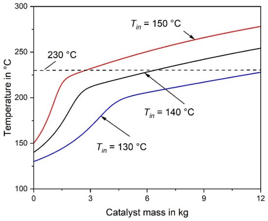
Figure 1.
Axial temperature profile of an adiabatic fixed-bed reactor for inlet temperatures of 130 °C, 140 °C and 150 °C (977 L h−1 (STP), feed gas: 0.5% CO, 16.5% CO2, 16% H2O, 67% H2). The adiabatic rise in temperature is ΔΤ = 79 K (without CO2 conversion).
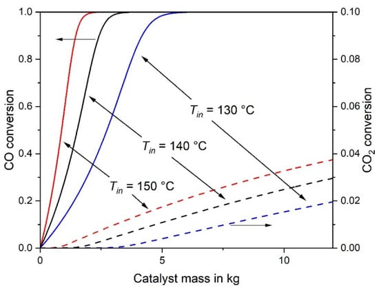
Figure 2.
CO and CO2 conversion of an adiabatic fixed-bed reactor for inlet temperatures of 130 °C, 140 °C and 150 °C (other conditions as in Figure 1).
Table 2.
Basic data of an adiabatic reactor for selective CO methanation at different initial temperatures (977 L h−1 (STP), feed gas: 0.5% CO, 16.5% CO2, 16% H2O, 67% H2).
If the inlet temperature is reduced from 140 °C to 130 °C, the mass of catalyst required for 98% CO conversion undesirably increases from 2.9 kg to 4.9 kg, and the excess of H2 consumption is almost the same (Table 2). If, vice versa, the inlet temperature is increased from 140 °C to 150 °C, the required mass of catalyst decreases from 2.9 kg to 1.8 kg. Although this seems to be beneficial, EH2 rises from 1.12 to 1.18, which is of course a disadvantage, see also Table 2. Hence, a reasonable compromise has to be made with regard to minimize both mcat and EH2, whereby the outlet temperature should be always kept below 230 °C. Figure 1 also clearly shows that the size of the reactor and mass of the catalyst, respectively, should not be too high to avoid an unwanted overheating of the catalyst (> 230 °C) as well as an undesired CO2 methanation and H2 consumption, e.g., for Tin = 140 °C and 12 kg catalyst, CO2 conversion would reach 3% and the corresponding value of EH2 would be 2.3 (H2 conversion: 5%).
However, to be on the safe side with regard to the maximum residual CO content of 100 ppm, a certain surplus of the reactor size is advisable. Therefore, Table 2 also shows the reactor parameters, if the reactor length and mass of catalyst are by a factor 1.5 larger compared to the parameters for 100 ppm residual CO content. As expected, the CO conversion is then almost 100%, but the CO2 conversion also increases, which leads to an additional and highly unwanted conversion of hydrogen (higher value of EH2), e.g., for Tin = 140 °C, XH2 increases from 2.5% to 3%.
For a feed gas with 0.7% CO, an appropriate reactor set-up is only reached for a very low inlet temperature of 110 °C. The required catalyst mass is then 25.5 kg and equals 1.5 times the minimum mass needed to reach 100 ppm (safety margin). This amount is large compared to 4.4 kg for 0.5% CO in the feed gas (Table 3). The reason is the low inlet temperature (110 °C) required to keep the reactor outlet temperature (224 °C) below the limit of 230 °C. The volume would be 68 liters, e.g., a cylinder with a length of 96 cm and 30 cm in diameter, which is quite large for a household fuel cell system.
Table 3.
Simulation results for a single stage adiabatic reactor (0.5%–0.7% CO, 16.3%–16.5% CO2, 16% H2O, rest H2). The mass of the catalyst was assumed to be by a factor of 1.5 larger (safety margin) compared to the amount required to reach a residual CO content of 100 ppm.
For a feed gas with 1% CO, a single adiabatic reactor is even inapplicable for CO methanation: The gas inlet temperature should then not exceed 70 °C in order to keep the outlet temperature below 230 °C. This would lead to an unrealistic large reactor with a catalyst mass of about 250 kg which is far beyond the acceptable size for a household fuel cell system. However, this situation can be overcome by using a multi-stage fixed bed reactor set-up as presented in the following section.
3.2. Simulation of a Two-Stage Adiabatic Fixed Bed Reactor with Intermediate Cooling
A single adiabatic fixed bed reactor is inadequate for CO inlet concentrations above 0.7%. An alternative is a two-stage reactor set-up with intermediate cooling by a heat exchanger. The feed gas enters the first reactor with a temperature of Tin,1, leading to an outlet temperature of Tout,1 = 230 °C (value of T-limit); the gas is then cooled down to the inlet temperature Tin,2 of the second adiabatic reactor. The gas leaves the second reactor with the desired CO content of 100 ppm (or less), and the temperature at the outlet is still Tout,2 ≤ 230 °C. This two-stage concept is applicable for CO concentrations of up to 1% CO, which can be considered as the maximum content relevant for a feed gas from a WGS unit. The simulation results of a feed gas with 0.5% CO are summarized exemplarily in Table 4. The gas enters both reactors with an inlet temperature of 180 °C.
Table 4.
Basic data of a two-stage adiabatic reactor set-up for selective CO methanation of a gas with 0.5% CO, 16% H2O, 16.5% CO2 and 67% H2 having a volume flow of = 977 L h−1 (STP).
The adiabatic temperature rise by the exothermic CO and CO2 methanation is depicted in Figure 3. Note that the rise in the rear part of the second reactor is not anymore proportional to the decrease of the CO concentration. This is the result of the CO2 methanation, taking place mainly in the rear part, where the CO concentration is low, which enhances the rate of CO2 methanation, see Equation (2). Figure 4 shows the CO and CO2 conversion as function of catalyst mass. In the first stage (mcat = 0.27 kg) a conversion of 71% CO is reached, and in the second stage (0.3 kg) 98%, respectively.
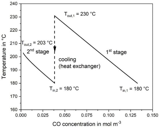
Figure 3.
Temperature change vs. CO concentration calculated at reaction conditions in the first and second adiabatic fixed bed reactor; 0.5% CO, 16.5% CO2, 16% H2O, and 67% H2 in the initial gas, 977 L h−1 (STP).
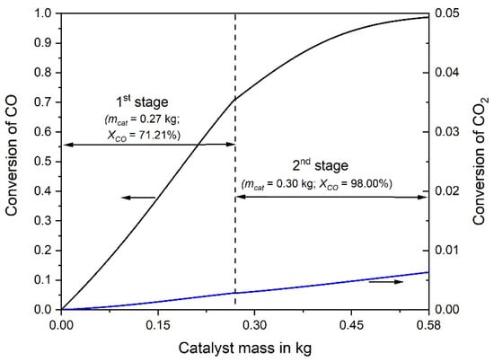
Figure 4.
Conversion of CO and CO2 vs. catalyst mass in the first and second adiabatic fixed bed reactor; 0.5% CO, 16.5% CO2, 16% H2O, and 67% H2 in the initial gas, 977 L h−1 (STP).
The mass of catalyst required for a certain CO-conversion can be calculated based on Equation (4) as
The integral of Equation (6) (and thus mcat for a given volume rate and CO inlet concentration) can be solved graphically by the plot of the reciprocal CO reaction rate versus the conversion of CO. For a comparison of the single- and the two-stage adiabatic reactor simulation, Figure 5 shows this plot for both cases. Hence, instead of a single reactor with a catalyst mass of 2.9 kg (see Section 3.1) two considerably smaller reactors can be used for the same purpose. The first one has a catalyst mass of 0.27 kg and the second one 0.3 kg, respectively, so in total only 0.57 kg catalyst. It should be noted, that for a final comparison of the single- and two-stage process, e.g., with regard to investments costs, the volume of the heat exchanger needed for the two-stage methanation has to be considered also, but this was beyond the scope of this work.
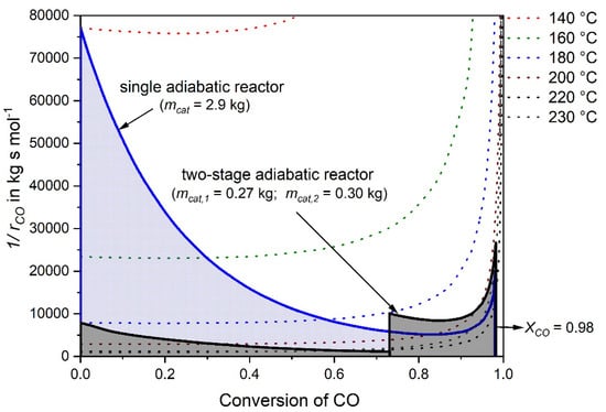
Figure 5.
Reciprocal reaction rate of CO versus conversion of CO for a feed gas with 0.5% CO, 16.5% CO2, 16% H2O, 67% H2 (rest N2) and = 977 L h−1 for two scenarios, a single adiabatic fixed bed reactor and a two-stage adiabatic fixed bed reactor with intermediate cooling.
3.3. Flexible and Safe Operation of the Two-stage Adiabatic Fixed Bed Reactor
The two-stage adiabatic reactor was further modified to ensure temperatures below 230 °C and CO concentrations at the outlet of the second reactor below 100 ppm. The modifications allowed to regulate temperature changes, CO concentration variations in the feed gas from 0% to 1% and a potential drop of catalytic activity. Here, the reactor outlet temperature was set at Tout = 220 °C (compared to 230 °C as before in the “standard” simulation), i.e., 10 °C below the critical temperature (onset of CO formation by RWGS).
Using this reactor design, the inlet temperature could be regulated (increased by about 10 K) to a certain degree depending on the catalyst activity and inlet CO concentration. The basic data of a two-stage adiabatic reactor set-up for selective CO methanation of a gas with 1% CO are listed in Table 5; the inlet temperatures are 150 °C (reactor 1) and 145 °C (reactor 2) to limit the outlet temperature of both reactors to 220 °C (Table 5). Figure 6 shows the influence of the catalyst mass on the CO and CO2 conversion, both for an inlet CO content of 0.5% and 1%. The simulation with the low CO inlet content (0.5%) already leads to a CO conversion of about 95% in the first reactor, and a very low outlet CO content of less than 2 ppm is reached in the second one, even at very low temperatures (Tin,2 = 145 °C, Tout,2 = 180 °C). In this case, the inlet temperature could be set even higher, e.g., to about 200 °C, without the danger to exceed the temperature limit of 220 °C. For 1% CO in the feed gas, the conversion in the first reactor is only about 50%, but almost full CO conversion is achieved in the second one (final CO content of 8 ppm) (Table 5).
Table 5.
Basic data of a two-stage adiabatic reactor set-up for selective CO methanation of a gas with 1% CO, 16% H2O, 16% CO2, 67% H2 having a volume flow of = 977 L h−1 (STP).
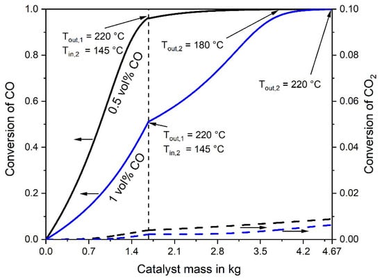
Figure 6.
Conversion of CO and CO2 vs. catalyst mass in the first and second adiabatic fixed bed reactor. Feed gas with 0.5% or 1% CO (16% CO2, 16% H2O, and about 67% H2), 977 L h−1 (STP).
Thus, the two-stage fixed bed reactor set-up could be used for the selective methanation of CO with gases containing CO concentrations up to 1%. Even in case of a drop of the catalyst’s activity, the temperature can be increased by 10 K (even for a feed gas with 1% CO) in order to keep the outlet concentration below 100 ppm and the maximum temperature below 230 °C. The catalyst mass (volume) would then be in total 4.7 kg (9.4 L), which is still a reasonable value for a household fuel cell system.
4. Conclusions
A fixed reactor for application in a typical domestic home (four-person household) was simulated based on the kinetics of CO and CO2 methanation. First, a single adiabatic fixed bed reactor was simulated for CO concentrations of 0.5%, 0.7% and 1% CO, respectively. The outlet temperature limit was set to 230 °C in order to exclude the RWGS reaction taking place at temperatures above 240 °C. The optimum inlet gas temperature was calculated for a maximum CO concentration of 100 ppm. The simulation showed that a single adiabatic reactor was suitable for up to a maximum inlet content of CO of 0.7%. For 0.5% CO in the feed gas, an inlet temperature of 140 °C resulted in a final outlet temperature of 220 °C, which was sufficiently below the critical value of 240 °C. The mass of catalyst needed in this case was about 4.4 kg for a rate of the feed gas of 977 L h−1 (STP), which can be regarded as typical for a fuel cell system of a domestic home.
For a feed gas with 1% CO, a single adiabatic fixed bed reactor turned out to be inapplicable for the selective CO methanation. The outlet temperature went too high (>240 °C) for realistic inlet temperatures (>100 °C), i.e., at an outlet temperature of 230 °C, the mass and volume of the catalyst bed were much too high if a residual CO content of 100 ppm should be reached. For this reason, a two-stage adiabatic fixed bed reactor with intermediate cooling was simulated considering an outlet temperature limitation of Tout = 230 °C. Using this device, even a feed gas with up to 1% CO could be used. Here, the resulting total mass of the catalyst was only 3.6 kg to reach the goal of less than 100 ppm CO.
However, to account for a certain decline in the activity of the catalyst and to ensure still concentrations below 100 ppm CO, the outlet temperature was lowered to Tout = 220 °C. This enables a temperature increase of about 10 K in case of a drop of the activity with time on stream. Again, a two-stage adiabatic reactor was simulated, which is applicable for varying CO concentrations of up to 1% CO. The total mass of the catalyst is then 4.7 kg (compared to 3.6 kg for an outlet temperature of 230 °C), which is still a reasonable value for a household fuel cell system.
Author Contributions
P.G. planned and carried out the experiments, the simulation and validation of the experimental data as well as data curation. A.J. was the project administrator, supervised the project and was in charge of the overall direction, planning and data curation. P.G. acquired the publication funding. A.J. and P.G. wrote, reviewed and edited the manuscript. All authors have read and agreed to the published version of the manuscript.
Funding
This work was funded by the Bavarian State Ministry of Education, Science and the Arts within the framework of the TechnologieAllianzOberfranken (TAO). This publication was funded by the German Research Foundation (DFG) and the University of Bayreuth in the funding programme Open Access Publishing.
Acknowledgments
The authors gratefully acknowledge the support of TechnolgieAllianzOberfranken and Center for Energy and Technology and thank the German Research Foundation (DFG) and the University of Bayreuth in the funding programme Open Access Publishing for funding this publication.
Conflicts of Interest
The authors declare no conflict of interest.
References
- Djinović, P.; Galletti, C.; Specchia, S.; Specchia, V. Ru-based catalysts for CO selective methanation reaction in H2-rich gases. Catal. Today 2011, 164, 282–287. [Google Scholar] [CrossRef]
- Oh, S.H.; Sinkevitch, R.M. Carbon Monoxide Removal from Hydrogen-Rich Fuel Cell Feedstreams by Selective Catalytic Oxidation. J. Catal. 1993, 142, 254–262. [Google Scholar] [CrossRef]
- Echigo, M. A study of CO removal on an activated Ru catalyst for polymer electrolyte fuel cell applications. Appl. Catal. A Gen. 2003, 251, 157–166. [Google Scholar] [CrossRef]
- Goerke, O.; Pfeifer, P.; Schubert, K. Water gas shift reaction and selective oxidation of CO in microreactors. Appl. Catal. A Gen. 2004, 263, 11–18. [Google Scholar] [CrossRef]
- Mariño, F.; Baronetti, G.; Laborde, M.; Bion, N.; Le Valant, A.; Epron, F.; Duprez, D. Optimized CuO–CeO2 catalysts for COPROX reaction. Int. J. Hydrogen Energy 2008, 33, 1345–1353. [Google Scholar] [CrossRef]
- Laguna, O.H.; Hernández, W.Y.; Arzamendi, G.; Gandía, L.M.; Centeno, M.A.; Odriozola, J.A. Gold supported on CuOx/CeO2 catalyst for the purification of hydrogen by the CO preferential oxidation reaction (PROX). Fuel 2014, 118, 176–185. [Google Scholar] [CrossRef]
- Peters, R.; Meißner, J. Gasaufbereitung für Brennstoffzellen. Chem. Ing. Tech. 2004, 76, 1555–1558. [Google Scholar] [CrossRef]
- Galletti, C.; Specchia, S.; Saracco, G.; Specchia, V. CO Methanation as Alternative Refinement Process for CO Abatement in H2-Rich Gas for PEM Applications. Int. J. Chem. React. Eng. 2007, 5. [Google Scholar] [CrossRef]
- Echigo, M.; Tabata, T. Reaction and Surface Characterization Studies of Ru/Al2O3 Catalysts for CO Preferential Oxidation in Reformed Gas. Catal. Lett. 2004, 98, 37–42. [Google Scholar] [CrossRef]
- Töpler, J.; Lehmann, J. Hydrogen and Fuel Cell; Springer: Berlin/Heidelberg, Germany, 2016; ISBN 978-3-662-44971-4. [Google Scholar]
- Garbis, P.; Kern, C.; Jess, A. Kinetics and Reactor Design Aspects of Selective Methanation of CO over a Ru/γ-Al2O3 Catalyst in CO2/H2 Rich Gases. Energies 2019, 12, 469. [Google Scholar] [CrossRef]
- Görke, O.; Pfeifer, P.; Schubert, K. Highly selective methanation by the use of a microchannel reactor. Catal. Today 2005, 110, 132–139. [Google Scholar] [CrossRef]
- PACE. Available online: pace-energy.eu (accessed on 25 February 2019).
- Viessmann. Brennstoffzellen-Heizgerät VITOVALOR PT2. Available online: https://bit.ly/2TceZql (accessed on 17 December 2019).
- Garbis, P. Kinetics and Reactor Design Aspects of Selective Methanation of CO over a Ru/γ-Al2O3 Catalyst in CO2/H2 Rich Gases. Ph.D. Thesis, Universität Bayreuth, Bayreuth, Germany, 2019. [Google Scholar]


© 2020 by the authors. Licensee MDPI, Basel, Switzerland. This article is an open access article distributed under the terms and conditions of the Creative Commons Attribution (CC BY) license (http://creativecommons.org/licenses/by/4.0/).