Water Preservation and Conservation above Coal Mines Using an Innovative Approach: A Case Study


Abstract
:1. Introduction
2. Identification of Factors Influencing WCCM
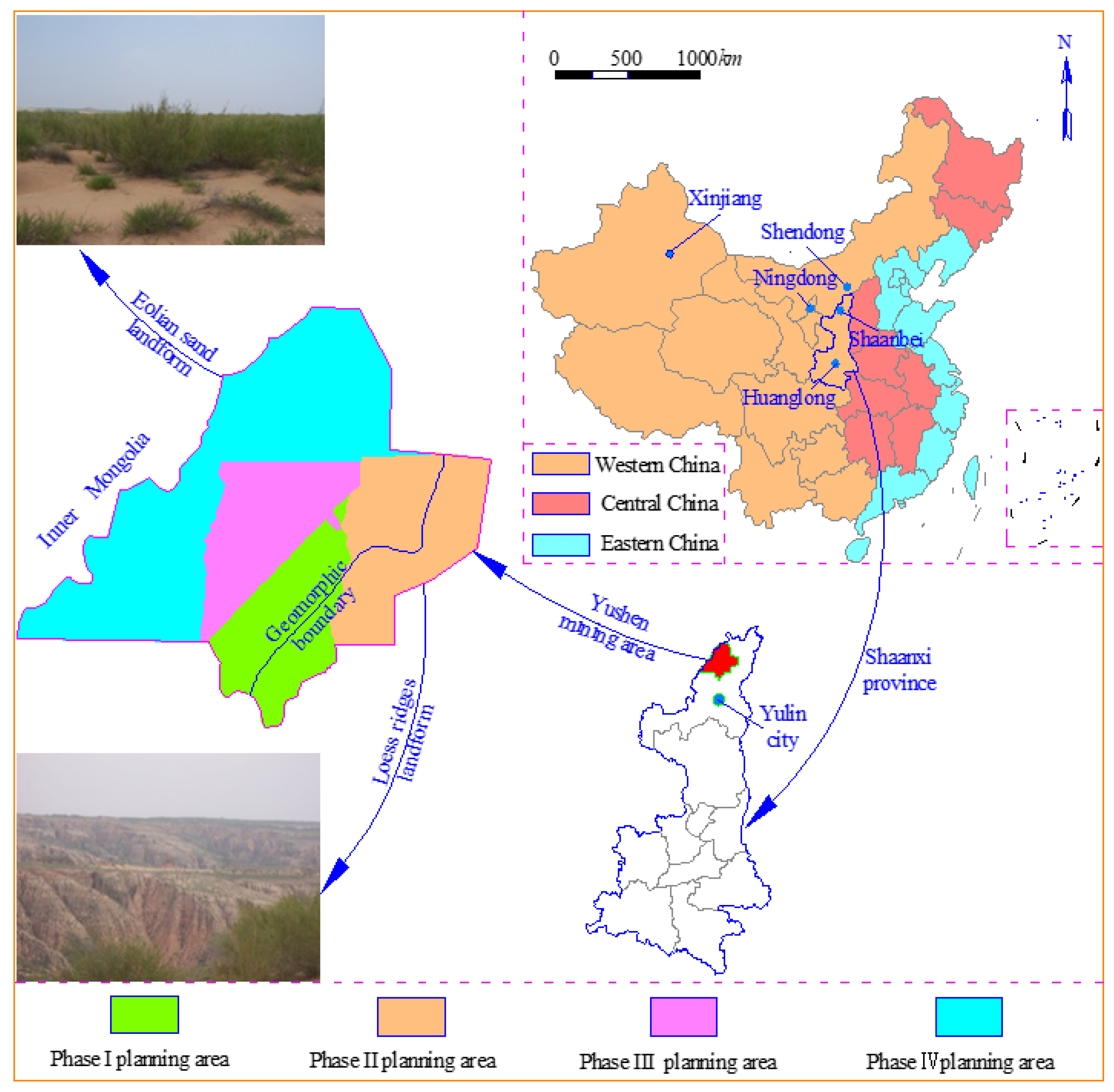
3. Overview of Yu-Shen Mining Area and Determination of “Five Maps”
3.1. Geomorphic Features
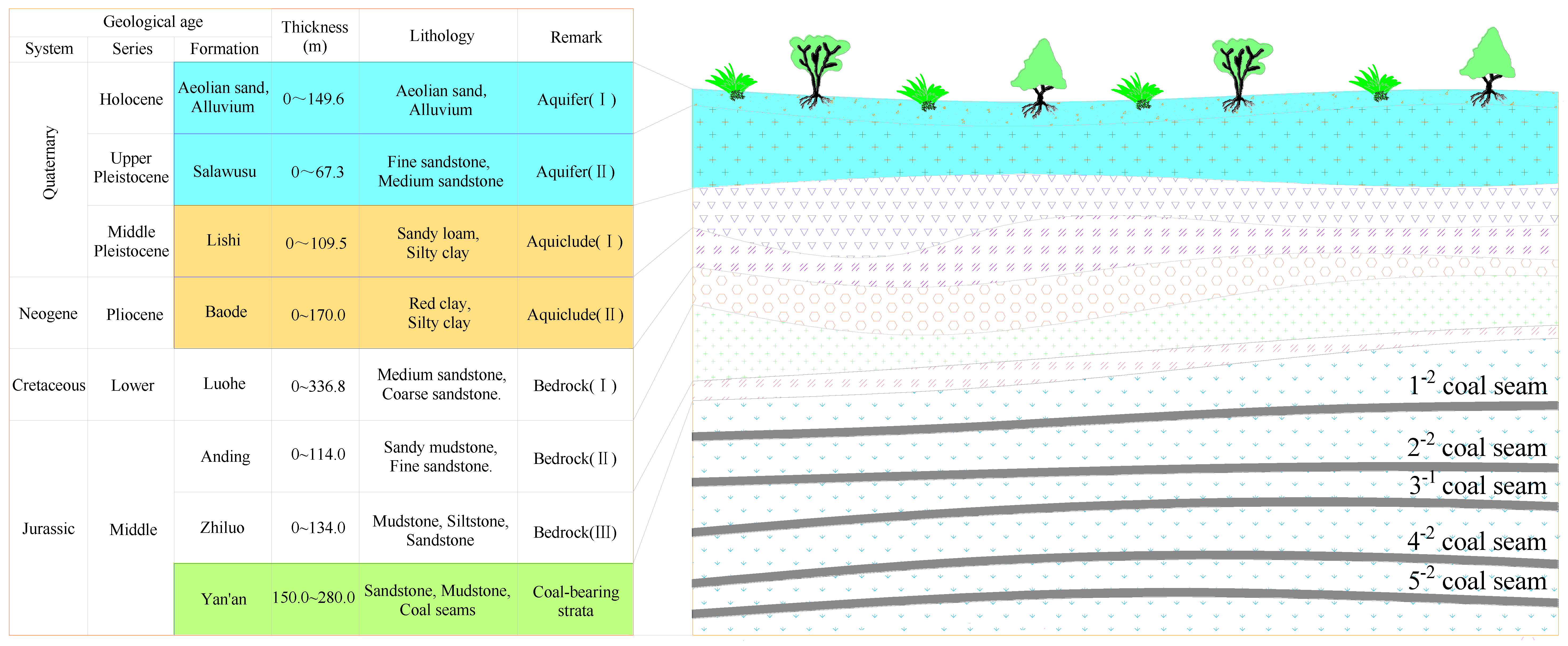
3.2. Geological Characteristics
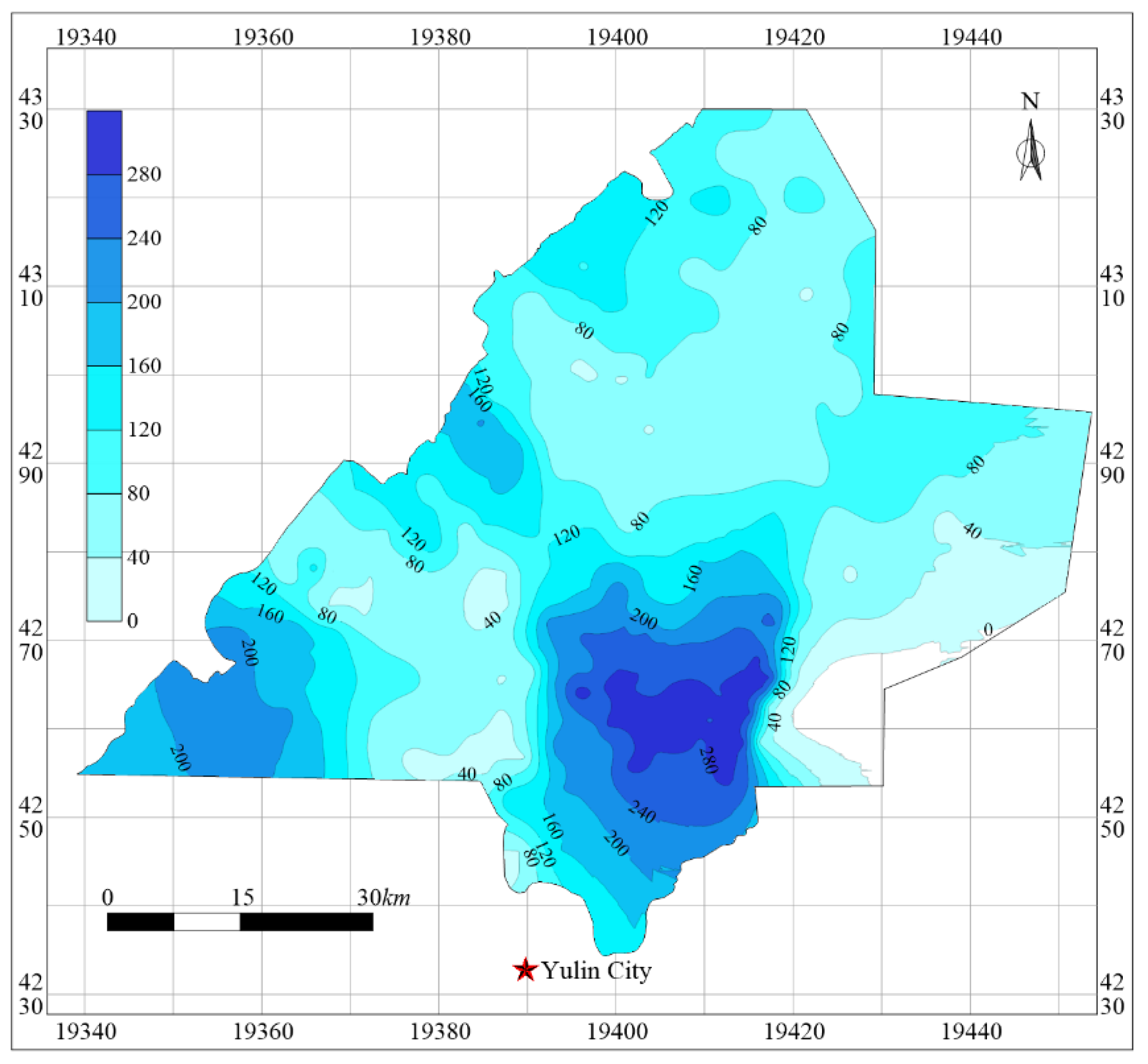
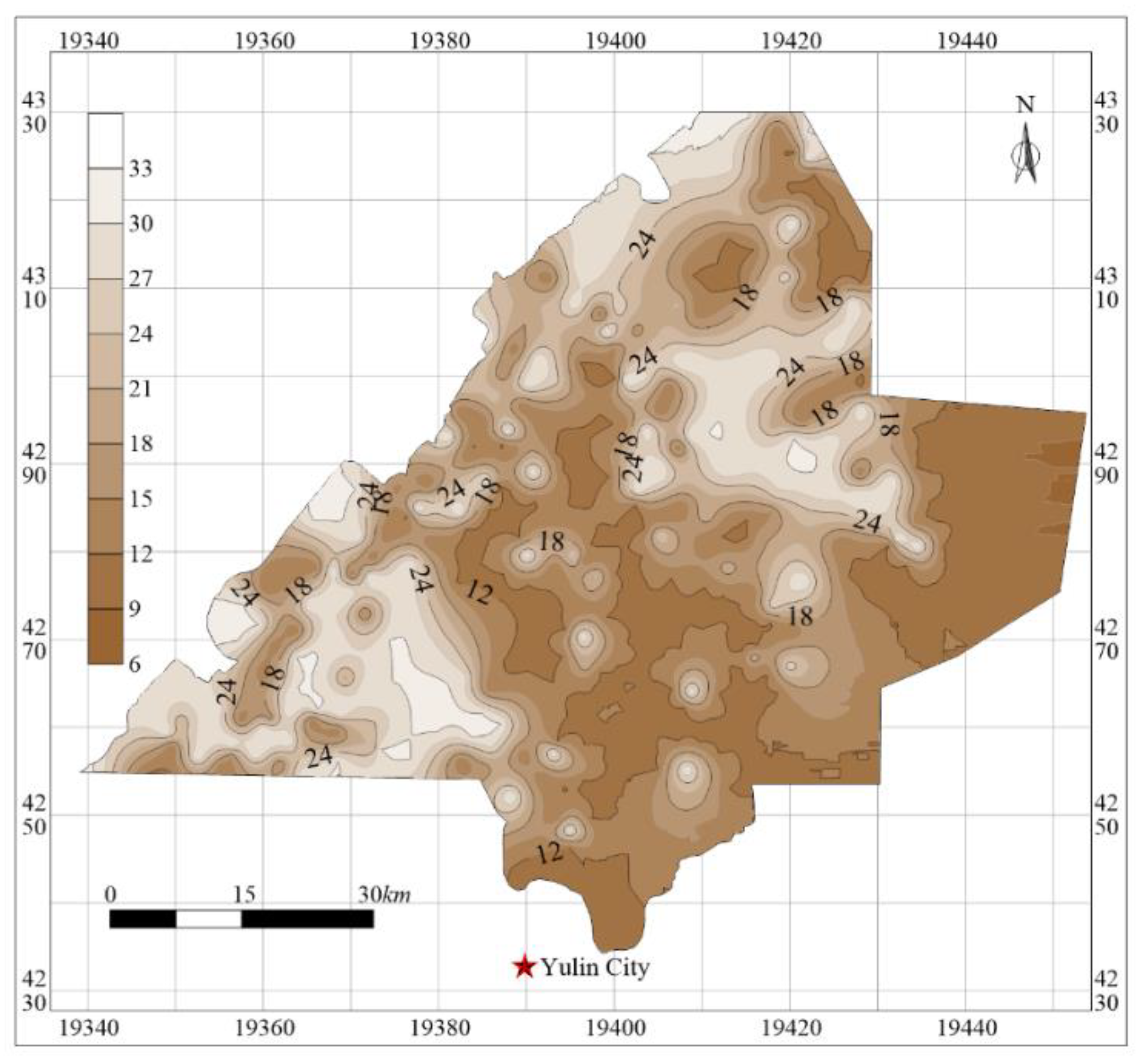
3.3. Determination of “Five Maps”
4. Determination of the Heights of “Three Zones”
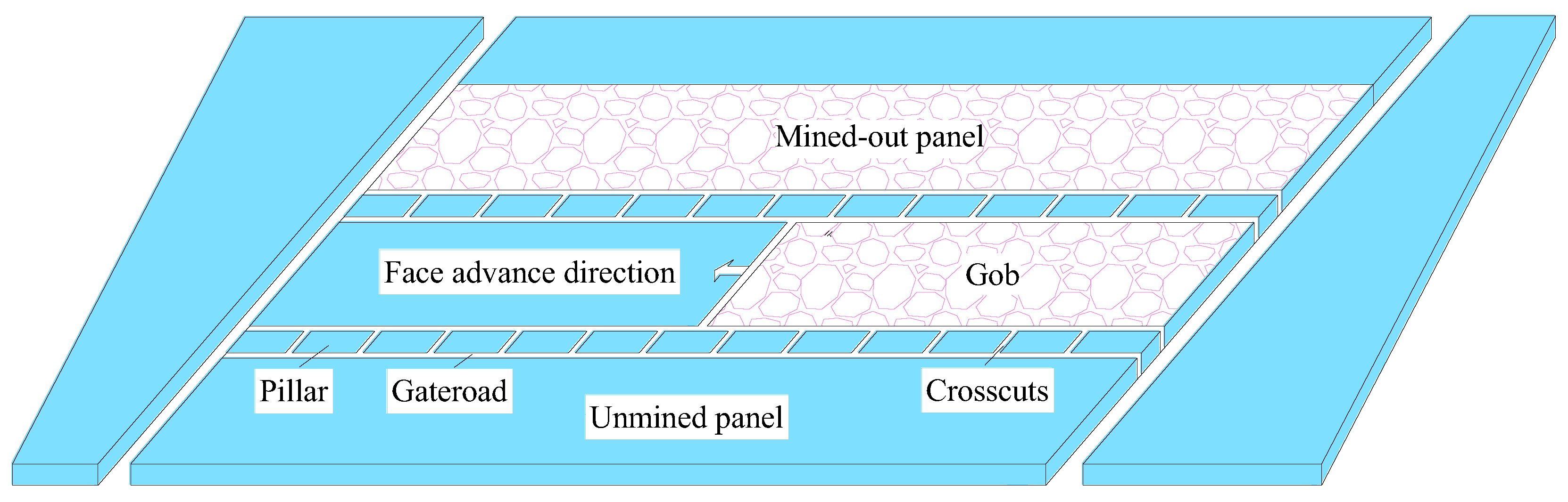
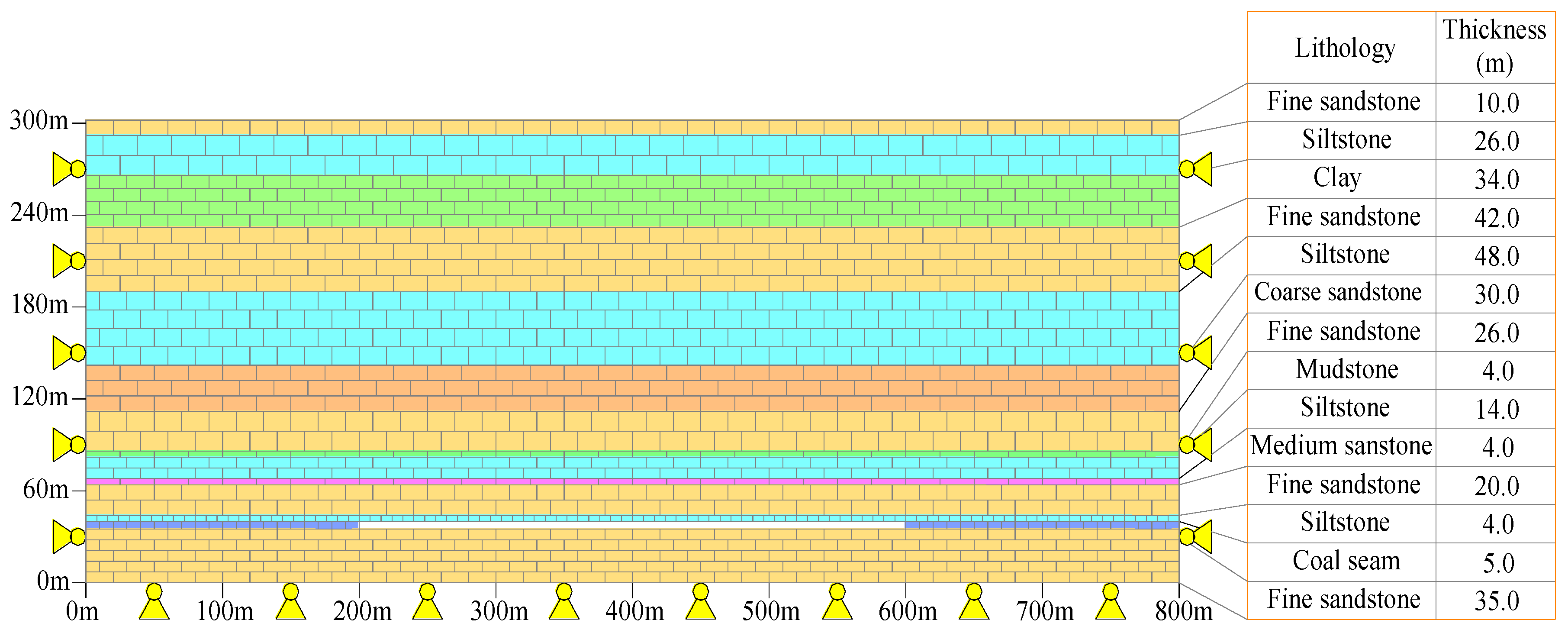
4.1. Longwall Mining
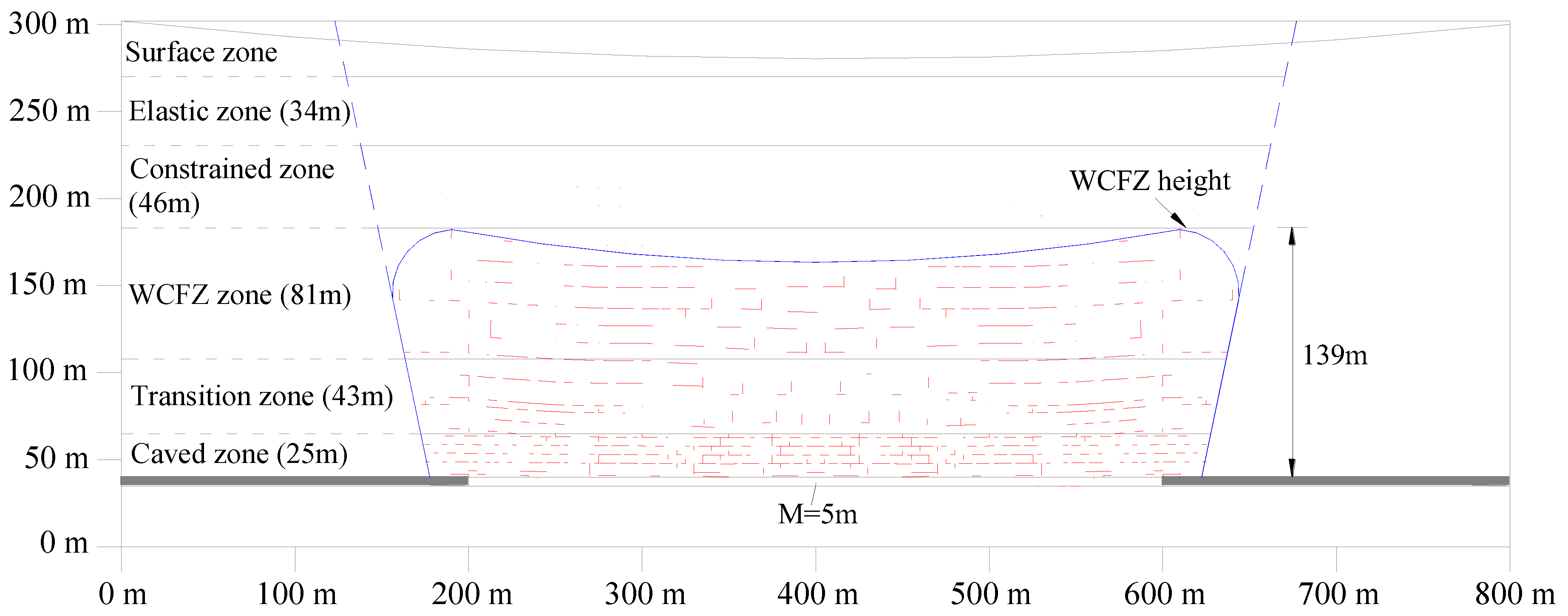
4.2. Height of Caved Zone
4.3. Height of WCFZ
4.4. Thickness of Protective Zone
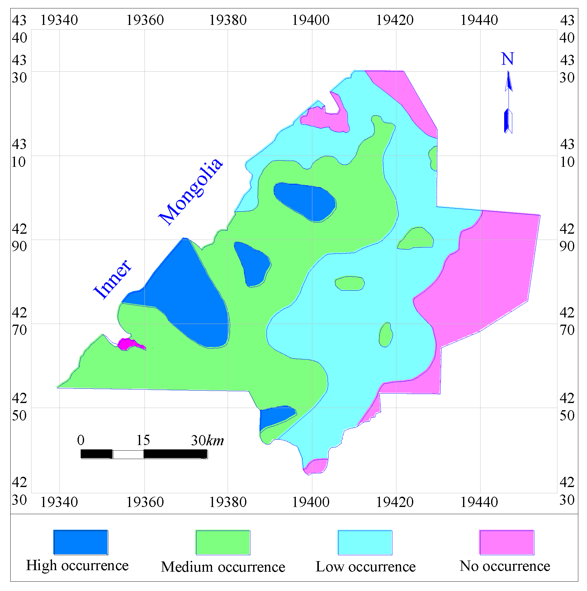
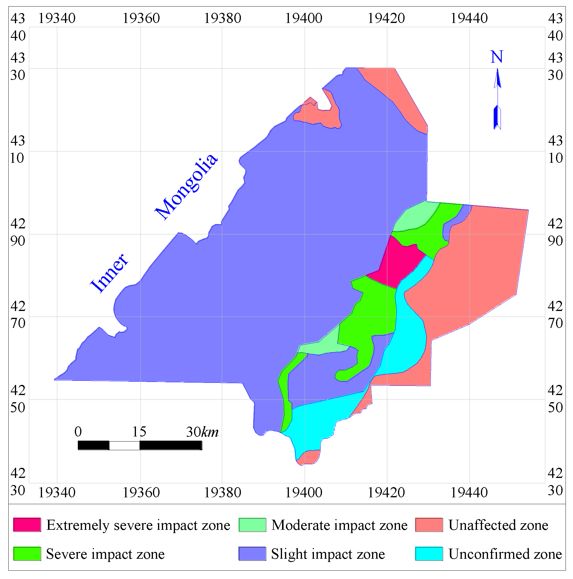
5. Zoning Based on Coal Mining’s Impact Level on Groundwater
- (1)
- Unconfirmed zone: the geological data are unavailable in this zone.
- (2)
- No impact zone: the Salawusu Formation is thin or absent, thus there is no effective aquifer.
- (3)
- Slightly impacted zone: the thickness of bedrock over the first mined seam + soil thickness > the height of WCFZ + protective zone thickness. After mining, the WCFZ and aquifer are separated by continuous strata that are thick and impermeable enough to prevent percolation. The aquifer will be effectively protected from mining-induced water loss.
- (4)
- Moderately impacted zone: the height of WCFZ < the thickness of bedrock over the first mined seam + soil thickness < the height of WCFZ + protective zone thickness. There are continuous strata with certain thickness between the WCFZ and the aquifer, but the strata are unable to completely prevent the downward percolation of water from the aquifer.
- (5)
- ‘Severely impacted zone: the height of caved zone + protective zone thickness < the thickness of bedrock over the first mined seam + soil thickness < the height of WCFZ. Mining-induced fractures will extend to the aquifer resulting in groundwater loss from the aquifer. The protective zone could only prevent sand inrush.
- (6)
- ‘Extremely impacted zone: the thickness of bedrock over the first mined seam + soil thickness < height of caved zone + protective zone thickness. Coal extraction may cause inrush of water and sand.
6. Zoning Based on Applicability of WCCM Methods
6.1. Maximum (Theoretical) Allowable Mining Height
6.2. Height-Restricted Mining
6.3. Backfill Mining
6.4. Partial Backfill Mining
6.5. Narrow Strip Mining
7. Case Studies
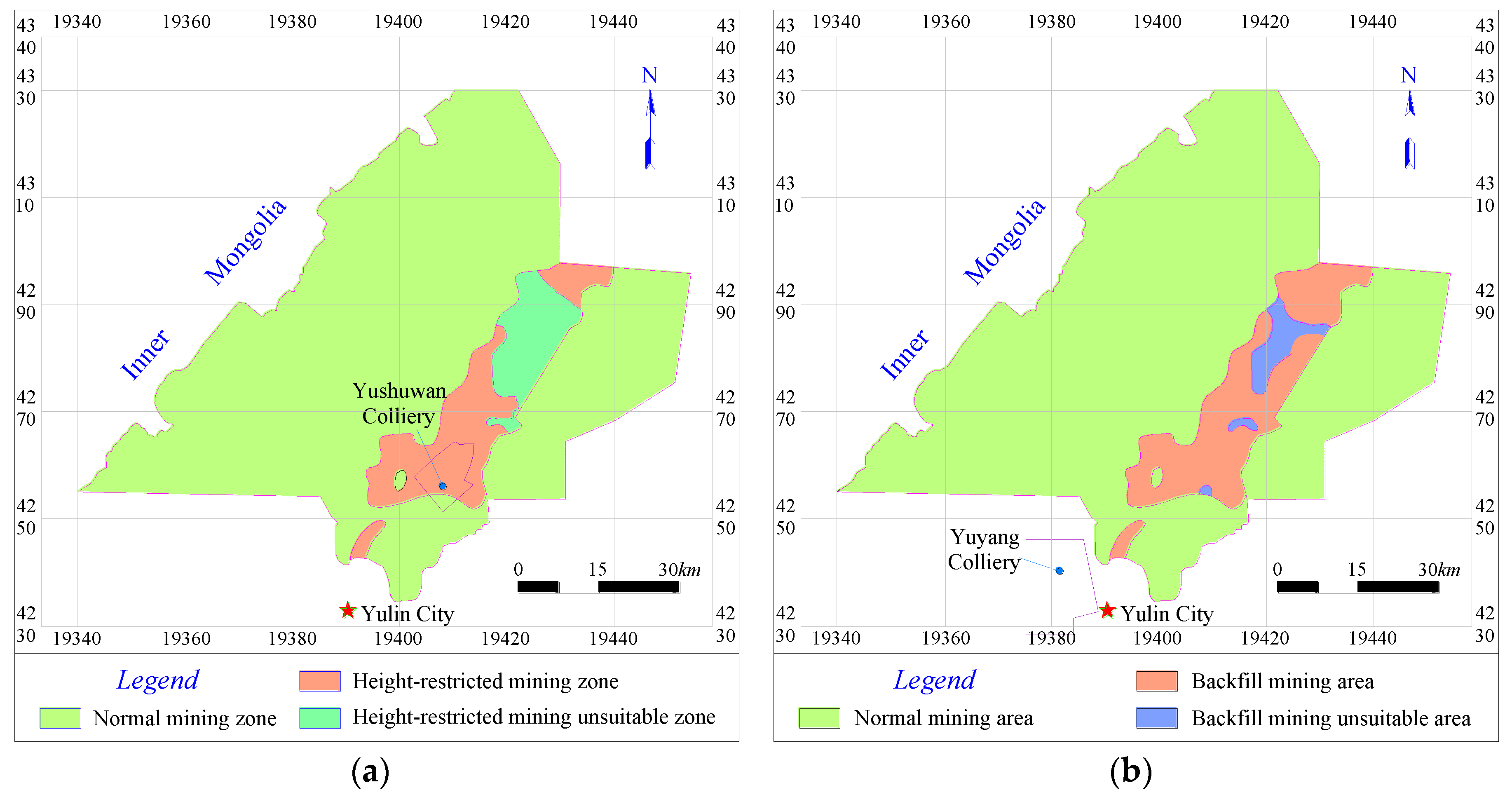
7.1. Height-Restricted Mining
7.2. Backfill Mining
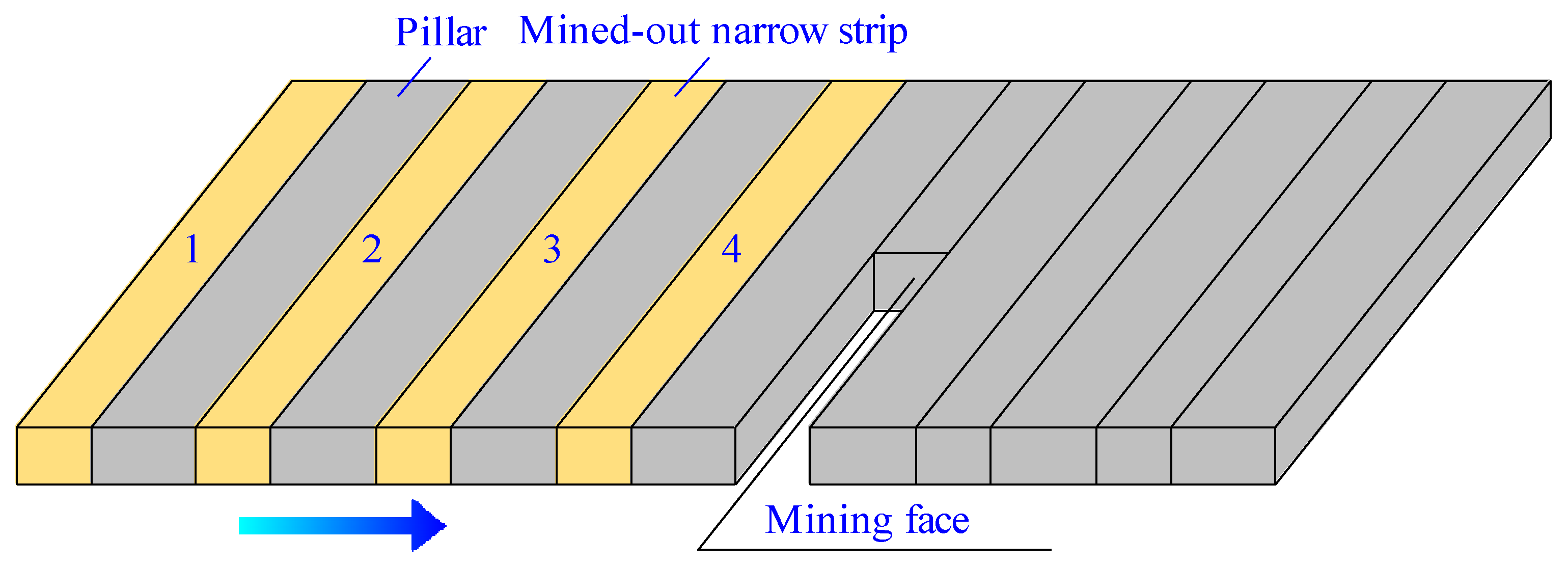
7.3. Narrow Strip Mining
8. Discussion
- (1)
- AHP is a subjective weighting method. Since the weight used in the present study was mainly provided by scholars for WCCM in Northwest China, further research is needed to confirm whether the weights determined for different influencing factors are applicable to other mining areas.
- (2)
- The proposed equation for the height of WCFZ in the Yu-Shen mining area was only related to mining height, which is similar to the empirical equation provided in the statutory regulations. According to existing empirical and theoretical research, the height of WCFZ induced by coal mining is also significantly affected by several other factors, e.g., overburden structure, roof management method, face length, and burial depth. The relationship between the height of WCFZ and these factors is nonlinear and hard to quantify. At present, no research has provided satisfactory quantitative results about the mechanisms and levels of their influences on the height of caved and fractured zones. Field production practice suggests that when a face is short (e.g. less than 50 m), the overburden can form a self-balancing arch and face length has limited influence on the height of WCFZ. Under subcritical mining condition, the height of WCFZ tends to increase with the increase of face length. Under critical mining condition, it continues to increase with the increase of face length, but the rate of increase is relatively low, and the vertical extension of this zone will basically terminate at a particular height. In terms of the relationship between the height of WCFZ and mining depth, it is found that in-situ stress rises with the increase of mining depth within a certain mining depth, and the zone of stress-relief horizontal fractures in roof strata will also expand vertically. When mining reaches a certain depth, the height of WCFZ will not increase with the increase of mining depth. This can be attributed to the high horizontal in-situ stress which could force the mining-induced stress-relief fractures to close rapidly. The data used to investigate the impact of advance rate on the height of WCFZ were generally collected two months after the face passing by. As a result, by the time of measurement, the overburden strata displacement had already become stable and the WCFZ had basically stopped developing in the vertical direction. Therefore, the results of the regression analysis based on the measurements could not reflect the actual impact of advance rate on the height of WCFZ. Under the specific geological conditions of the Yu-Shen mining area (including structure of overburden and mining depth) and mining method (including roof management method and face length), the height of WCFZ depends heavily on mining height. In addition, the coefficients in the proposed Equation also take into account the effects of overburden structure, roof management method, face length, and mining depth on WCFZ height. Thus, it is reasonable in study to derive the equation of WCFZ height by regression analysis only based on mining heights. This Equation can provide a scientific basis for WCCM, preventing water percolating from roof in Yu-Shen mining area.
- (3)
- The applicability of different WCCM methods was determined based on the specific geological conditions of the Yu-Shen mining area together with the available equipment and techniques. For example, height-restricted mining is suitable for regions where the currently used mining equipment can still be used even after imposing a height limit on it (MAMH > 2 m). Backfill mining is applicable to zones where the effective mining height (i.e. the mining height minus the height of compacted backfill) satisfies the requirement of WCCM (filling ratio = 75%). Partial backfill mining is applicable to zones where the difference between the actual height of WCFZ and its theoretical value required for water conservation is smaller than 15%. When applied to other mining areas in Northwest China, the criteria for zoning based on applicability of WCCM methods used in this study should be properly adjusted according to specific geological conditions.
- (4)
- From a technical perspective, each WCCM method has its own limitations and none of them can be applied individually to the entire mining area. In terms of applicability, backfill mining and height-restricted mining have the widest applicability, followed by partial backfill mining, and narrow strip mining has the least. Considering the low recovery rate associated with height-restricted mining, priority should be given to backfill mining when conditions apply. The applicability zones of each method are compatible with each other rather than mutually exclusive, there are overlaps between the zones suitable for different methods. The optimal WCCM method for the overlap areas should be determined with due consideration of personnel, equipment, and techniques available. Multiple WCCM methods can be used together in order to maximize economic benefits while protecting water resources. For instance, after narrow strip mining, backfill mining can be used to recover the coal pillars left. The combination of these two methods can control the development of water conductive fractures while improving coal recovery rate.
9. Conclusions
- (1)
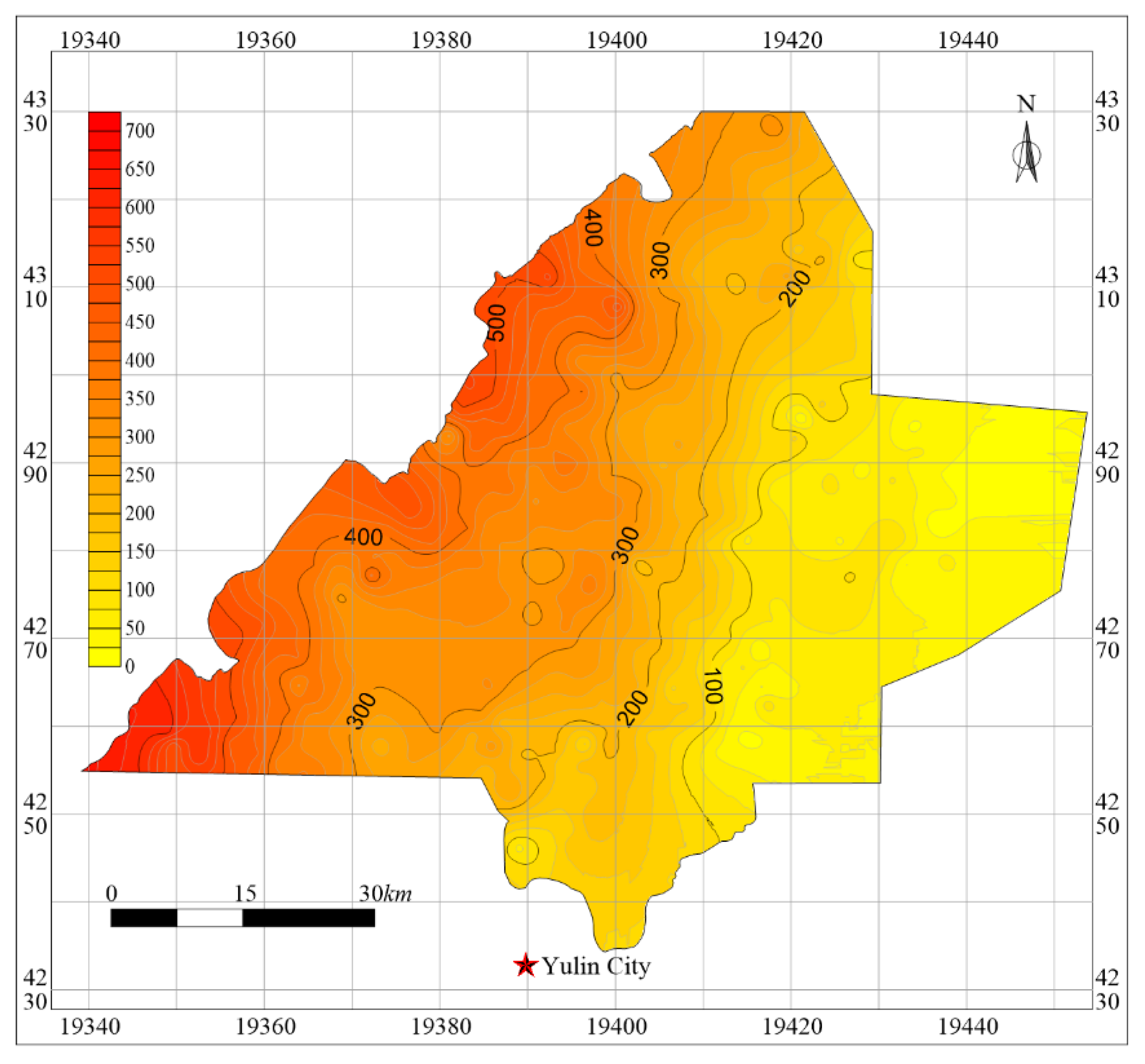
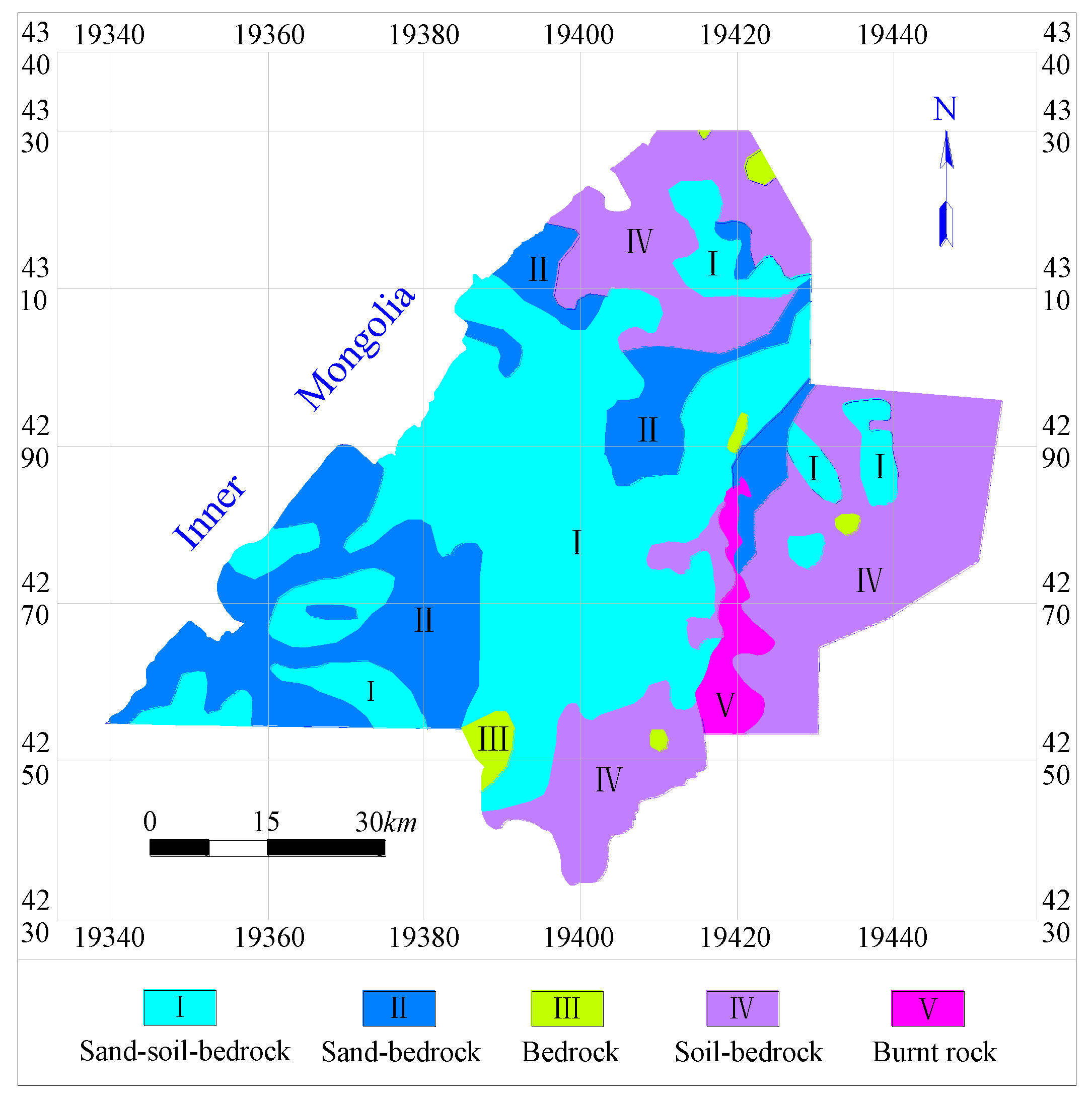
- A four-level AHP model was constructed to evaluate the influencing factors of WCCM and the weight of each influencing factor was obtained. The results show that: the overburden thickness, stratigraphic structure, the aquifer thickness, aquiclude thickness and the effective mining height are the most important factors among all influencing factors. These five most important factors are plotted as “five maps”, forming the basis for studying WCCM in the Yu-Shen mining area.
- (2)
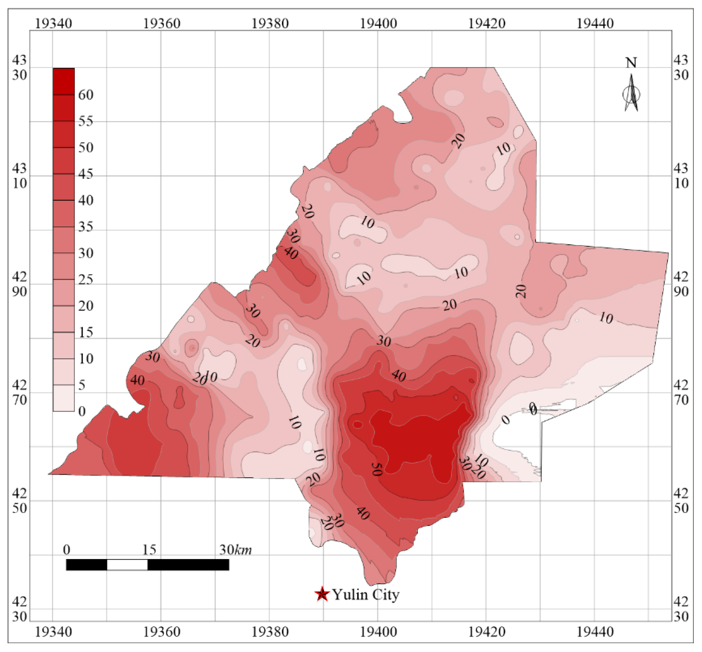
- Based on the theory analysis, field measurements and numerical simulation results, the equations were developed to predict the mining-induced heights of caved zone, WCFZ and the thickness of protective zone in the mining area. Thus three contour maps of the height of these “three zones” across the Yu-Shen mining area were obtained.
- (3)
- Based on the temporal and spatial relationship between measured bedrock thickness, soil strata thickness, heights of caved zone and WCFZ induced by mining, and the thickness of protective zone, the criterion for determining the impact of coal mining on groundwater were proposed. According to this criterion, the Yu-Shen mining area was divided into six partitions, including extremely severe impacted zone, severe impacted zone, moderate impacted zone, slight impacted zone, unaffected impacted zone and unconfirmed zone.
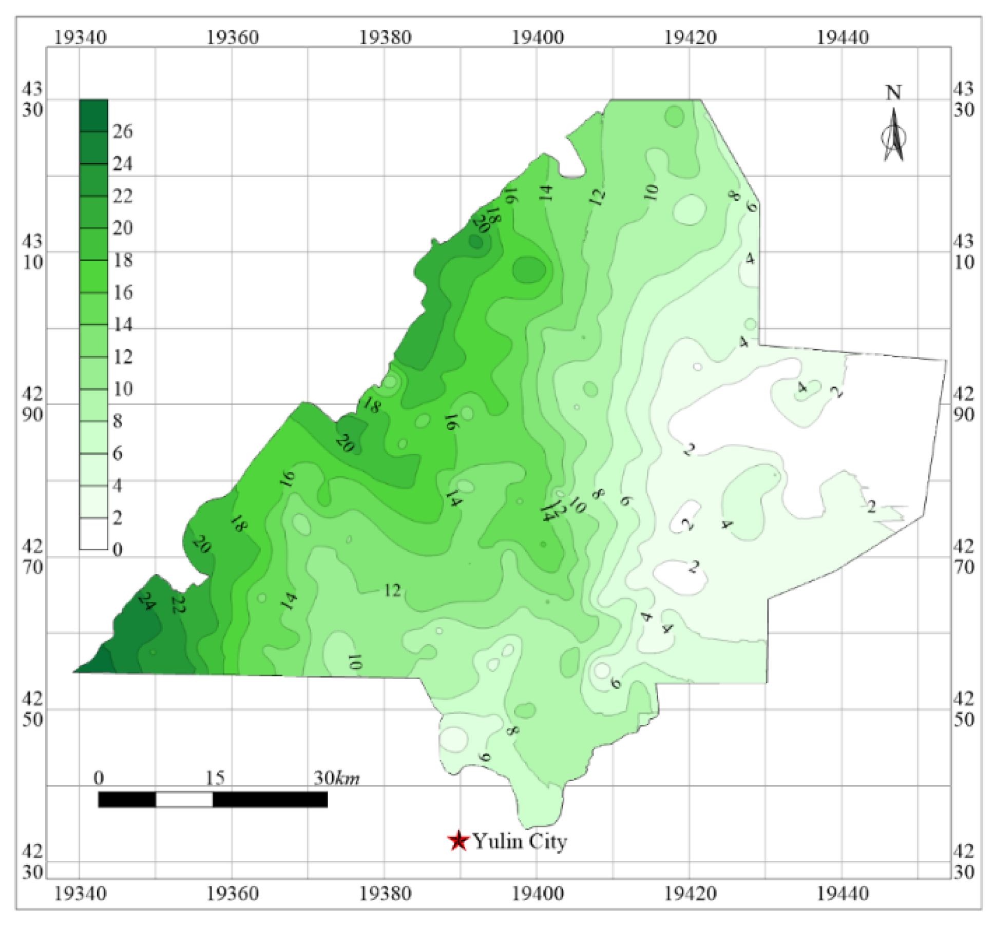
- (4)
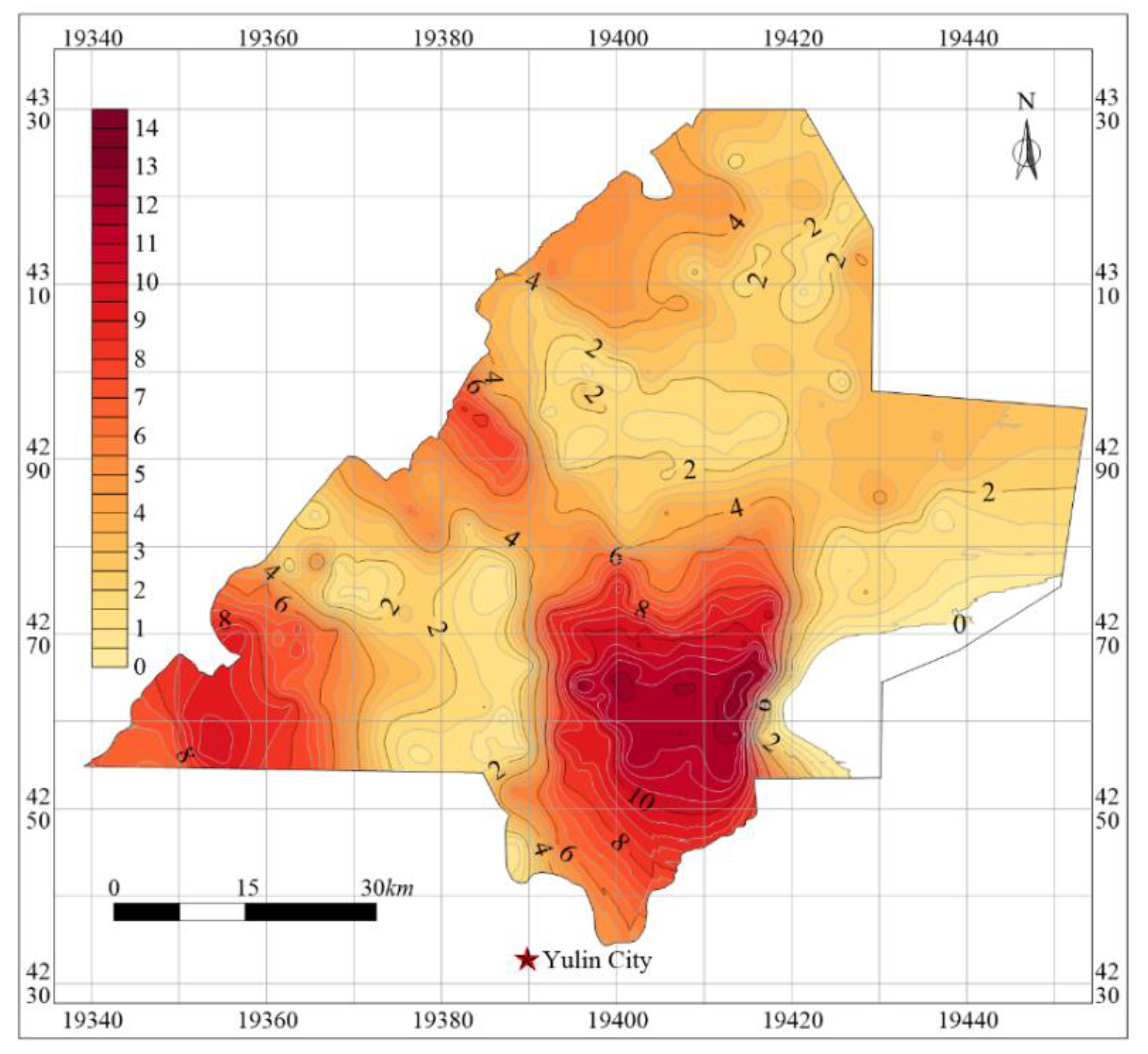
- If the thickness of soil strata plus the thickness of bedrock is greater than the height of WCFZ plus the height of protective zone, then the WCCM can be realized. Subtracting the necessary thickness of protective zone from the total thickness of soil and bedrock yields the height of WCFZ. The maximum allowable mining height (MAMH) for successful WCCM was determined by back calculation, and a contour map of MAMH was drawn for the Yu-Shen mining area.
- (5)
- The case studies proved that applicability partition of different WCCM methods, including height-restricted mining, (partial) backfilling and narrow strip mining, was a reliable tool to guide future mining in the coal area.
- (6)
- Based on this research, it can be concluded that a “five maps, three zones and two zoning plans” approach can be used in other coal mining regions in Northwest China, to optimize mining whilst limiting water disruption above the mining area.
Author Contributions
Funding
Acknowledgments
Conflicts of Interest
References
- Gu, D.Z. Theory framework and technological system of coal mine underground reservoir. J. China Coal Soc. 2015, 40, 239–246. [Google Scholar]
- Ma, L.; Jin, Z.; Liang, J.; Sun, H.; Zhang, N.; Li, P. Simulation of water resource loss in short-distance coal seams disturbed by repeated mining. Environ. Earth Sci. 2015, 74, 5653–5662. [Google Scholar] [CrossRef]
- Meng, Z.; Shi, X.; Li, G. Deformation, failure and permeability of coal-bearing strata during longwall mining. Eng. Geol. 2016, 208, 69–80. [Google Scholar] [CrossRef]
- Wang, L.; Mu, Y.; Zhang, Q.; Zhang, X. Groundwater use by plants in a semi-arid coal-mining area at the Mu Us Desert frontier. Environ. Earth Sci. 2012, 69, 1015–1024. [Google Scholar] [CrossRef]
- Yin, L.; Hou, G.; Dou, Y.; Tao, Z.; Li, Y. Hydrogeochemical and isotopic study of groundwater in the Habor Lake Basin of the Ordos Plateau, NW China. Environ. Earth Sci. 2009, 64, 1575–1584. [Google Scholar] [CrossRef]
- Adhikary, D.; Guo, H. Modelling of longwall mining-induced strata permeability change. Rock Mech. Rock Eng. 2014, 48, 345–359. [Google Scholar] [CrossRef]
- Booth, C. Groundwater as an environmental constraint of longwall coal mining. Environ. Earth Sci. 2006, 49, 796–803. [Google Scholar] [CrossRef]
- Booth, C.J. Confined-unconfined changes above longwall coal mining due to increases in fracture porosity. Environ. Eng. Geosci. 2007, 13, 355–367. [Google Scholar] [CrossRef]
- Fan, G.; Zhou, L. Mining-induced variation in water levels in unconsolidated aquifers and mechanisms of water preservation in mines. Min. Sci. Technol. (China) 2010, 20, 814–819. [Google Scholar] [CrossRef]
- Gale, W.J. Aquifer Inflow Prediction above Longwall Panels, ACARP End of Grant Report; ACARP: Brisbane, Australia, 2008; C13013; p. 96. [Google Scholar]
- Li, Y. Groundwater system for the periods of pre- and post-longwall mining over thin overburden. Int. J. Min. Reclam. Environ. 2015, 30, 295–311. [Google Scholar] [CrossRef]
- Ma, L.Q.; Sun, H.; Wang, F.; Li, J.M.; Jin, Z.Y.; Zhang, W. Analysis of the ground water level change of aquifer-protective mining in longwall coalface for shallow seam. J. Min. Saf. Eng. 2014, 31, 232–235. [Google Scholar]
- Majdi, A.; Hassani, F.P.; Nasiri, M.Y. Prediction of the height of destressed zone above the mined panel roof in longwall coal mining. Int. J. Coal Geol. 2012, 98, 62–72. [Google Scholar] [CrossRef]
- Fan, L.M. Discussing on coal mining under water-containing condition. Coal Geol. Explor. 2005, 33, 50–53. [Google Scholar]
- Fan, L.M. Scientific connotation of water-preserved mining. J. China Coal. Soc. 2017, 42, 27–35. [Google Scholar]
- Qian, M.G.; Xu, J.L.; Wang, J.C. Further on the sustainable mining of coal. J. China Coal Soc. 2018, 43, 1–13. [Google Scholar]
- Zhang, S.; Fan, G.; Liu, Y.; Ma, L. Field trials of aquifer protection in longwall mining of shallow coal seams in China. Int. J. Rock Mech. Min. Sci. 2010, 47, 908–914. [Google Scholar] [CrossRef]
- Karaman, A.; Akhiev, S.S.; Carpenter, P.J. A new method of analysis of water-level response to a moving boundary of a longwall mine. Water Resour. Res. 1999, 35, 1001–1010. [Google Scholar] [CrossRef]
- Shultz, R. Ground-water hydrology of Marshall County, West Virginia, with emphasis on the effects of longwall coal mining. Water Resour. Investig. Rep. 1988. [Google Scholar] [CrossRef]
- Booth, C.J.; Spande, E.D.; Pattee, C.T.; Miller, J.D.; Bertsch, L.P. Positive and negative impacts of longwall mine subsidence on a sandstone aquifer. Environ. Earth Sci. 1998, 34, 223–233. [Google Scholar] [CrossRef]
- Hill, J.G.; Price, D.R. The impact of deep mining on an overlying aquifer in western pennsylvania. Ground Water Monit. Remediat. 1983, 3, 138–143. [Google Scholar] [CrossRef]
- Robertson, J. Challenges in sustainably managing groundwater in the Australian Great Artesian Basin: Lessons from current and historic legislative regimes. Hydrogeol. J. 2019, 28, 343–360. [Google Scholar] [CrossRef] [Green Version]
- Howladar, M.F. Coal mining impacts on water environs around the Barapukuria coal mining area, Dinajpur, Bangladesh. Environ. Earth Sci. 2012, 70, 215–226. [Google Scholar] [CrossRef]
- Gandhe, A.; Venkateswarlu, V.; Gupta, R.N. Extraction of coal under a surface water body—A strata control investigation. Rock Mech. Rock Eng. 2005, 38, 399–410. [Google Scholar] [CrossRef]
- Fan, L.M.; Xiang, M.X.; Peng, J.; Li, C.; Li, Y.H.; Wu, B.Y.; Bian, H.Y.; Gao, S.; Qiao, X.Y. Groundwater response to intensive mining in ecologically fragile area. J. China Coal Soc. 2016, 41, 2672–2678. [Google Scholar]
- Wang, S.M.; Huang, Q.X.; Fan, L.M.; Yang, Z.Y.; Shen, T. Study on overburden aquiclude and water protection mining regionazation in the ecological fragile mining area. J. China Coal Soc. 2010, 35, 7–14. [Google Scholar]
- Miao, X.X.; Chen, R.H.; Bai, H.B. Fundamental concepts and mechanical analysis of water resisting key strata in water preserved mining. J. China Coal Soc. 2017, 32, 561–564. [Google Scholar]
- Huang, Q.X. Research on roof control of water conservation mining in shallow seam. J. China Coal Soc. 2017, 42, 50–55. [Google Scholar]
- Zhang, D.S.; Li, W.P.; Lai, X.P.; Fan, G.W.; Liu, W.Q. Development on basic theory of water protection during coal mining in northwest of China. J. China Coal Soc. 2017, 42, 36–43. [Google Scholar]
- Ma, L.Q.; Zhang, D.S.; Dong, Z.Z. Evolution mechanism and process of aquiclude fissures. J. Min. Saf. Eng. 2011, 28, 340–344. [Google Scholar]
- Ma, L.Q.; Cao, X.Q.; Liu, Q.; Zhou, T. Simulation study on water-preserved mining in multi-excavation disturbed zone in close-distance seams. Environ. Eng. Manag. J. 2013, 12, 1849–1853. [Google Scholar] [CrossRef]
- Ma, L.Q.; Du, X.; Wang, F.; Liang, J.M. Water-preserved Mining Technology for Shallow Buried Coal Seam in Ecologically-vulnerable Coal field: A case study in the Shendong Coal field of China. Disaster Adv. 2013, 6, 268–278. [Google Scholar]
- Wang, A.; Ma, L.; Wang, Z.; Zhang, D.; Li, K.; Zhang, Y.; Yi, X. Soil and water conservation in mining area based on ground surface subsidence control: Development of a high-water swelling material and its application in backfilling mining. Environ. Earth Sci. 2016, 75, 779. [Google Scholar] [CrossRef]
- Li, M.; Zhang, J.; Huang, P.; Gao, R. Mass ratio design based on compaction properties of backfill materials. J. Cent. South. Univ. 2016, 23, 2669–2675. [Google Scholar] [CrossRef]
- Wu, Q. Progress, problems and prospects of prevention and control technology of mine water and reutilization in China. J. China Coal Soc. 2014, 39, 795–805. [Google Scholar]
- Zhang, D.S.; Liu, H.L.; Fan, G.W.; Wang, X.F. Connotation and prospection on scientific mining of large Xinjiang coal base. J. Min. Saf. Eng. 2015, 32, 1–6. [Google Scholar]
- Zhang, S.; Fan, G.; Ma, L.; Wang, X. Aquifer protection during longwall mining of shallow coal seams: A case study in the Shendong Coalfield of China. Int. J. Coal Geol. 2011, 86, 190–196. [Google Scholar] [CrossRef]
- Li, W.P.; Ye, G.J.; Zhang, L.; Duan, Z.H.; Zhai, L.J. Study on the engineering geological conditions of protected water resources during coal mining action in Yu-Shen Mine Area in the North Shanxi Province. J. China Coal Soc. 2000, 25, 449–454. [Google Scholar]
- Du, J.P.; Meng, X.R. Mining Science; China University of Mining and Technology Press: Xuzhou, China, 2014. [Google Scholar]
- Peng, S.Y. Coal Mine Ground Control; China University of Mining and Technology Press: Xuzhou, China, 2013. [Google Scholar]
- Sui, W.; Hang, Y.; Ma, L.; Wu, Z.; Zhou, Y.; Long, G.; Wei, L. Interactions of overburden failure zones due to multiple-seam mining using longwall caving. Bull. Int. Assoc. Eng. Geol. 2014, 74, 1019–1035. [Google Scholar] [CrossRef] [Green Version]
- Miao, J.K.; Jiang, Z.Q. Research on the height of water flowing fractured zone in the fully mechanized mining face by drilling exploration. Shaanxi Coal 2014, 33, 33–36. [Google Scholar]
- Wei, J.C.; Wu, F.Z.; Xie, D.L.; Yin, H.Y.; Guo, J.B.; Xiao, L.L. Development characteristic of water flowing fractured zone under semi-cemented medium-low strength country rock. J. China Coal Soc. 2016, 41, 974–983. [Google Scholar]
- Yin, S.X.; Xu, B.; Xu, H.; Xia, X.X. The research on the height of the “Two zones” in Zhuozishan coalfield. Disaster Adv. 2013, 6, 78–84. [Google Scholar]
- Gao, B.B.; Liu, Y.P.; Pan, J.Y.; Yuan, T. Detection and analysis of height of water flowing fractured zone in underwater mining. Chin. J. Rock Mech. Eng. 2014, 33, 3384–3390. [Google Scholar]
- Huang, H.F.; Yan, Z.G.; Yao, B.H.; Xu, H.J. Research on the process of fracture development in overlying rocks under coal seams group mining in Wanli mining area. J. Min. Saf. Eng. 2012, 29, 619–624. [Google Scholar]
- Wang, F.; Tu, S.; Zhang, C.; Zhang, Y.; Bai, Q. Evolution mechanism of water-flowing zones and control technology for longwall mining in shallow coal seams beneath gully topography. Environ. Earth Sci. 2016, 75, 1309. [Google Scholar] [CrossRef]
- Xu, Y.C. Design methods of the effective water-resisting thickness for the protective seam of the water barrier in fully-caving mechanized coalmining. J. China Coal Soc. 2005, 30, 305–308. [Google Scholar]
- Fan, L.M.; Ma, X.D.; Ji, R.J. The progress of research and engineering practice of water-preserved coal mining in western eco-environment frangible area. J. China Coal Soc. 2015, 40, 1711–1717. [Google Scholar]
- Qian, M.G.; Miao, X.X.; Xu, J.L. Green mining of coal resources harmonizing with environment. J. China Coal Soc. 2007, 32, 1–7. [Google Scholar]
- Shi, B.Q. Research on water-preserved-mining in shallow seam covered with rock soil and sand in Northern Shaanxi. J. Min. Saf. Eng. 2011, 28, 548–552. [Google Scholar]
- Lv, W.H. The application of the backfill mining in Yu-yang coal area. Sci. Technol. Innov. Her. 2013, 33, 48–50. [Google Scholar]
- Wang, W.X.; Sui, W.; Faybishenko, B.; Stringfellow, W. Permeability variations within mining-induced fractured rock mass and its influence on groundwater inrush. Environ. Earth Sci. 2016, 75, 326. [Google Scholar] [CrossRef]
- Chi, M.; Zhang, D.; Liu, H.; Wang, H.; Zhou, Y.; Zhang, S.; Yu, W.; Luang, S.; Zhao, Q. Simulation analysis of water resource damage feature and development degree of mining-induced fracture at ecologically fragile mining area. Environ. Earth Sci. 2019, 78, 88. [Google Scholar] [CrossRef]
- Lu, Y.; Wang, L. Numerical simulation of mining-induced fracture evolution and water flow in coal seam floor above a confined aquifer. Comput. Geotech. 2015, 67, 157–171. [Google Scholar] [CrossRef]
- Hollá, L.; Buizen, M. The ground movement, strata fracturing and changes in permeability due to deep longwall mining. Int. J. Rock Mech. Min. Sci. Géoméch. Abstr. 1991, 28, 207–217. [Google Scholar] [CrossRef]


| Compound Factor Weight B | Sub-Factor Weight C | Sub-Factor Weight D | Sub-Factor Weight E | ||||
|---|---|---|---|---|---|---|---|
| 1. Engineering and geological conditions B1 | 0.347 | Overburden thickness C1 | 0.096 | 0.096 | 0.096 | ||
| Lithology C2 | 0.070 | 0.070 | 0.070 | ||||
| Physical and mechanical properties C3 | 0.080 | 0.080 | 0.080 | ||||
| Stratigraphic structure C4 | 0.084 | 0.084 | 0.084 | ||||
| Geological structure C5 | 0.017 | Faults D1 | 0.013 | ① Fault density E1 | 0.006 | ||
| ② Fault length E2 | 0.003 | ||||||
| ③ Fault throw index E3 | 0.004 | ||||||
| Folds D2 | 0.004 | ① Fold section coefficient E4 | 0.0022 | ||||
| ② Fold plane coefficient E5 | 0.0018 | ||||||
| 2. Hydrogeological conditions B2 | 0.539 | Aquifer C6 | 0.202 | Recharge D3 | 0.082 | 0.082 | |
| Thickness D4 | 0.040 | 0.040 | |||||
| Permeability coefficient D5 | 0.039 | 0.039 | |||||
| Groundwater depth D6 | 0.016 | 0.016 | |||||
| Vertically adjacent aquifers water difference D7 | 0.025 | 0.025 | |||||
| Aquiclude C7 | 0.337 | Thickness D8 | 0.179 | 0.179 | |||
| Horizon D9 | 0.031 | 0.031 | |||||
| (3) Water-physical properties D10 | 0.127 | ① Permeability E6 | 0.071 | ||||
| ② Expansibility E7 | 0.033 | ||||||
| ③ Water sensibilityE8 | 0.023 | ||||||
| 3. Mining method B3 | 0.114 | Mining methods C8 | 0.019 | 0.019 | 0.019 | ||
| Mining parameters C9 | 0.095 | Effective mining height D11 | 0.067 | 0.067 | |||
| Working face inclination D12 | 0.0075 | 0.0075 | |||||
| Mining depth D13 | 0.0085 | 0.0085 | |||||
| Advance velocity D14 | 0.003 | 0.003 | |||||
| Working face dimensions D15 | 0.003 | ① Inclination length E9 | 0.002 | ||||
| ② Strike length E10 | 0.001 | ||||||
| Coal pillar stability D16 | 0.006 | ① Coal pillar sizes E11 | 0.0032 | ||||
| ② Coal mechanical properties E12 | 0.0028 | ||||||
| Total | 1.0 | Total | 1.000 | Total | 1.0000 | Total | 1.0000 |
| Coal Mine | Working Face/Borehole | Mining Height (m) | Caved Zone Height (m) | The Ratio of Caved Zone Height to Mining Height | WCFZ Height (m) | The Ratio of WCFZ Height to Mining Height |
|---|---|---|---|---|---|---|
| Yuyang | 2304 | 3.5 | 17.2 | 4.91 | 96.3 | 27.51 |
| Jinjitan | 101 | 5.5 | 23.14 | 4.2 | 108.59 | 20.54 |
| Yushuwan | Y3 | 5 | 24.50 | 4.90 | 130.50 | 26.10 |
| Y4 | 5 | 27.90 | 5.58 | 137.30 | 27.46 | |
| Y5 | 5 | 27.10 | 5.42 | 138.90 | 27.78 | |
| Y6 | 5 | 20.60 | 4.12 | 117.80 | 23.56 | |
| Hanglaiwan | H3 | 4.5 | 20.50 | 4.56 | 108.32 | 24.07 |
| H4 | 4.5 | 22.18 | 4.93 | 114.38 | 25.42 | |
| H5 | 4.5 | 19.40 | 4.31 | 107.83 | 23.96 | |
| H6 | 4.5 | 28.70 | 6.38 | 93.87 | 20.86 |
| Number | Strata | Thickness (m) | Density (kg/m3) | Bulk Modulus (GPa) | Shear Modulus (GPa) | Cohesion (MPa) | Friction Angle (°) | Tensile Strength (MPa) |
|---|---|---|---|---|---|---|---|---|
| 1 | Fine sandstone | 10 | 2600 | 30.8 | 20.3 | 5.6 | 35 | 4.0 |
| 2 | Siltstone | 26 | 2460 | 16.1 | 11.6 | 2.0 | 21 | 1.2 |
| 3 | Clay | 34 | 1900 | 0.28 | 0.093 | 0.85 | 25 | 0.35 |
| 4 | Coarse sandstone | 30 | 2500 | 20.8 | 11.9 | 3.0 | 23 | 1.4 |
| 5 | Mudstone | 4 | 2200 | 8.3 | 4.3 | 2.1 | 25 | 1.0 |
| 6 | Medium sandstone | 4 | 2560 | 23.1 | 14.5 | 4.4 | 2.8 | 2.0 |
| 7 | Coal seam | 10 | 1400 | 2.0 | 1.4 | 1.7 | 28 | 1.5 |
| Number | Strata | Normal Stiffness (GPa) | Shear Stiffness (GPa) | Cohesion (MPa) | Friction Angle (°) | Tensile Strength (MPa) |
|---|---|---|---|---|---|---|
| 1 | Fine sandstone | 300 | 200 | 6.5 | 12 | 3.5 |
| 2 | Siltstone | 200 | 160 | 8.0 | 10 | 5.5 |
| 3 | Clay | 300 | 180 | 6.0 | 20 | 3.0 |
| 4 | Coarse sandstone | 500 | 400 | 4.0 | 25 | 3.0 |
| 5 | Mudstone | 300 | 100 | 2.1 | 20 | 1.5 |
| 6 | Medium sandstone | 150 | 100 | 4.2 | 15 | 2.2 |
| 7 | Coal seam | 500 | 350 | 9.0 | 15 | 6.0 |
| Mining Height (m) | Sand-Soil-Bedrock | Sand-Bedrock | Bedrock | Soil-Bedrock | ||||
|---|---|---|---|---|---|---|---|---|
| WCFZ Height (m) | The Ratio of WCFZ Height to Mining Height | WCFZ Height (m) | The Ratio of WCFZ Height to Mining Height | WCFZ Height (m) | The Ratio of WCFZ Heightto Mining Height | WCFZ Height (m) | The Ratio of WCFZ Height to Mining Height | |
| 2 | 64 | 32.0 | 68 | 34.0 | 53 | 26.5 | 67 | 33.5 |
| 3 | 92 | 30.7 | 101 | 33.7 | 78 | 26.0 | 91 | 30.3 |
| 4 | 119 | 29.8 | 131 | 32.8 | 101 | 25.3 | 113 | 28.3 |
| 5 | 139 | 27.8 | 154 | 30.8 | 122 | 24.4 | 141 | 28.2 |
| 6 | 165 | 27.5 | 179 | 29.8 | 138 | 23.0 | 169 | 28.2 |
| 7 | 184 | 26.3 | 200 | 28.6 | 153 | 21.9 | 190 | 27.1 |
| 8 | 208 | 26.0 | 221 | 27.6 | 170 | 21.3 | 211 | 26.4 |
| 9 | 218 | 24.2 | 235 | 26.1 | 177 | 19.7 | 226 | 25.1 |
| 10 | 240 | 24.0 | 244 | 24.4 | 187 | 18.7 | 234 | 23.4 |
| Extremely Severe Impacted Zone | Severe Impacted Zone | Moderate Impacted Zone | Slight Impacted Zone |
|---|---|---|---|
| H + Ht < Hk + Hb | Hk + Hb < H + Ht < Hd | Hd < H + Ht < Hd + Hb | H + Ht > Hd + Hb |
© 2020 by the authors. Licensee MDPI, Basel, Switzerland. This article is an open access article distributed under the terms and conditions of the Creative Commons Attribution (CC BY) license (http://creativecommons.org/licenses/by/4.0/).
Share and Cite
Xu, Y.; Ma, L.; Yu, Y. Water Preservation and Conservation above Coal Mines Using an Innovative Approach: A Case Study. Energies 2020, 13, 2818. https://doi.org/10.3390/en13112818
Xu Y, Ma L, Yu Y. Water Preservation and Conservation above Coal Mines Using an Innovative Approach: A Case Study. Energies. 2020; 13(11):2818. https://doi.org/10.3390/en13112818
Chicago/Turabian StyleXu, Yujun, Liqiang Ma, and Yihe Yu. 2020. "Water Preservation and Conservation above Coal Mines Using an Innovative Approach: A Case Study" Energies 13, no. 11: 2818. https://doi.org/10.3390/en13112818
APA StyleXu, Y., Ma, L., & Yu, Y. (2020). Water Preservation and Conservation above Coal Mines Using an Innovative Approach: A Case Study. Energies, 13(11), 2818. https://doi.org/10.3390/en13112818