Optimisation and Management of Energy Generated by a Multifunctional MFC-Integrated Composite Chassis for Rail Vehicles

 ,
,  , ,
, ,
Abstract
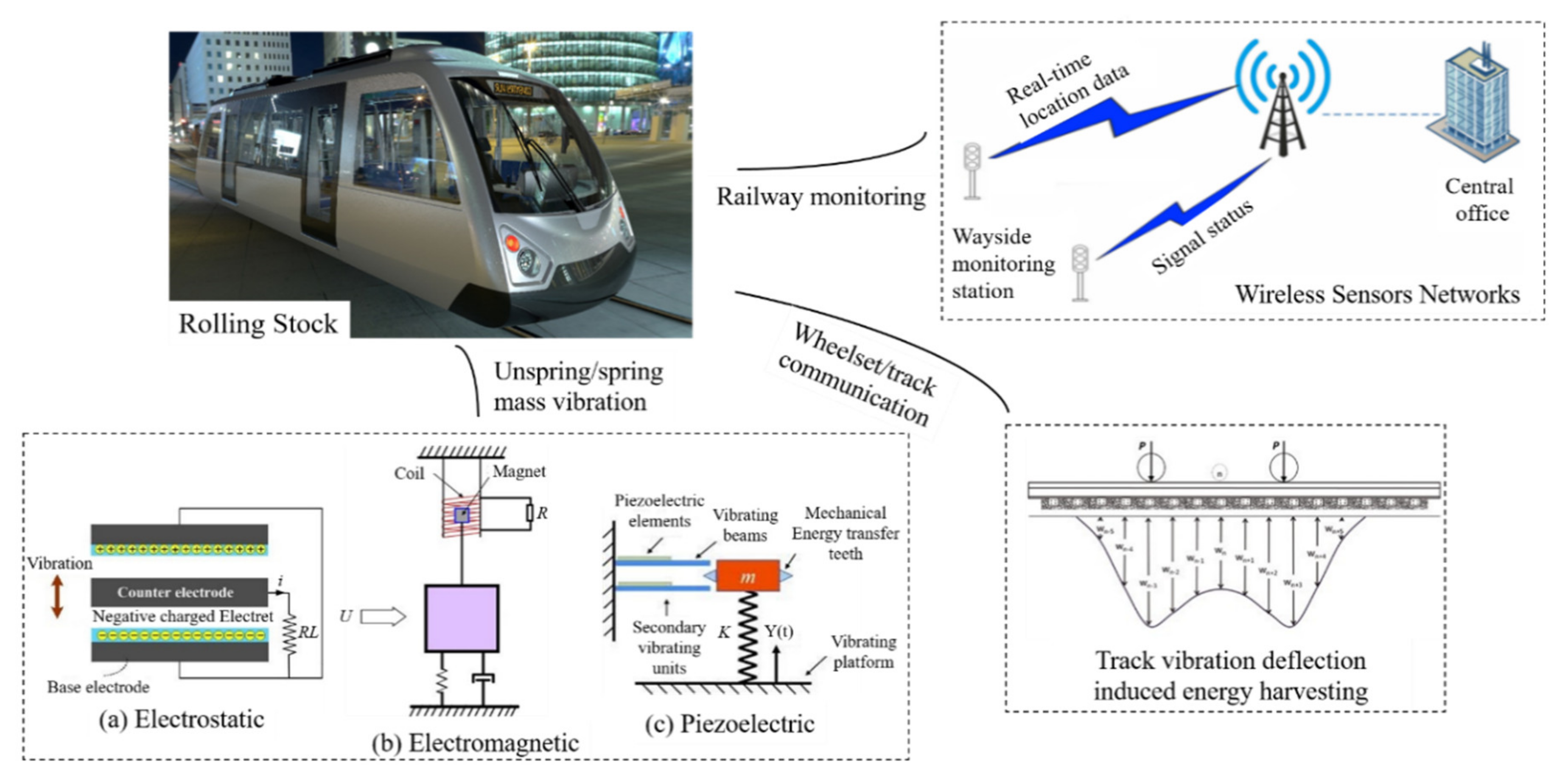
1. Introduction
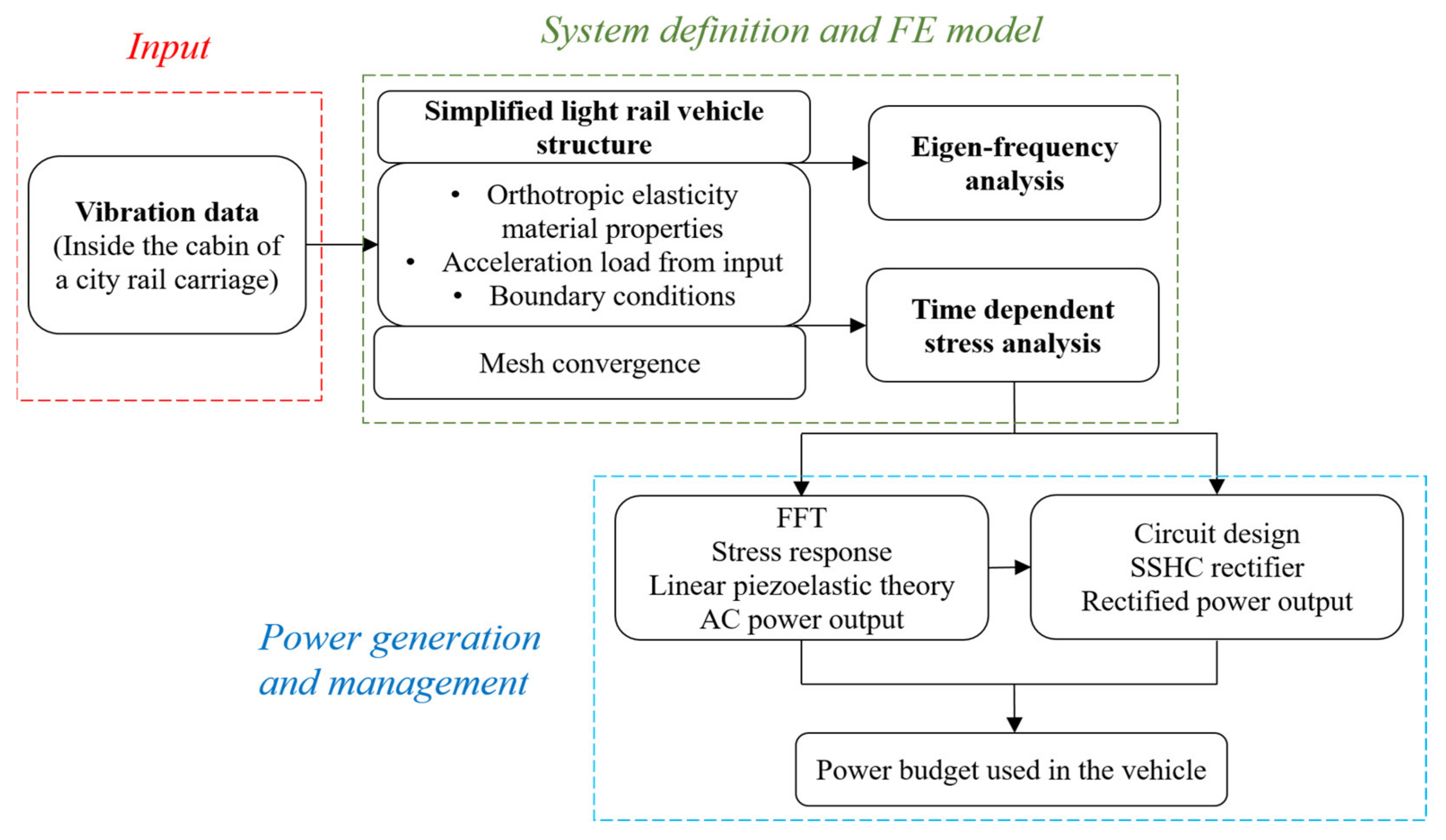
2. Finite Element Analysis of the Vehicle
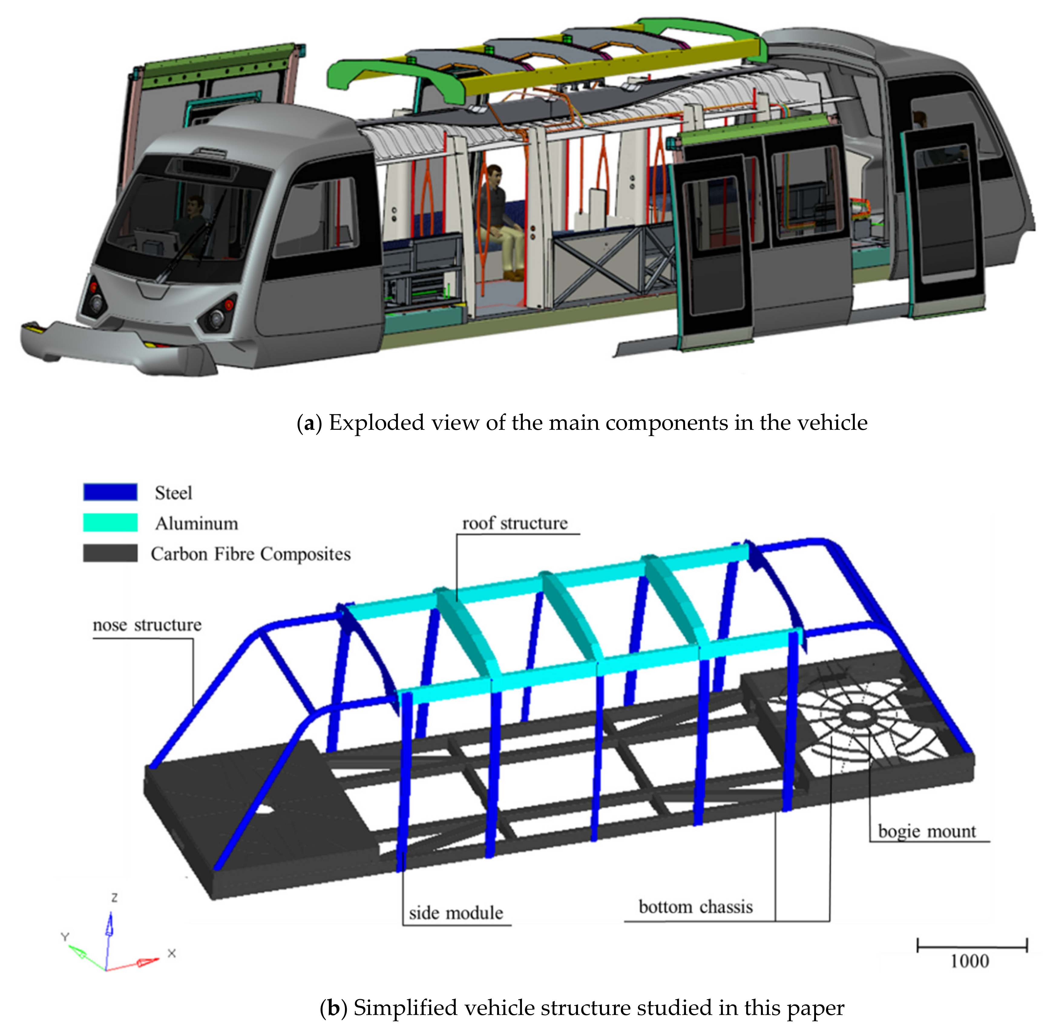
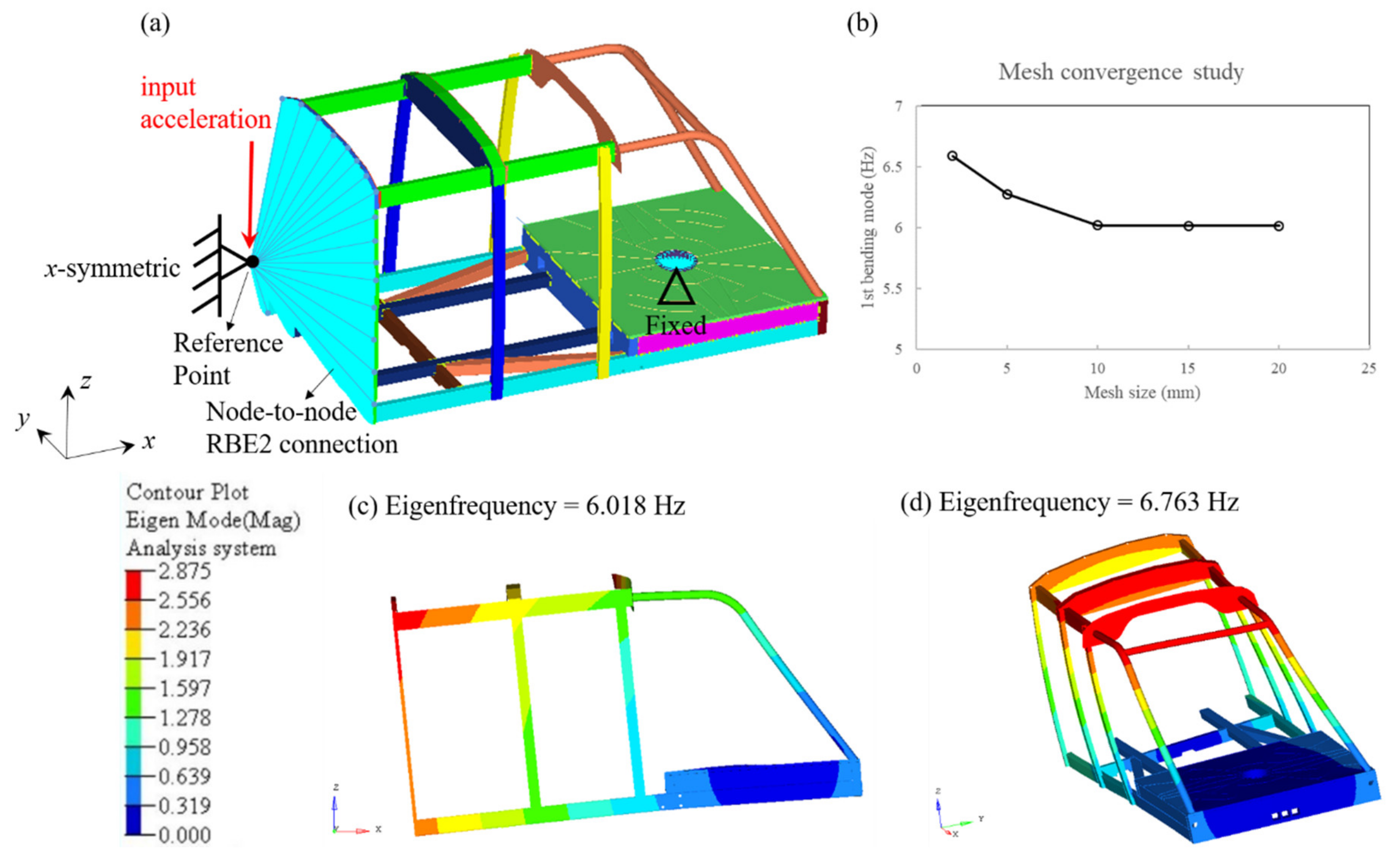
2.1. Finite Element Model
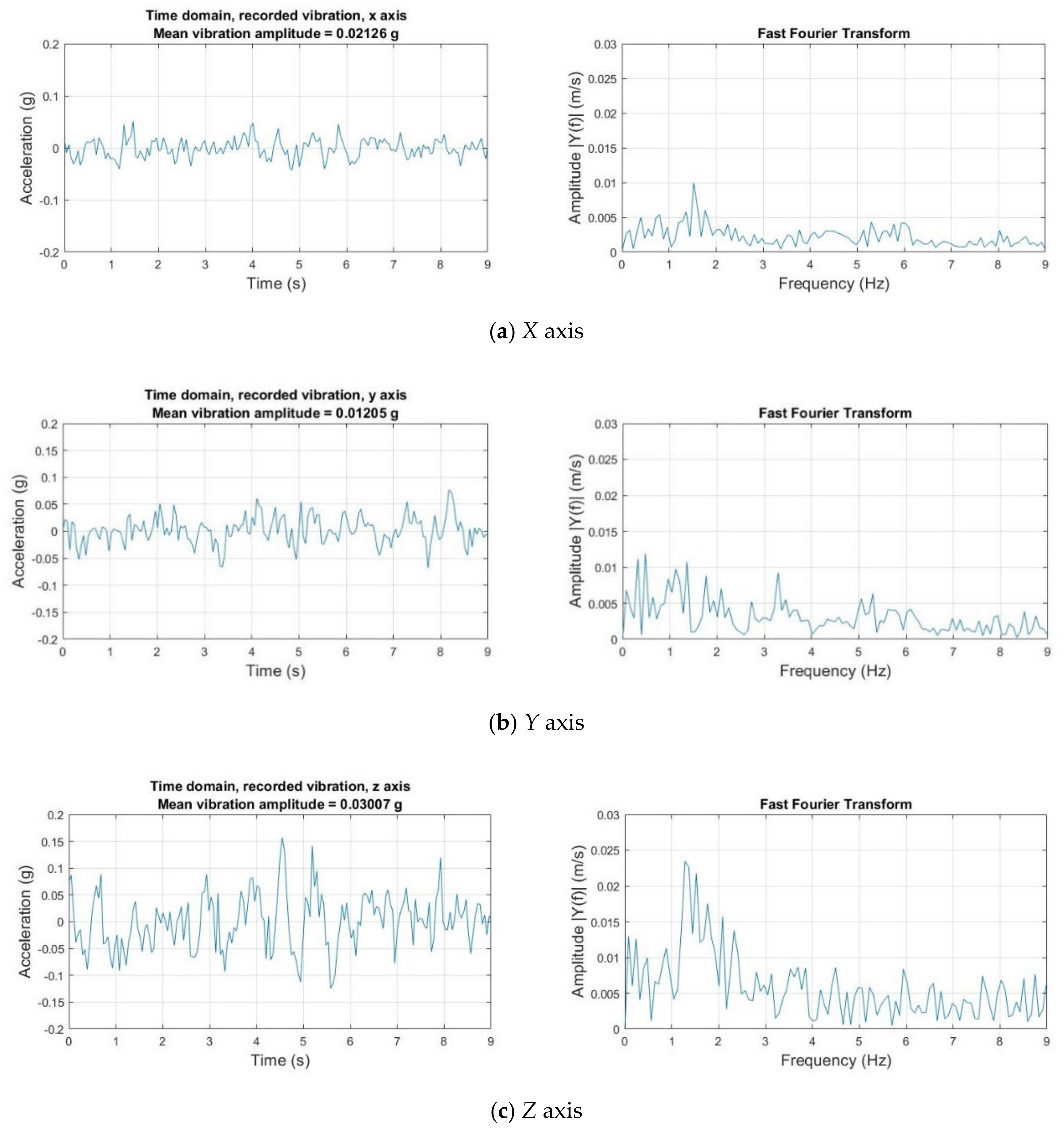
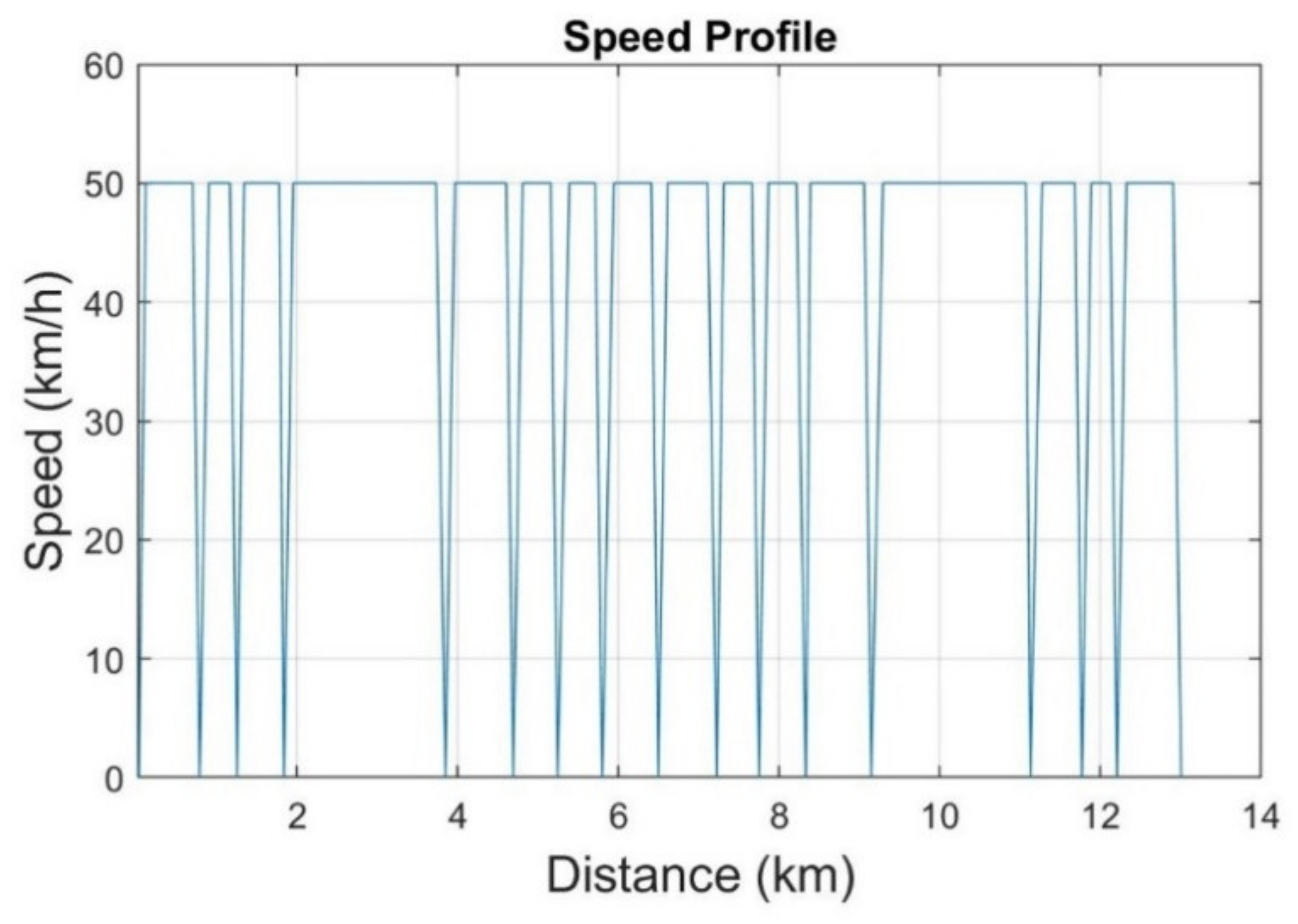
2.2. Vibration Data Analysis
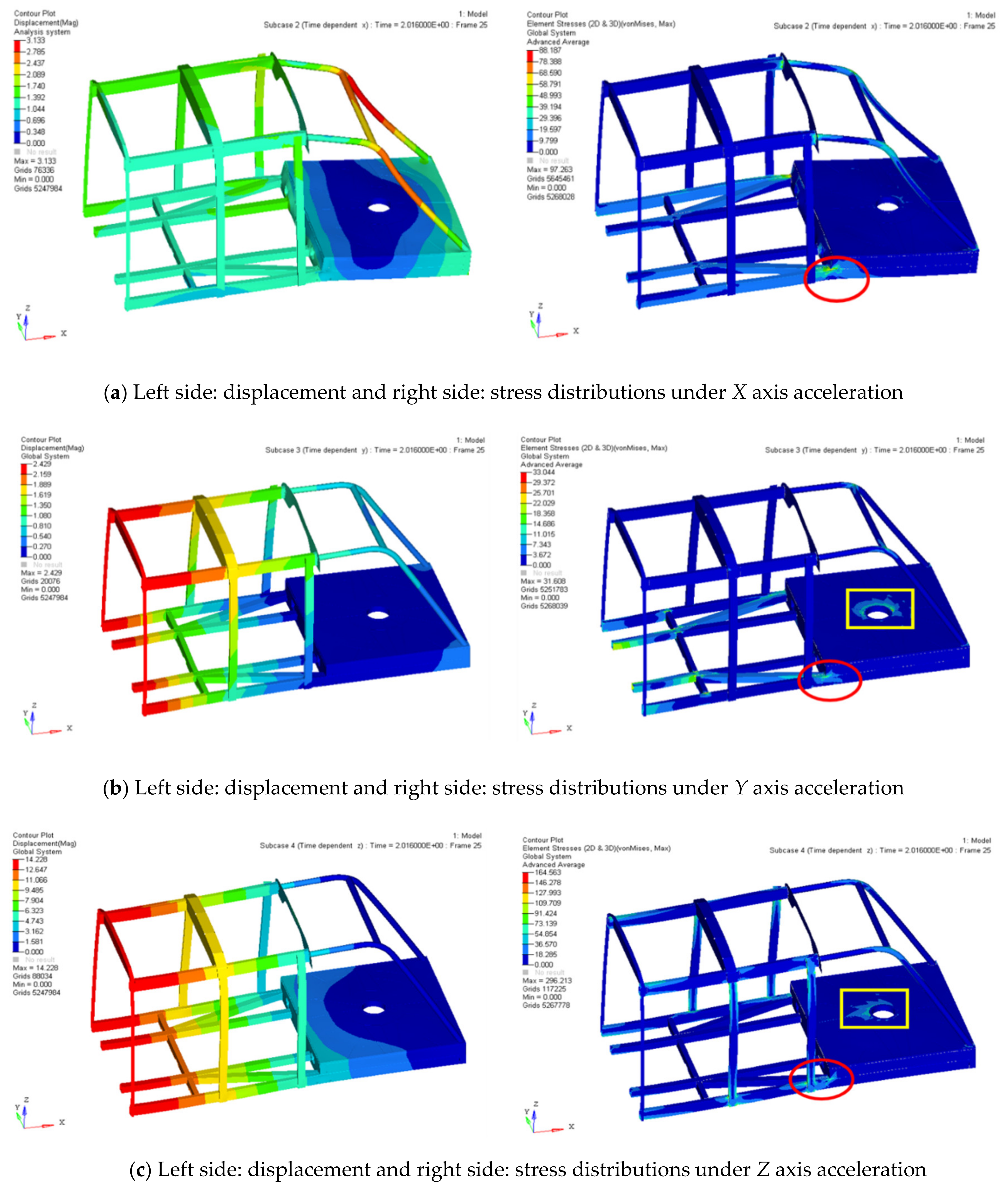
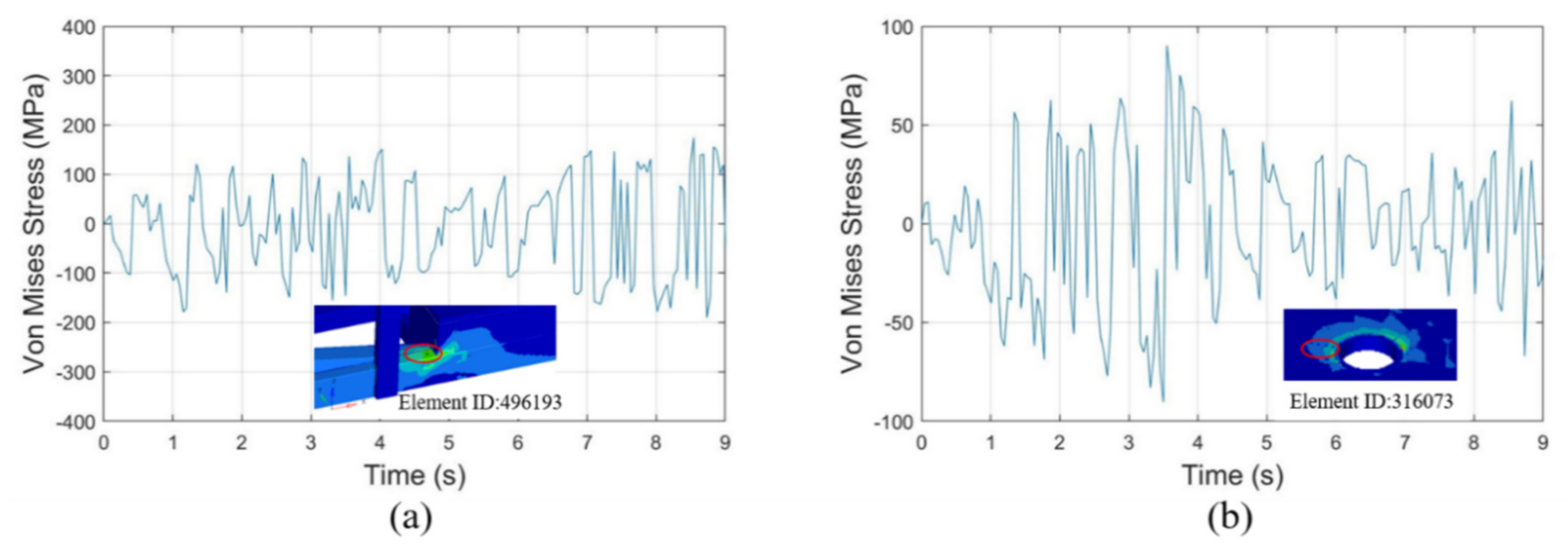
2.3. Stress Responses Used for Power Prediction
3. Power Generation and Management
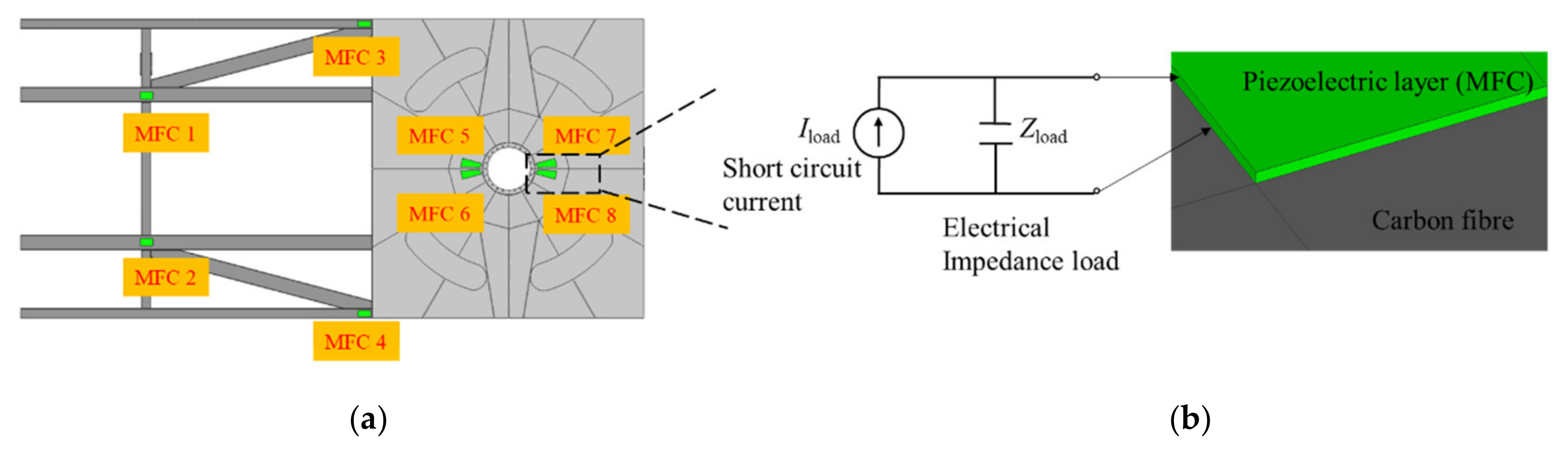
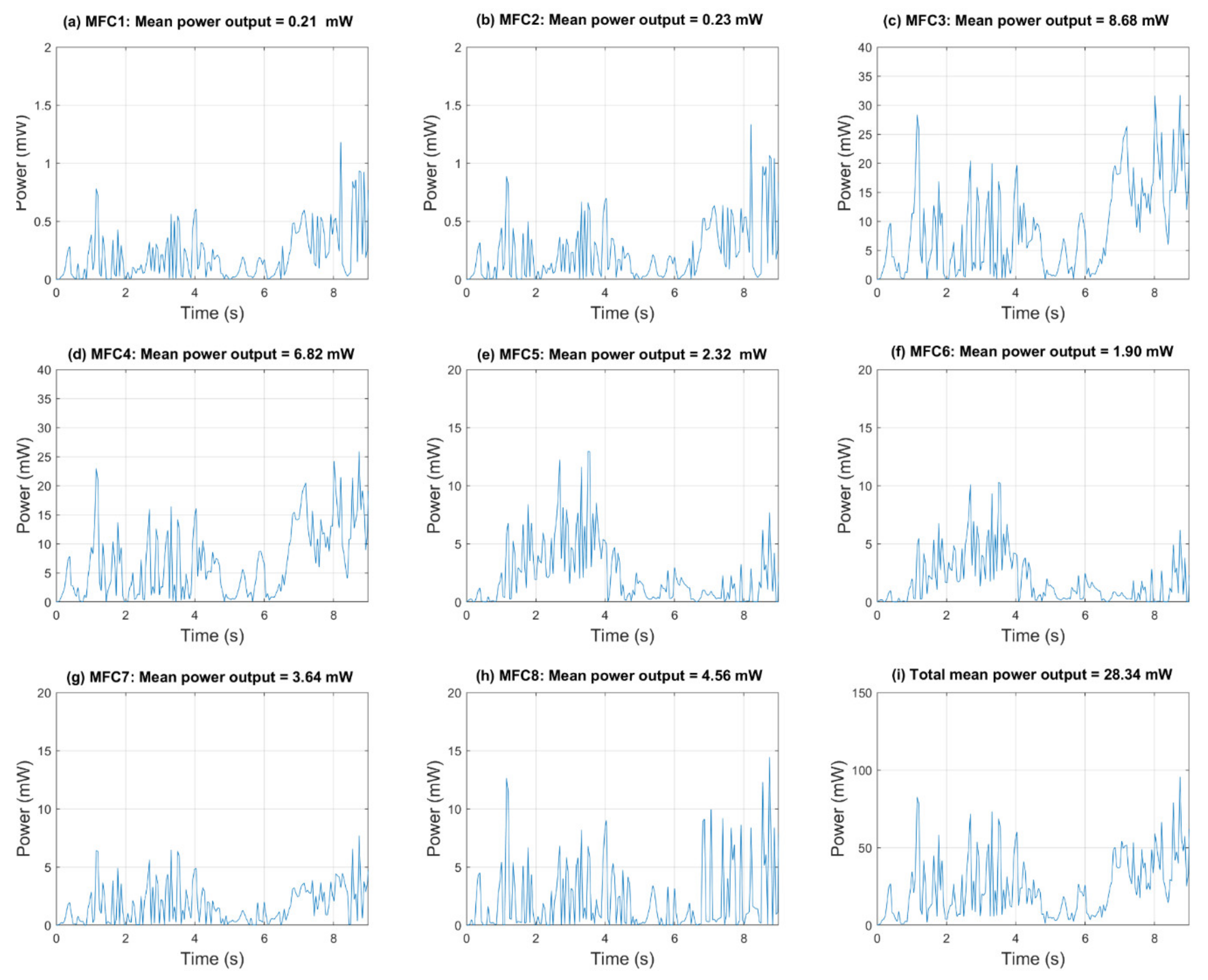
3.1. AC Power Prediction Using MFC Piezoelectric Material
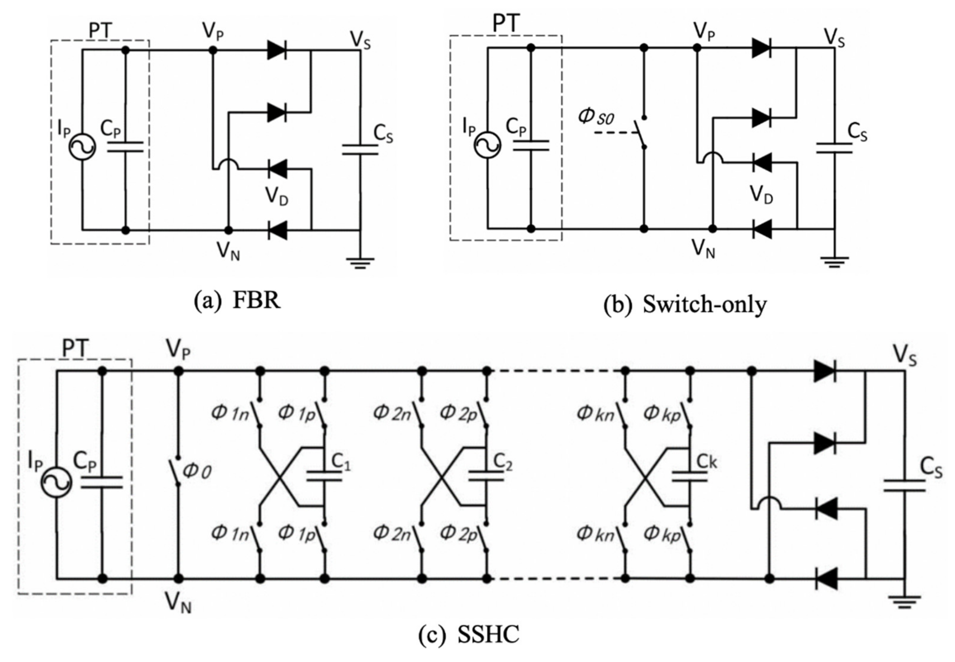
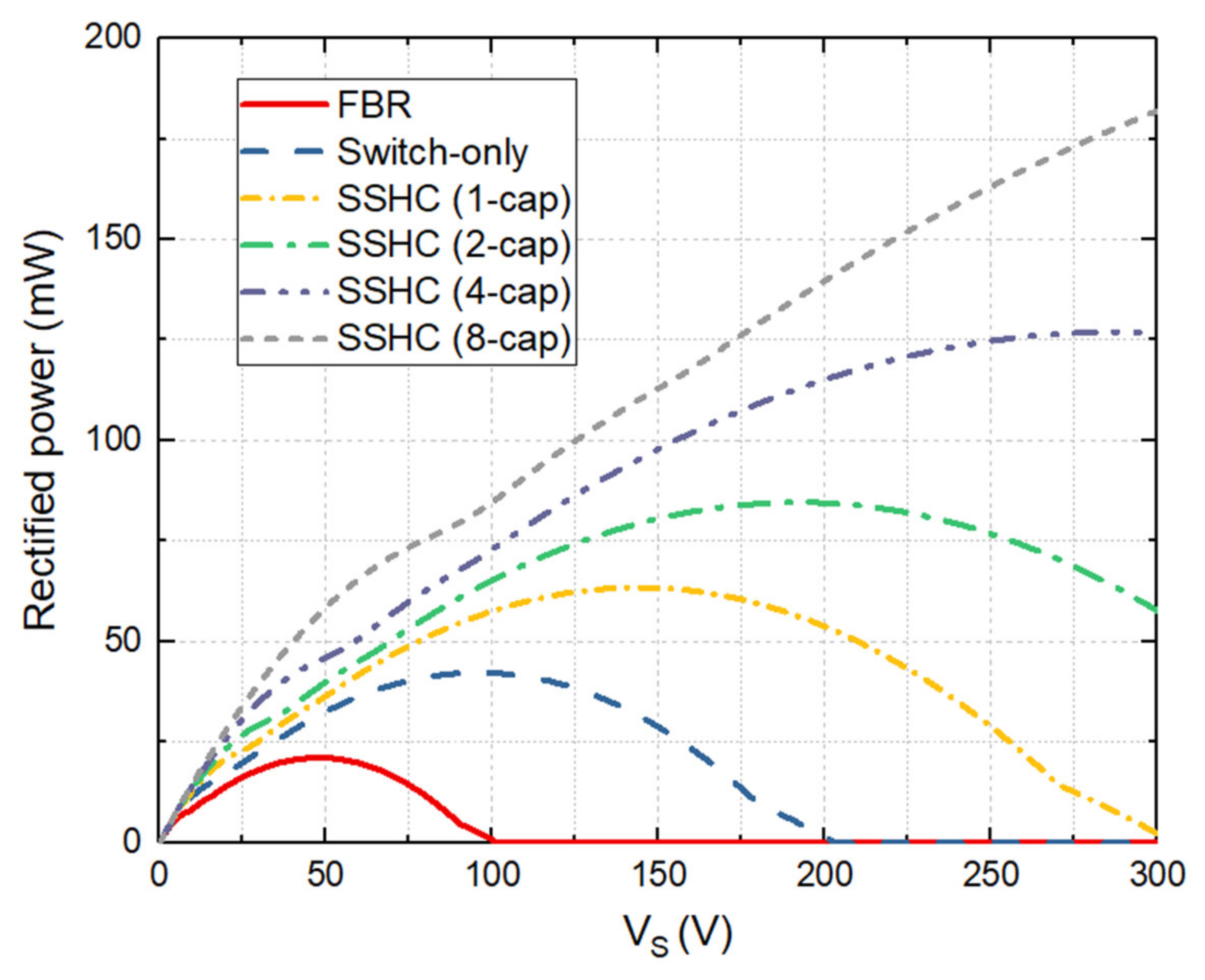
3.2. Rectified Power Prediction
4. Discussion on Use of Power Budget
5. Conclusions
Author Contributions
Funding
Acknowledgments
Conflicts of Interest
Abbreviations
| CFRP | carbon fiber reinforced polymer |
| FBR | full-bridge rectifiers |
| FEA | finite element analysis |
| MFC | micro fiber composites |
| SO | switch-only |
| SSHC | synchronized switch harvesting capacitors |
References
- Zuo, L.; Tang, X. Large-scale vibration energy harvesting. J. Intell. Mater. Syst. Struct. 2013, 24, 1405–1430. [Google Scholar] [CrossRef]
- Zuo, L.; Scully, B.; Shestani, J.; Zhou, Y. Design and characterization of an electromagnetic energy harvester for vehicle suspensions. Smart Mater. Struct. 2010, 19, 45003. [Google Scholar] [CrossRef]
- Glynne-Jones, P.; Tudor, J.; Beeby, S.P.; White, N. An electromagnetic, vibration-powered generator for intelligent sensor systems. Sens. Actuators A Phys. 2004, 110, 344–349. [Google Scholar] [CrossRef]
- Erturk, A.; Inman, D.J. A Brief Review of the Literature of Piezoelectric Energy Harvesting Circuits; Wiley: Hoboken, NJ, USA, 2011. [Google Scholar]
- Lu, Q.; Liu, L.; Scarpa, F.; Leng, J.; Liu, Y. A novel composite multi-layer piezoelectric energy harvester. Compos. Struct. 2018, 201, 121–130. [Google Scholar] [CrossRef]
- Jia, Y.; Yan, J.; Soga, K.; Seshia, A.A. Parametrically excited MEMS vibration energy harvesters with design approaches to overcome the initiation threshold amplitude. J. Micromech. Microeng. 2013, 23, 114007. [Google Scholar] [CrossRef]
- Zhu, G.; Chen, J.; Liu, Y.; Bai, P.; Zhou, Y.; Jing, Q.; Pan, C.; Wang, Z.L. Linear-Grating Triboelectric Generator Based on Sliding Electrification. Nano Lett. 2013, 13, 2282–2289. [Google Scholar] [CrossRef]
- Zhu, G.; Lin, Z.-H.; Jing, Q.; Bai, P.; Pan, C.; Yang, Y.; Zhou, Y.; Wang, Z.L. Toward Large-Scale Energy Harvesting by a Nanoparticle-Enhanced Triboelectric Nanogenerator. Nano Lett. 2013, 13, 847–853. [Google Scholar] [CrossRef]
- Lafont, T.; Gimeno, L.; Delamare, J.; A Lebedev, G.; I Zakharov, D.; Viala, B.; Cugat, O.; Galopin, N.; Garbuio, L.; Geoffroy, O. Magnetostrictive–piezoelectric composite structures for energy harvesting. J. Micromech. Microeng. 2012, 22, 94009. [Google Scholar] [CrossRef]
- Minsili, L.S.; Xia, H.; Eko, R.M. Analytical model of underground train induced vibrations on nearby building structures in Cameroon: Assessment and prediction. Leonardo Electron. J. Pract. Technol. 2013, 12, 63–82. [Google Scholar]
- Gill, K.S. Cognitive Radio Connectivity for Railwa Transportation Networkds. Master′s Thesis, Worcester Polytechnic Institute, Worcester, MA, USA, 2018. [Google Scholar]
- Tao, K.; Lye, S.W.; Miao, J.M.; Hu, X.M. Performance enhancement of an out-of-plane electret-based vibrational energy harvester with dual charged plates. J. Phys. Conf. Ser. 2014, 557, 012064. [Google Scholar] [CrossRef]
- Li, H.; Tian, C.; Deng, Z.D. Energy harvesting from low frequency applications using piezoelectric materials. Appl. Phys. Rev. 2014, 1, 041301. [Google Scholar] [CrossRef]
- Dai, H.L.; Abdelkefi, A.; Javed, U.; Wang, L. Modeling and performance of electromagnetic energy harvesting from galloping oscillations. Smart Mater. Struct. 2015, 24, 45012. [Google Scholar] [CrossRef]
- Gao, M.; Wang, P.; Cao, Y.; Chen, R.; Cai, D. Design and Verification of a Rail-Borne Energy Harvester for Powering Wireless Sensor Networks in the Railway Industry. IEEE Trans. Intell. Transp. Syst. 2016, 18, 1–14. [Google Scholar] [CrossRef]
- Al-Saadi, A.; Shi, Y.; Pan, L.; Tao, J.; Jia, Y. Vibration energy harvesting of multifunctional carbon fibre composite laminate structures. Compos. Sci. Technol. 2019, 178, 1–10. [Google Scholar] [CrossRef]
- Beeby, S.P.; Tudor, M.J.; White, N. Energy harvesting vibration sources for microsystems applications. Meas. Sci. Technol. 2006, 17, R175–R195. [Google Scholar] [CrossRef]
- Chen, J.; Wang, Z.L. Reviving Vibration Energy Harvesting and Self-Powered Sensing by a Triboelectric Nanogenerator. Joule 2017, 1, 480–521. [Google Scholar] [CrossRef]
- Sosnicki, O.; Lhermet, N.; Claeyssen, F. Vibration energy harvesting in aircraft using piezoelectric actuators. Proc. Actuator 2006, 21, 968–971. [Google Scholar]
- Shi, Y.; Hallett, S.; Zhu, M. Energy harvesting behaviour for aircraft composites structures using macro-fibre composite: Part I—Integration and experiment. Compos. Struct. 2017, 160, 1279–1286. [Google Scholar] [CrossRef]
- Tianchen, Y.; Jian, Y.; RuiGang, S.; Xiaowei, L. Vibration energy harvesting system for railroad safety based on running vehicles. Smart Mater. Struct. 2014, 23, 125046. [Google Scholar] [CrossRef]
- Pourghodrat, A.; Nelson, C.A.; E Hansen, S.; Kamarajugadda, V.; Platt, S.R. Power harvesting systems design for railroad safety. Proc. Inst. Mech. Eng. Part F J. Rail Rapid Transit 2013, 228, 504–521. [Google Scholar] [CrossRef]
- Hadas, Z.; Smilek, J.; Rubes, O. Energy harvesting from passing train as source of energy for autonomous trackside objects. MATEC Web Conf. 2018, 211, 05003. [Google Scholar] [CrossRef][Green Version]
- Du, S.; Jia, Y.; Arroyo, E.; Fernandez, S.; Riches, S.T.; Seshia, A.A. MEMS Piezoelectric Energy Harvester Powered Wireless Sensor Module Driven by Noisy Base Excitation. In Proceedings of the 2019 20th International Conference on Solid-State Sensors, Actuators and Microsystems & Eurosensors XXXIII (TRANSDUCERS & EUROSENSORS XXXIII), Berlin, Germany, 23–27 June 2019; pp. 350–353. [Google Scholar]
- Jia, Y.; Yan, J.; Du, S.; Feng, T.; Fidler, P.; Middleton, C.; Soga, K.; Seshia, A.A. Real world assessment of an auto-parametric electromagnetic vibration energy harvester. J. Intell. Mater. Syst. Struct. 2017, 29, 1481–1499. [Google Scholar] [CrossRef]
- Du, S.; Jia, Y.; Zhao, C.; Chen, S.-T.; Seshia, A.A. Real-world evaluation of a self-startup SSHI rectifier for piezoelectric vibration energy harvesting. Sens. Actuators A Phys. 2017, 264, 180–187. [Google Scholar] [CrossRef]
- Erturk, A.; Inman, D.J. An experimentally validated bimorph cantilever model for piezoelectric energy harvesting from base excitations. Smart Mater. Struct. 2009, 18, 25009. [Google Scholar] [CrossRef]
- Erturk, A.; Inman, D.J. A Distributed Parameter Electromechanical Model for Cantilevered Piezoelectric Energy Harvesters. J. Vib. Acoust. 2008, 130, 041002. [Google Scholar] [CrossRef]
- Jia, Y.; Wei, X.; Xu, L.; Wang, C.; Lian, P.; Xue, S.; Al-Saadi, A.; Shi, Y. Multiphysics vibration FE model of piezoelectric macro fibre composite on carbon fibre composite structures. Compos. Part B Eng. 2019, 161, 376–385. [Google Scholar] [CrossRef]
- Winnett, J.; Hoffrichter, A.; Iraklis, A.; McGordon, A.; Hughes, D.J.; Ridler, T.; Mallinson, N. Development of a very light rail vehicle. Proc. Inst. Civ. Eng. Transp. 2017, 170, 231–242. [Google Scholar] [CrossRef]
- Gulf Coast Data Concepts. X16-1D USB MEMS Accelerometer Data Loggers. 2016. Available online: http://www.gcdataconcepts.com/xlr8r-1.html (accessed on 25 May 2020).
- Prepreg Fabric—GURIT SE84LV/RC200T/42%. Available online: https://www.900gpa.com/en/product/prepregCompound/FabPreg_00FABBBA10?u=metric (accessed on 16 October 2019).
- Microfibre Composites (MFC) P2, P3 Type. Smart Compos n.d. Available online: https://www.smart-material.com/MFC-product-P2.html (accessed on 15 October 2019).
- Du, S.; Jia, Y.; Zhao, C.; Amaratunga, G.A.J.; Seshia, A.A. A Passive Design Scheme to Increase the Rectified Power of Piezoelectric Energy Harvesters. IEEE Trans. Ind. Electron. 2018, 65, 7095–7105. [Google Scholar] [CrossRef]
- Du, S.; Jia, Y.; Zhao, C.; Amaratunga, G.A.J.; Seshia, A.A. A Fully Integrated Split-Electrode SSHC Rectifier for Piezoelectric Energy Harvesting. IEEE J. Solid-State Circuits 2019, 54, 1733–1743. [Google Scholar] [CrossRef]
- Wang, J.J.; Penamalli, G.P.; Zuo, L. Electromagnetic energy harvesting from train induced railway track vibrations. In Proceedings of the 2012 IEEE/ASME 8th IEEE/ASME International Conference on Mechatronic and Embedded Systems and Applications, Suzhou, China, 8–10 July 2012; Volume 11787, pp. 29–34. [Google Scholar] [CrossRef]
- Wang, J.; Shi, Z.; Xiang, H.-J.; Song, G. Modeling on energy harvesting from a railway system using piezoelectric transducers. Smart Mater. Struct. 2015, 24, 105017. [Google Scholar] [CrossRef]
- Cleante, V.G.; Brennan, M.J.; Gatti, G.; Thompson, D.J. Energy harvesting from the vibrations of a passing train: Effect of speed variability. J. Phys. Conf. Ser. 2016, 744, 12080. [Google Scholar] [CrossRef]
- Tehrani, M.G.; Gatti, G.; Brennan, M.J.; Thompson, D.J.; Oscillator, L. Energy harvesting from train vibrations. In Proceedings of the 11th International Conference on Vibration Problems, Lisbon, Portugal, 8–11 September 2013; pp. 9–12. [Google Scholar]
- Wheelwright, H.E.; Vincent, D. Track defect and wheel damage: Detection and location. Perpetuum Ltd. Available online: https://perpetuum.com/download/track-defect-and-wheel-damage-detection-and-location (accessed on 25 May 2020).
- Jiang, B.Y.; Liu, J.; Tian, W.; Shahidehpour, M.; Krishnamurthy, M. Energy harvesting for the electrification of railway stations. IEEE Electrif. Mag. 2014, 2, 39–48. [Google Scholar] [CrossRef]
- TDK-InvenSense. MPU-9250 Nine-Axis (Gyro + Accelerom + Compass) MEMS Motion Trackin Device n.d. Available online: https://www.invensense.com/products/motion-tracking/9-axis/mpu-9250/ (accessed on 25 October 2019).
- SCA100T Inclinometers | Inclinometers | Sensors | Murata Manufacturing Co., Ltd. Available online: https://www.murata.com/en-sg/products/sensor/inclinometer/sca100t (accessed on 23 October 2019).
- SRF08 Ultrasonic Sensor n.d. Available online: https://www.active-robots.com/srf08-ultrasonic-sensor.html (accessed on 23 October 2019).
- STM32L4-ARM Cortex-M4 ultra-low-power MCUs-STMicroelectronics. Available online: https://www.st.com/en/microcontrollers-microprocessors/stm32l4-series.html (accessed on 23 October 2019).
- Darroudi, S.M.; Caldera-Sànchez, R.; Gomez, C. Bluetooth Mesh Energy Consumption: A Model. Sensors 2019, 19, 1238. [Google Scholar] [CrossRef] [PubMed]
- Jia, Y. Review of nonlinear vibration energy harvesting: Duffing, bistability, parametric, stochastic and others. J. Intell. Mater. Syst. Struct. 2020, 31, 921–944. [Google Scholar] [CrossRef]


| Elastic Modulus (GPa) | Poisson’s Ratio | Density (kg/m3) | |
|---|---|---|---|
| Steel | 210 | 0.29 | 7850 |
| Aluminium | 69 | 0.3 | 2700 |
| CFRP (RC200T) [29] | Ex = 59.45, Ey = 60.30, Ez = 3.90 Gxy = 62.90, Gyz = 1.50, Gxz = 62.35 | υxy = 0.3 υyz = 0.4 υxz = 0.3 | 1800 |
| Mode | Freq. (Hz) |
|---|---|
| 1st bending (Figure 4b) | 6.018 |
| 2nd bending | 19.935 |
| 1st torsional (Figure 4c) | 6.763 |
| 2nd torsional | 14.407 |
| 3rd torsional | 21.921 |
| 1st lateral | 23.839 |
| Ex (GPa) | Ey (GPa) | Gxy (GPa) | νxy | Density (kg/m3) |
|---|---|---|---|---|
| 30.34 | 15.86 | 5.52 | 0.31 | 5400 |
| Charge Constant d31 (pC/N) | −170 |
| Charge constant d33 (pC/N) | 400 |
| Capacitance per unit area Cp (nF/cm2) | 7.8 |
| Dielectric permittivity εp | 0.15 |
| Rectifiers | Peak Power (mW) | Optimal VS (V) |
|---|---|---|
| FBR | 21.2 | 48 |
| Switch-only | 42.3 | 96 |
| SSHC (1-cap) | 63.4 | 144 |
| SSHC (2-cap) | 84.6 | 192 |
| SSHC (4-cap) | 126.9 | 288 |
| SSHC (8-cap) | 181.9 | 300 |
| Peak Rectified Power (mW) | Percentage (%) | ||||||
|---|---|---|---|---|---|---|---|
| MFC No. | FBR | Switch-only | SSHC (1-cap) | SSHC (2-cap) | SSHC (4-cap) | SSHC (8-cap) | |
| 1 | 0.28 | 0.56 | 0.84 | 1.12 | 1.68 | 2.79 | 1.2 |
| 2 | 0.31 | 0.61 | 0.92 | 1.23 | 1.84 | 3.06 | 1.3 |
| 3 | 11.89 | 23.78 | 35.67 | 47.57 | 71.35 | 118.92 | 51.7 |
| 4 | 9.34 | 18.68 | 28.01 | 37.35 | 56.03 | 93.38 | 40.6 |
| 5 | 0.24 | 0.47 | 0.71 | 0.94 | 1.41 | 2.36 | 1.0 |
| 6 | 0.19 | 0.39 | 0.58 | 0.77 | 1.16 | 1.94 | 0.8 |
| 7 | 0.35 | 0.69 | 1.04 | 1.38 | 2.07 | 3.46 | 1.5 |
| 8 | 0.41 | 0.82 | 1.22 | 1.63 | 2.45 | 4.08 | 1.8 |
| Power Budget Item | Power (mW) | Active in Period (%) | Active Time in One Route Cycle (s) | Power in One Route Cycle (mW) |
|---|---|---|---|---|
| MEMS 9 DOF motion sensor + MPU [42] × 2 units | 0.05 | 100% | 1200 | 1 |
| Inclinometers [43] × 2 units | 56.25 | 100% | 1200 | 112.50 |
| Distance sensors [44] × 2 units | 13.95 | 100% | 1200 | 27.90 |
| Microprocessor unit (MPU) (active mode [45]) × 2 units | 0.36 | 100% | 1200 | 0.72 |
| Bluetooth 5 + RF chip (transceiver mode [46]) × 2 units | 27 | 20% | 240 | 10.80 |
| Bluetooth 5 + RF chip (sleep mode, clock [46]) × 2 units | 0.045 | 80% | 960 | 0.08 |
| Sum | 153.00 | |||
| Type of Rail Harvesting | Energy Harvest | Methodology | Comments |
|---|---|---|---|
| Train induced track vibration | 2–4 V | Experiments | For 6.35 mm track displacement input, from Wang et al. [36] |
| 0.02–0.2 mW | Experiments Analytical modelling | For slack-type and patch-type piezoelectric transducers, from Wang et al. [37] | |
| 100.3–157.1 mW | Analytical modelling | With passing train speed from 190 to 200 km/h, from Cleante et al. [38] | |
| Electrification of railway stations | 541.6 kW | Electronics simulation | Jiang et al. [41] |
| Unsprung mass vibration | 21.4 mW | Analytical modelling | Ghandchi Tehrani et al. [39] |
| 1–5 wheel health index | Experiments | Wheelwright et al. [40] | |
| Sprung mass vibration | 21.2–181.9 mW | Finite element modelling Electronics simulation | This work |
© 2020 by the authors. Licensee MDPI, Basel, Switzerland. This article is an open access article distributed under the terms and conditions of the Creative Commons Attribution (CC BY) license (http://creativecommons.org/licenses/by/4.0/).
Share and Cite
Liu, Y.; Du, S.; Micallef, C.; Jia, Y.; Shi, Y.; Hughes, D.J. Optimisation and Management of Energy Generated by a Multifunctional MFC-Integrated Composite Chassis for Rail Vehicles. Energies 2020, 13, 2720. https://doi.org/10.3390/en13112720
Liu Y, Du S, Micallef C, Jia Y, Shi Y, Hughes DJ. Optimisation and Management of Energy Generated by a Multifunctional MFC-Integrated Composite Chassis for Rail Vehicles. Energies. 2020; 13(11):2720. https://doi.org/10.3390/en13112720
Chicago/Turabian StyleLiu, Yiding, Sijun Du, Christopher Micallef, Yu Jia, Yu Shi, and Darren J. Hughes. 2020. "Optimisation and Management of Energy Generated by a Multifunctional MFC-Integrated Composite Chassis for Rail Vehicles" Energies 13, no. 11: 2720. https://doi.org/10.3390/en13112720
APA StyleLiu, Y., Du, S., Micallef, C., Jia, Y., Shi, Y., & Hughes, D. J. (2020). Optimisation and Management of Energy Generated by a Multifunctional MFC-Integrated Composite Chassis for Rail Vehicles. Energies, 13(11), 2720. https://doi.org/10.3390/en13112720