Abstract
Multiphase drives are entering the spotlight of the research community for transportation applications with their high power density and the possibility of high fault tolerance. The multi three-phase drive is one of the main types of multiphase drives that allows for the direct adoption of commercial three-phase converters and high control flexibility. The elimination of high-frequency current harmonics will reduce the flux linkage harmonics, torque ripple, vibration and noise in machine drives. Therefore, this work introduces a new method to the modelling of equivalent phase current in multi three-phase drives with the double integral Fourier analysis method. A new carrier-based pulse-width modulation (CPWM) method is introduced to reduce the equivalent phase current harmonics by applying proper carrier phase angle to each subsystem in the multi three-phase drives. The proposed angles of carrier signals are analyzed for quadruple three-phase drives, and the corresponding experimental results confirm the significance of the proposed phase-shifted CPWM method to eliminate the equivalent phase current harmonics.
1. Introduction
Three-phase machines were universally used at the beginning of the 20th century as they present better torque performance compared with the single-phase and the two-phase machines, which produce the twice pulsating torque ripple [1]. The increasing phase number of the machine will not produce the twice-pulsating torque ripple. The development of power electronics in the 1980s enabled the adoption of machines with more than three phases. The machine can be connected to the power converters rather than directly connected to the three-phase power supply. Therefore, an arbitrary phase machine can be used as long as the phase number of the machine matches the phase number of the power converter, especially for the application of electric propulsion [2,3,4,5]. There are several reasons why the multiphase machine attracts a wide range of interest in the research community. Firstly, the multiphase machine has good fault tolerance performance compared with the conventional three-phase machine [6,7]. Taking a 15-phase machine as an example, the machine can be operated at over 90% of the rated power with the breakdown of one phase. Secondly, the adoption of a multiphase machine greatly reduces the voltage sharing on power converters of each phase leg, which offers the feasibility of the multiphase machine used for high-power applications [8,9,10,11,12]. Additionally, the control of a multiphase drive system becomes more flexible, which gives a possibility to cancel the time-domain harmonics and space-domain harmonics in the drive system. Therefore, the efficiency and torque performance in the multiphase is improved with respect to the traditional single three-phase drives [13,14,15].
Recently, multi three-phase machines with separate neutral points controlled by parallel converters have become an increasing concern, which is shown in Figure 1 [8,16]. The adoption of parallel converters make it possible to control very high-power and high-speed machines with commercial products, since the power requirement on each inverter module is reduced. Moreover, this topology has high fault tolerance, as any inverter module is independent without any electrical connections to the other modules [6]. Besides, the adoption of the parallel converters increases the flexibility of the control algorithm. The torque ripple, noise and vibration of the machine, and the direct current (dc) link voltage ripple are possibly to be reduced by applying a proper control scheme [17,18].
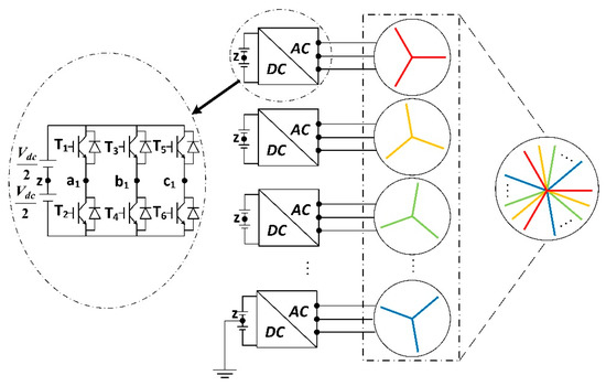
Figure 1.
Multi three-phase drives system.
The carrier-based pulse width modulation (CPWM) is known as the earliest and most straightforward modulation technique [19]. The working principle of the CPWM is to compare the fundamental signal with the carrier signal (high frequency) to determine the states of switching devices on power converters. When the fundamental waveform is lower than the carrier with waveform, the switch at the bottom of the converter leg (T2 T4 and T6 in Figure 1) will turn on; when the fundamental waveform is larger than the carrier waveform, the switch on the top of the converter leg (T1 T3 and T5 in Figure 1) will turn on. Compared with the space vector modulation, the CPWM has lower dc link voltage utilization [20]. This drawback can be avoided by the injection of the zero-sequence harmonics [21]. The implementation of CPWM is straightforward and it can be extended to the control of the multiphase multilevel converters without greatly increasing the complexity of the control algorithm. The phase-shifted CPWM is the commonly used CPWM for the control of multilevel converters, as it has the same switching frequency and conducting periods, which means even power distribution on the power switches of the converter [22,23]. Recent research works have verified that the pulse width modulation (PWM) technique results in high-frequency torque ripple in multiphase drives [24,25]. For instance, [25] shows that the high-frequency torque harmonics are mitigated by choosing appropriate carrier angles in dual three-phase drive systems. The high-frequency PWM-related current harmonics are known as the source of the high-frequency flux linkage harmonics, torque ripple, vibration and noise [26,27]. Therefore, it is of importance to reduce the equivalent current harmonics of the multiphase drive systems by considering the effect the CPWM technique.
This article exploits the degrees of control freedom in multi three-phase drives, by applying the concept phase-shifted CPWM to multi three-phase drives to reduce total equivalent current harmonics. The remaining part of the article includes the following sections: Section 2 introduces the double Fourier integral analysis method of pulse width modulation. Section 3 presents the mathematical modelling of the equivalent current harmonics in multi three-phase drives. Section 4 shows the comparative experiment with and without applying the proposed phase-shift CPWM. Section 5 draws the conclusion of this article.
2. Double Fourier Integral Analysis Method of Pulse Width Modulation
According to [19], if the function of both and are periodic functions, the function is the summation of sinusoidal harmonics. Assuming the periods of both the functions and are , and is represented by:
with:
where m and n are the positive integer numbers.
Sine-triangle modulation is one of the most commonly used CPWMs. Figure 2 describes the x-y plane of the sine-triangle modulation, which is represented by . The blue area represents the parts when the switch at the top of the converter leg is turned on, while the white area represents the parts when the switch at the bottom of the converter leg is turned on [28]. The x and y axes are considered as the carrier signal and the modulating signal time-varying angles respectively. is described with the straight line in Figure 2a. The slope of is the quotient between the frequencies of the modulating waveform and the carrier waveform. The intersection points between the function and the changing boundaries of the function are the switching time instants of the converter. The corresponding pulse width modulation (PWM) output voltage waveform (from to ) is shown in Figure 2b.
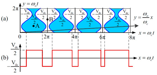
Figure 2.
(a) The x-y plane for the sine-triangle modulation (b) The x-y plane for the corresponding pulse width modulation (PWM) output voltage [28].
The time varying modulating signal can be presented as:
with respect to Equation (4), the intersection points in Figure 2a can be given as the following two cases. Case 1: for the function switches from to , the switching instants happens at:
Case 2: for the function converts from to , the switching time happens at:
The switching time instants in Equations (5) and (6) are the upper and the lower integral limits in Equations (2) and (3), respectively. The function of between the upper and the lower limits. Substituting Equations (5) and (6) into Equations (2) and (3), and can be rewritten as:
Substituting Equations (7) and (8) to Equation (1), and replacing and with and respectively, the time-varying output voltage of terminal a with respect to the ground in Figure 2 can be represented by the function of , which can be expressed as:
By using the double Fourier integral method, the time-varying phase leg voltage of can be expressed with the addition of the dc offset, the fundamental component and all of the sinusoidal harmonic components (carrier harmonics and sideband harmonics).
3. Modelling of Equivalent Current Harmonics in Multi Three-Phase Drives
According to Equation (9), assuming the modulating signal start angle as the reference (), the phase leg voltage (phase leg voltage is defined as the voltage drop between a, b, c and z, which is displayed in Figure 1) of the , three-phase subsystem (phase a) is represented as:
with:
where is the carrier phase angle in the three-phase subsystem and is the three-phase subsystem carrier phase start angle (). Referring to Equation (10), the equivalent phase voltage generated by all the subsystems (shown in Figure 1) can be represented as:
As can be seen from Equation (13), the total equivalent harmonic voltage will be decreased with different carrier angles in different three-phase systems. Applying to each three-phase system, the multi three-phase drive system will gain an effective switching frequency of . With the proposed phase-shifted CPWM in each three-phase drive, the total equivalent phase voltage is expressed by Equation (14):
Comparing Equations (13) and (14), the equivalent voltage harmonic components are significantly mitigated, while the remaining harmonics only exist around the multiples of .
Figure 3 shows the Fast Fourier Transformation (FFT) spectra of total equivalent voltage applying the phase-shifted CPWM with normalized with three modulation indexes (, , and ). In Figure 3, the total equivalent voltage is supplied to the machine with the same rated power for any number of split three-phase systems, which means the fundamental voltage components are the same for different values of . Figure 3 presents the FFT spectra of the total equivalent voltage without the proposed CPWM (for any number of split three-phase systems) at the layer of . Conforming to Equation (13), the total equivalent voltage is combined with the fundamental component and the groups of harmonics around the multiples of switching frequency. Figure 3 displays the FFT spectra of total equivalent voltage with proposed CPWM at the layers of . Consistent with Equation (14), the equivalent voltage harmonic components are significantly mitigated, while the only remaining harmonics exist at . The larger value of will result in higher order remaining harmonics, and thus the effect of total equivalent voltage harmonics cancellation is more dominant with the increasing value of subsystem number . Comparing Figure 3a–c, it can be observed that a different modulation index affects the harmonic amplitudes to a different extent. However, the same groups of the harmonic components will be eliminated despite the modulation indexes, and thus the proposed phase-shifted CPWM method can be applied into different working conditions. Taking the case as an example, with phase-shifted CPWM, the equivalent voltage harmonics around , , , , , , , are cancelled out under all the modulation indexes.
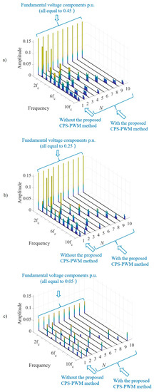
Figure 3.
Multi three-phase drive FFT spectra with and without the proposed phase-shifted carrier-based pulse-width modulation (CPWM) under different . (a) , (b), (c) .
In [24], it indicates that the relationship between voltage harmonics and current harmonics can be drawn as:
where is the impedance of the hth harmonic component. According to Equations (13) and (14), the equivalent phase current can be represented as:
Applying the proposed phase-shifted CPWM in each three-phase system, the equivalent phase current can be represented as:
Referring to Equations (14) and (17), it is concluded that applying the proposed phase-shifted CPWM will effectively reduce the equivalent voltage harmonics as well as their corresponding current harmonics.
4. Experimental Results
A quadruple three-phase permanent magnet synchronous machine driven by quadruple independent three-phase modular inverters platform was set up in the laboratory, which is shown in Figure 4, to validate the proposed phase-shifted CPWM method analyzed in Section 3. The PLECS RT lab box is set as a real time controller to generate synchronized gate signals to drive the quadruple three-phase modular converters. The control strategy of this experimental test consists of two closed loops (i.e., the outer speed loop and inner current loop with proportional-integral (PI) controllers). The main experimental parameters are shown in Table 1. In order to better show the PWM harmonics, the fundamental components in Figure 5 and Figure 6 are saturated.
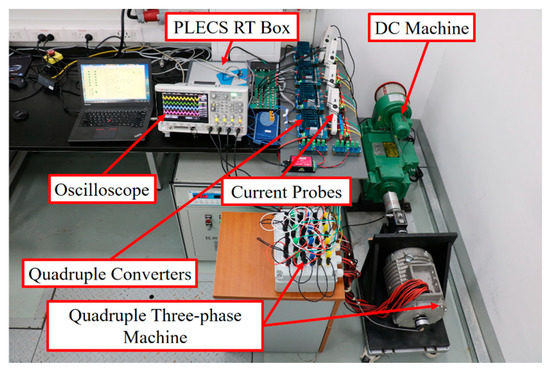
Figure 4.
Quadruple three-phase drive system experimental setup.

Table 1.
Experimental parameters.
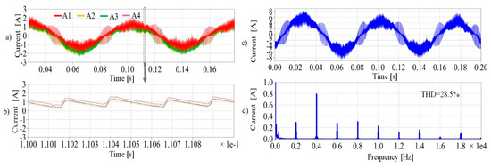
The phase currents experimental results without the proposed phase-shift CPWM are displayed in Figure 5. The carrier phase angles in each subsystem were set to be . Figure 5a shows the time-varying current waveforms (phase A) from all the four subsystems, while Figure 5b shows the cursor range of Figure 5a, which is the two-period range of the carrier signal. Figure 5a,b show that the phase currents are in phase in terms of both modulating the signal period range and carrier signal period. Figure 5c,d show the equivalent phase current and its FFT spectrum without phase-shifted CPWM.
The equivalent phase current waveform in Figure 5c is the same as the phase current waveforms in Figure 5a, and the current total harmonic distortion (THD) of both Figure 5a,c is 28.5%. This result matches with Equation (16) shown in Section 3, which indicates that the equivalent phase current magnitudes of both fundamental component and high-order current harmonics will be four times the phase currents’ magnitudes in a quadruple three-phase drive. As shown in Figure 5d, the equivalent phase current harmonics exist at the multiples of the switching frequency (2 kHz), which exist around 2 kHz, 4 kHz, 6 kHz, 8 kHz, 10 kHz, 12 kHz, 14 kHz, 16 kHz, 18 kHz, 20 kHz. The harmonic FFT spectra are consistent with the analytical results shown in Figure 3 (the layer of ).
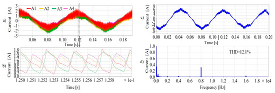
Figure 6 describes the experimental results of phase currents applying the proposed phase-shift CPWM. According to the analytical models in Section 3, the carrier phase angles , , and are applied to the four subsystems accordingly. Similar to Figure 5, Figure 6a shows the four subsystem phase current waveforms, while Figure 6b presents the cursor range of Figure 6a. According to Figure 6b, it is can be seen that the phase currents in the carrier signal period range are effectively shifted with proposed phase-shifted CPWM, while they are synchronized in Figure 5b. Figure 6c,d show the equivalent phase currents waveform and its FFT spectrum applying the proposed phase-shift CPWM.
The current THD of Figure 6a,c are 36.1% and 12.1%, respectively. In terms of Figure 5a and Figure 6a, it can be observed that the phase current THD is slightly increased with phase-shifted CPWM. This is mainly caused by the mutual coupling effect among machine stator windings, and the increase of phase current THD will result in a higher copper loss of the machine. Different machine stator layouts will result in different mutual coupling effect, which is worthwhile for further analysis in the future. However, this work is mainly aimed at the elimination of the equivalent phase currents to reduce the flux linkage harmonics, torque ripple, vibration and noise in the multi three-phase drives. Figure 6c shows that the equivalent current waveforms are significantly smoothed in respect with Figure 5c, and the current THD is reduced from 28.5% in Figure 5c to 12.1% in Figure 6c. Comparing Figure 5d,c, the majority of phase current harmonic components in Figure 6d are eliminated, except the harmonics around 8 kHz and 16 kHz, which are four times and eight times the switching frequency, respectively ( and ). This result matches the analytical Equations (16) and (17) in Section 3 and the FFT spectra in Figure 3 (the layer of ). Therefore, the experimental results have validated that the total equivalent phase currents can be effectively mitigated with the phase-shifted CPWM.
5. Conclusions
This work proposed a phase-shifted CPWM approach to eliminate the equivalent phase current harmonics in quadruple three-phase drives. The optimal carrier phase shift angles are proposed referring to the mathematical equivalent phase current models introduced in Section 3. There is more dominant phase current harmonics elimination with the increasing number of subsystems. The quadruple multi three-phase drive system with the proposed carrier phase angles of , , and is verified with experimental tests. The experimental results shows that, applying the proposed CPWM, the equivalent phase current harmonics components are effectively eliminated at the multiples of switching frequency, except the harmonic components around four times and eight times of the switching frequency. The equivalent phase current THD is reduced from 28.5% to 12.1% with the proposed phase-shifted CPWM. The main advantages of the proposed phase-shifted CPWM are listed as follows:
- (1)
- The phase-shifted CPWM can be applied into arbitrary multi three-phase drives.
- (2)
- The implementation of the proposed method is simple by changing the initial phase angles of carrier signals in the software.
- (3)
- Compared with previous research works targeted at torque ripple reduction, this work aims to reduce the total equivalent phase current harmonics, which makes the analytical models much easier. Additionally, the elimination of total equivalent phase current harmonics will result in significant machine performance improvement in terms of torque, vibration and noise.
Author Contributions
Conceptualization, X.W. and C.G.; validation, X.W. and H.Y. resources, H.Z.; writing—original draft preparation, X.W.; writing—review and editing, G.B.; supervision, G.B.; All authors have read and agreed to the published version of the manuscript.
Funding
This research was funded in part by the Natural Science Foundation of Zhejiang Province under Grant LQ19E070002 and in part by the Ningbo Science and Technology Beauro under Grant 2018B10002 and 2018B10001
Conflicts of Interest
The authors declare no conflict of interest.
Nomenclature
| Converter dc-link voltage | |
| Modulation index. | |
| , | Frequencies of the modulating and the carrier signals respectively. |
| , | Initial phase angles of the modulating and the carrier signals respectively. |
| , y | Time-varying angle of the carrier and the modulating signals respectively |
| Bessel function | |
| Switching frequency | |
| The hth harmonic impedance |
References
- Levi, E.; Bojoi, R.; Profumo, F.; Toliyat, H.A.; Williamson, S. Multiphase induction motor drives – a technology status review. IET Electr. Power Appl. 2007, 1, 485–516. [Google Scholar] [CrossRef]
- Baneira, F.; Yepes, A.G.; Lopez, O.; Doval-Gandoy, J. Estimation Method of Stator Winding Temperature for Dual Three-Phase Machines Based on DC-Signal Injection. IEEE Trans. Power Electron. 2016, 31, 5141–5148. [Google Scholar] [CrossRef]
- Abdel-Khalik, A.S.; Masoud, M.I.; Williams, B.W. Improved flux pattern with third harmonic injection for multiphase induction machines. IEEE Trans. Power Electron. 2012, 27, 1563–1578. [Google Scholar] [CrossRef]
- Valente, G.; Formentini, A.; Papini, L.; Gerada, C.; Zanchetta, P. Performance Improvement of Bearingless Multisector PMSM With Optimal Robust Position Control. IEEE Trans. Power Electron. 2019, 34, 3575–3585. [Google Scholar] [CrossRef]
- Dai, J.; Nam, S.W.; Pande, M.; Esmaeili, G. Medium-voltage current-source converter drives for marine propulsion system using a dual-winding synchronous machine. IEEE Trans. Ind. Appl. 2014, 50, 3971–3976. [Google Scholar] [CrossRef]
- Bennett, J.W.; Atkinson, G.J.; Mecrow, B.C.; Atkinson, D.J. Fault-tolerant design considerations and control strategies for aerospace drives. IEEE Trans. Ind. Electron. 2012, 59, 2049–2058. [Google Scholar] [CrossRef]
- Barrero, F.; Duran, M.J. Recent Advances in the Design, Modeling, and Control of Multiphase Machines—Part II. IEEE Trans. Ind. Electron. 2016, 63, 459–468. [Google Scholar] [CrossRef]
- Lopez, O.; Alvarez, J.; Doval-Gandoy, J.; Freijedo, F.D. Multilevel Multiphase Space Vector PWM Algorithm With Switching State Redundancy. IEEE Trans. Ind. Electron. 2009, 56, 792–804. [Google Scholar] [CrossRef]
- Levi, E.; Satiawan, I.N.W.; Bodo, N.; Jones, M. A space-vector modulation scheme for multilevel open-end winding five-phase drives. IEEE Trans. Energy Convers. 2012, 27, 1–10. [Google Scholar] [CrossRef]
- Carrasco, G.; Silva, C.A. Space vector PWM method for five-phase two-level VSI with minimum harmonic injection in the overmodulation region. IEEE Trans. Ind. Electron. 2013, 60, 2042–2053. [Google Scholar] [CrossRef]
- Ahmed, S.M.; Abu-Rub, H.; Salam, Z. Common-mode voltage elimination in a three-to-five-phase dual matrix converter feeding a five-phase open-end drive using space-vector modulation technique. IEEE Trans. Ind. Electron. 2015, 62, 6051–6063. [Google Scholar] [CrossRef]
- Bodo, N.; Levi, E.; Jones, M. Investigation of carrier-based PWM techniques for a five-phase open-end winding drive topology. IEEE Trans. Ind. Electron. 2013, 60, 2054–2065. [Google Scholar] [CrossRef]
- Yazdani, D.; Ali Khajehoddin, S.; Bakhshai, A.; Joós, G. Full Utilization of the Inverter in Split-Phase Drives by Means of a Dual Three-Phase Space Vector Classification Algorithm. IEEE Trans. Ind. Electron. 2009, 56, 120–129. [Google Scholar] [CrossRef]
- Ren, Y.; Zhu, Z.Q. Enhancement of steady-state performance in direct-torque-controlled dual three-phase permanent-magnet synchronous machine drives with modified switching table. IEEE Trans. Ind. Electron. 2015, 62, 3338–3350. [Google Scholar] [CrossRef]
- Patel, V.I.; Wang, J.; Wang, W.; Chen, X. Six-phase fractional-slot-per-pole-per-phase permanent-magnet machines with low space harmonics for electric vehicle application. IEEE Trans. Ind. Appl. 2014, 50, 2554–2563. [Google Scholar] [CrossRef]
- Sala, G.; Girardini, P.; Mengoni, M.; Zarri, L.; Tani, A.; Serra, G. Comparison of fault tolerant control techniques for quadruple three-phase induction machines under open-circuit fault. In Proceedings of the 2017 IEEE 11th International Symposium on Diagnostics for Electrical Machines, Power Electronics and Drives (SDEMPED), Tinos, Greece, 29 August–1 September 2017; pp. 213–219. [Google Scholar] [CrossRef]
- Calzo, G.L.; Zanchetta, P.; Gerada, C.; Gaeta, A.; Crescimbini, F. Converter topologies comparison for more electric aircrafts high speed Starter/Generator application. In Proceedings of the 2015 IEEE Energy Conversion Congress and Exposition (ECCE), Montreal, QC, Canada, 20–24 September 2015; pp. 3659–3666. [Google Scholar] [CrossRef]
- Calzo, G.L.; Zanchetta, P.; Gerada, C.; Lidozzi, A.; Degano, M.; Crescimbini, F.; Solero, L. Performance evaluation of converter topologies for high speed Starter/Generator in aircraft applications. In Proceedings of the IECON 2014 40th Annual Conference of the IEEE Industrial Electronics Society, Dallas, TX, USA, 29 October–1 November 2014; pp. 1707–1712. [Google Scholar] [CrossRef]
- Holmes, D.G.; Lipo, T.A. Pulse Width Modulation for Power Converters: Principles and Practice; Wiley: Hoboken, NJ, USA, 2003; ISBN 9780470546284. [Google Scholar]
- Levi, E.; Dujic, D.; Jones, M.; Grandi, G. Analytical Determination of DC-Bus Utilization Limits in Multiphase VSI Supplied AC Drives. IEEE Trans. Energy Convers. 2008, 23, 433–443. [Google Scholar] [CrossRef]
- Ryu, H.-M.; Kim, J.-H.; Sul, S.-K. Analysis of multiphase space vector pulse-width modulation based on multiple d-q spaces concept. IEEE Trans. Power Electron. 2005, 20, 1364–1371. [Google Scholar] [CrossRef]
- Hammond, P.W. A new approach to enhance power quality for medium voltage AC drives. IEEE Trans. Ind. Appl. 1997, 33, 202–208. [Google Scholar] [CrossRef]
- Fan, B.; Wang, K.; Zheng, Z.; Xu, L.; Li, Y. A new modulation method for a five-level hybrid-clamped inverter with reduced flying capacitor size. In Proceedings of the 2017 IEEE Energy Conversion Congress and Exposition (ECCE), Cincinnati, OH, USA, 1–5 October 2017; pp. 5262–5266. [Google Scholar] [CrossRef]
- Wang, X.; Sala, G.; Zhang, H.; Gu, C.; Buticchi, G.; Formentini, A.; Gerada, C.; Wheeler, P. Torque Ripple Reduction in Sectored Multi Three-Phase Machines Based on PWM Carrier Phase Shift. IEEE Trans. Ind. Electron. 2020, 67, 4315–4325. [Google Scholar] [CrossRef]
- Wang, X.; Yan, H.; Sala, G.; Buticchi, G.; Gu, C.; Zhao, W.; Xu, L.; Zhang, H. Selective Torque Harmonic Elimination for Dual Three-phase PMSMs Based on PWM Carrier Phase Shift. IEEE Trans. Power Electron. 2020, 1. [Google Scholar] [CrossRef]
- Valente, G.; Papini, L.; Formentini, A.; Gerada, C. Radial Force Control of Multi-Sector Permanent Magnet Machines for Vibration Suppression. IEEE Trans. Ind. Electron. 2018, 65, 5395–5405. [Google Scholar] [CrossRef]
- Pan, Z.; Bkayrat, R.A. Modular motor/converter system topology with redundancy for high-speed, high-power motor applications. IEEE Trans. Power Electron. 2010, 25, 408–416. [Google Scholar] [CrossRef]
- Liu, Z.; Zheng, Z.; Sudhoff, S.D.; Gu, C.; Li, Y. Reduction of Common-Mode Voltage in Multiphase Two-Level Inverters Using SPWM with Phase-Shifted Carriers. IEEE Trans. Power Electron. 2016, 31, 6631–6645. [Google Scholar] [CrossRef]
© 2020 by the authors. Licensee MDPI, Basel, Switzerland. This article is an open access article distributed under the terms and conditions of the Creative Commons Attribution (CC BY) license (http://creativecommons.org/licenses/by/4.0/).