Abstract
Recently, the construction of external ventilated walls has become popular for public and office buildings. These blocks are used without internal rendering because of their good interior surface, stable dimensions and various filling of masonry joints, which provide an attractive architectural appearance. However, problems with the airtightness of such walls often occur. Currently, there are no standard methods to predict the airtightness of such wall. In practice, samples of particular walls are produced, and their air permeability is measured at laboratories. For the broader use of the results of laboratory air permeability measurements, a methodology has been developed to predict the air permeability of block masonry walls using experimentally determined air flow resistances of the individual layers. The masonry from various blocks were used for the research; mineral wool boards of various air permeability were used for thermal insulation and the wind protection layer. After measuring the air resistance of the samples, the air flow resistances of walls of different construction were calculated. This study compared the calculated and measured air permeability values of different wall masonry samples and evaluated the suitability of created calculation method for prediction of the airtightness of insulated block masonry wall.
1. Introduction
The construction of external walls of various blocks, which are externally insulated with a mineral wool thermal insulation layer, with ventilated air gap and external finishing (ventilated wall structures), is the new solution for the fast and modern construction of public, office and residential buildings. Because of the good interior surface, stable dimensions and various filling of masonry joints, these blocks, used without internal rendering, can provide an attractive architectural appearance. Nevertheless, air penetrates through blocks without a rendering layer, their joints and insulation which makes the wall more air permeable. There is currently no information for designers and builders about the impact of non-rendered masonry on the overall airtightness of buildings. Even though this method reduces the costs and duration of construction work, it may increase overall building airtightness, which can cause high amounts of heat loss and uncontrolled air movement between, inside and outside of the building.
Building energy performance calculations are accurate only when building airtightness is measured [1,2]. These measurements help to evaluate the quality of the building execution and determine the airtightness level of the building, which is used for the calculation of the energy consumption of the building for the purposes of directive 2010/31/EU [3]. The most common building airtightness measurement method is the blower door test, according to EN ISO 9972:2015 [4,5]. The blower door technique determines the airtightness of a whole building by measuring the changing air volume in the internal volume of the building. During this test, there are possibilities for determining leaks or air penetration paths using non-destructive infrared thermography by observing the movement of cold air in the structure [6], using anemometer sensors by measuring the air movement velocity near the crack and calculating the approximate area of the crack [7], or even the hot box method, when leaks are detected by comparing the measurement and calculating the results of thermal transmittance and by additional IR (Infrared) analysis [8]. However, it is not possible to measure the air permeability value of certain elements, such as walls and windows, etc. The blower door technique has been adapted for the supply and exhaust of large amounts of air, so it is not suitable for determining the air permeability of wall samples, where small amounts of air could be used due to the small sample area.
The final building air permeability measurements are recorded after the building’s construction phase has been completed. Repair works could result in a high amount of money and time if any leakages are found after this phase. Therefore, it is important to know the structural solutions which are airtight and which solutions cannot guarantee the minimal requirement of building airtightness. The prediction of the air permeability of the building could help to ease the work of designers and builders and save time and money, by reducing the time wasted fixing mistakes made during the construction phase.
When measuring the airtightness of a building, air penetration paths are not analyzed; however, in the building design stage these paths and sealing materials are identified to ensure overall building airtightness. This means that overall building airtightness can be achieved when every separate part of the building is airtight. This includes walls, roof or ceilings, floors, windows, doors and the junctions between them.
Building airtightness can be predicted in several ways [9]: by theoretical [10,11], empirical [12,13,14,15,16], building characteristic or single component models [17]. Theoretical models recognize a building as an aggregation of numerous cracks. Each crack can be modeled individually using Computational Fluid Dynamics (CFD). Nevertheless, these models are not suitable for practical use [10] because of the calculation time [11] and power necessary to obtain accurate and effective models.
Empirical models are used when huge quantities of blower door data are collected. There are two types of empirical model: the regression analysis and the artificial neural network. The regression analysis is a statistical tool used to create mathematical relations between airtightness and various parameters [18]. This model is accurate only when similar buildings with similar properties are used for the analysis. Mostly, regression analysis is used for describing and analyzing the specific building stock. Another type of empirical model is the artificial neural network, which has the capabilities of learning and adaptation from few processing units to many connections which leads to the modification of units in order to adapt them if new data are received [19]. H. Krstic et al. (2014) validated a neural network model using in situ measurements data from Croatia [20] and Serbia [21]. After that, they improved their method by adding airtightness measurement results of similar construction type buildings from Poland [22]. In all their papers, it was proven that this kind of prediction model has the potential to predict airtightness for new buildings. Although the problems with this prediction model are that there are many different types of building construction and an insufficiency of airtightness measurement results. Calculations are only suitable for similar locations, climatic zones and types of building construction.
The building characteristic model is based on calculating airtightness by multiplying coefficients describing the type of construction, type of roof, the workmanship, building envelope area, facade and the building shape [23]. A designer can calculate the airtightness of the building using coefficients of parts of building envelope by a bonus/penalty increase based on certain parameters. This method was created in 1998 and is now outdated. It is not suitable for buildings with new building technologies and airtightness requirements [24,25].
Single component models deal with the air permeability of building parts separately instead of for the whole building. The air leakages of all the components constituting a building can be summed and the whole building’s air leakage can be determined [17]. A similar type of airtightness calculation is suggested in the construction technical regulation for Lithuania [26]. In this calculation, the air permeability of every window and door from the air permeability test protocols by EN12114 [27] are used for the predictive calculation of the airtightness of building. The air permeability of other parts of the building envelope are evaluated using a coefficient which was generated from the building blower door testing database. There are no standards or regulations for the air permeability testing of separate parts of building envelope, except for windows, doors and gates.
As mentioned by M. Prignon et al. (2017) in their literature review [23], the single component model is the most promising, although a large database should be created from air permeability laboratory testing results for different types of construction. In this database, one of most important components would be to categorize constructions by type and uniform metrics, so that usage of this calculation tool would be as practical as possible.
Air leakage paths can occur through the construction unit or through joints between construction elements. For example, when investigating air permeability through the element chimneys of lightweight aggregate concrete, the authors of [28] found that installing a chimney to the wall or in the corner reduces airtightness. Surface treatment also influences air permeability.
In their study, T. O. Relander et al. (2011) investigated the airtightness of the joints between the basement wall and the wood-frame wall [29]. Their results showed higher airtightness for constructions where malleable sealing materials were used. These sealing materials were practically not affected by the flatness or load of the constructions that they were used with.
There is also other research about the airtightness of different construction solutions. J. Hallik et al. (2019) investigated air leakage through various timber joints filled with three different polyurethane foams [30]. Their results showed that the biggest influence on air permeability were the surface properties and width of the joint. There were no significant changes in results by changing the type of the foam.
T. Kalamees et al. (2017) measured air leakage levels for eight joints which were used for different tightening solutions in the prefabricated timber-framed building envelope [31]. It was discovered that there was a large difference between the measurements in laboratories and in situ. Workmanship quality created air leakage places (plumbing penetrations, electrical service penetrations, etc.), and was identified as main reason behind this difference. As other similar research mentions, a larger database with different joints and different material and workmanship combinations is required for further investigations.
When measuring in situ, the air permeability results of some parts of the building envelope may differ from laboratory measurements. An example presented in the study of M. Pinto et al. (2011): in situ measured window air permeability was 200% higher than the value presented by the window assembly manufacturer [32], although it was clear that window was installed without following the technical instructions prepared by the window manufacturer.
J. Langmans et al. (2016) investigated the impact of climatic conditions on the airtightness of typical taped joints [33]. In this case, an air barrier was realized at the exterior. The results showed that temperature, rain and frost cycles had an impact on the air permeability of a taped air barrier, but the increase was still very small.
P. F. Pereira et al. (2014) compared the results of airtightness measurements of building construction junctions in situ and in the laboratory. Air penetration through three different paths was measured before and after sealing: the window frame, the connection of the steel columns with floors and the roof ridge. The roof ridge had the most influence on building airtightness, while window frame joints had the least influence. The laboratory and in situ air permeability values of construction junctions did not align. This might be because of the problems related to construction defects and the varying quality of workmanship [34].
Research into the air permeability of different construction types helps to find out the ways that air moves through different parts of a building envelope. In this paper, air leakage through various segments of masonry walls with insulation of different rock wool boards were measured. One of the main purposes of this research is to investigate the possibility of calculating the air permeability of the completed wall segment by knowing air resistance of every element constituting the wall. This could help to create a more versatile airtightness prediction tool based on laboratory measurements data.
2. Strategy, Materials and Methods
2.1. Main Steps for the Investigation Strategy for the Prediction of Airtightness of Thermally Insulated Walls Structures with Block Masonry
As mentioned in introduction, the most accurate method for predicting the airtightness of any structure is to measure their samples in laboratories. That is quite simple for any lightweight, homogeneous constructions (insulation boards, prefabricated panels); but it is complicated to measure masonry wall in laboratory conditions because of its weight, dimensions and the labor required for the specimen preparation and installation. A simplified strategy was created for this study to obtain more summarized data from laboratory measurements of various wall samples with block masonry (Figure 1). The stages of the study were:
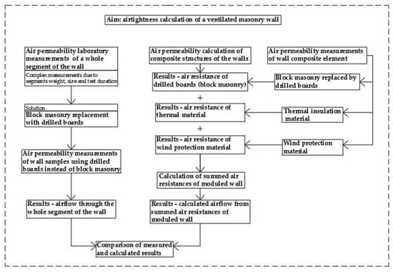
Figure 1.
Layout of sequential arrangement of performed research.
- The validation test of drilled wood fiber cement boards used instead of block masonry in insulated wall samples for air permeability measurements;
- The creation of a calculation method for the prediction of the airtightness of wall samples using laboratory air permeability measurements data of wall components;
- Laboratory measurements of the air permeability of modeled wall samples and separate materials constituting these samples;
- The comparison of the calculated and measured air permeability values of modeled wall samples and the evaluation of the suitability of the created calculation method for the prediction of the airtightness of thermally insulated block masonry wall;
- Practical recommendations for the design and execution of block masonry walls without internal rendering to meet the high requirements of building airtightness.
2.2. Theoretical Provisions of the Method for the Prediction of the Airtightness of a Composite Structure by Calculation Using Laboratory Air Permeability Measurements Data of Constituting Components
No references were found in the scientific publications concerning methodologies for calculating the air permeability of a composite structure using the measured air resistances of the constituting layers. The literature on the fundamentals of civil engineering presents the essential provisions for the calculation of air movement through the partitions of buildings by analogy with heat transfer. K. F. Fokin [35], without considering the paths through which air penetrates through the building structure due to the difference of air pressure ∆P, presented a formula for the calculation of air flow W moving through the composite partition:
where ∑RH is the sum of the air resistances of the partition layers.
H. Hens [36] classified the partitions of buildings according to the nature of their air permeability. There are structures made of porous materials through which air can penetrate evenly; structures of airtight elements with air-permeable interconnections; and structures with holes, cracks and other leaks, often due to unintentional circumstances (damage, a poor joint filler or loose connection). For air movement in an open porous material, the present authors applied Poiseuille’s law of proportionality between air flow rate and driving force, the case being the change of air pressure per unit length. The proportionality factor is called air permeability ka, units m3/m·h·Pa:
The minus sign in the equation indicates air flows from points at a higher to points at a lower air pressure. Permeability increases with the open porosity and the number of macro pores in a material.
To calculate the air flow Ga through the layers of the structure, depending on the type of air penetration through them, the author provided the following formula:
where Ka, KaΨ and Kaχ are the air permeances and ΔPa the air pressure differentials. These air permeances were determined experimentally for each specific layer.
The air movement through the layers of homogeneous porous materials is simple to predict. The air flow through such a layer is inversely proportional to the specific air resistance of the layer. To calculate the specific air resistance Rsc, the ratio between thickness (d, m) and air conductivity (ka, m3m·h·Pa) of the material is as follows:
Air conductivity ka is a property of porous material, so it is possible to calculate the air resistance of any thickness of the layer material and use it to calculate the amount of penetrating air.
For non-homogeneous materials with undefined holes and leaks, the air resistance Rsm was calculated according to the formula:
where Ql is the measured air permeability of layer m3/h·m2.
Using the measured air resistances of the separate layers, the air permeability of a composite structure can be calculated by the following formula:
More complex predictions of air permeability are required in the case of structure layers with joints, cavities and leaks. Because there are difficult to calculate, measure their dimensions and generally predict their occurrence in real building structures, an evaluation of the average air permeability analogous to the porous material was applied. However, there was an essential difference: the air permeability through such layers depends on the thickness, so their specific air resistances could not be calculated. The air resistance of each thickness of material constituting layer was determined by experimental measurements.
After evaluating the analyzed theoretical knowledge of air movement through the layers of building materials, a simplified methodology for predicting air permeability through the construction of insulated masonry was developed:
- The air resistance of block masonry Rm was calculated for each thickness of a particular masonry using air permeability measurement results;
- The air resistance of the thermal insulation layer Rt was calculated from the declared or measured air permeability ka and the thickness of the material;
- The air resistance of the wind protection layer Rw was calculated from the declared or measured air conductivity ka and the thickness of the material. The air resistance of wind protection boards with coatings was measured for a specific product thickness and coating type.
The air flow through the composite structure was calculated according to the formula:
2.3. Equipment and Methods for Laboratory Measurements
The measurements of air permeability of block masonry wall samples, thermal insulation, wind protection boards and modeled insulated structures were made using a KS 3030/650PC device (Figure 2).
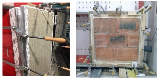
Figure 2.
Specimens installed into the air permeability measuring device: drilled wood fiber cement board + insulation in wooden frame (left), and a specimen of ceramic block masonry filled with horizontal joints (right).
The pressure measuring ranges of the calibrated device were ±4000 Pa with uncertainty of measurement 0.2%. The airflow measurement ranged from 0.2–500 m3/h with uncertainty of measurement 0.75%. The device has metrological calibration and the calculation of measurement uncertainties was confirmed by a national accreditation body.
The prepared specimens were installed in the opening of the test chamber and sealed. Measurements were done by supplying air into test chamber and creating pressure difference between, inside and outside of the specimen. The airflow through the specimen was measured and recorded. The pressure difference during the measurement was changed from 10 Pa to 100 Pa, as it is specified in the blower door test standard EN ISO 9972:2015 for the airtightness measurement of buildings.
2.4. Materials, Products and Modeled Wall Samples Used for Investigations
Four types of blocks were chosen for this research: aerated concrete and ceramic blocks that had high result in airtightness, and two types of expanded clay blocks that are not airtight but have different air permeability. Blocks with masonry installed without vertical joints have a special shape to connect the blocks in a row without masonry mortar, maintaining the direction of masonry, ensuring mechanical stability, and reducing the heat transfer coefficient of masonry. The shape of the block connection is such that the air permeability is as low as possible, but it is not evaluated by tests or calculations; this can only be done by measuring the air permeability of the block masonry. Seven block masonry wall samples were made from these blocks using different masonry technology with different joint fillings (Figure 2). Aerated concrete, ceramic and lower airtightness expanded clay block masonry wall samples were in two types: filled H-only horizontal joints and filled H+V- horizontal and vertical joints. The wall samples of higher airtightness expanded clay blocks only had horizontal joint filling and their surface was plastered. The types of blocks and their joint filling technology for the construction of masonry are shown in Table 1.

Table 1.
Types of blocks and their joint filling technology.
Due to the heaviness and thickness of the specimens and the complicated installation of completed insulated wall samples into the test device, it was decided to replace the block masonry with perforated wood fiber cement board (thickness of 8 mm) with drilled holes of a 5 mm diameter to simulate air movement through block masonry. The number of holes was calculated considering the results of the air permeability measurements of block masonry wall samples. Numbers were assigned to panels with different numbers of holes: panel no. 1–5, panel no. 2–20, panel no. 3–50 and panel no. 4–70 holes.
Rock wool boards with air permeability of 49 × 10−6 m3/m·s·Pa were used for the thermal insulation layer of masonry wall. The thermal insulation layer was created from one or two rock wool boards, each of 10 cm thickness. The wind protection layer was made from a 2 cm thickness rock wool board (air permeability 9.4 × 10⁻⁶ m3/m·s·pa) or a 5 cm thickness rock wool board (air permeability 30.6 × 10⁻⁶ m3/m·s·Pa).
The following wall structures were modeled for every block masonry simulation panel, with different numbers of drilled holes:
- Panel + rock wool 10 cm;
- Panel + rock wool 2 × 10 cm;
- Panel + rock wool 10 cm + rock wool wind protection 5 cm;
- Panel + rock wool 10 cm + rock wool wind protection 2 cm;
- Panel + rock wool 2 × 10 cm + rock wool wind protection 2 cm.
The modeled wall samples were installed into wooden frames, sealed, and then fixed in the air permeability measurement device (Figure 2).
3. Results
3.1. Validation Test of Drilled Wood Fiber Cement Boards Use Instead of Block Masonry in Insulated Wall Samples for Air Permeability Measurements
The laboratory measurement results of the air permeability of various block masonry wall samples and wood fiber cement boards with drilled holes are shown in Figure 3. The presented graphical results show that the dependence of the air movement through the block masonry and through the perforated boards on the pressure difference was very close to the linear one; therefore the air flow through these structures could be evaluated as laminar. All types of masonry can be divided into four groups by results of the measured air permeability. Wall samples made of aerated concrete, ceramic block masonry with filled horizontal and vertical joints, and wall samples made of silicate block masonry with only filled horizontal joints had the lowest air permeability. The masonry with lower air permeability was the expanded clay with filled horizontal joints and a plastered surface and can be added to this group of specimens. All these samples were replaced with panel no. 1 with 5 drilled holes, the area of which was 1.36 cm2/m2. Higher air permeability was fixed when the masonry of expanded clay with filled horizontal and vertical joints were measured. This kind of block masonry is exceptional because during the test air moved through many small pores in the block, where the dependency of air permeability on pressure difference was not linear. This kind of block masonry was replaced with panel no. 2 with 20 drilled holes, which had a 5.45 cm2/m2 panel area. The air permeability measurement results of panel no. 2 matched the appropriate results of block masonry when the pressure difference was lower. The ceramic block masonry wall samples with filled horizontal joints were assigned to the third group. The precision of ceramic block dimensions were significantly lower than that of aerated concrete blocks; therefore, additional cracks in vertical filling appeared that made the masonry leakier. Panel no. 3 with 50 drilled holes, with a 13.63 cm2/m2 of panel area was chosen to replace this group of blocks. The expanded clay block masonry without vertical joint filling was the leakiest sample. The air leaked through the blocks and through vertical joints. Panel no. 4 with 70 drilled holes, with a 19.08 cm2/m2 panel area was chosen to replace of this kind of block masonry. As it can be seen from Figure 3, the air permeability of this panel was close to the permeability of the block masonry over the whole range of pressure differences.
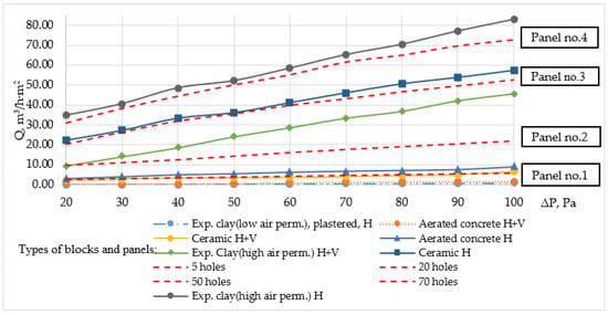
Figure 3.
Air permeability measurement results of various block masonry wall samples and drilled wood fiber cement boards.
3.2. Laboratory Measurements of the Air Permeability of Thermal Insulation and Wind Protection Rock Wool Boards Used in Research
The measurement results of the air permeability of mineral wool thermal insulation and wind protection boards are presented in Figure 4. The graphical presentation of the dependences of air permeability on the pressure difference also show the laminar air movement through these materials over the whole range of pressure differences.
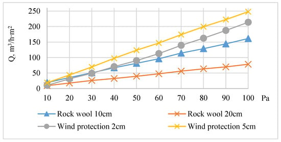
Figure 4.
The measured air permeability of different types of rock wool thermal insulation and wind protection boards.
The results of the air permeability measurements of single- and double-layer thermal insulation rock wool confirm the theoretical assumption that the air permeability of homogeneous porous materials was directly proportional to their thickness over the entire range of pressure differences. The air permeability values of the rock wool calculated from the results of this measurement corresponded to the values declared by their manufacturers within ±5%.
3.3. Calculation of Air Permeability of Composite Wall Samples Using Air Permeability Measurement Data of Wall Constituting Layers
Using the measured air permeability of perforated wood fiber cement boards, which simulate different block masonry samples, and rock wool thermal insulation and wind protection boards, air resistance was calculated for every component of the insulated wall samples at air pressure difference of 50 Pa, according to Equation (5). The air resistance of the perforated boards and rock wool products are presented in Table 2.

Table 2.
The specific air resistance of the materials used in study.
After the determination of the air resistance of every component of the wall sample, the air resistances of the modeled walls were calculated by summing the air flow resistances of the wall constituting layers. The calculated air resistance of the various wall samples at a pressure difference of 50 Pa are shown in Figure 5. The calculations of air resistance clearly showed that the air resistance of the whole structure was predetermined by the air resistance of the perforated board simulating the masonry. Thermal insulation and wind protection layers increase the resistance of the whole structure to air permeability: in absolute value, similar to all modeled structures; in percentage value the influence of these layers is greatest for the masonry with the least air permeability, i.e., the perforated boards.
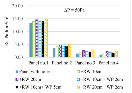
Figure 5.
Air flow resistances of four different panels with added thermal insulation and wind protection boards. RW = rock wool thermal insulation, WP = wind protection.
Using the calculated air resistance of the wall samples, the air permeability of this structure at a 50 Pa air pressure difference was calculated using Equation (7). The results showed that the installation of thermal insulation and wind protection layers in the walls significantly reduced the air permeability of the whole wall only when the air permeability of the masonry layer was low. In order to check the reliability of the calculation results, measurements of air permeability of simulated structures were performed in a laboratory testing device.
3.4. Laboratory Measurements of Air Permeability of Modeled Wall Samples
The wall samples containing perforated panels and different rock wool boards were mounted into wooden frames. Air permeability was measured by changing the pressure difference from 20 Pa to 100 Pa. The measurement was performed at first by applying the positive pressure to the rock wool boards, and later to the drilled boards. The first case of the measurement corresponding air permeability dependence was drawn on a pressure difference graph for each assembly.
For a more convenient comparison of results, the air permeability dependence on the air pressure difference of wall samples with the same perforated panel is presented in one figure.
As it can be seen from the results, rock wool thermal insulation boards made very little impact on the air permeability of the modeled wall structure in all intervals of applied pressure difference. A greater impact on air permeability was noticed when wind protection boards made from rock wool were used. The thickened thermal insulation when wind protection boards are added reduces the air permeability of the whole construction. The comparison of the measured and calculated air permeability of different wall samples and their matching tendencies are presented in Figure 6.
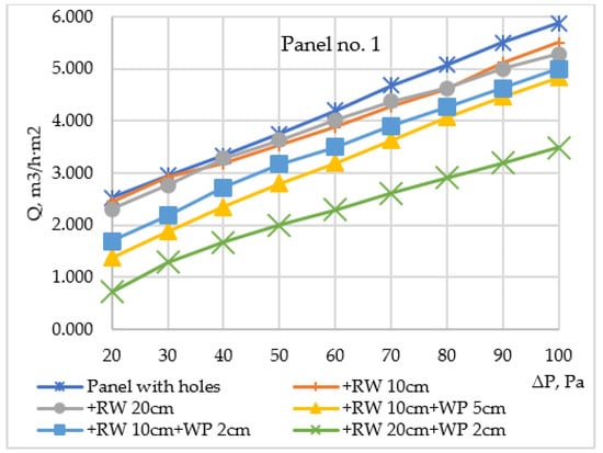
Figure 6.
Panel no. 1: air permeability dependence on pressure difference when various insulation variants were applied.
The air permeability measurement results of construction with panel no. 2 are shown in Figure 7.
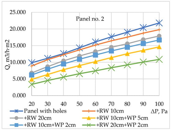
Figure 7.
Panel no. 2: air permeability dependence on pressure difference when various insulation variants were applied.
All the results show greater air permeability since panel no. 2 was less airtight than panel no. 1. As can be seen from Figure 6, the thicker rock wool thermal insulation layer used without wind protection boards had a greater impact on the reduction of air permeability. A thicker rock wool thermal insulation layer and a lower air permeability of wind protection layer shows the lowest air permeability results for the whole structure.
The air permeability measurement results of wall sample with panel no. 3 are show in Figure 8. In this case, the thermal insulation layer was becoming more significant as the air permeability of panel no. 3 was less airtight than the two used before. The air permeability of the whole construction decreased almost twice only by doubling the construction thermal insulation layer from 10 cm to 20 cm. Even though the wind protection layer impact was less significant, its installation can reduce the air permeability of the whole construction by almost 3 times.
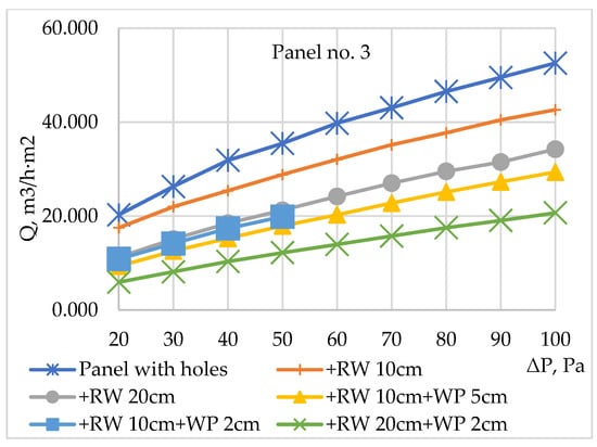
Figure 8.
Panel no. 3: air permeability dependence on pressure difference when various insulation variants were applied.
The air permeability measurement results of construction with panel no. 4 are show in Figure 9.
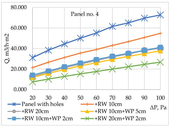
Figure 9.
Panel no. 4: air permeability dependence on pressure difference when various insulation variants were applied.
In this case, when the panel no. 4 with the highest air permeability was installed, higher air permeability of the whole structure was gained, and the impact of the thermal insulation and wind protection layers on the construction’s air permeability was even more significant, although it is obvious that priority must be given to air barriers when seeking airtightness of the insulated wall. Thermal and wind protection layers can decrease the air permeability of the wall segment, but they will never make it airtight.
In the second case, when the higher pressure is at the perforated plate side, the measured air permeability values are given in Table 3.

Table 3.
Calculated and measured values of construction air permeability at 50 Pa pressure difference.
3.5. Comparison of the Calculated and Measured Air Permeability of the Construction
After the air permeability of modeled wall samples were measured and calculated, the air permeability of wall samples at 50 Pa air pressure difference were compared. The results are shown in Table 3.
The smallest differences between the calculated and measured air permeability for both cases of pressure application were found for the samples when all perforated panels were only insulated with 20 cm thickness rock wool panels. The measured air permeability of samples with panel no. 1 was higher by 5–6%, and with the other panels by 10–12%. This shows that, with a higher thickness of the air-permeable material, the air easily finds a path through the holes in the plate; this does not significantly change the type of air movement through the materials.
When perforated panels are insulated with a thin layer of 10 cm thick rock wool thermal insulation, higher air permeability was obtained when higher pressure was on the side of the panel. The higher-pressure air passing through the holes of the perforated panel presses on the rock wool fibers, making it easier to find paths for further movement. In the case of panel no. 1, where there was a positive pressure on the perforated panel side, about 20% more air passed through the sample than the figure that calculated. The pressure of the air passing through the drilled holes was highest, so when air enters the fibrous structure it thins it, making a suitable path to move on. At the highest pressure on the rock wool side, the results of the calculation and measurement of the air permeability of the sample were very close because air cannot change the structure of the rock wool.
The measured air permeability of the samples with 10 cm thermal insulation and 5 cm thick wind protection rock wool boards was lower than the calculated one in almost all cases (except for panel no. 4, which was very air permeable). This difference was smaller when the pressure on the plate side was higher. By adding higher pressure on the wind protection side, the air enters inside of the thermal insulation board at a slightly lower pressure, thus losing a lot of energy to find the further path, resulting in less air passing through the sample. When the pressure on the panel side is higher, the air passing through the holes easily finds a further path of movement, making the measured air permeability closer to the calculated one. Similar trends were observed in samples with 10 cm thermal insulation and 2 cm wind protection, only in these cases the differences between calculated and measured air permeability were much smaller: denser and less-air-permeable wind protection reduces the air pressure and the air loses less energy finding a path through the holes in the perforated panel.
The largest differences between the calculated and measured air permeability were obtained for samples with 20 cm thick thermal insulation and 2 cm thick wind protection rock wool boards. The largest differences were in the case of a low-air-permeable perforated panel. Here, the difference decreased with the increasing air permeability of the panel, especially in the case of the addition of higher pressure on the perforated plate side. A thicker layer of air-permeable thermal insulation material is a space for free air movement not only in the direction of pressure drop, but also in all other directions. As a result, air entering this layer changes the nature of its movement toward turbulence and loses energy for further motion.
4. Discussion
The analysis of the results of the measurement and calculation of the air permeability of wall structures showed that the prediction of the air permeability of composite structures according to the air resistance summed up of the air resistances of composite layers, applying analogy with heat transfer, gave quite different errors. The reasons for the discrepancies have been discussed in the results section, but there is not enough research data in this area to explain, substantiate and evaluate them in more detail by improving the method of the air permeability calculation of composite structures. As already mentioned in the introduction, no examples of analogous research have been found in scientific publications; therefore, it is not possible to compare the results of the research with those of other researchers and to determine in more detail the reliability and especially the versatility of the air permeability prediction method. However, the essence of the method of predicting the air permeability of a composite partition is presented in the basic literature of civil engineering (indicated in the introduction); therefore, the method has the background to be the subject of experimental research and analysis, especially now, when the relevance of building airtightness assessment, and, consequently, prediction in the early stages has increased significantly. The application of the fundamental laws of physics (energy conservation, ideal gas) for the development of methods for predicting the air permeability of building structures is not recommended even by scientists from these fields, because the non-uniformity and uncertainty of the structure of building materials would give large errors. The results of this study could be considered as one of the first steps to developing a method for predicting the air permeability of composite building structures. The development of these investigations would contribute to a more intensive use of the single component model to predict the airtightness of the entire building, as some of the component air permeability measurements could be replaced by calculations.
5. Conclusions and Recommendations
The conducted research was an initial attempt at the development of a wall air permeability prediction tool according to building component air permeability model.
The results of experimental measurements and calculations revealed:
- An analysis of the feasibility of replacing block masonry with perforated board in experimental research has shown sufficient coinciding of the air permeability test results. This amendment is proposed to be used in further investigation for less complex installations of insulated wall samples into measurement device.
- An analysis of the air permeability calculation and measurement results of wall samples showed smaller differences in cases where the nature of air movement (laminar to turbulent) through a single material remained similar to the nature of air movement through the same material incorporated in the structure. This is typical of walls with a lower thickness of thermal insulation and of more air-permeable wind barrier.
- The different air permeability calculation and measurement results were obtained in cases where the air movement parameters through a single material and through the same material incorporated in the structure have changed. This is typical of walls with very different air permeability properties of components, especially at high thicknesses of air-permeable thermal insulation products.
- Studies have shown that the nature of air movement through a single layer may differ from that of air movement through the same product contained in a composite structure. The purpose of further research will be to find out the causes and circumstances of such changes.
- The ventilated facades of buildings made of masonry blocks without internal plastering meet the requirements of building airtightness only if the blocks themselves are airtight, and the vertical and horizontal joints are carefully filled with masonry mortar. Additionally, the use of lower-air-permeability thermal insulation materials is recommended to prevent the increase in air permeability in the event of unforeseen cracks and leaks in the masonry.
Author Contributions
Conceptualization, V.P.; resources, K.B.; writing—original draft preparation, V.G.; writing—review and editing, R.B.; visualization, J.K.; supervision, R.B. All authors have read and agreed to the published version of the manuscript.
Funding
This research received no external funding.
Conflicts of Interest
The authors declare no conflict of interest.
References
- Šadauskienė, J.; Seduikyte, L.; Paukštys, V.; Banionis, K.; Gailius, A. The role of air tightness in assessment of building energy performance: Case study of Lithuania. Energy Sustain. Dev. 2016, 32, 31–39. [Google Scholar] [CrossRef]
- Cardoso, V.E.M.; Pereira, P.F.; Ramos, N.M.M.; Almeida, R. The Impacts of Air Leakage Paths and Airtightness Levels on Air Change Rates. Buildings 2020, 10, 55. [Google Scholar] [CrossRef]
- European Union. Directive 2010/31 EU of the European Parliament and the Council of 19 May 2010 on the energy performance of buildings. Off. J. Eur. Commun. 2010, L153, 21–22. [Google Scholar]
- International Organization for Standardization (ISO). EN ISO 9972:2015—Thermal Performance of Buildings–Determination of Air Permeability of Buildings–Fan Pressurization Method; International Organization for Standardization: Geneva, Switzerland, 2015. [Google Scholar]
- Muñoz, J.F.; Poza-Casado, I.; Gonzalez-Lezcano, R.-A.; Pardal, C.; Echarri-Iribarren, V.; De Larriva, R.A.; Fernández-Agüera, J.; Dios-Viéitez, M.J.; Del Campo-Díaz, V.J.; Calderín, M.M.; et al. Methodology for the Study of the Envelope Airtightness of Residential Buildings in Spain: A Case Study. Energies 2018, 11, 704. [Google Scholar] [CrossRef]
- Lucchi, E. Non-invasive method for investigating energy and environmental performances in existing buildings. In Proceedings of the 27th Conference on Passive and Low Energy Architecture, Louvain-la-Neuve, Belgium, 13–15 July 2011; pp. 571–576. [Google Scholar]
- Lucchi, E.; Pereira, L.D.; Andreotti, M.; Malaguti, R.; Cennamo, D.; Calzolari, M.; Frighi, V. Development of a Compatible, Low Cost and High Accurate Conservation Remote Sensing Technology for the Hygrothermal Assessment of Historic Walls. Electronics 2019, 8, 643. [Google Scholar] [CrossRef]
- Lucchi, E.; Roberti, F.; Alexandra, T. Definition of an experimental procedure with the hot box method for the thermal performance evaluation of inhomogeneous walls. Energy Build. 2018, 179, 99–111. [Google Scholar] [CrossRef]
- Relander, T.-O.; Holøs, S.B.; Thue, J.V. Airtightness estimation—A state of the art review and an en route upper limit evaluation principle to increase the chances that wood-frame houses with a vapour- and wind-barrier comply with the airtightness requirements. Energy Build. 2012, 54, 444–452. [Google Scholar] [CrossRef]
- Younes, C.; Shdid, C.A. A methodology for 3-D multiphysics CFD simulation of air leakage in building envelopes. Energy Build. 2013, 65, 146–158. [Google Scholar] [CrossRef]
- Wang, L.; Chen, Q. Validation of a Coupled Multizone-CFD Program for Building Airflow and Contaminant Transport Simulations. HvacR Res. 2007, 13, 267–281. [Google Scholar] [CrossRef]
- Chan, W.R.; Joh, J.; Sherman, M.H. Analysis of air leakage measurements of US houses. Energy Build. 2013, 66, 616–625. [Google Scholar] [CrossRef]
- Montoya, M.I.; Pastor, E.; Carrié, F.R.; Guyot, G.; Planas, E. Air leakage in Catalan dwellings: Developing an airtightness model and leakage airflow predictions. Build. Environ. 2010, 45, 1458–1469. [Google Scholar] [CrossRef]
- Pan, W. Relationships between air-tightness and its influencing factors of post-2006 new-build dwellings in the UK. Build. Environ. 2010, 45, 2387–2399. [Google Scholar] [CrossRef]
- Fernández-Agüera, J.; Domínguez-Amarillo, S.; Sendra, J.J.; Suarez, R. An approach to modelling envelope airtightness in multi-family social housing in Mediterranean Europe based on the situation in Spain. Energy Build. 2016, 128, 236–253. [Google Scholar] [CrossRef]
- Bramiana, C.; Entrop, A.; Halman, J. Relationships between Building Characteristics and Airtightness of Dutch Dwellings. Energy Procedia 2016, 96, 580–591. [Google Scholar] [CrossRef][Green Version]
- Hassan, O.A. An alternative method for evaluating the air tightness of building components. Build. Environ. 2013, 67, 82–86. [Google Scholar] [CrossRef]
- Sykes, A.O. An introduction to regression analysis. In Coase-Sandor Institute for Law & Economics Working Paper; University of Chicago Law School: Chicago, IL, USA, 1993. [Google Scholar]
- Krose, B.; van der Smagt, P. An introduction to Neural Network; The University of Amsterdam: Amsterdam, The Netherlands, 1996. [Google Scholar]
- Krstić, H.; Koški, Ž.; Otković, I.I.; Španić, M. Application of neural networks in predicting airtightness of residential units. Energy Build. 2014, 84, 160–168. [Google Scholar] [CrossRef]
- Krstić, H.; Otković, I.I.; Todorović, G. Validation of a Model for Predicting Airtightness of Residential Units. Energy Procedia 2015, 78, 1525–1530. [Google Scholar] [CrossRef]
- Krstić, H.; Otković, I.I.; Kosiński, P.; Wojcik, R. Validation of neural network model for predicting airtightness of residential and non-residential units in Poland. Energy Build. 2016, 133, 423–432. [Google Scholar] [CrossRef]
- Prignon, M.; Van Moeseke, G. Factors influencing airtightness and airtightness predictive models: A literature review. Energy Build. 2017, 146, 87–97. [Google Scholar] [CrossRef]
- Gids, W.D.; Cornelissen, H.; Jong, P. Infiltratieverliezen U Bouw; TNO Bouw en Ondergrond: Delft, The Netherlands, 2010. [Google Scholar]
- Orme, M.; Liddament, M.W.; Wilson, A. Numerical Data for Air Infiltration & Natural Ventilation Calculations; AIVC: Coventry, UK, 1998; p. 44. [Google Scholar]
- STR 2.01.02:2016 Pastatų Energinio Naudingumo Projektavimas ir Sertifikavimas. Available online: https://e-seimas.lrs.lt/portal/legalAct/lt/TAD/15767120a80711e68987e8320e9a5185/asr (accessed on 21 May 2020).
- Technical Committee ISO/TC 163, EN 12114. Thermal Performance of Buildings-Air Permeability of Building Components and Building Elements-Laboratory Test Method; BSI: Brussels, Belgium, 2015. [Google Scholar]
- Relander, T.-O.; Kvande, T.; Thue, J.V. The influence of lightweight aggregate concrete element chimneys on the airtightness of wood-frame houses. Energy Build. 2010, 42, 684–694. [Google Scholar] [CrossRef]
- Relander, T.-O.; Heiskel, B.; Tyssedal, J.S. The influence of the joint between the basement wall and the wood-frame wall on the airtightness of wood-frame houses. Energy Build. 2011, 43, 1304–1314. [Google Scholar] [CrossRef]
- Hallik, J.; Gustavson, H.; Kalamees, T. Air Leakage of Joints Filled with Polyurethane Foam. Buildings 2019, 9, 172. [Google Scholar] [CrossRef]
- Kalamees, T.; Alev, Ü.; Pärnalaas, M. Air leakage levels in timber frame building envelope joints. Build. Environ. 2017, 116, 121–129. [Google Scholar] [CrossRef]
- Pinto, M.; Viegas, J.; De Freitas, V. Air permeability measurements of dwellings and building components in Portugal. Build. Environ. 2011, 46, 2480–2489. [Google Scholar] [CrossRef]
- Langmans, J.; Desta, T.Z.; Alderweireldt, L.; Roels, S. Durability of self-adhesive tapes for exterior air barrier applications: A laboratory investigation. Int. J. Vent. 2016, 16, 30–41. [Google Scholar] [CrossRef]
- Pereira, P.F.; Almeida, R.M.S.F.; Ramos, N.M.M.; Sousa, R. Ventilation and Airtightness in Transforming the Building Stock to High Performance. In Proceedings of the 35th AIVC Conference, Poznan, Poland, 24–25 September 2014; pp. 24–25. [Google Scholar]
- Fokin, K.F. Стрoительная Теплoтехника Ограждающих Частей Зданий; АВОК-ПРЕСС: Moscow, Russia, 2006. [Google Scholar]
- Hens, S.L.C.H. Building Physics-Heat, Air and Moisture 3e Fundamentals and Engineering Methods with Examples and Exercises; John Wiley & Sons: Hoboken, NJ, USA, 2017; pp. 135–141. [Google Scholar]
© 2020 by the authors. Licensee MDPI, Basel, Switzerland. This article is an open access article distributed under the terms and conditions of the Creative Commons Attribution (CC BY) license (http://creativecommons.org/licenses/by/4.0/).