Article

Active Disturbance Rejection Control of Differential Drive Assist Steering for Electric Vehicles

1
State Key Laboratory of Automotive Simulation and Control, Jilin University, Changchun 130022, China
2
Motor Technical Center, Shanghai Automotive Industry Corporation, Shanghai 201804, China
3
Department of Mechanical and Aerospace Engineering, University of California Davis, Davis, CA 95616, USA
*
Author to whom correspondence should be addressed.
Energies 2020, 13(10), 2647; https://doi.org/10.3390/en13102647
Submission received: 4 May 2020 / Revised: 19 May 2020 / Accepted: 20 May 2020 / Published: 22 May 2020

Abstract

:
The differential drive assist steering (DDAS) system makes full use of the advantages of independent control of wheel torque of electric vehicle driven by front in-wheel motors to achieve steering assistance and reduce the steering effort of the driver, as the electric power steering (EPS) system does. However, as an indirect steering assist technology that applies steering system assistance via differential drive, its linear control algorithm, like existing proportion integration differentiation (PID) controllers, cannot take the nonlinear characteristics of the tires’ dynamics into account which results in poor performance in road feeling and tracking accuracy. This paper introduces an active disturbance rejection control (ADRC) method into the control issue of the DDAS. First, the third-order ADRC controller of the DDAS is designed, and the simulated annealing algorithm is used to optimize the parameters of ADRC controller offline considering that the parameters of ADRC controller are too many and the parameter tuning is complex. Finally, the 11-DOF model of the electric vehicle driven by in-wheel motors is built, and the standard working conditions are selected for simulation and experimental verification. The results show that the ADRC controller designed in this paper can not only obviously reduce the steering wheel effort of the driver like PID controller, but also have better nonlinear control performance in tracking accuracy and smooth road feeling of the driver than the traditional PID controller.

1. Introduction

With the intensification of interest in environmental protection and energy issues, electric vehicles have ushered in significant development opportunities. Compared with traditional centralized drive electric vehicles, the torque of each wheel of an electric vehicle driven by several in-wheel motors, also commonly called independent-wheel-drive electric vehicle (IWDEV), can be independently controlled. Differential drive assist steering (DDAS) is a novel power steering technology based on the unique advantages of independent-drive of the electric vehicle driven by several in-wheel motors [1]. It uses the different driving force of two-side front wheels to generate steering assistance, which can substitute the traditional power steering system, such as hydraulic power steering (HPS) system or electric power steering (EPS) system. The reason is that the DDAS technology has the advantages of more compact structure and lower cost. Specifically, on the one hand, the DDAS system does not need an add-on actuator, like the steering motor of the EPS system. On the other hand, due to having the same actuators, the in-wheel motors, with the driving system the controller of the DDAS system can be integrated into the vehicle driving controller. Hence, the DDAS technology appeals to many researchers’ attention and interest.
Although the concept of DDAS has only been proposed in recent years, many scholars have conducted much research and achieved some progress. Wang [1] first proposed the concept of DDAS technology, conducted a theoretical analysis and proposed a steering-wheel-torque direct control strategy based on an anti-windup PID algorithm. The steering assist feasibility, steering return ability and driving torque coordination of the DDAS were studied in depth and verified by software simulations and real vehicle tests. Zhao [2] further studied a coupling control strategy of force and displacement for a DDAS system to improve the steering maneuverability and handling stability of EVs with motorized wheels. By analyzing the key factors that affect the interaction between vehicle and driver, the optimum hand wheel torque of a DDAS system is designed and achieved by the torque difference between two front wheels based on H2/ H∞ control method, and its effectiveness was verified by a MatLab/Simulink software (MathWorks, Natick, Massachusetts, USA) simulation. Hu [3] studied the lane keeping control for four-wheel independently actuated autonomous vehicles only when the active-steering motor entirely fails and designed an adaptive multivariable super-twisting control strategy and verified its effectiveness by CarSim (Mechanical Simulation Corporation, Ann Arbor, Michigan, USA) and Simulink co-simulations. Kuslits [4] proposed a full state feedback control system for scenarios at higher speeds, whereas a simple angle tracking controller can be used for a DDAS system in scenarios at lower speed. The effectiveness of the strategy was verified through simulations. Peng [5] developed a coordinated steering control strategy with a hierarchical structure for a multi-axle independent-drive electric vehicle, which is steered simultaneously by traditional mechanical steering and differential drive steering and verified the effectiveness of the strategy through simulations. Wang [6] also designed a hierarchical coordinated controller for the DDAS and vehicle stability control based on the phase plane theory. Various typical simulations on roads with different adhesion characteristics showed the effects on expanding the working range of DDAS systems and simultaneously mitigating the additional influence of the DDAS on vehicle stability. Römer [7] studied the potential of independent-wheel-drive influencing the driver’s steering torque using a control technique based on classical EPS control plans, and compared the energy saving potential of DDAS system with the conventional EPS system. The energy saving potential was proved through realistic driving cycles experiments which included the Karlsruhe motorway, the Herzogenaurach highway and a trip through the city of Karlsruhe. It was concluded that the DDAS system can save up to 121.93 Wh/100 km of energy, or approximately 0.95% in lateral acceleration ranges below 4.5 m/ s 2 , and about 0.43% (55.2 Wh/100 km) in mean value compared to a conventional EPS system. Interestingly, if the tractive energy of an independent-wheel-drive electric vehicle is considered, the comprehensive energy conservation generated by the optimization of the two-side differential drive torque, as DDAS does, can reach up to 4% without any loss of vehicle stability [8].
A review of these references shows that a DDAS system can be used to substitute for a traditional power steering system, such as EPS and as a result, the energy consumption of these traditional add-on assistance steering systems is removed. Although the aspect of energy conservation is not the core purpose of our research, it can be concluded that the existing studies of DDAS system have proved the apparent engineering application value of this novel technology and its feasibility for providing steering assistance and the coordination issue with other chassis control system have been well studied in the above existing literature. However, other important aspects, such as the steering assistance quality issue of DDAS system, are also important factors determining whether this technology can be finally applied in practice. Unfortunately, the steering assistance quality of the DDAS system, which reflects smooth steering hand force with less interference and good tracking performance with ideal steering force characteristic, has not been widely studied until now. To better understand this requirement of the technology, the basic principles and assistance characteristics of a DDAS system and some previous experimental results have to be reviewed and discussed first. Figure 1 shows the working principle diagram of a DDAS system.
As shown in Figure 1, the DDAS system maintains the traditional mechanical steering mechanism but removes the power assist steering actuators, such as a hydraulic cylinder or an electric motor. Since the longitudinal driving force of the left and right steering wheels of the IWDEV is independent and controllable, the torque generated by the front wheels around the respective kingpin can be unequal. Here we define this torque as the driving steering torque. At the same time, because the two steering wheels are connected by the steering trapezium and have a fixed geometric motion relationship, therefore, the driving steering torque will drive the two steering wheels to turn to the side with a small driving force. In theory, the controller of the DDAS system controls the outer steering wheel to increase the driving torque properly and the inner steering wheel to reduce the driving torque equally, which can ensure that the driving steering torque generated by the inner steering wheel and the outer steering wheel on the steering rack are exactly equal to the required steering power torque. It is obvious that the DDAS system can realize the power steering function without changing the total driving torque. Compared with a traditional EPS system, the DDAS system can achieve the same power steering effect without needing a power assist steering actuator. The DDAS system saves the part of energy used to drive the power assist steering actuator, so the DDAS system must be more energy-saving compared with a traditional EPS system. Since the energy consumption of the power assist steering actuator is small, the energy saving of the DDAS system is limited, but it still plays an important role in improving the driving range of pure electric vehicles. DDAS system has the same actuator, two front in-wheel motors, as the driving system of IWDEV, and the DDAS electric control unit (ECU) is also integrated into the driving controller. Consequently, a DDAS system has advantages over other power assist steering systems in layout and cost.
However, it should be noted that the DDAS system is an indirect power steering system, that is, the steering assistance provided by the system is achieved by indirectly acting on the mechanical steering rack through changing the tire forces of two-side steerable driving wheels. The steering assistance generated by DDAS system can be expressed as follows:
F a s t = ( T 1 T 3 ) r σ r w N L + I w ( d ω 1 d t d ω 3 d t ) r σ r w N L
where T1 and T3 are the driving torques of the left and right front wheels, r σ is the scrub radius, r w the tire rolling radius, N L is the transmission ratio of the rack translation to the knuckle arm angular displacement, I w is the moment of inertia of the wheel about its central axis, ω 1 and ω 3 are the rotational velocity of left and right front wheels. According to Equation (1), it can be seen that the assistance provided by the DDAS system is related to the wheel rotational dynamic characteristics and suspension parameters. During the operation of the vehicle, tires may work in a nonlinear range, and the scrub radius of the wheels is also constantly changing. In addition, the steering wheel torque/angle sensor noise may also have a great impact on the control of a DDAS system.
Based on the review of the characteristics of DDAS technology, its control issue has also been studied in many published references. Most of the researchers applied conventional control algorithms, such as classical open-loop look-up table control plan [7] like EPS does, anti-windup PID control plan [6] and fuzzy adaptive PID control plan [1] to the control issue of DDAS system and the their control effects on steering assistance and returnability performance look good in the corresponding simulations, but the control effects of these classic linear control methods on the steering assistance qualities, such as road feeling, the steering wheel torque control stability and robustness against system parameters variation and sensor noise in real applications, are considered to be unacceptable. To better understand the lack of competence of the traditional linear PID control plan with fixed control parameters, Figure 2 shows a real world double-lane-change road test result of the steering wheel torque of an IWDEV that is controlled by a conventional anti-windup PID controller based on a DDAS system published in reference [1]. It can be seen that the PID controller has poor tracking performance to the reference steering wheel torque though the steering assistance function is achieved. This means the smooth road feeling and accurate hand force feedback cannot be fully achieved in the real application of PID controllers for DDAS system. In addition, because the nonlinear mathematical models of tire dynamics, steering system and suspension system are difficult to establish accurately, the changing laws of these interferences are difficult to identify. Thus, despite having better robustness and optimality, some advanced controllers that depend on the accurate model of the controlled system with interference observer or estimator, such as H infinite control, linear quadratic regulator (LQR) control, etc. may be not easy or suitable to apply to the DDAS system, too.
In summary, though the driver’s steering effort can be obviously reduced by the DDAS system, it can be seen from the above analysis that the selected control strategies and control algorithms may highly impact its effect on steering assistance quality. This performance will ultimately decide whether this novel power assistance steering technology can be actually applied in a real car. In this paper, having good robustness in nonlinear control issues, the use of the active disturbance rejection control (ADRC) method is attempted for this purpose. As an improved form of PID controller, the ADRC approach combines the advantages of the PID controller and some robust algorithms. It is relatively easy to implement, robust against possible system interferences and one does not need to know an accurate controlled system model [9].
Compared with the existing literature, the main purpose or main contribution of this paper is that we try to pay more attention on the improvement of the steering assistance quality of the DDAS system before its real application, and firstly attempt to apply the ADRC control approach to improve the steering assistance quality of the DDAS system, in order to make the driver have a better road feeling, and achieve a smooth steering force with less interference caused by possible sensor noise and model parameter changes.
The structure of this paper is as follows: Firstly, the independent-wheel-drive electric vehicle model with four degrees of freedom mechanical steering system is established, and then the ADRC controller model of DDAS is designed for the steering-wheel-torque direct control strategy. Secondly, aiming at solving the problem that the parameters of the ADRC controller are numerous and difficult to set, a simulated annealing algorithm is used to optimize the parameters offline. Finally, typical driving conditions are selected for simulation and experimental verification, which verify the effectiveness of the control method proposed in this paper.

2. Independent-Wheel-Drive Electric Vehicle Dynamic Model

Figure 3 shows the overall framework of the independent-wheel-drive electric vehicle model, which is composed of a vehicle body model, mechanical steering system model, DDAS controller model, wheel rotation dynamics model, tire model and in-wheel-motor model, etc. The specific modelling processes of the core parts are shown in the following subsections, the DDAS controller model is introduced in Section 3, and for the others readers may refer to [1,10]. The descriptions of all the symbols of the variables can be found in the nomenclature section.

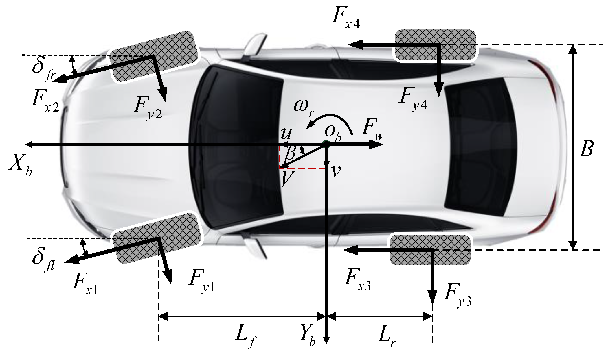
2.1. Vehicle Body Dynamic Model

The vehicle body dynamic model established in this paper includes three degrees of freedom: longitudinal motion, lateral motion and yaw motion [1,10]. As shown in Figure 4, the following equations can be established:
m ( u ˙ v ω r ) = F x 1 cos δ f l + F x 2 cos δ f r + F x 3 + F x 4 F y 1 sin δ f l F y 2 sin δ f r 1 2 C D ρ A u 2
m ( v ˙ + u ω r ) = F y 1 cos δ f l + F y 2 cos δ f r + F y 3 + F y 4 + F x 1 sin δ f l + F x 2 sin δ f r
I z ω ˙ r = ( F x 2 cos δ f r F y 2 sin δ f r F x 1 cos δ f l + F y 1 sin δ f l ) B 2   + ( F x 4 F x 3 ) B 2    + ( F x 2 sin δ f r + F y 2 cos δ f r + F x 1 sin δ f l + F y 1 cos δ f l ) L f ( F y 4 + F y 3 ) L r
where F x i and F y i ( i = 1 , 2 , 3 , 4 ) are the longitudinal and lateral forces of the left front wheel, the right front wheel, the left rear wheel, and the right rear wheel respectively; m is the mass of the whole vehicle, u and v are the longitudinal and lateral speed of the body centroid respectively, ω r is the yaw rate of the vehicle body, I z is the inertia of the body around the vertical axis, C D is the air resistance coefficient, ρ is the air density, A is the frontal area, δ f l and δ f r are the steering angles of the left front wheel and the right front wheel, L f is the distance from the body centroid to the front axle, L r is the distance from the body centroid to the rear axle, B is the wheelbase.

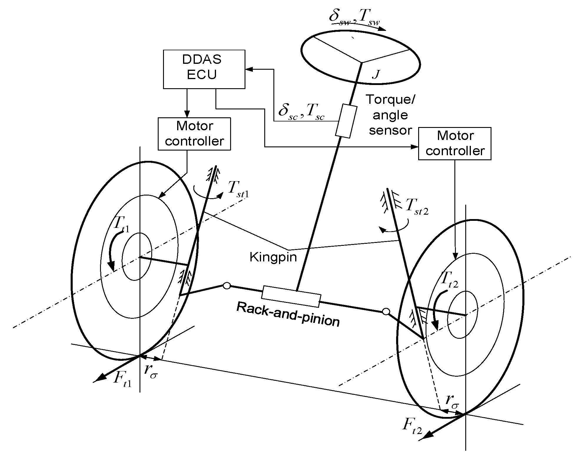
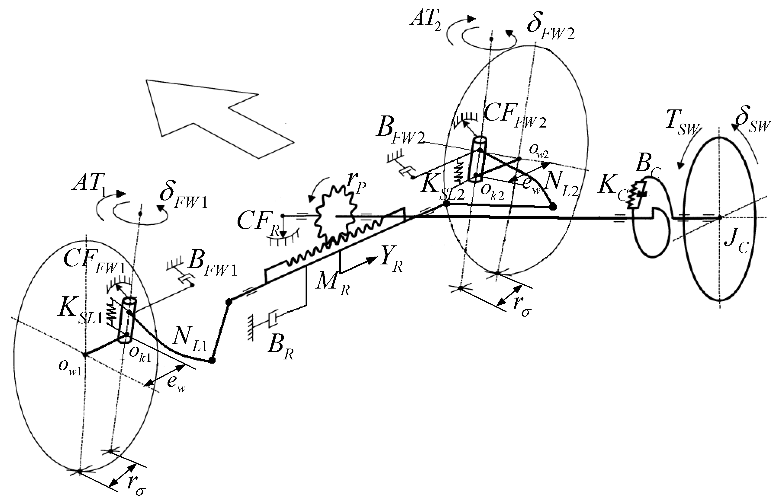
2.2. Four-DoF Mechanical Steering System Sub-Model

As mentioned above, the DDAS system maintains the mechanical steering system. The four degrees of freedom model of the steering system is shown in Figure 5. The corresponding dynamic equations of the steering system are shown as follows [11,12]:
J C δ ¨ s w + B C δ ˙ s w + K C ( δ s w Y R r P ) = T s w
M R Y ¨ R + B R Y ˙ R + η F K C r P ( Y R r P δ s w ) + C F R + η B ( T K L 1 N L 1 + T K L 2 N L 2 ) = 0
J F W 1 δ ¨ F W 1 + B F W 1 δ ˙ F W 1 + C F F W 1 + A T 1 = T K L 1
J F W 2 δ ¨ F W 2 + B F W 2 δ ˙ F W 2 + C F F W 2 + A T 2 = T K L 2
T K L 1 = K S L 1 ( Y R N L 1 δ F W 1 )
T K L 2 = K S L 2 ( Y R N L 2 δ F W 2 )
T S C = K C ( δ s w Y R r P )
where T s w is the steering wheel torque, B C and J C are the damping of the steering column and equivalent inertia of steering wheel and column, δ s w is the steering wheel angle, M R and B R are the mass and damping of the rack, Y R is the displacement of the rack, r p is the radius of the pinion, η f and η B are the forward transmitting efficiency and backward transmitting efficiency of the steering gear respectively, K C is the torsional stiffness of the torsion bar, C F R is the Coulomb friction of the gear and rack [13], N L i is the ratio of the rack transfer displacement to knuckle angular displacement, J F W i and B F W i ( i = 1 , 2 ) are the inertia of the road wheels round their kingpin and damping of kingpin, C F F W i is the coulomb friction caused by the left front wheel and the right front wheel rotating the kingpin, and the specific calculation formula is shown in the literature [14], T K L i is the total torque from the kingpins of the left front wheel and the right front wheel, δ F W i is the steering angle of front wheels, K S L i is the torsional stiffness of the kingpin of the front wheels.
A T i represents the alignment torque of each front wheel around the kingpin, which is mainly composed of the following four parts [15,16]:
M s y = F y · r w sin τ cos σ
M s x = F x · r σ cos τ cos σ
M z z = M t z · cos τ cos σ
M s z = F z · cos τ sin σ sin δ F W cos σ ( r σ + r w tan σ )
where M s y is the alignment torque generated by the lateral force of the tire, M s x is the alignment torque generated by the longitudinal force of the tire, M z z is the component of the self-alignment torque around the kingpin, M s z is the alignment torque generated by the normal force of the front axle, M t z is the self-alignment torque of the tire, F x is the longitudinal force of the wheels, F y is the lateral force of the wheels, F z is the normal force of the wheels, τ is the kingpin caster angle, σ is the kingpin inclination angle.

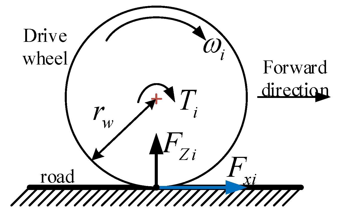
2.3. Wheel Rotation Dynamic Sub-Model

The wheel rotation dynamic model is shown in Figure 6.
The rotation dynamic equation of each driving wheel can be established as follows:
I w ω ˙ i = T i F x i r w
where I w is the moment of inertia of the wheels, ω i ( i = 1 , 2 , 3 , 4 ) is the angular velocity of the wheels, T i ( i = 1 , 2 , 3 , 4 ) is the driving torque of the wheels.

2.4. Tire Sub-Model

The tire model is an important part of the vehicle dynamic model. This paper selects the magic formula tire model which is widely used in the study of handling dynamics. The specific definition and parameters of the model are detailed in the literature [17].

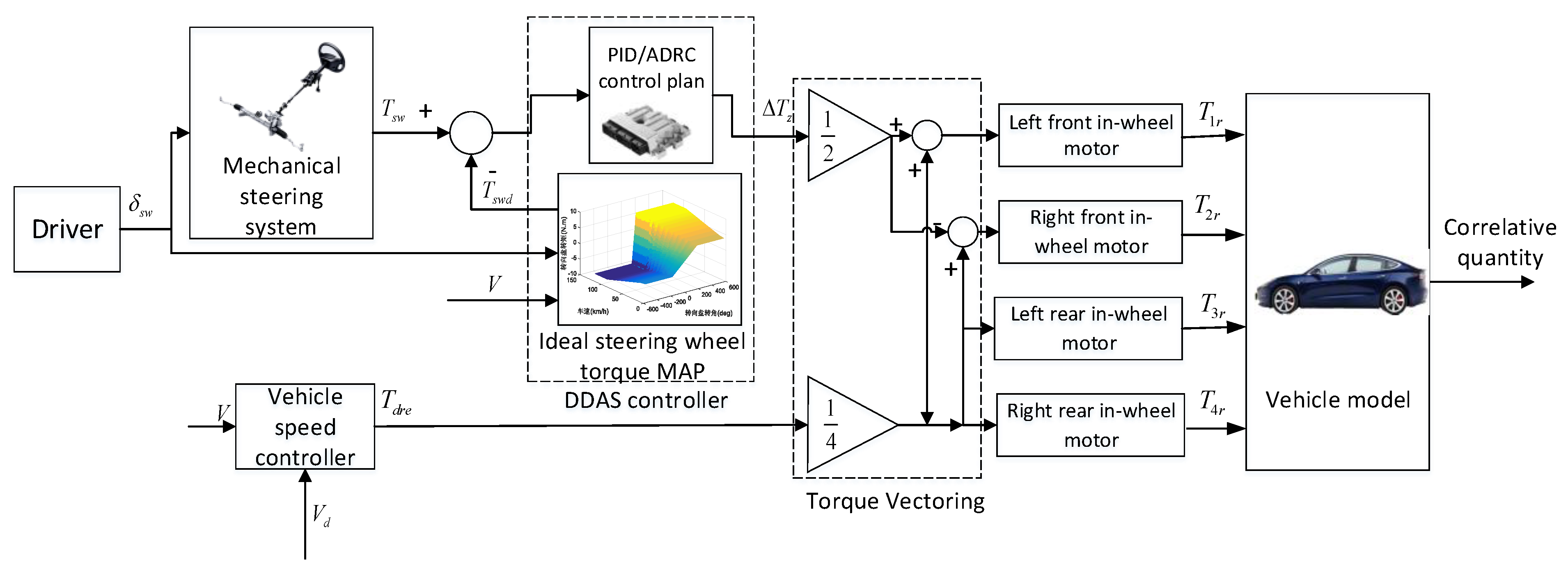
3. Design of DDAS Controller

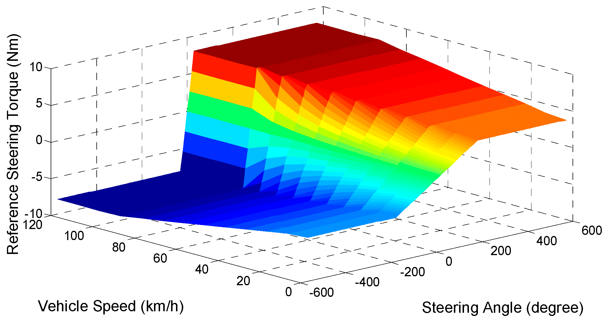
3.1. Steering-Wheel-Torque Direct Control Strategy

The existing DDAS controller mostly adopts an open-loop strategy based on an assist characteristic curve look-up table inherited from the EPS control plan [7,18]. Different from the working principle of an EPS system, the steering assistance generated by a DDAS system through the ground traction force difference is indirectly applied on the steering system. Given the complexity of real road conditions and nonlinear characteristics of vehicle tires as well as inconstant scrub radius, acquiring the actual ground traction force accurately is difficult. Hence, a traditional control strategy like EPS which generates the steering assistance torque command directly based on a look-up table of control current of the steering electric motor is hard to implement. In another words, it is difficult to directly determine the torque commands of the two front in-wheel motors, since we do not know the accurate law that defines how much torque difference can generate required steering assistance torque for the steering system. Therefore, a reference steering wheel torque following control law called as steering-wheel-torque direct control strategy has to be proposed to avoid the embarrassment that the steering assistance torque is hard to know in DDAS system. It is proved that this control strategy is suitable to solve this problem and it is not hard to be carried out in real applications. The architecture of the steering-wheel-torque direct control strategy is shown in Figure 7.
As Figure 7 shows, the actual steering wheel torque T s w is measured through a steering wheel torque sensor and the steering wheel angle δ s w is measured through a steering wheel angle sensor, and the vehicle speed signal V is obtained from the CAN bus. Then δ s w and V are delivered to the ideal steering wheel torque map to obtain the target steering wheel torque T s w d . The difference of the ideal steering wheel torque T s w d and the actual steering wheel torque T s w is delivered to the DDAS controller to obtain the front wheels torque difference Δ T z . The front wheels torque difference Δ T z is distributed by the torque vectoring block, as shown in the Equation (17), which distributes half of the torque difference to the two side wheels with equal absolute value but opposite sign. Then the differential of ground traction force of the front wheels generated by torque vectoring makes the actual steering wheel torque track the ideal steering wheel torque, which consequently reduces the steering wheel hand force of the driver:
{ T 1 , T 2 = T d r e 4 ± Δ T z 2 T 3 , T 4 = T d r e 4
where T d r e is the total demand driving torque determined by the longitudinal driver model, which can be calculated by the following formula:
T d r e = k p ( V d V ) + k i 0 t ( V d V ) d t + k d d ( V d V ) d t
where V d is the target speed, k p is the proportional coefficient of the PID controller, k i is the integral coefficient of the PID controller, k d is the differential coefficient of the PID controller.
As for the driver’s ideal steering wheel torque, many research institutes have conducted a lot of researches very early, mainly through real vehicle test or driving simulator measurement. According to the previous research conclusion, the preference steering wheel torque characteristic of many drivers is closely related to the vehicle speed and the steering wheel angle [19,20,21,22]. Hence, as an example, a kind of driver’s preference steering wheel torque map derived from other’s experimental results is illustrated in Figure 8.

3.2. Design of the ADRC Controller of DDAS System

As discussed in Section 1, on one hand, the control effect of a conventional controller may be influenced by several interferences, such as inevitable steering wheel torque sensor noise and frequently changing suspension parameters as well as continuous road unevenness, while on the other hand, the change laws of these interferences are hardy to identify and accurately model. Therefore, PID control plans, especially the ones with fixed control parameters, as well as some robust and optimization control plan may not be competent for the DDAS control problem. As a result, the ADRC control method which has good robustness against inner parameter changes and outer sensor noise without knowing the accurate mathematical model of the controlled system in advance is proposed for the DDAS control system. Actually, as an improved PID controller, the ADRC controller treats the inner and outer interferences as a whole interference and the influence of the interference on the control effect is compensated by the disturbance estimation compensator. Therefore, compared with a PID controller, the ADRC controller has better anti-interference ability.
The ADRC controller is mainly composed of four parts: tracking differentiator, extended state observer, nonlinear state error feedback law and disturbance estimation compensator [23]. ADRC controller solves the problem that the differential signal of the error is difficult to extract in the traditional PID controller by using the tracking differentiator and the extended state observer. The extended state observer of ADRC controller obtains the state of the system, the differential signal of the state and the disturbance acting on the system by observing the input and output of the system. The nonlinear state error feedback of ADRC makes the controller more adaptive to nonlinear system by introducing nonlinear function fal. The disturbance estimation compensator of the ADRC controller can compensate the control result of nonlinear state error feedback by choosing appropriate compensation coefficient, so as to effectively reduce the influence of disturbance on control effect.
According to the characteristics of the DDAS system, the specific structure of the third-order ADRC controller of DDAS system designed in this paper is shown in Figure 9.
The specific design process of the ADRC controller of DDAS system is introduced as follows:
(a) Tracking differentiator.
In classical control theory, the differential value of a given signal is solved by the following equation:
y = w ( s ) v = s T s + 1 v = 1 T ( 1 1 T s + 1 ) v
where T is the time constant of the controlled system. The smaller the time constant T is, the closer the output of the system is to the real differential value of the signal. Therefore, the time constant is usually a small value [9]. The structure which tracks the dynamic characteristics of the signal as fast as possible through the first order inertia link and obtains the approximate differential signal by solving the differential equation is called a tracking differentiator.
To track the dynamics of the input signal fast, generally, the following nonlinear tracking differentiator can be selected:
{ x ˙ 1 = x 2 x ˙ 2 = R sign ( x 1 v 0 + x 2 | x 2 | 2 R )
where v 0 is the ideal steering wheel torque T s w d , R is the speed factor. The tracking performance is better when the R is bigger, which means that x1 and x2 are closer to v 0 and the differential of v 0 , respectively.
Although the nonlinear tracking differentiator can track the target steering wheel torque T s w d well, it is easy to generate high frequency oscillation due to the bang-bang characteristic of the selected sign function in Equation (20). In order to prevent the occurrence of high frequency oscillations when the system comes into a steady state, this paper uses the time-optimal control synthesis function f h a n ( x 1 , x 2 , R , h ) to design the tracking differentiator. The specific formula of this function is as follows [24]:
{ d = R · h d 0 = h · d y = x 1 + h x 2 a 0 = d 2 + 8 r | y | a = { x 2 + 0.5 ( a 0 d ) sign ( y ) ,   | y | > d 0 x 2 + y h ,   | y | d 0 f h a n = { R sign ( a ) ,   | a | > d R a d ,   | a | d
where h is the tracking step and R is the speed factor.
Therefore, the final designed tracking differentiator in this paper is as follows:
{ x ˙ 1 = x 2 x ˙ 2 = f h a n ( x 1 T s w d , x 2 , R , h )
(b) Extended state observer.
In the running process of the system, signal interaction with the external environment is constantly carried out. Therefore, the internal state information of the system can be determined by monitoring the system input and output. The device for determining the internal state information of the system is called the state observer [9].
For a general nonlinear system as shown in the following equations:
{ x ˙ 1 = x 2 x ˙ 2 = f ( x 1 , x 2 ) + b u y = x 1
Then the state observer of this system can be established as follows by selecting a nonlinear feedback form:
{ e = z 1 y z ˙ 1 = z 2 γ 01 g 1 ( e ) z ˙ 2 = γ 02 g 2 ( e ) + b u
where γ 01 , γ 02 are control parameters, e is the error term, u is the external input, g i ( e ) is nonlinear function that satisfies the following conditions:
e g i ( e ) 0
As long as the appropriate γ 01 , γ 02 and nonlinear function g i ( e ) are chosen for the state observer, the state variables can be well estimated in a wide range of system. Let x 3 ( t ) = f ( x 1 ( t ) , x 2 ( t ) ) , and denote x ˙ 3 ( t ) = w t . Then, the system can be expanded into a new linear control system as follows:
{ x ˙ 1 = x 2 x ˙ 2 = f ( x 1 , x 2 ) + b u x ˙ 3 = w ( t ) y = x 1
The state observer established for this new expanded control system is as follows:
{ e = z 1 y z ˙ 1 = z 2 γ 01 g 1 ( e ) z ˙ 2 = z 3 γ 02 g 2 ( e ) z ˙ 3 = γ 03 g 3 ( e ) + b u
This new state observer is known as the extended state observer of the new system. Among them, x 3 ( t ) is called the expanded state. According to the research needs of this paper, the third-order extended state observer established in this paper is rewritten as follows:
{ e = z 1 T s w z ˙ 1 = z 2 γ 01 e z ˙ 2 = z 3 γ 02 | e | α 1 sign ( e ) + b Δ T z z ˙ 3 = γ 03 | e | α 2 sign ( e )
In order to prevent the phenomenon of high frequency flutter in the control process, the function | e | α sign ( e ) in the extended state observer is replaced by the power function with linear segment at the origin as follows:
f a l ( e , α , ϕ ) = { e ϕ α 1 | e | ϕ | e | α sign ( e ) | e | > ϕ
where ϕ is the length of the linear segment and is an important parameter. The final third-order extended state observer is as follows:
{ e = z 1 T s w z ˙ 1 = z 2 γ 01 e z ˙ 2 = z 3 γ 02 f a l ( e , α 1 , ϕ 1 ) + b 0 Δ T z z ˙ 3 = γ 03 f a l ( e , α 2 , ϕ 2 )
where α 1 , α 2 are the nonlinear factors in the f a l function, z 1 tracks the target value of the actual steering wheel torque T s w , z 2 tracks the target signal of the changing speed of steering wheel torque, and z 3 tracks the total disturbance term of the system.
(c) Nonlinear state error feedback.
The nonlinear state error feedback is an important part of the ADRC controller. This part can quickly adjust the deviation and make the system balance between response fastness and overshoot. Hence, the following nonlinear state error feedback is chosen:
{ e 1 = x 1 z 1 e 2 = x 2 z 2 u 0 = γ 1 f a l ( e 1 , α 3 , ϕ 3 ) + γ 2 f a l ( e 2 , α 4 , ϕ 4 )
where e 1 is the steering wheel torque error term, e 2 is the steering wheel torque change rate error term, γ 1 and γ 2 are nonlinear combination coefficients, u 0 is the control output of the nonlinear state error feedback.
After completing the design of above three parts, the final control value can be obtained based on the nonlinear state error feedback control value plus the compensation of the disturbance estimation value. This part is called disturbance estimation compensator mentioned above, which is expressed as follows:
Δ T z = u 0 z 3 / b 0
where Δ T z is the front wheels torque difference required by the final decision of the ADRC controller, b 0 is the compensation factor, which determines the strength of the compensation and is an important parameter of the ADRC controller, directly affecting the ADRC controller performance [25].

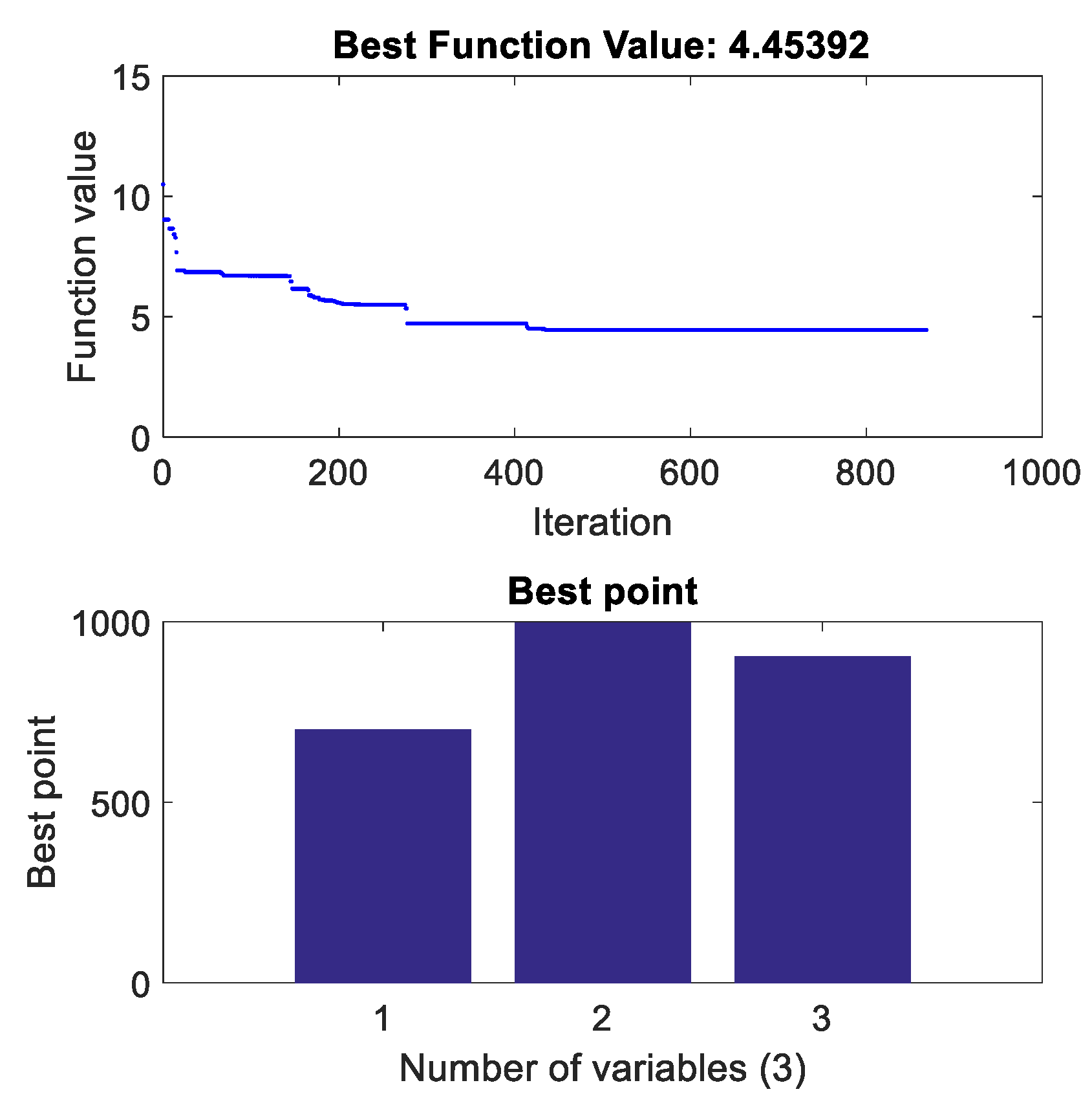
4. Controller Parameter Optimization Based on Simulated Annealing Algorithm

Compared with the PID controller, though the ADRC controller has the advantages of better robustness, simple structure and easy implementation without knowing the accurate mathematical model of the controlled system, it also has the disadvantages of needing more control parameters and complicated parameter tuning [26], which severely limits its further industrial application. At the same time, these parameters have a great impact on the performance of the controller, so appropriate method selection to set the values of each parameter has to be done first.
According to the theory of ADRC, some of the parameters are determined empirically, and once these parameters are determined, no correction is needed. For example, α 1 , α 2 , α 3 , α 4 and ϕ 1 , ϕ 2 , ϕ 3 , ϕ 4 are the parameters of the nonlinear function fal, which affect the change trend of the nonlinear function, but they usually do not change with the change of the controlled system. Therefore, the ranges of α 3 and α 4 in the nonlinear state error feedback are generally 0 < α 3 < 1 , α 4 > 1 , so in this paper, α 3 and α 4 are chosen as fixed values, 0.95 and 1.25, respectively, α 1 and α 2 in the third-order extended state observer are chosen as fixed values, 0.5 and 0.25, respectively. The values of ϕ 1 , ϕ 2 , ϕ 3 and ϕ 4 have a great influence on the nonlinearity of the controller. After multiple simulations, the value of ϕ 1 , ϕ 2 , ϕ 3 and ϕ 4 are chosen as 0.01 which is ten times of the sampling step. The value of speed factor R in this paper is 10.
In summary, in addition to the empirically determined parameters, the other parameters which need to be specifically set are the following six parameters γ 01 , γ 02 , γ 03 , γ 1 , γ 2 and b 0 . Generally, there is no relationship between the six parameters γ 01 , γ 02 , γ 03 , γ 1 , γ 2 , b 0 and the parameters α 1 , α 2 , α 3 , α 4 , ϕ 1 , ϕ 2 , ϕ 3 , ϕ 4 mentioned above. At the same time, γ 01 , γ 02 and γ 03 in the extended state observer are mainly related to sampling step size [23], which can be designed separately. In addition, γ 1 and γ 2 in nonlinear state error feedback are also important parameters of the controller and b 0 is an important parameter to characterize the difference of different systems. Due to the fact that there is a certain mutual influence between these parameters, and manual adjustment is too complicated, offline optimization to set the values of these six parameters is implemented. In this optimization process, three parameters γ 01 , γ 02 , γ 03 are optimized first, and then the rest three parameters are optimized.
There are many existing optimization algorithms, such as genetic algorithm, simulated annealing algorithm and particle swarm optimization, etc. Among them, the simulated annealing algorithm has the advantages of simple description, flexible use, high operational efficiency and less constraint on initial conditions [27]. Therefore, the simulated annealing algorithm is chosen as the optimization algorithm.
In order to implement the optimization, the objective function of the optimization problem according to the needs of this paper should be determined first. The target of this paper is to design a better DDAS controller, which is to control the actual steering wheel torque to follow the ideal steering wheel torque in real time by controlling the front wheels driving torque difference. Therefore, the objective function is defined as follows:
J = 0 | T s w d T s w | d t
In order to speed up the optimization process, the initial values of each parameter are determined at first by multiple simulations as shown in Table 1. Then the relevant optimization program is coded in MatLab software, in which the sim function is used to call the simulation model. The simulation condition selects the sinusoidal steering angle input at 30 km/h vehicle speed, and the road surface adhesion coefficient is high adhesion, which is 0.8. As an example, the iterative optimization process of the three parameters γ 01 , γ 02 and γ 03 in extended state observer is shown in Figure 10.
As shown in Figure 10, after around 870 generations, the fitness function basically reaches the optimal value. The final six optimized parameters are shown in Table 1 below:

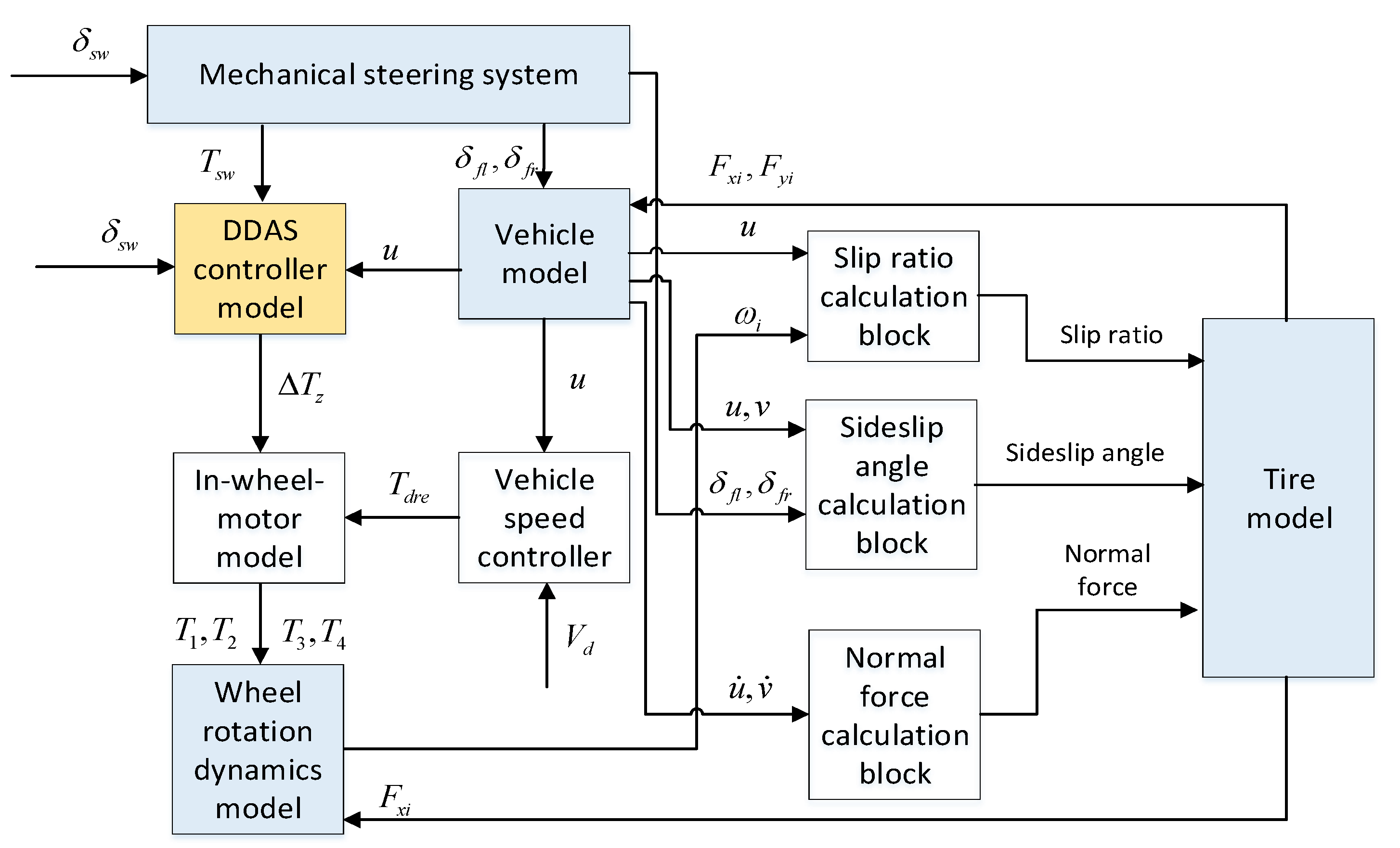
5. Simulation Analysis

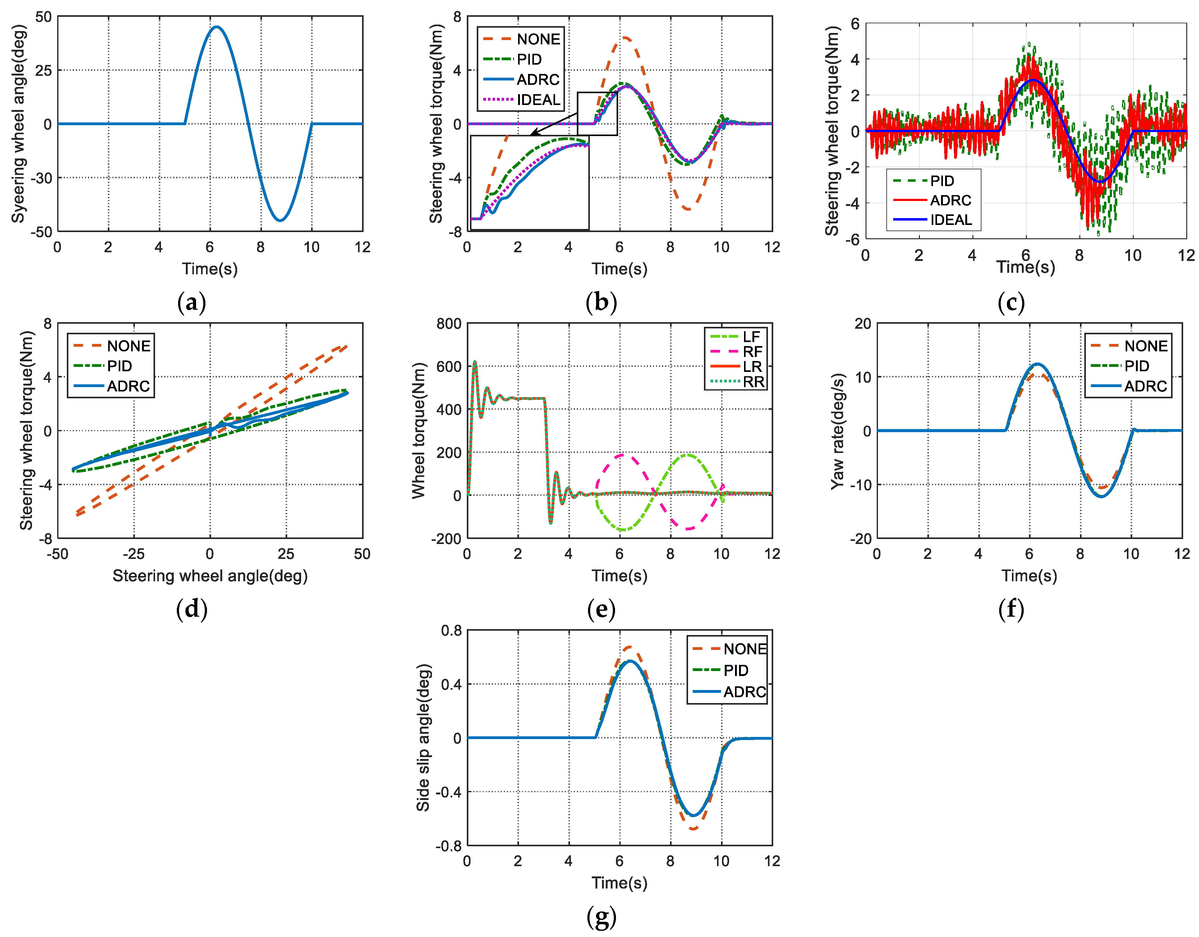
5.1. Sinusoidal Steering Wheel Angle Input Simulation

The simulation condition is selected as the sinusoidal steering wheel angle input without the driver’s steering model. First the vehicle gradually accelerates to 50 km/h and maintains this speed. As shown in Figure 11a, the vehicle is input a sinusoidal steering wheel angle at the 5th second and its amplitude and the frequency are 45 degrees and 0.2 Hz, respectively, and the road adhesion coefficient is set to 0.8. In order to verify the anti-interference performance of the proposed DDAS controller, the white noise model is used to imitate the sensor noise of the steering wheel torque, of which power and frequency are 0.01 and 27.5 Hz, respectively. During this procedure, two different controllers―one a PID controller, and the other the proposed ADRC controller―are used as two comparison simulation cases to control the DDAS system to assist the driver to steer the car. For better comparing their performance, the three parameters in the PID controller are also repeatedly calibrated after multiple groups of simulations with same sinusoidal steering angle input. Figure 11 shows all the comparison simulation results.
It can be seen from Figure 11b that both PID controller and ADRC controller have achieved good performance in power assistance. The maximum torque of the steering wheel dropped from 6.3 Nm to about 2.7 Nm, a reduction by 56%, so the effect is remarkable. Moreover, it is obvious that the steering wheel torque not only has a certain leading response, but also has a little big peak value with respect to the ideal steering wheel torque when the PID controller is adopted. The trend looks good, but the tracking accuracy of PID controller is a little poor. However, as a contrast, when the ADRC controller is used, the steering wheel torque can better track the ideal steering wheel torque, and almost has no difference in peak value with respect to the ideal value. In addition, Figure 11c shows the actual steering wheel torque curve after adding white noise to the steering system. It can be seen from Figure 11c that the chatter of the actual steering wheel torque when the PID controller and ADRC controller are adopted, respectively, is similar during straight line driving conditions, while during steering conditions, it is obvious that the chatter of the actual steering wheel torque controlled by the ADRC controller is smaller than with the PID controller. During the steering stage, the function of the ADRC controller of the DDAS system is to generate steering assistance for the driver and simultaneously mitigate the system noise interference on the steering wheel torque control performance. In contrast, the linear PID controller shows difficulties in dealing with the interference. The result proves that the ADRC controller has better anti-interference ability than the PID controller.
Besides that, it can be seen from the relationship between the steering angle and the torque of the steering wheel shown in Figure 11d that the DDAS system using the PID controller and the ADRC controller can effectively reduce the steering efforts of the driver. However, the ADRC controller shows better assistance performance with smaller fluctuation and more stable steering wheel torque, indicating that the ADRC controller is significantly better than the PID controller. In addition, the wheel torque curves of the ADRC controller in Figure 11e clearly show that the right and left front wheels begin to generate differential torque, and the maximum and minimum values are 190 Nm and −180 Nm, respectively, which are within the normal range. There is almost no difference between the two controllers in yaw rate and side slip angle of center of mass as shown in Figure 11f,g.
Table 2 summarizes the root mean square (RMS) values of the steering wheel torque tracking error of these control methods. It is obvious that the tracking error RMS of the ADRC controller is much smaller than that of the PID controller, which proves that the assistance performance of the ADRC controller is significantly better than that of the PID controller.

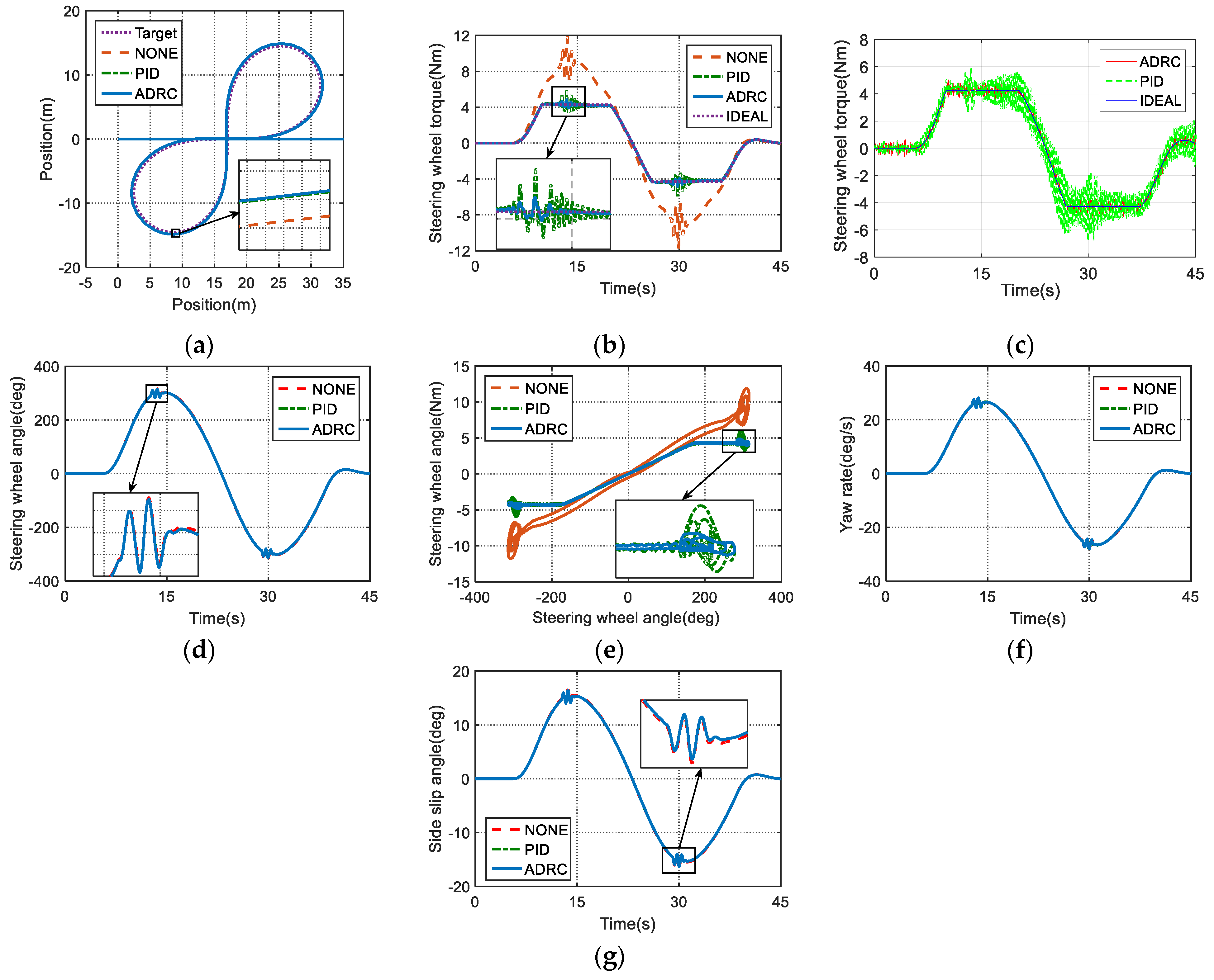
5.2. Closed-Loop Lemniscate Simulation

A driver-vehicle-road closed-loop simulation is also conducted to verify the control effect of the DDAS control strategy designed in this paper. The closed-loop simulation condition selects the standard lemniscate trajectory driving condition. The trajectory function is established according to the relevant standard, and the minimum curvature radius is set to R 0 = 6 m. In order to have a smooth steering process during the whole simulation, the standard lemniscate is rotated by 45 degrees, and a straight line segment is set before entering and after exiting the standard lemniscate road. The vehicle speed is chosen to be 10.8 km/h, and the road adhesion coefficient is 0.8. The white noise model with same amplitude and frequency as above simulation condition is also embedded into the comparing simulation. The simulation results are shown in Figure 12.
As seen in Figure 12a, the vehicle in each case with different controller can track the target trajectory better. As shown in Figure 12b, DDAS has achieved good power assisting effect with PID controller and ADRC controller, and the maximum torque of the steering wheel dropped from about 11.5 Nm to about 5.1 Nm, reduced by 50%. The effect of DDAS system on steering hand force reduction is remarkable. Furthermore, comparing to the case of PID controller, the steering wheel torque in the case of the ADRC controller can better track the ideal steering wheel torque with no advance response phenomenon, and has smaller chatter while reaching the peak value. In addition, Figure 12c shows the actual steering wheel torque result after adding white noise to the steering system. It also can be seen from Figure 12c that when the car is cornering, the influence of the sensor noise to the road feeling of the driver is greater than the car is in the straight line driving condition, especially for the case of the PID controller. Moreover, when the vehicle enters into the steering condition, the chatter of the actual steering wheel torque when using the PID controller is significantly greater than that when using the ADRC controller. The result fully proves that when the interference of the steering wheel torque sensor noise or other external or internal interference comes out, such as the changing suspension parameters as well as the nonlinear characteristics of the tires, the anti-interference ability of ADRC controller is significantly better than that of PID controller. Both Figure 12b and Figure 12c prove that the ADRC controller shows better assistance performance with smaller fluctuations and smoother steering wheel torque when compared with the PID controller. Similar results can also be seen from the cross-plot of the steering wheel angle versus steering wheel torque as in Figure 12e. By observing the time history of yaw rate shown in Figure 12f and side slip angle shown in Figure 12g, so it also can be concluded that the DDAS system does not obviously influence the stability of the vehicle which is driving all the time at constant speed on a high-adhesion road.
Table 3 is the RMS value of the steering wheel torque tracking error with respect to the ideal value of each method under lemniscate simulation. It can be concluded that both the PID controller and the ADRC controller can make the RMS of the deviation of the steering wheel torque from ideal value be much smaller compared to without control, indicating that DDAS system has a good power- assisting effect. When the ADRC controller is adopted, the RMS of the deviation of the steering wheel torque from the ideal value is 69% smaller than that of the PID controller, indicating that the power assisting effect of the ADRC controller is significantly better than that of the PID controller.

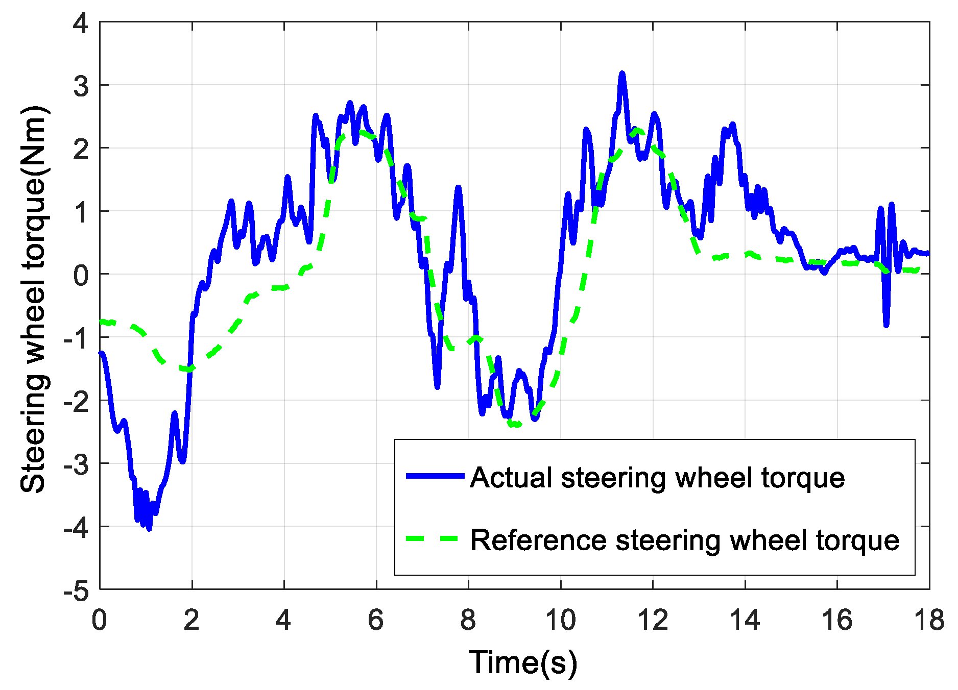
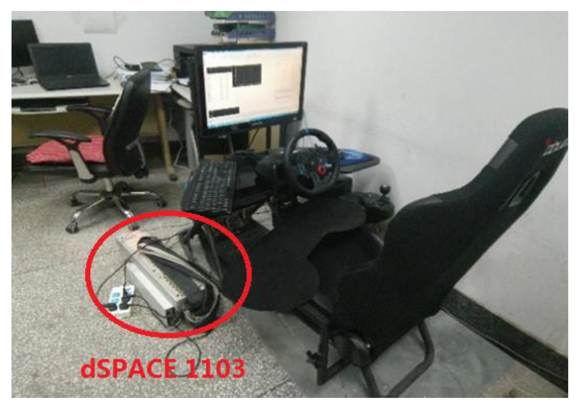
6. Hardware-in-the-Loop Experimental Validation

Taking the need for more facilities, time requirements and test yard support into account as well as the risk of losing stability while carrying out the double-lane-change test in actual vehicle experiments, a hardware-in-the-loop simulation experiment is selected to replace real vehicle testing and validate the control effect of the DDAS control strategy proposed in this paper. The testing platform of the driving simulator as shown in Figure 13 is composed of a host computer, G29 driving simulator with steering wheel angle/torque sensor and dSPACE 1103 hardware running the vehicle model.
The driver-in-the-loop experiment selects a double-lane-change test case, with a target constant-speed 40 km/h and a uniform road adhesion coefficient 0.85. The experimental results are shown in Figure 14.
It can be seen from Figure 14a that the steering wheel angle input of the drivers in three experimental cases with different controller of DDAS system or without any power steering control are similar. Figure 14b shows that DDAS has achieved very good power steering assistance effect using both the PID controller and the ADRC controller. The peak value of the steering wheel torque is reduced from 7 Nm in the case of having no any power steering to 4 Nm in the case of having the DDAS system, a reduction rate of about 43%, and the assistance effect is obvious. Moreover, when the ADRC controller is used, the steering wheel torque fluctuation is much smaller and smoother. The disturbance estimation compensator of the ADRC controller provides a compensation function for the possible disturbance from inside or outside of the steering system, thereby effectively improving the control effect of the differential drive assist steering system. The comparison result indicates that the ADRC controller is more robust when facing possible steering wheel torque or angular sensor noise, thus achieving a better road feeling for the driver than the PID controller. As shown in Figure 14d, when DDAS is applied, it is interesting that the yaw rate of the vehicle is increased, but the steering wheel angle input of the driver in this process also increases.

7. Conclusions

In this paper, a DDAS control strategy based on the steering-wheel-torque direct control is developed for the first time. Considering the disadvantages of the traditional PID controller and the particularities of the DDAS system, the ADRC technology is introduced to design the DDAS controller to reduce the steering effort of the driver and improve the driver’s road feeling simultaneously. As for the problem that the parameters of the ADRC controller are difficult to set, the simulated annealing algorithm is used to optimize the controller parameters offline. Finally, a variety of working conditions are selected to verify the developed strategy by using the vehicle model established in this paper. All the simulation and experiment results show that compared with the PID controller commonly used in DDAS, the proposed ADRC controller developed in this paper can not only reduce the steering effort of the driver obviously like previous conventional control method, but also have better control performance in tracking accuracy and smooth road feeling of the driver.

Author Contributions

J.W. administrated the whole research and revised the manuscript as the scientific project leader. X.W. implemented the experiments and wrote the initial manuscript. Z.L. designed the control algorithm model and performed the simulation. F.A. supervised the writing and critically reviewed. All authors have read and agreed to the published version of the manuscript.

Funding

This research was funded by the National Natural Science Foundation of China under Grant 51875235, and in part by the Jilin Province Science and Technology Development Project under Grant 20180414011GH and 20190802015ZG.

Acknowledgments

The authors are grateful to the National Natural Science Foundation of China and all the reviewers for their constructive comments.

Conflicts of Interest

The authors declare no conflict of interest.

Nomenclature

r σ scrub radius
r w tire rolling radius
N L transmission ratio of the rack translation to the knuckle arm angular displacement
I w moment of inertia of the wheel about its central axis
F x i , F y i ( i = 1 , 2 , 3 , 4 ) the longitudinal and lateral forces of the left front wheel, the right front wheel, the left rear wheel, and the right rear wheel respectively
m the mass of the whole vehicle
u the longitudinal speed of the body centroid
v the longitudinal speed of the body centroid
ω r the yaw rate of the vehicle body
I z the inertia of the body around the Z axis
C D the air resistance coefficient
ρ the air density
A the frontal area
δ f l , δ f r steering angles of the left front wheel and the right front wheel
L f the distance from the body centroid to the front axle
L r the distance from the body centroid to the rear axle
B the wheelbase
T s w the steering wheel torque
B C the damping of the steering column
J C equivalent inertia of steering wheel and column
δ s w steering wheel angle
M R the mass of the rack
B R the damping of the rack
Y R the displacement of the rack
r p the radius of the pinion
η f the forward transmitting efficiency of the steering gear
η B the backward transmitting efficiency of the steering gear
K C the torsional stiffness of the torsion bar
C F R the coulomb friction of the gear and rack
J F W i the inertia of the road wheel round their kingpin
B F W i the damping of kingpin
C F F W i the coulomb friction caused by the steerable wheels rotating the kingpin
T K L i the total torque from the kingpins of the left front wheel and the right front wheels
δ F W i the steering angle of front wheels
K S L i the torsional stiffness of the kingpin of the front wheels
M s y the alignment torque generated by the lateral force of the tire
M s x the alignment torque generated by the longitudinal force of the tire
M z z the component of the tire self-alignment torque about the kingpin
M s z the alignment torque generated by the normal force of the front axle
M t z the self-alignment torque of the tire
F z the normal force of the wheels
τ the kingpin caster angle
σ the kingpin inclination angle
ω i ( i = 1 , 2 , 3 , 4 ) the angular velocity of the wheels
T i ( i = 1 , 2 , 3 , 4 ) the driving torque of the wheels
T m * the target electromagnetic torque
ξ the motor characteristic parameter
T s w d the target steering wheel torque
Δ T z the front wheels torque difference
T d r e the total demand driving torque determined by the longitudinal driver model
V d the target speed
k p the proportional coefficient of the PID controller
k i the integral coefficient of the PID controller
k d the differential coefficient of the PID controller
R the speed factor
h the tracking step
γ 0 i ( i = 1 , 2 , 3 ) the control parameters
e the error term
ϕ the length of the linear segment
α 1 , α 2 the nonlinear factor in the fal function
e 1 the steering wheel torque error term
e 2 the steering wheel torque change rate error term
γ 1 , γ 2 the nonlinear combination coefficients
u 0 the control output of the nonlinear state error feedback
R 0 the minimum curvature radius

References

  1. Wang, J.; Wang, Q.; Jin, L.; Song, C. Independent wheel torque control of 4WD electric vehicle for differential drive assisted steering. Mechatronics 2011, 21, 63–76. [Google Scholar] [CrossRef]
  2. Zhao, W.Z.; Zhang, H. Coupling Control Strategy of Force and Displacement for Electric Differential Power Steering System of Electric Vehicle with Motorized Wheels. IEEE Trans. Veh. Technol. 2018, 10, 8118–8128. [Google Scholar] [CrossRef]
  3. Hu, C.; Qin, Y.C.; Cao, H.T. Lane keeping of autonomous vehicles based on differential steering with adaptive multivariable super-twisting control. Mech. Syst. Signal Process. 2019, 125, 330–346. [Google Scholar] [CrossRef]
  4. Kuslits, M.; Bestle, D. Modelling and control of a new differential steering concept. Veh. Syst. Dyn. 2019, 57, 520–542. [Google Scholar] [CrossRef]
  5. Peng, B.; Li, J.Q.; Sun, F.C. Research on Differential Steering Control Strategy of Distributed Electric Drive Vehicle. In Proceedings of the International Conference on Civil Engineering, Mechanics and Materials Science, Bangkok, Thailand, 17–19 May 2019. [Google Scholar]
  6. Wang, J.; Luo, Z.; Wang, Y.; Yang, B.; Assadian, F. Coordination control of differential drive assist steering and vehicle stability control for four-wheel-independent-drive EV. IEEE Trans. Veh. Technol. 2018, 67, 11453–11467. [Google Scholar] [CrossRef]
  7. Römer, J.; Kautzmann, P.; Frey, M.; Gauterin, F. Reducing Energy Demand Using Wheel-Individual Electric Drives to Substitute EPS-Systems. Energies 2018, 11, 247. [Google Scholar] [CrossRef] [Green Version]
  8. Sun, W.; Wang, J.; Wang, Q.; Assadian, F.; Fu, B. Simulation investigation of tractive energy conservation for a cornering rear-wheel-independent-drive electric vehicle through torque vectoring. Sci. China Technol. Sci. 2018, 61, 257–272. [Google Scholar] [CrossRef]
  9. Han, J. Auto Disturbances Rejection Control Technique; National Defense Industry Press: Beijing, China, 2008. [Google Scholar]
  10. Esmailzadeh, E.; Vossoughi, G.R.; Goodarzi, A. Dynamic modeling and analysis of a four motorized wheels electric vehicle. Veh. Syst. Dyn. 2001, 35, 163–194. [Google Scholar] [CrossRef]
  11. Pang, D.Y.; Jang, B.C.; Lee, S.C. Steering Wheel Torque Control of Electric Power Steering by PD-Control; ICCAS: Kintex, Korea, 2005. [Google Scholar]
  12. Badawy, A.; Zuraski, J.; Bolourchi, F.; Chandy, A. Modeling and Analysis of an Electric Power Steering System; International Congress and Exposition: Detroit, MI, USA, 1999. [Google Scholar]
  13. Salaani, M.K.; Heydinger, G.J.; Grygier, P.A. Closed Loop Steering System Model for the National Advanced Driving Simulator; 2004 SAE World Congress: Detroit, MI, USA, 2004. [Google Scholar]
  14. Guo, K. Vehicle Handling Dynamics; Jilin Science Press: Changchun, China, 1991. [Google Scholar]
  15. Jin, L.Q.; Song, C.X.; Peng, Y.H. Theory for Optimization Design of Steer Wheel Alignment Based on Returnability and Handiness. Trans. Chin. Soc. Agric. Mach. 2006, 37, 20–23. [Google Scholar]
  16. Wang, Q.; Wang, J.; Yan, L. Differential assisted steering applied on electric vehicle with electric motored wheels. J. Jilin Univ. (Eng. Technol. Ed.) 2009, 39, 1–6. [Google Scholar]
  17. Bakker, E.; Nyborg, L.; Pacejka, H.B. Tyre Modeling for Use in Vehicle Dynamics Studies; Society of Automotive Engineers: Warrendale, PA, USA, 1987. [Google Scholar]
  18. Shen, R.; Lin, Y.; Tai, X. Research on Modeling and Compensation Control Strategy of Electric Power Steering System. Trans. Chin. Soc. Agric. Mach. 2007, 38, 5–9. [Google Scholar]
  19. Bertollini, G.P.; Hogan, R.M. Applying Driving Simulation to Quantify Steering Effort Preference as a Function of Vehicle Speed; International Congress and Exposition: Detroit, MI, USA, 1999. [Google Scholar]
  20. Green, P.; Gillespie, T.; Reifeis, S. Subjective Evaluation of Steering Effort Levels; The University of Michigan Transportation Research Institute: Ann Arbor, MI, USA, 1984. [Google Scholar]
  21. Toffin, D.; Reymond, G.; Kemeny, A.; Droulez, J. Role of steering wheel feedback on driver performance: Driving simulator and modeling analysis. Veh. Syst. Dyn. 2007, 45, 375–388. [Google Scholar] [CrossRef]
  22. Shen, R.; Lin, Y.; Tai, X. Steering torque direct control strategy for vehicle electric power steering system. J. Jilin Univ. (Eng. Technol. Ed.) 2007, 37, 504–508. [Google Scholar]
  23. Ahi, B.; Haeri, M. Linear Active Disturbance Rejection Control from the Practical Aspects. IEEE/ASME Trans. Mechatron. 2018, 23, 2909–2919. [Google Scholar] [CrossRef]
  24. Han, J. Auto Disturbances Rejection Control Technique. Front. Sci. 2007, 1, 24–31. [Google Scholar]
  25. Zheng, Q.; Dong, L.; Lee, D.H. Active Disturbance Rejection Control for MEMS Gyroscopes. IEEE Trans. Control Syst. Technol. 2009, 17, 1432–1438. [Google Scholar] [CrossRef]
  26. Wang, K. Research on Active Disturbance Rejection Control of Full Vehicle Active Suspension Based on Adaptive Genetic Algorithm; Jilin University: Changchun, China, 2017. [Google Scholar]
  27. Zhao, J. Optimization Technology and MATLAB Optimization Toolbox; Mechanical Industry Press: Beijing, China, 2011. [Google Scholar]
Figure 1. Working principle diagram of a differential drive assist steering (DDAS) system.
Energies 13 02647 g001
Figure 2. Steering wheel torque.
Energies 13 02647 g002
Figure 3. The whole block diagram of independent-wheel-drive electric vehicle model.
Energies 13 02647 g003
Figure 4. Vehicle body dynamic model.
Energies 13 02647 g004
Figure 5. 4-DoF mechanical steering system model.
Energies 13 02647 g005
Figure 6. Wheel rotation dynamic model.
Energies 13 02647 g006
Figure 7. Steering-wheel-torque direct control strategy.
Energies 13 02647 g007
Figure 8. The ideal steering wheel torque map.
Energies 13 02647 g008
Figure 9. The structure of ADRC controller of DDAS system.
Energies 13 02647 g009
Figure 10. Optimization process.
Energies 13 02647 g010
Figure 11. Sinusoidal input simulation: (a) Steering wheel angle; (b) Steering wheel torque; (c) Steering wheel torque with white noise; (d) Cross-plot of steering wheel angle and torque; (e) Wheel torque of ADRC controller; (f) Yaw rate; (g) Side slip angle.
Energies 13 02647 g011
Figure 12. Closed-loop lemniscate simulation: (a) Vehicle trajectory; (b) Steering wheel torque; (c) Steering wheel torque with white noise; (d) Steering wheel angle; (e) Cross-plot of steering wheel angle and torque; (f) Yaw rate; (g) Side slip angle.
Energies 13 02647 g012
Figure 13. Testing simulator platform based on dSPACE hardware.
Energies 13 02647 g013
Figure 14. Simulator experiment results: (a) Steering wheel angle; (b) Steering wheel torque; (c) Wheel torque of ADRC controller; (d) Yaw rate.
Energies 13 02647 g014
Table 1. ADRC controller parameter optimization
Parameters γ 01 γ 02 γ 03 γ 1 γ 2 b 0
Initial value4506001000−350301
Optimal value700.955997.714903.922−425.8930.3722.801
Table 2. The RMS comparison of the steering wheel torque following error in sinusoidal input simulation.
PerformanceUncontrolledPIDADRC
T s w T s w d (Nm)1.6740.27950.0867
Table 3. The RMS comparison of the steering wheel torque tracking errors in lemniscate simulation.
PerformanceUncontrolledPIDADRC
T s w T s w d (Nm)2.1760.21060.07809

