Article

Discussion on Determination Method of Long-Term Strength of Rock Salt

1
Research Institute of Petroleum Exploration and Development, Langfang 065007, China
2
CNPC Key Laboratory of Oil and Gas Underground Storage Engineering, Langfang 065007, China
3
State Key Laboratory of Hydraulic and Mountain River Engineering, College of Water Resource & and Hydropower, Sichuan University, Chengdu 610065, China
4
School of Civil Engineering, Architecture and Environment, Xihua University, Chengdu 610039, China
*
Author to whom correspondence should be addressed.
Energies 2020, 13(10), 2460; https://doi.org/10.3390/en13102460
Submission received: 12 April 2020 / Revised: 7 May 2020 / Accepted: 11 May 2020 / Published: 13 May 2020

Abstract

:
Due to the extremely low permeability and the excellent creep behavior, rock salt is the optimal surrounding rock of underground energy storage. The long-term safe operation of the rock salt energy storage is closely related to the creep behavior and long-term strength of rock salt, but few researches focus on the long-term strength of rock salt. In order to more accurately predict the long-term strength of rock salt, the isochronous stress–strain curve method and the volume expansion method for determining the long-term strength were analyzed and discussed based on axial compression tests and axial creep tests. The results show that the isochronous stress–strain curve method is intuitive but will greatly increase the test cost and test time to obtain a satisfactory result. The volume expansion method is simple, but the long-term strength obtained according to the inflection point of volumetric strain is much greater than the actual long-term strength of rock salt. Therefore, a new method applicable to rock salt was proposed based on the evolution of damage in rock salt in this paper, which takes the corresponding stress value at the damage initiation point as the long-term strength. The long-term strength determined by this method is consistent with that by the isochronous stress–strain curve method. The method is more economical and convenient and aims to provide a reference for the long-term stability study of underground salt caverns.

1. Introduction

Underground storage of energy is an economical and safe way for storage of huge energy, like oil, natural gas, hydrogen, pressured air etc. Rock salt has extremely low permeability (permeability coefficient is less than 10–20 m2) [1,2,3,4] and excellent creep behavior, which can ensure the tightness of underground energy storage. Due to the stable mechanical properties and the ability to recover from damage of rock salt, it is able to adapt to pressure changes during the operation of the reservoir, which makes rock salt become an internationally recognized ideal place for underground energy storage [5]. The long-term safe operation of rock salt underground storage must inevitably involve the time-dependent properties of rock salt. The study of rock rheological mechanics is to explore the law of rock stress, strain and failure with time [6,7,8,9]. The rheology of rock salt includes the long-term strength, creep, relaxation, elastic aftereffect, etc. The most important of these properties are long-term strength and creep, meaning that the two key issues in the long-term safe operation of rock salt underground storage are the long-term strength and creep characteristics of rock salt.
Since the world’s first salt cavern gas storage was built in 1959, many research have been done on the mechanical behavior, creep characteristics and underground storage technology of rock salt, and many useful results have been obtained [10,11,12,13,14]. Rock salt is a kind of soft rock with large deformation and low strength [15,16,17,18,19,20]. It exhibits the property of strain softening under low confining pressure and exhibits the property of strain hardening under high confining pressure. The creep properties of rock salt are strongly related to temperature [21,22], stress levels [23,24,25,26], loading method [10,11,27,28] and loading paths [23,29,30]. When the temperature and stress levels are constant, the creep rate of the stable creep phase remains almost constant, but during the accelerated creep phase, the creep rate continues to increase, causing the failure of the rock salt. In addition, the creep deformation and creep rate of rock salt are greatly affected by confining pressures [25,26], but as the confining pressure increases, the effect of confining pressure on the steady creep rate gradually decreases.
At present, the research on the mechanics and creep characteristics of rock salt is mainly focused on the short-term strength and creep characteristics; there are few reports on the long-term strength of rock salt. The ability of rock materials to resist damage under long-term loading and short-term loading is different and the strength of rock will decrease with the increase of loading time [31,32,33]. Therefore, when designing some structures with a long service life, such as rock salt energy underground gas storage, it is necessary to consider the long-term strength rather than the short-term strength as its design index. The research on the long-term strength of rock salt is not only of great significance to the construction of rock salt underground gas storage and long-term operational safety, but also has a positive effect on the development of the creep theory of rock salt.
In general, there are two major methods for determining the long-term strength of rocks [34]: (1) The direct method obtains the long-term strength through long-term constant-load creep tests under various stress levels. The long-term strength obtained by this method is relatively realistic, but it requires multiple specimens to be loaded at different stress levels and the test duration is long with great expense. (2) The indirect method determines the long-term strength of rock according to some mechanical properties during the deformation and failure process, such as the volume expansion method which determines the long-term strength by the volume expansion point. This method is simple to operate, but usually the stress at which the damage generates is lower than the stress at the volume expansion point, resulting in a higher long-term strength. Therefore, in this paper, based on uniaxial compression tests and uniaxial creep tests of rock salt, the long-term strength of rock salt determined by the isochronous stress–strain curve method and the volume expansion method were compared and discussed. Furthermore, an economical and convenient method based on damage mechanics for determining long-term strength of salt rock is proposed, which can provide a reference for the long-term stability study of the underground salt cavern storage.

2. Experimental Method

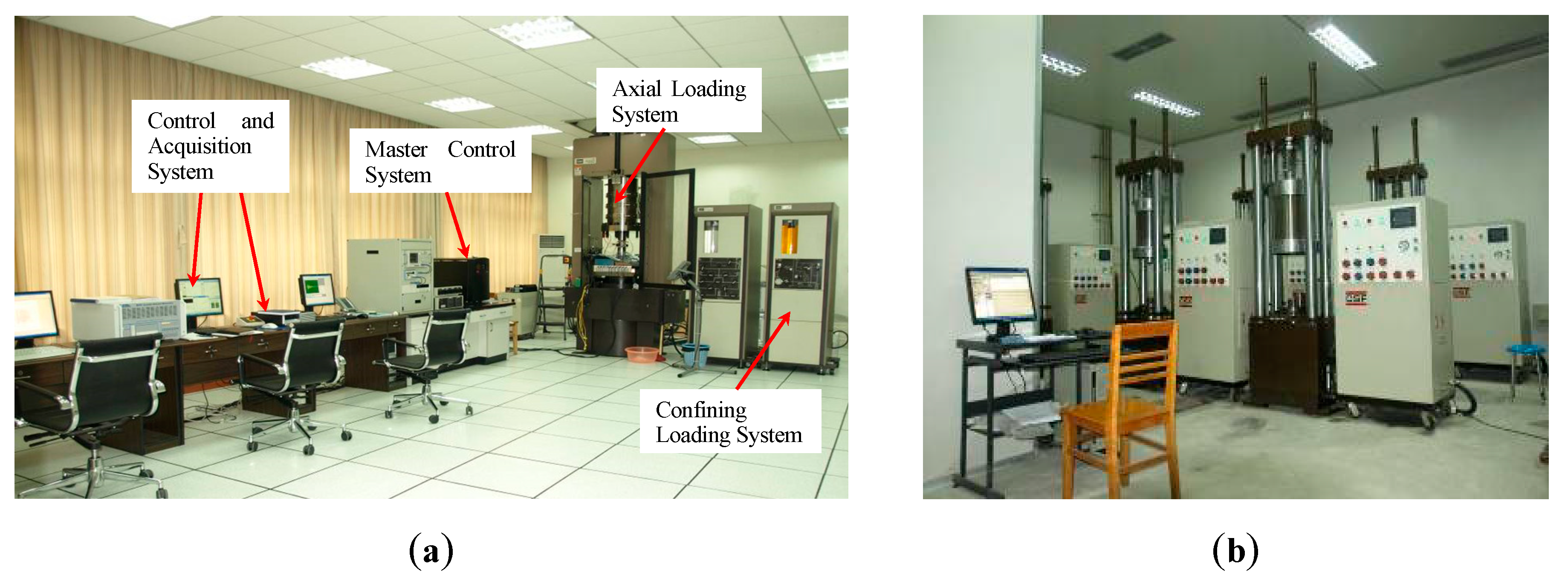
2.1. Equipment and Specimen
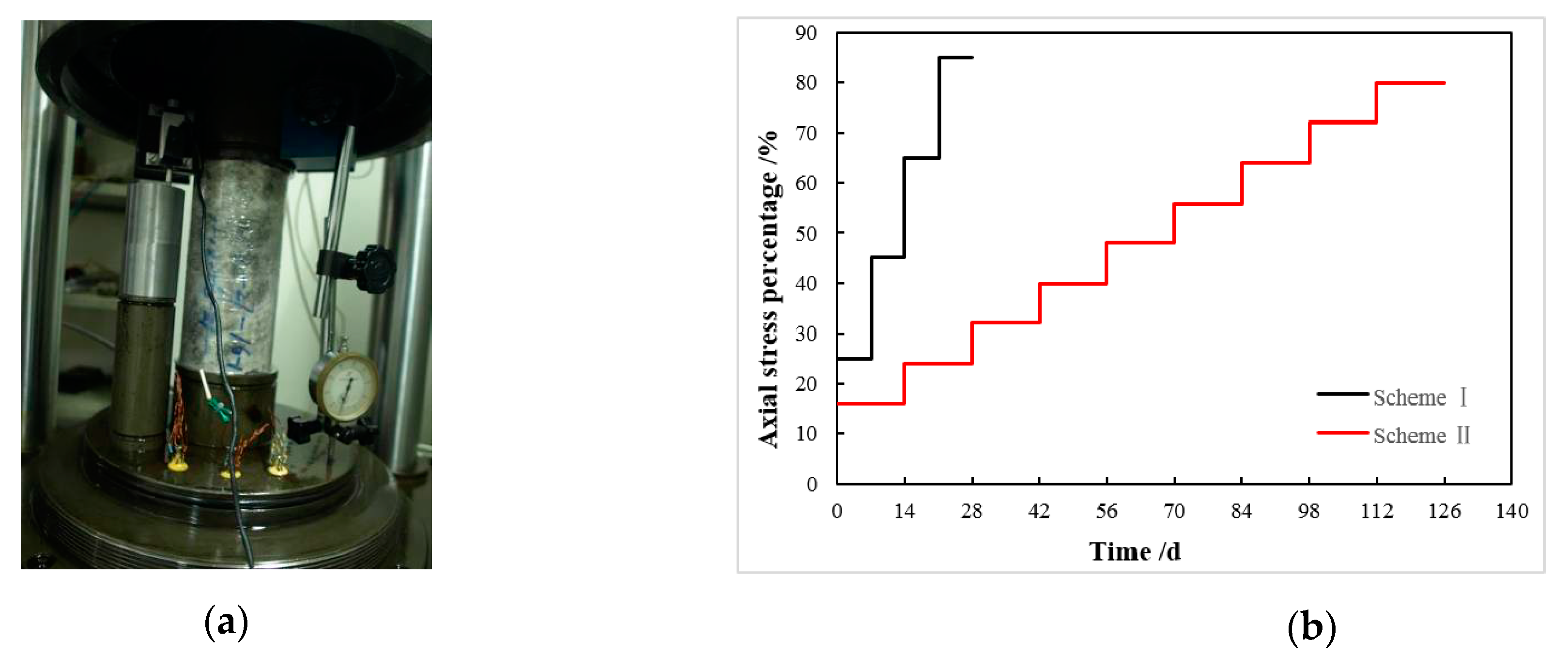
The uniaxial compression tests were conducted in Rock Mechanics Laboratory of Sichuan University, using the MTS815 Flex Test GT rock mechanics test system (Figure 1a). The maximum axial loading is 4600 KN. The measuring range of the axial deformation is from −4 to 4 mm and the measuring range of the lateral deformation is from −2.5 to 8 mm, both with the measurement and control precision of 0.5% RO.
The uniaxial creep tests were carried out on the program-controlled rheometers in Sichuan University (Figure 1b). This equipment can perform both uniaxial and triaxial creep tests with a maximum axial loading capacity of 60 t and a maximum confining pressure of 30 MPa. During the test, the external environment (laboratory temperature 20 ± 2 °C) can be kept basically unchanged. Both the displacement sensors and the dial indicator with the precision of 1% were used to collect and record the test data.
The rock salt samples used in the laboratory tests were taken from a proposed salt cavern for gas storage in China at depth of 2000 m. The rock salt was mainly composed of approximately 1 ~ 8% CaSO4, 0.82 ~ 5.38% Na2SO4, 82.87 ~ 95% NaCl and 1.7 ~ 5.63% muddy insoluble matter. Specimens were prepared following the Standard for Test Method of Engineering Rock Mass in China (GB/T50266-2013) [35], with the dimension of Φ80 mm × H160 mm.

2.2. Test Procedure

In order to discuss the method for determining the long-term strength of rock salt, the uniaxial compressive tests and the uniaxial creep tests were carried out on rock salt specimens.
The uniaxial compression tests were performed on the MTS815 Flex Test GT rock mechanics test system. During the test, the compaction stage and the elastic deformation stage were controlled by axial loads with the loading rate of 30 kN/min. Then it was switched to the axial displacement control with the loading rate of 0.1 mm/min. The uniaxial loading test device is shown in Figure 2a. The axial deformation was measured by the axial extensometer with a measuring range from −4 to 4 mm and the lateral deformation was measured by the circumferential extensometer with a measuring range from −2.5 to 8 mm. The volumetric strain was obtained by the axial strain ε1 and the lateral strain ε3 using the following formula:
ε v = ε 1 + 2 ε 3 ,
where, ε1 is the axial strain, ε3 is the lateral strain, and εv is the volumetric strain.
Through the uniaxial compression test, the stress–strain curves (Figure 2b) of rock salt were obtained, and the average uniaxial compressive strength of the rock salt specimens was about 25 MPa.
The uniaxial creep tests were carried out by using the program-controlled rheometers (Figure 3a). The graded loading method (Figure 3b) was adopted so that the different stress levels were sequentially applied to the same rock specimen. This method can overcome the error caused by the discreteness of specimens; this method shortened the test time. According to the uniaxial compressive strength and the stress–strain curves of the rock salt obtained from the uniaxial compression tests, the stress corresponding to the starting point of volume expansion usually did not exceed 70% of the short-term strength. Therefore, a graded loading scheme recorded as Scheme I was designed with four loading stages and a duration of 7 h for each stage, which is shown in Table 1. Compared with Scheme I, another loading scheme recorded as Scheme II was designed. Scheme II increased the number of test loading stages, reduced the stress difference at each stage, and extended the duration of each stage to compare and explore the impact of loading schemes on the long-term strength.
The creep duration curves of rock salt under two loading schemes were obtained through creep tests (Figure 4). Scheme I was subjected to the predetermined loading stress to the last stage where creep failure occurred, but Scheme II was subjected to the loading stress to the eighth stage where creep failure occurred. The creep curves of the two rock salt specimens under the same scheme have high consistency. The creep curves at the first three stress levels under the Scheme I were characterized by initial creep and steady-state creep, and began to exhibit accelerated creep at the fourth stress level where creep failure occurred. The failure stress is 21.25 MPa, which is 85% of the axial compression strength. Under Scheme II, the creep curves at the first five stages were characterized by initial creep and steady-state creep. The accelerated creep did not appear until the sixth loading stage. At the last loading stage, there was a significant nonlinear accelerated creep phase, where creep failure occurred. The failure stress is 18 MPa, which is the 72% of the axial compression strength and less than the failure stress under the scheme. It indicates that with the duration of the loading stress applied to rock salt increasing, the creep failure stress of rock salt gradually decreases.

3. Discussion of Method for Determining Long-Term Strength

3.1. Isochronous Stress–Strain Curve Method

The isochronous stress–strain curve method is currently the most commonly used method to determine the long-term strength of rocks, which has been introduced into the relevant rock mechanics test specifications [36]. This method is based on a set of creep curves at different stress levels, and takes the inflection points corresponding to the curve clusters of the relationship between the creep strain and stress at the same time to determine the long-term strength. The inflection points of the isochronous curves mark the transformation of the rock deformation from the viscoelastic phase to the viscoplastic phase. At this time, the internal structure of the rock undergoes important changes, and internal damage occurs. The stress corresponding to the asymptote of the curve formed by these inflection points is the long-term strength, which is marked as σ∞. The method using the isochronous stress–strain curves for determining the long-term strength is shown in Figure 5.
According to the creep curves obtained from the axial creep tests, the creep strain and the axial stress at the same time t in the creep curves under different stress levels were taken to obtain the isochronous stress–strain curves. Figure 6 shows the isochronous stress–strain curves of rock salt under Scheme I and Scheme II. As shown in Figure 6, with the development of time and the increase of stress, the non-linear characteristics of isochronous curves are gradually obvious, showing that the curves begin to bend and the curve clusters change from dense to sparse. However, due to the large stress difference between the two stress levels in Scheme I, the inflection point is not obvious and is not clear enough to accurately determine the stress corresponding to the inflection point. The stress range corresponding to the inflection point (Figure 6a,b) is 14–15 MPa, which makes the determination of the long-term strength relatively arbitrary. Moreover, it can be seen from the isochronous stress–strain curves that the curves after the turning point still has a certain slope, and no curves parallel to or nearly parallel to the x-axis have been obtained. Therefore, the long-term strength obtained from the creep laboratory test is still higher than the actual long-term strength of rock salt. Based on the curves in Figure 6a,b, if the long-term strength of rock salt is determined as 14.5 MPa, it is 58% of the uniaxial compressive strength. In Scheme II, due to the decrease of the stress difference between the two stress levels and the increase of the loading duration, there are obvious inflection points on the isochronous curve clusters of the two specimens (Figure 6c,d). The stress values corresponding to the inflection points are both 12 MPa. It can be determined that the measured long-term strength is 12 MPa, which is 48% of the uniaxial compressive strength. The above results show that obvious inflection points and satisfactory results can be obtained by increasing the number of loading stages and extending the loading time.
By carrying out creep tests on rock salt with increasing loading stages and extending loading time, the results closer to the actual long-term strength values can be obtained. It is foreseeable that when the loading time of each stage is infinitely long, the damage stress will approach the long-term strength. Therefore, in the laboratory test, reasonably increasing the number of loading stages and extending the loading time not only can make the inflection point on the isochronous curves more obvious, but also can obtain results closer to the actual value of long-term strength.

3.2. Volume Expansion Method

Based on the previous section results, it can be known that the deviation in determining the long-term strength is large if creep tests are carried out according to the stress ratio loading with less loading stages and shorter loading duration. When the long-term strength of rock salt cannot be determined by the isochronous stress–strain curve method, there is another more commonly used method to determine the long-term strength of rocks, which is the volume expansion method.
The creep is primarily driven by slow microcrack growth, which leads to the expansion of the volume. Based on the time-dependent cracking characteristics, the volume strain of rock materials during the deformation and failure process can be divided into the following four stages [37,38,39,40,41]: (1) the crack closing phase, during which the rock volume decreases, and the volumetric strain rate is positive; (2) the elastic compression phase, during which the rock volume decreases linearly, and the volumetric strain rate is positive and constant; (3) the crack stable growth phase, during which the volumetric strain rate is positive but gradually decreases; and (4) the crack unstable growth phase, during which the volumetric strain rate is negative and the volume expansion occurs, causing the rock failure (Figure 7). Martin [37] defined the stress level corresponding to the starting point of the fourth stage as the crack damage stress. The volume strain was reversed at this point, which indicated that the rock volume expanded. He pointed out that the crack damage stress was an indicator that could reflect the long-term strength of rocks.
Based on the axial compression tests, Figure 8 shows the stress-volumetric strain curves of rock salt. As shown in Figure 8, under the axial compression, the volumetric strain curve of rock salt has undergone the phase of compaction, elasticity, and crack stable growth; and then appears an expansion starting point (inflection point of volumetric strain), where the volumetric strain is about 0.2%. According to the volume expansion method, the stress corresponding to the inflection point of volumetric strain can be determined as the long-term strength, which is 17.7 MPa and is 70% of the short-term compressive strength (the axial compression strength). It is noticed that the long-term strength of rock salt determined by the volume expansion method is significantly higher than that determined by the isochronous stress–strain curve method in Scheme I, indicating that the long-term strength of rock salt determined according to the inflection point of volumetric strain has a greater deviation from the actual long-term strength of rock salt.

3.3. Discussion

According to rock damage mechanics, there is generally a damage stress threshold for rock damage. When the stress level is lower than this value, no damage occurs. Otherwise, when the stress level exceeds this limit, damage starts to accumulate and develop. The generation and evolution of damage is manifested as the emergence and growth of cracks in rock, so the damage initiation point corresponds to the crack growth start point. Based on elastic mechanics, the tangent bulk modulus K is proportional to the average stress σm at the elastic deformation stage, and then the damage initiation point can be determined by the following formulas:
σ m = σ 1 + σ 2 + σ 3 3
K = E 3 ( 1 2 μ )
ε v = σ m K
where, σm, σ1, σ2 and σ3 are the average stress, maximum principal stress, intermediate principal stress, and minimum principal stress respectively. In this paper, the values of σ2 and σ3 are both 0 under the uniaxial stress conditions; K and E are the tangent bulk modulus and elastic modulus; μ is Poisson’s ratio; and εv is volumetric strain.
The average and tangent are the two methods that ISRM (International Society for Rock Mechanics and Rock Engineering) recommends to determine the Young’s modulus from the UCS (Uniaxial Compressive Strength) test, and there is good consistency of average and tangent modulus [42]. Therefore, according to the stress and strain values on the straight section of the stress–strain curve obtained by the previous short-term uniaxial compression test (Figure 2b), the elastic modulus E and the Poisson’s ratio μ of the rock salt specimen were calculated following the Standard for Test Method of Engineering Rock Mass in China (GB/T50266–2013) [35]. The elastic modulus E is 6.21 GPa and Poisson’s ratio μ is 0.12. Then the linear elastic volume strain curves can be obtained by using Equations (2–4), and the tangent point of the linear elastic volume strain curve and the volume strain curve is the damage initiation point. The location of the damage initiation point is shown in Figure 8. It is found that the stress corresponding to the damage initiation point is 12.17 MPa, which is the same as the long-term strength obtained by the isochronous stress–strain curve method in the creep test Scheme II. Based on this interesting phenomenon, the long-term strengths obtained by the isochronous stress–strain curve method in the two schemes, the stress corresponding to the damage initiation point and the stress corresponding to the inflection point of volumetric strain are listed in Table 2. The long-term strengths of rock salt determined by the volume expansion method and the isochronous stress-strain curve method in Scheme I are both significantly higher than that determined by the isochronous stress-strain curve method in Scheme II. As analyzed in Section 3.1, the long-term strength determined by the isochronous stress–strain curve method in Scheme II is more reasonable and appropriate, which means the long-term strength determined by the damage initiation point method is also acceptable. Therefore, it can be considered that when using the stress-volumetric strain curves to predict the long-term strength of rock salt, the corresponding stress at the damage initiation point can be taken as the long-term strength.
According to the research literature on the long-term strength of rocks, the long-term strength of most rocks is between 60% and 80% of the short-term compressive strength [43,44,45]. But the ratio of the long-term strength of the rock salt to the short-term compressive strength is lower than the ratios of most rocks, which are less than 50% [46,47]. The long-term strength determined by the damage initiation point method proposed in this paper is 48% of the short-term compressive strength, which proves the applicability of this method to salt rock.
By comparing the above three methods, the isochronous stress–strain curve method is simple and intuitive, but it is necessary to effectively increase the number of loading stages and extend the loading duration in order to obtain more accurate long-term strength, which will greatly increase the test cost and test time. The volume expansion method requires simple test conditions, but the long-term strength obtained according to inflection point of volumetric strain is much greater than the actual long-term strength of rock salt. The damage initiation point method can not only get a theoretical value close to the real value, but also saves much manpower and material resources.

4. Conclusions

Based on the axial compression tests and the axial creep tests, the isochronous stress–strain curve method and volume expansion method for determining the long-term strength of rock salt were analyzed and discussed. Some conclusions are obtained as follows:
(1)
The long-term strength determined by the volume expansion method is higher than the actual value of rock salt, which is not applicable to rock salt.
(2)
The isochronous stress–strain curve method is reasonable and applicable to rock salt for the determination of the long-term strength. However, to get more accurate long-term strength values, more loading stages and a longer test time are necessary.
(3)
A method which take the corresponding stress value at the damage initiation point as the long-term strength was proposed based on the evolution of damage in rock salt. The long-term strength determined by this method is consistent with that by the isochronous stress–strain curve method, indicating that this method is also applicable to rock salt.
The new method proposed in this paper can provide some reference for the study on the long-term strength of rock salt. However, it should be noted that due to the complexity of the fabric of rock salt and the influence of impurities, this method still requires much experimental data for further verification and in-depth research.

Author Contributions

Conceptualization, G.D. and J.L.; data curation, Z.Z.; formal analysis, L.W.; funding acquisition, J.L.; investigation, Z.W.; methodology, G.D.; resources, G.D.; writing—original draft, G.D.; writing—review and editing, J.L. and L.W. All authors have read and agreed to the published version of the manuscript.

Funding

This research was funded by National Natural Science Foundation of China, grant number 51874202; Sichuan Youth Fund, grant number 2017JQ0003; National Key Research and Development Project, grant number 2017YFC0805800 and National Ten Thousand Talent Program.

Acknowledgments

The authors would also like to express our deep appreciation for the support from the Ten Thousand Plan Youth Top Project proposed by the Organization Department of the Central Committee of the CPC.

Conflicts of Interest

The authors declare no conflict of interest.

References

  1. Cosenza, P.; Ghoreychi, M.; Bazargan-Sabet, B.; De Marsily, G. In situ rock salt permeability measurement for long term safety assessment of storage. Int. J. Rock Mech. Min. 1999, 36, 509–526. [Google Scholar] [CrossRef]
  2. Stormont, J.C. Conduct and interpretation of gas permeability measurements in rock salt. Int. J. Rock Mech. Min. 1997, 34, 303.e1–303.e11. [Google Scholar] [CrossRef]
  3. Fokker, P.A. The Behavior of Salt and Salt Caverns. Ph.D. Thesis, Delft University of Technology, Delft, The Netherlands, 1995. [Google Scholar]
  4. Trippetta, F.; Collettini, C.; Vinciguerra, S.; Meredith, P.G. Laboratory measurements of the physical properties of Triassic Evaporites from Central Italy and correlation with geophysical data. Tectonophysics 2010, 492, 121–132. [Google Scholar] [CrossRef]
  5. Trippetta, F.; Collettini, C.; Barchi, M.R.; Lupattelli, A.; Mirabella, F. A multidisciplinary study of a natural example of a CO2 geological reservoir in central Italy. Int. J. Greenh. Gas Control 2013, 12, 72–83. [Google Scholar] [CrossRef]
  6. Goodman, R.E. Introduction to Rock Mechanics; Wiley: New York, NY, USA, 1989. [Google Scholar]
  7. Xie, H.P.; Chen, Z.H. Rock Mechanics; Science Press: Beijing, China, 2004. [Google Scholar]
  8. Mogi, K. Experimental Rock Mechanics; CRC Press: London, UK, 2006. [Google Scholar]
  9. Jaeger, J.C.; Cook, N.G.W.; Zimmerman, R.W. Fundamentals of Rock Mechanics, 4th ed.; Blackwell Publishing: Hoboken, NJ, USA, 2007. [Google Scholar]
  10. Hunsche, U.; Schulze, O. Effect of humidity & confining pressure on creep of rock salt. Ser. Rock Soil Mech. 1996, 20, 237–248. [Google Scholar]
  11. Cristescu, N.D.; Paraschiv, I. Creep, damage and failure around large rectangular-like caverns and galleries. Mech. Cohesive Frict. Mater. 1996, 1, 165–197. [Google Scholar] [CrossRef]
  12. Yang, C.H.; Daemen, J.J.K.; Yin, J.H. Experimental investigation of creep behavior of salt rock. Int. J. Rock Mech. Min. Sci. 1999, 36, 233–242. [Google Scholar] [CrossRef]
  13. Asanov, V.A.; Pan’kov, I.L. Deformation of salt rock joints in time. J. Min. Sci. 2004, 40, 355–359. [Google Scholar] [CrossRef]
  14. Wu, W.; Yang, Y.H.; Hou, Z.M. Investigations on studied situations associated with mechanical aspects and development for underground storage of petroleum and natural gas in rock salt. Chin. J. Rock Mech. Eng. 2005, 24, 5561–5568. [Google Scholar]
  15. Farmer, I.W.; Gilbert, M.J. Dependent strength reduction of rock salt. In Proceedings of the 1st Conference on the Mechanical Behavior of Salt, State College, PA, USA, 9–11 November 1981; Trans. Tech. Publications: Clausthal, Germany, 1984; pp. 4–18. [Google Scholar]
  16. Liang, W.; Zhao, Y. Experimental study on mechanical characteristics of thenardite rock salt. Chin. J. Rock Mech. Eng. 2004, 23, 391–394. [Google Scholar]
  17. Liang, W.G.; Yang, C.H.; Zhao, Y.S.; Dusseault, M.B.; Liu, J. Experimental investigation of mechanical properties of bedded salt rock. Int. J. Rock Mech. Min. Sci. 2007, 44, 400–411. [Google Scholar] [CrossRef]
  18. De Paola, N.; Faulkner, D.R.; Collettini, C. Brittle versus ductile deformation as the main control on the transport properties of low-porosity anhydrite rocks. J. Geophys. Res. Solid Earth 2009, 114, B06211. [Google Scholar] [CrossRef]
  19. Grindrod, P.M.; Heap, M.J.; Fortes, A.D.; Meredith, P.G.; Wood, I.G.; Trippetta, F.; Sammonds, P.R. Experimental investigation of the mechanical properties of synthetic magnesium sulfate hydrates: Implications for the strength of hydrated deposits on Mars. J. Geophys. Res. 2010, 115, E06012. [Google Scholar] [CrossRef] [Green Version]
  20. Trippetta, F.; Collettini, C.; Meredith, P.G.; Vinciguerra, S. Evolution of the elastic moduli of seismogenic Triassic Evaporites subjected to cyclic stressing. Tectonophysics 2013, 592, 67–79. [Google Scholar] [CrossRef]
  21. Gao, X.P.; Yang, C.H.; Wu, W.; Liu, J. Experimental studies on temperature dependent properties of creep of rock salt. Chin. J. Rock Mech. Eng. 2005, 24, 2054–2059. [Google Scholar]
  22. Liu, X.H.; Zhang, P.; Gai, F. Study on creep rule of salt rock in Sichuan region. Chin. J. Rock Mech. Eng. 2002, 21, 1290–1294. [Google Scholar]
  23. Yang, C.H.; Bai, S.W.; Wu, Y.M. Stress level and loading path effect on time dependent properties of salt rock. Chin. J. Rock Mech. Eng. 2000, 19, 270–275. [Google Scholar]
  24. Chen, F.; Li, Y.; Yang, C.; Zhang, C. Experimental study on creep behaviors of rock salt in Yunying salt mine. Chin. J. Rock Mech. Eng. 2006, 25, 3022–3027. [Google Scholar]
  25. Gao, X.P.; Yang, C.H.; Wu, W. Experimental studies on time dependent properties of rock salt. Chin. J. Rock Mech. Eng. 2005, 27, 558–561. [Google Scholar]
  26. Du, C.; Yang, C.H.; Ma, H.L.; Shi, X.L.; Chen, J. Study of creep characteristics of deep rock salt. Rock Soil Mech. 2012, 33, 2451–2456. [Google Scholar]
  27. Cristescu, N.D. A general constitutive equation for transient and stationary creep of rock salt. Int. J. Rock Mech. Min. 1993, 30, 125–140. [Google Scholar] [CrossRef]
  28. Hampel, A.; Hunsche, U.; Weidinger, P.; Blum, W. Description of the creep of rock salt with the composite model-II. Steady-State creep. In Proceedings of the 4th Conference on the Mechanical Behavior of Salt, Montreal, QC, Canada, 17–18 June 1996; Trans. Tech. Publications: Clausthal-Zellerfeld, Germany, 1998; pp. 287–299. [Google Scholar]
  29. Wang, J.B.; Liu, X.R.; Yang, X. Test on creep properties of salt rock under different loading paths. J. PLA Univ. Sci. Technol. (Nat. Sci. Ed.) 2013, 14, 517–5236. [Google Scholar]
  30. Wang, J.B. Study on the Creep Mechanical Properties of Salt Rock under Different Loading Paths and Long-Term Stability of Salt Rock Gas Storage. Ph.D. Thesis, Chongqing University, Chongqing, China, 2012. [Google Scholar]
  31. Damjanac, B.; Fairhurst, C. Evidence for a long-term strength threshold in crystalline rock. Rock Mech. Rock Eng. 2010, 43, 513–531. [Google Scholar] [CrossRef]
  32. Xu, P.; Xia, X.L. Study on creep characteristics of granite in lock zone of three gorges project. J. Yangtze River Sci. Res. Inst. 1995, 12, 23–29. [Google Scholar]
  33. Lin, Q.X.; Liu, Y.M.; Tham, L.G.; Tang, C.A.; Lee PK, K.; Wang, J. Time-dependent strength degradation of granite. Int. J. Rock Mech. Min. Sci. 2009, 46, 1103–1114. [Google Scholar] [CrossRef]
  34. Liu, X. Rock Rheology Introduction; Geological Publishing: Beijing, China, 1994. [Google Scholar]
  35. (GB/T50266-2013) National Standards Compilation Group of People’s Republic of China. Standard for Tests Method of Engineering Rock Masses; China Plan Press: Beijing, China, 2013. [Google Scholar]
  36. Sobel, L.H.; Newman, S.Z. Simplified, detailed, and isochronous analysis and test results for the in-plane elastic-plastic and creep behavior of an elbow. J. Press. Vessel Technol. 1986, 108, 297–304. [Google Scholar] [CrossRef]
  37. Martin, C.D.; Chandler, N.A. The progressive fracture of Lac du Bonnet granite. Int. J. Rock Mech. Min. Sci. Geomech. Abstr. 1994, 31, 643–659. [Google Scholar] [CrossRef]
  38. Li, L.Q.; Xu, W.Y.; Wang, W.; Guo, Y.Q.; Zhao, H.B. Estimation of long-term strength for Xiangjiaba Sandstone based on creep tests. Eng. Mech. 2010, 27, 127–136. [Google Scholar]
  39. Heap, M.J.; Baud, P.; Meredith, P.G.; Bell, A.F.; Main, I.G. Time-dependent brittle creep in darley dale sandstone. J. Geophys. Res. Solid Earth 2009, 114, 1–22. [Google Scholar] [CrossRef] [Green Version]
  40. Heap, M.J.; Baud, P.; Meredith, P.G.; Vinciguerra, S.; Bell, A.F.; Main, I.G. Brittle creep in basalt and its application to time-dependent volcano deformation. Earth Planet. Sci. Lett. 2010, 307, 71–82. [Google Scholar] [CrossRef]
  41. Brantut, N.; Heap, M.J.; Meredith, P.G.; Baud, P. Time-dependent cracking and brittle creep in crustal rocks: A review. J. Struct. Geol. 2013, 52, 17–43. [Google Scholar] [CrossRef]
  42. Małkowski, P.; Ostrowski, Ł.; Brodny, J. Analysis of Young’s modulus for Carboniferous sedimentary rocks and its relationship with uniaxial compressive strength using different methods of modulus determination. J. Sustain. Min. 2018, 17, 145–157. [Google Scholar] [CrossRef]
  43. Szczepanik, Z.; Milne, D.; Kostakis, K.; Eberhardt, E. Long term laboratory strength tests in hard rock. In Proceedings of the ISRM 2003—Technology Roadmap for Rock Mechanics, Sandton, South Africa, 8–12 September 2003; South African Institute of Mining and Metallurgy: Johannesburg, South African, 2003; pp. 1179–1184. [Google Scholar]
  44. Cui, X.H.; Fu, Z.L. Experimental study on rheology properties and long-term strength of rocks. Chin. J. Rock Mech. Eng. 2006, 25, 1021–1024. [Google Scholar]
  45. Liu, M.Y.; Xu, C.Y. Rheological properties of anhydrite and determination of its long time strength. China Min. Mag. 2000, 9, 53–55. [Google Scholar]
  46. Wang, J.; Liu, X.; Song, Z.; Zhao, B.; Jiang, B.; Huang, T. A whole process creeping model of salt rock under uniaxial compression based on inverse S function. Chin. J. Rock Mech. Eng. 2018, 37, 2446–2459. [Google Scholar]
  47. Zhang, Q.; Liu, J.; Liao, Y. Creep characteristics of three typical rock in layered salt cavern reservoir. Sci. Technol. Eng. 2019, 19, 297–303. [Google Scholar]
Figure 1. Test equipment: (a) MTS815 Flex Test GT rock mechanics test system; and (b) program-controlled rheometers.
Energies 13 02460 g001
Figure 2. Uniaxial compression tests: (a) uniaxial loading test device; and (b) stress–stain curves of rock salt.
Energies 13 02460 g002
Figure 3. Uniaxial compression tests: (a) uniaxial creep test device; and (b) graded loading method.
Energies 13 02460 g003
Figure 4. Creep curves under the scheme I and scheme II: (a) Scheme I; and (b) Scheme II.
Energies 13 02460 g004
Figure 5. Isochronous stress–strain curve method: (a) creep curves at different stress levels; and (b) isochronous stress–strain curves.
Energies 13 02460 g005
Figure 6. Isochronous stress–strain curves under Scheme I and Scheme II: (a) RS-1; (b) RS-2; (c) RS-3; and (d) RS-4.
Energies 13 02460 g006aEnergies 13 02460 g006b
Figure 7. Whole process of volumetric strain.
Energies 13 02460 g007
Figure 8. Stress-volumetric strain curves of rock salt.
Energies 13 02460 g008
Table 1. Uniaxial creep test loading schemes.
SchemeSpecimenLoading StageStress Percentage/%Axial Stress/MPaDuration/d
IRS-1
RS-2
1256.257
24511.257
36516.257
48521.257
IIRS-3
RS-4
116414
224614
332814
4401014
5481214
6561414
7641614
8721814
9802014
Table 2. Long-term strength determined by different methods.
MethodLong-Term Strength/MPa
Isochronous stress-strain curve methodScheme I14.5
Scheme II12
Volume expansion method17.7
Damage initiation point method12.17

