Article

Investigation of Ultra-High Pressure Gas Control System for Hydrogen Vehicles

1
Precision Mechanical Process & Control R&D Group, Korea Institute of Industrial Technology, Busan 46938, Korea
2
Department of Aeronautical & Mechanical Engineering, Changshin University, Changwon 51352, Korea
*
Author to whom correspondence should be addressed.
Energies 2020, 13(10), 2446; https://doi.org/10.3390/en13102446
Submission received: 27 March 2020 / Revised: 29 April 2020 / Accepted: 13 May 2020 / Published: 13 May 2020
(This article belongs to the Section E: Electric Vehicles)

Abstract

:
With the increasing demand to find new energy resources instead of using fossil fuels, for the protection of the environment, one of most attractive areas in renewable energy is hydrogen. Hydrogen gas has high energy efficiency, generates the least greenhouse gases and produces no noise. Moreover, overland transportation industries have been researching and developing hydrogen gas storage systems worldwide. Such a manner of fuel system consists of a hydrogen gas tank, high pressure regulator and solenoid valve, etc. In this paper, a test bed is suggested for ultra-high pressure systems integrating a valve and regulator with precision control. We carried out performance tests by applying voltage with wide ranges of input pressure, response time and output flow rate and pulsation repetition tests considering increases in temperature, etc. Moreover, the results indicated good potential for application in fuel charging and transporting commercial hydrogen vehicles.

Graphical Abstract

1. Introduction

Worldwide greenhouse gas emission regulation has brought new energy sources into practical consideration, such as wind power, solar cells, natural gas, chemical cells etc. Hydrogen gas related technology has become one of the most attractive and has great potential in next generation vehicles. Much researches have been carried out in order to verify the basic behavior and performance of the pneumatic parts used in hydrogen cells [1]. The conventional states of hydrogen in which it is normally stored are compressed hydrogen, liquid hydrogen and cryo-compressed hydrogen with a storage pressure of 350 to 700 bar [2,3]. Nevertheless, considering expansion due to temperature increases, the pressure of the reservoir needs to be able to rise to 1050 bar (700 bar, Nominal Working Pressure) safely [4]. Moreover, the development of a hydrogen cell system including a control valve is difficult in ensure safety [5,6] and stability, and little research into testing systems has been reported. The solenoid valve controls the amount of ultra-high pressure hydrogen gas released from storage and sends the gas to the depressurizing valve to charge. The malfunction of any valve and leakage can cause explosion, container rupture, fires, loss of power and sudden acceleration [7,8]. Furthermore, increasing the distance of gas passage increases pulsation and reduces durability due to the increasing probability of leakage points [9,10]. In this investigation, an ultra-high-pressure (up to 1050 bar) test bed is suggested, which controls the state of the hydrogen gas, and the performance was test and analyzed to determine the possibility of applying it in conventional vehicles.

2. Solenoid Valve

The duplicated plunger valve has been designed for stability under high pressure operation. In the case of the single type, the internal spring and diaphragm have to endure the maximum input pressure of 1050 bar for the performance test. Additionally, a high stiffness spring is not applicable due to the difficulties in precisely controlling the flow rate with a fast response time. The solenoid valve is constructed with a coil generating an electromagnetic force with an electrical circuit consisting of a disk, a yoke for attracting the plunger, a pilot and a main plunger for opening the gas pass, a restitution spring, and an O-ring for sealing, among others. Figure 1 shows a schematic diagram of the solenoid valve developed in this paper.

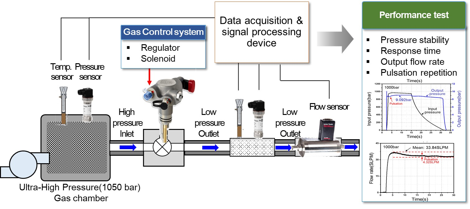
3. Performance Test and Evaluation

Shown in Figure 2, comprehensive test equipment has been developed for measuring the various performances of solenoid valves such as the response time according to input pressure, temperature increases upon repetition, pulsation under operation, the output flow rate, etc. The regulator and solenoid valve characteristics are measured and evaluated from an embedded controller (NI 9039) for multiple data acquisition.

3.1. Regulator Characteristics

The input/output pressure, flow rate response and depressurization characteristics are measured as follows, and a schematic diagram of the regulator is shown in Figure 3. The depressurization is measured from the output pressure compared with an increasing input pressure from 700 to 1000 bar, increasing in increments of 100 bar, respectively. The results (input(output)) were 9.078(700), 9.085(800), 9.091(900) and 9.092(1000) bar, as shown in Figure 4 and satisfied the 1%±0.2% output ranges with no pressure pulsation.
Moreover, the output flow rate of the regulator was measured at 31.25 SLPM (700 bar), 32.72 SLPM (800 bar), 33.09 SLPM (900 bar) and 33.84 SLPM (1000 bar) with decreasing flow pulsation as shown in Figure 5. According to the results for the characteristics, the regulator maintains the pressure and flow rate for various input pressures with allowable pulsation. Furthermore, the demanded discharge flow of regulator has no loss of flow compared with the input flow rate and satisfied 2000–2200 SLPM with regard to the hydrogen flow rate and the cross-sectional areas of the valve. In order to evaluate the pulsation characteristics of the smart valve, the pulsation range has to be measured according to the opening valve pressure variation. The pulsation increase appears as the input pressure of the solenoid valve is increased. Nevertheless, the pulsation decreases after passing through the regulator.

3.2. Solenoid Valve Characteristics

The solenoid valve dynamic characteristics evaluation was performed with the valve opening voltage with various input pressure conditions. The main plunger must be operated in harsh conditions in terms of applying the voltage to the solenoid coil, and determining whether the valve open or not, with an appropriate response time, is a prerequisite.
Therefore, evaluating the dynamic characteristics of the smart valve was carried out by varying various parameters such as the applied voltage, amount of current in the coil, temperature, pressure of the input/output, flow rate of the gas and pulsation of the valve. Moreover, the test equipment consisted of a DC power supply; a current, pressure and temperature sensor; and a flow meter. The accelerometer attached at the solenoid valve for measuring the vibration since the operation of the valve and the specification of the test equipment with a controller (NI 9039) is shown in Table 1.
The primary parameters for performance evaluation, including the applied voltages for operating the plunger under valve opening conditions, are listed in Table 2. The operating gas used nitrogen instead of hydrogen due to the safety matters concerns regarding explosion.
In order to verifying the response characteristics of the smart valve, the opening time according to the input pressure and applied voltage was measured. Generally, the time constant τ is the time dimension, which indicates the time elapsed upon reaching 63.2% of the steady state. Nevertheless, in this research, two times the time constant τ, which shows 86% of the steady state pressure, would be regarded as the fully open valve time, as shown in Figure 6.
Table 3 shows the results of the opening test, increasing the pressure and applying the voltages of 7 to 12 V. The temperature was 25 °C in every test, and the results show that the valve does not work with an input voltage of 7 V up to 800 bar pressure. Therefore, the minimum input voltage is 8 V for operating under ultra-high pressure. Moreover, the fully open response time was measured as 1 s on average, with a minimum of 0.91 s at 12 V and maximum of 1.45 s at 8 V. When the applied voltage was 8 V, a time delay occurred due to insufficient pressure at 1000 bar, and the response time was shortened by increasing the pressure. The response time of the solenoid valve is shown in Figure 7. The valve fully opened appropriately in the voltage range of stable vehicle driving, 9–12 V. Moreover, the valve reaction time increased at less than 8 V.

3.3. Evaluation of PulsationCharacteristics

The pulsation range increases as the output pressure increases from 700 to 1000 bar and as the pulsation increases from 3.21 to 6.53 bar. Nevertheless, pulsation decreased after passing through the regulator, as shown in Figure 8. The output pressure and flow rate are stable up to the maximum pressure.
Moreover, to measure the output vibration of the regulator, an accelerometer was attached as shown in Figure 2. The vibration after opening the solenoid valve measured 8.87 g and was 10.23 g at the beginning of the regulator under normal operating conditions at the maximum pressure of 1000 bar. Furthermore, the vibration was constant at 1.31 g, and the input pressure and output flow rate were at a steady state as shown in Figure 9. In the case of the unstable state, which is when the solenoid valve has not been fully opened, 1.27 g vibration occurred and the vibration was lower than at steady state due to depressurization from the solenoid valve (Figure 10). The test result for vibration under high pressure conditions is fairly good when compared with the results for commercial valves.

3.4. EnduranceEvaluation

The principle of the operating regulator is the balance between the diaphragm and the spring to open the channel. Therefore, the constant of the spring is a significant parameter for regulator performance. To evaluate the spring’s durability, test apparatus was designed. The spring durability test was performed with five thousand cycles with 400 N forces. The spring constant decreased from 62.516 to 60.348 N/mm. The endurance test for the smart valve, which was designed in this research, was performed and evaluated. Durability tests were done according to repetition time at the valve opening voltage under ultra-high pressure. The allowable valve open voltages of 8 and 9 V were applied and maintained for 10 minutes for measuring the opening time to determine the decrease in the intensity of the magnetic field under continuous operation due to the temperature increasing in the solenoid coil. In case of the input voltage being 8 V, a delay appeared, at the opening valve maximum, of 14.03 s, due to insufficient force to transport the plunger.
Nevertheless, when applying 9 V to the solenoid, 0.97 s of delay occurred over 30 minutes of operation time at 50.1 °C, as shown in Figure 11. Therefore, the minimum voltage to apply to the solenoid valve could be determined as 9 V for normal operation. Moreover, increases in temperature according to operating time were negligible, as the results show temperatures for the solenoid lower than the maximum allowable [10].

4. Conclusions

In this paper, an ultra-high pressure test bed has been developed for a hydrogen charging and transportation system with an integrated solenoid valve and regulator operating with precision control. Performance was tested and evaluated under various conditions such as various applied voltages, ranges of input pressure, operation times, output flow rates, amounts of pulsation, and repetition test for ensuring the safety, including considering the increases in temperature, the response time, the minimum voltage to be applied, etc. The results of the experiments show good potential for application in fuel charging and transporting commercial hydrogen vehicles. Moreover, comprehensive test equipment for the solenoid valve for ultra-high pressure hydrogen gas has been designed and described. The next stage of this research will be a field test, attaching the system in an actual vehicle for improving performance and efficiency.

Author Contributions

R.-W.K. performed formal analysis and investigation; K.-H.H. performed data curation, visualization; S.-R.K. built up the research project and performed project administration, J.-H.L. contributed to the supervision and wrote the paper. All authors have read and agreed to the published version of the manuscript.

Funding

This work was supported by Changshin University Research Fund of 2020-045.

Conflicts of Interest

The authors declare no conflict of interest.

References

  1. Nicoleti, G. The hydrogen option for energy: A review of technical, environmental and economic aspects. Int. J. Hydrog. Energy 1995, 20, 759–765. [Google Scholar] [CrossRef]
  2. Hua, T.Q.; Ahluwalia, R.; Peng, J.K.; Cromer, M.; Lasher, S.; Kenney, K.M. Technical assessment of compressed hydrogen storage tank systems for automotive applications. Int. J. Hydrog. Energy 2011, 36, 3037–3049. [Google Scholar] [CrossRef] [Green Version]
  3. Jinyang, Z.; Xianxin, L.; Ping, X.; Pengfei, L.; Yongzhi, Z.; Jian, Y. Development of high pressure gaseous hydrogen storage technologies. Int. J. Hydrog. Energy 2011, 37, 1048–1057. [Google Scholar]
  4. Son, D.-S.; Hong, J.-H.; Chang, S.-H. Determination of the autofrettage pressure and estimation of material failures of a Type III hydrogen pressure vessel by using finite element analysis. Int. J. Hydrog. Energy 2012, 37, 12771–12781. [Google Scholar] [CrossRef]
  5. Qian, J.Y.; Wu, J.-Y.; Gao, A.-X.; Wu, A.; Jin, Z.-J. Hydrogen decompression analysis by multi-stage Tesla valves for hydrogen fuel cell. Int. J. Hydrog. Energy 2019, 44, 13666–13674. [Google Scholar] [CrossRef]
  6. Klebanoff, L.E.; Pratt, J.W.; LaFleur, C.B. Comparison of the safety-related physical and combustion properties of liquid hydrogen and liquid natural gas in the context of the SF-BREEZE high-speed fuel-cell ferry. Int. J. Hydrog. Energy 2017, 42, 759–774. [Google Scholar] [CrossRef] [Green Version]
  7. Yanchao, L.; Mingshu, B.; Bei, L.; Yonghao, Z.; Wei, G. Effects of hydrogen and initial pressure on flame characteristics and explosion pressure of methane/hydrogen fuels. Fuel 2018, 233, 269–282. [Google Scholar]
  8. Chen, F.-Q.; Zhang, M.; Qian, J.-Y.; Chen, L.-L.; Jin, Z.-J. Pressure analysis on two-step high pressure reducing system for hydrogen fuel cell electric vehicle. Int. J. Hydrog. Energy 2017, 42, 11541–11552. [Google Scholar] [CrossRef]
  9. Ahmadi, P.; Kjeang, E. Realistic simulation of fuel economy and life cycle metrics for hydrogen fuel cell vehicles. Int. J. Energy Res. 2017, 41, 714–727. [Google Scholar] [CrossRef]
  10. Angadi, S.V.; Jackson, R.L.; Choe, S.Y.; Flowers, G.T.; Suhling, J.C.; Chang, Y.K.; Ham, J.K.; Bae, J.I. Reliability and life study of hydraulic solenoid valve. Part 2: Experimental study. Eng. Fail. Anal. 2009, 16, 944–963. [Google Scholar] [CrossRef]
Figure 1. Schematic diagram of the solenoid valve.
Energies 13 02446 g001
Figure 2. Comprehensive test equipment for a smart valve for ultra-high pressure hydrogen gas.
Energies 13 02446 g002
Figure 3. Schematic diagram of the regulator.
Energies 13 02446 g003
Figure 4. Comparison of the input and output pressure of the regulator.
Energies 13 02446 g004
Figure 5. Comparison of the input and output flow rates of the regulator.
Energies 13 02446 g005
Figure 6. Valve responses until steady state.
Energies 13 02446 g006
Figure 7. The results for the response time according to the pressure.
Energies 13 02446 g007
Figure 8. The output pressure according to pulsation.
Energies 13 02446 g008
Figure 9. The vibration characteristics under normal conditions.
Energies 13 02446 g009
Figure 10. The vibration characteristics in solenoid valves that are not fully opened.
Energies 13 02446 g010
Figure 11. Repetition test results.
Energies 13 02446 g011
Table 1. Specification of the test equipment with controller.
SensorSpecification
PressureMeasuring range: 0–1600 bar, 0–60 bar
Accuracy: ±0.5%
Response: 1 ms
TemperatureMeasuring range: 0–400 °C
CurrentMeasuring range: 50 mA–100 A
AccelerometerMeasuring range: 10, 50 g
Accuracy: ±5%
FlowMeasuring range: 0–3000 SLPM
Accuracy: ±1%
GAS(Leak)Measuring range: 0–1000 ppm
Embedded controller (NI 9039)Embedded controller
1.91 GHz processor
16 GB nonvolatile storage
Table 2. The valve opening conditions.
ParameterConditions
Input voltage (V)7, 8, 9, 10, 11, 12
Input pressure (bar)700, 800, 900, 1000
GasNitrogen
Sampling rate100 Hz
Table 3. The results for the response time.
Input PressureApplied Voltage (V)
7 V8 V9 V10 V11V12 V
700 bar1.031.031.031.011.000.97
800 barX1.030.990.980.980.96
900 barX0.990.970.970.970.93
1000 barX1.450.960.960.910.91

