Article

Analysis and Design of Innovative Magnetic Wedges for High Efficiency Permanent Magnet Synchronous Machines †

1
Department of Electrical, Computer and Biomedical Engineering, University of Pavia, Via Ferrata 5, 27100 Pavia, Italy
2
Department of Engineering Enzo Ferrari, University of Modena and Reggio Emilia, Via P. Vivarelli 10, 41125 Modena, Italy
*
Author to whom correspondence should be addressed.
This paper is an extended version of our paper published in the 2019 21st European Conference on Power Electronics and Applications (EPE ′19 ECCE Europe), Genova, Italy, 3–5 September 2019.
Energies 2020, 13(1), 255; https://doi.org/10.3390/en13010255
Submission received: 16 November 2019 / Revised: 28 December 2019 / Accepted: 2 January 2020 / Published: 4 January 2020

Abstract

:
The global decarbonization targets require increasingly higher levels of efficiency from the designers of electrical machines. In this context, the opportunity to employ magnetic or semi-magnetic wedges in surface-mounted permanent magnet machines with fractional-slot concentrated winding has been evaluated in this paper, with the aim to reduce the power losses, especially in the magnets. Since an analytical calculation is not sufficient for this evaluation, finite element methods with two different software have been employed, by using a model experimentally validated on a real motor. The effects of wedges with different values of permeability and different magnetization characteristics have been evaluated on flux density, back electromotive force, and inductances, in order to choose the more suitable wedge for the considered motor. Furthermore, a new wedge consisting of different portions of materials with different magnetic permeability values is proposed. The effects of both conventional and unconventional magnetic wedges were assessed to optimize the motor performance in all working conditions.

1. Introduction

Permanent magnet synchronous machines (PMSMs) with fractional-slot concentrated winding (FSCW) provide numerous benefits with respect to machines with traditional distributed winding [1]. The main advantages are related to the possibility of attaining many poles with a relatively small number of slots, and hence with a compact radial dimension of the machine; additionally, the slot fill factor is higher (up to 60%) and the end windings are shortened, with consequent savings in conductive material and reduced axial dimension.
From a performance point of view, compared to similar motors with distributed winding, in most cases, PMSMs with FSCW present:
  • Greater efficiency, essentially due to the reduction of Joule losses (at the expense of an increase in iron and magnet losses);
  • Greater power density, thanks to the reduced size of the machine;
  • Higher field weakening capability;
  • Fault tolerance.
Considering the overall system, consisting of the PMSM and its load or prime mover, the FSCW permits a direct coupling to be achieved, when the required speed at a rated frequency is low, so a gearbox would be unnecessary and therefore the efficiency of the entire system would be increased, reducing also its size, weight, noise, maintenance costs, and failure rate.
From the manufacturing point of view, this design allows for easier and faster insertion of the coils into the slots, which, generally, have to be open, with the following drawbacks:
  • Increase in the Carter factor and the equivalent length of the airgap, with a consequently greater reluctance of the magnetic path;
  • Worsening of the harmonic content of the magnetic field, with particular negative consequences in surface-mounted permanent magnet (SPM) machines;
  • Possible increasing in the cogging torque, due to the considerable discontinuity of the magnetic permeability of the stator core.
In order to mitigate the problems mentioned above deriving from the design of the stator slot opening, it is possible to use magnetic or semi-magnetic wedges, with the effect of simulating semi-closed slots. In the literature, different solutions have been proposed for this purpose for different types of electrical machines, but very few papers have focused on radial PMSMs and in particular on high torque and low speed SPM machines, as in this research.

1.1. State of the Art of the FSCW Machines

FCSW has been considered in the last 15 years as a valid alternative for PMSMs with respect to the traditional distributed winding. Many researches are present in the literature, mainly related to three-phase radial-flux machines [1,2,3,4,5], but also on axial-flux [6], tubular and flux-switching machines, and to machines with more than three phases [7]. Nevertheless, in this paper, the analysis of FCSW has been limited to the most widespread application, i.e., three-phase radial-flux machines. The first most significant researches on this topic are reported in [1,2,3,4,5], but more recently, other interesting papers have been published and the conclusions of some of them are reported in the following.
One of the drawbacks arising from FCSW is the increase in the rotor losses, due to the large amount of magnetomotive force harmonics produced by this type of winding. In [8], the effects of multilayer windings on rotor losses, especially the eddy-current losses in the permanent magnets of IPM machines with FSCW, were studied by means of the 2-D finite element analysis.
Another winding method is presented in [9] to eliminate both the sub and super space harmonics of the FCSWs in which the stator slot numbers are integer multiples of six. The proposed method is based on three concentrated single-layer windings in which the number of turns in one layer is optimized while the other layers are moved to cancel the subharmonics. The application of the proposed winding concept to a PMSM demonstrates the cancellation of dominant sub and super harmonics, reduction of the total harmonic distortion (THD), reduction of torque ripple, and minimization of core loss.
In [10], a multi-layer winding was designed to achieve an innovative symmetrical FSCW with unconventional slot–pole combinations. A general design methodology for this purpose is presented and validated by finite element analysis. The application of an unconventional FSCW to a shipboard surface permanent-magnet machine prototype is presented to illustrate the possible practicality of this type of winding; tests on the prototype for experimental validation are reported.
In [11], a method is proposed to reduce the torque pulsation of the three-phase FSCW interior permanent magnet (IPM) motors by lowering the subharmonics. The key principle of this method is the selection of an optimized six-layer winding with a different number of conductors. The optimized six-layer winding is used to suppress the first subharmonic and ensure that the second subharmonic is zero in a novel 9-slot/8-pole IPM motor.
Based on the consideration that the increase in the number of pole pairs leads to a lower electromagnetic yoke, and therefore to lower vibration and magnetic noise, in [12], the influence of different numbers of pole pairs on the vibroacoustic design aspects of the machine was studied, considering the natural frequencies under a variable speed analysis. The paper aimed to determine the optimal number of pole pairs for a low-speed and high-torque PMSM with FSCWs for wind turbine applications. Both 3-D finite element analysis and experimental investigations were used.
From this analysis, it is clear that in the last years that the research in this field has been focused in particular on the design of special windings to solve the drawbacks arising from FCSWs; however, this choice could impose many constraints for the design of the machine and involve manufacturing complications and higher costs for its realization.

1.2. State of the Art of the Magnetic Wedges Employed in Rotating Electrical Machines

The first researches on the use of magnetic wedges date back to at least 50 years ago and mainly concern the application to induction motors. The problem starts from the consideration that high-power rotating electrical machines, with the stator winding connected to the voltage in the order of a few kilovolts, require the manufacture of form-wound coils, which are made and insulated separately, and then inserted into the stator slots, which must be open. However, the open slots have some drawbacks, which are derived from the variations in the airgap permeance produced by the relatively wide opening of the slots. These drawbacks include the high frequency no-load losses, higher magnetizing current due to the increase in the effective airgap, consequent reduction in efficiency, and the power factor. The influence of the stator slot opening is stronger in induction motors, which have a higher “slot-opening/airgap” ratio than synchronous machines [13]. This is related to the fact that induction machines require a smaller airgap with respect to synchronous ones, due to the need to contain the value of the magnetizing current. Even if this requirement is valid, especially for large machines, the first studies have been applied to small ones.
A first investigation on a 3.7 kW motor showed that the use of magnetic wedges in induction motors can improve their performance, especially at full load [13]. However, the paper does not answer questions related to the mechanical strength and durability of the wedges under service conditions in large machines. A second study proved that soft ferrite magnetic wedges in a 0.75 kW induction motor decrease the 17th and 19th asynchronous torques (this effect is equivalent to the rotor skewing), but they are not able to reduce the 5th asynchronous and synchronous torques [14].
A more recent paper, focused on both induction and synchronous motors, starts from the assumption that it is possible to obtain a high power density in rotating electrical machines by increasing the flux density at the airgap, and in particular by shortening the length of the airgap [15]. Since this solution increases the ripple flux density of the tooth and, consequently, the losses on the surface of the poles, magnetic wedges have been proposed to reduce these losses. Magnetic wedges with a relative permeability, µr, from 10 to 30 were evaluated and the calculated and measured results on large motors (500 and 745 kW) indicated the effectiveness of the magnetic wedges, selecting µr = 10 as the most suitable.
In [16], the effects of magnetic wedges with µr = 8 and different dimensions were evaluated in the stator slot ripple components of the airgap flux density distribution and in the rotor current of a 55 kW squirrel cage induction motor. The simulated and experimental results showed a reduction of these components but also revealed that a thicker magnetic wedge can induce an increase of the slot leakage flux and a decrease of the power factor.
The impact of magnetic wedges in high power induction motors has also been studied in recent years. An interesting study is reported in [17], where the effects of two commercial magnetic wedges were simulated by finite element (FE) analysis and experimentally tested on a squirrel cage induction motor of 1660 kW, 6.6 kV. Both wedges have a relative permeability of few units, based on the value of the magnetic flux density. The authors prove that magnetic wedges offer the following advantages: (i) Reduction of the magnetizing current (less no-load current); (ii) consequent reduction of the Joule losses in the stator winding and increase of the efficiency of the machine; and (iii) in the case of totally enclosed fan cooled (TEFC) motors, a further benefit is the reduction in temperature rise. However, a qualification process is needed to ensure a reliable magnetic wedge system, as the flux density increases with greater permeability and the forces acting on the magnetic wedges also increase.
In [18], the influence of semi-magnetic wedges with µr = 10 on the harmonic content of the magnetic field at the airgap and on the electromagnetic characteristics of a 4 kW induction motor was studied through FE analysis. The results indicate that these wedges lead to a decrease in the airgap magnetic field space harmonic content. In addition, the electromagnetic torque is characterized by significantly lower oscillations, resulting in a longer bearing lifecycle. This behavior leads to an improvement of the motor efficiency but also to a lower power factor at the rated speed. The performances of a 2.2 kW induction motor with magnetic wedges of different permeability were evaluated in [19] by FE analysis. The authors concluded that this solution improves the motor performance, even if it tends to decrease drastically when µr > 20, as most of the flux lines is shorted in the wedges. Another recent paper reports a study on a 120 kW, 350 V induction motor with a squirrel cage rotor [20]. The FE analysis and the experimental tests showed that the magnetic wedges with µr = 4 significantly reduced the load current (thanks to a reduction of the magnetizing current) and increased both the power factor and the efficiency. However, when the relative permeability of the magnetic wedges was greater than 30, the torque of the motor decreased and, consequently, both the motor efficiency and the power factor tended to decrease due to the leakage fluxes. The optimal value of the magnetic wedge relative permeability, corresponding to the maximum efficiency of the motor, can be found for each case by using FE analysis. The use of magnetic wedges has also been evaluated in a special type of induction machine, i.e., a 250 kW brushless doubly fed machine, which can be employed for offshore wind power generation. The results show that magnetic wedges increase the series inductance in the equivalent circuit, which significantly affects the reactive power control and the rating of the converter [21]. A very recent paper explored the impact of adopting semi-magnetic wedges in wound field synchronous machines and concludes that they can be useful for reducing the pole face losses, the stator air-gap Carter coefficient, and, as a consequence, the rotor DC current required for the rated flux together with the associated loss and temperature rise [22].
Over the past 20 years, some papers have addressed axial flux permanent magnet machines (AFPMs) with slotted winding, which are suitable for electric traction applications, such as wheel motors. The slotted winding allows a slight flux weakening capability, but it generates a significant cogging torque and a large harmonic content in the back electromotive force (e.m.f.), due to the magnetic anisotropy of the stator. The use of magnetic wedges, with a relative permeability in the range between 10 and 100, causes an increase in the phase inductance, as well as a good reduction of the cogging torque. In [23], a 2D FE procedure, validated with experimental tests, was applied to a three-phase machine, with a single central stator and two rotors, one slot per pole and per phase, with a nominal power of 8 kW. Magnetic wedges significantly increase the phase inductance while the mutual inductance is nearly not affected. As a drawback, this solution increases the axial force between the stator and rotor by about 20% in comparison to standard non-magnetic wedges. A similar machine was simulated in [24,25], by means of 2D and 3D FE models, considering magnetic wedges of different heights and with a variable gap in the center of the wedge. The performances of this machine were analyzed both at no-load and at load, highlighting the advantages and disadvantages offered by the various solutions.
A new magnetic wedge design was rated for an AFPM in [26,27,28]. It was obtained from a normal magnetic wedge by milling a straight hollow groove along the length of the wedge. The groove was filled with a non-magnetic bar, which had a purely mechanical function of increasing the strength of the wedge. The main influences of this magnetic wedge design can be observed in terms of the cogging torque and stator phase slot leakage inductance. These two effects determine the most convenient cross-section design of the wedge, depending on the specific application. The large inductance allows to advantageously reduce the flux-weakening current and helps to reduce the short-circuit current, which is very important, especially in permanent magnet machines, to avoid demagnetization in the case of failure.
The influence of magnetic wedges on a 110 kW radial flux interior permanent magnet (IPM) motor with concentrated winding was investigated in [29], using flux 2D analysis and experimental tests. The machine was designed for traction applications, with a torque demand in the low speed area up to 2.5 times the nominal torque, and in the high speed area, a good field weakening capability. Several wedge materials were evaluated, with a relative permeability of 1, 1.5, 3, 30, 300, and 500. The authors showed that magnetic wedges reduce iron losses and, above all, permanent magnet losses, around the rated speed. However, magnetic wedges with a relative permeability greater than 3 do not provide an advantage but rather a disadvantage, since they significantly reduce the maximum torque.
Recently, magnetic wedges were considered for applications to switched reluctance machines, which has two important drawbacks: Torque ripple and stator vibrations. Using FE simulations, the authors demonstrated that, although the introduction of magnetic wedges degrades the average torque, it does reduce the radial force and torque ripples [30].
For a better understanding, two illustrations of wedges for FSCW machines are reported in Figure 1: Note that these wedges are non-magnetic, but the shapes of magnetic wedges are the same and also the method to assemble them in the stator slots.

1.3. Novelties of the Paper

In this paper, first of all, the main issues in the design of FSCW-SPM machines will be investigated, with particular attention to the effect of this type of winding on the losses of the machine. After that, a preliminary study on the effects of magnetic wedges in SPM machines will be carried out, in order to choose the best compromise for the value of magnetic permeability of these wedges. Finally, a case study will be introduced and the most suitable characteristics of the wedges for this case will be studied, in terms of material, geometry, and their combinations, through finite element (FE) simulations, with the aim of optimizing motor performance. Particular attention will be paid to the reduction of power losses in the magnets. Different configurations of the magnetic wedge will be evaluated, not only for the specific application but also to evaluate the effects derived from this type of wedge on machines with other characteristics, in order to obtain a broader estimate of the benefits and critical problems deriving from this change in the stator design.
The main differences and contributions of this paper compared to the literature are given by: (i) The proposal to use magnetic wedges to solve the problems provided by FSCW for SPM machines with radial flux for applications with high torque and low speed; and (ii) the evaluation of an innovative unconventional magnetic wedge that allows optimization of the overall performance of this type of machine.

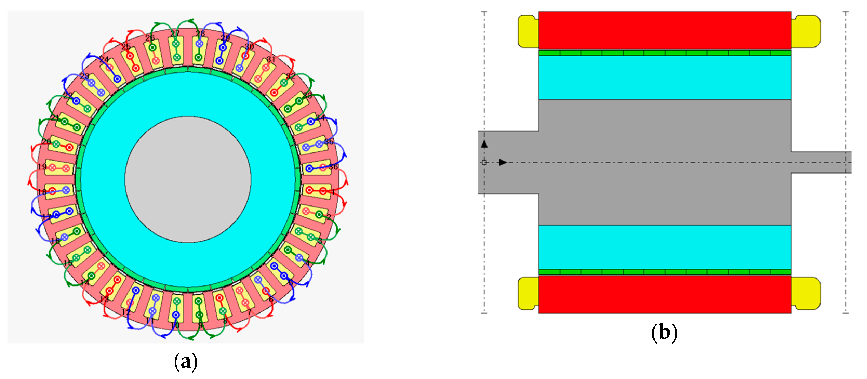
2. Design of a FSCW-SPM Synchronous Machine

As explained in the introduction, the FSCW can provide advantages to PMSMs, but its design has to take into account several requirements to be optimized for the specific application. Multiple combinations are possible to obtain a FSCW, but only some are convenient in order to have:
  • High winding factor for the fundamental component of the magnetomotive force (m.m.f.), which maximizes the torque;
  • Low winding factor for the other harmonics of the m.m.f., which reduces the torque ripple;
  • Reduced cogging torque;
  • Null unbalance in the electromagnetic force.
The first requirement is related to the maximization of the torque, but it may be in contrast with the second one, which, on the other hand, is related to the reduction of the losses in the rotor iron and magnets, due to the presence of harmonics in the m.m.f. It has been demonstrated in [2,3] that a high winding factor for the fundamental component (kw1 ≥ 0.866) needs a q number of slots per pole and per phase comprises between 0.25 and 0.5:
0.25 ≤ q = Q/(3 · p) ≤ 0.5,
where Q is the total number of stator slots, p is the number of poles, and 3 is the number of phases. A good choice may be, for example, p = 10, Q = 12, and q = 2/5, which determines kw1 = 0.933. The same value of kw1 is obtained when Q = 36 and p = 30, because the q number is equal [2]. These two choices allow a cogging torque to also be obtained with a short period, which is, as a consequence, negligible.
In general, the period, τ, of the cogging torque is given by the following formula:
τ = 360°/LCM (Q, p),
where LCM is the least common multiple. This formula provides a low value when the p number of poles and the Q number of slots are similar, as in the case of a FSCW, contrary to a distributed winding. In Figure 2, a comparison between the cogging torque for two small machines (1.4 kW) with the same number of slots and different number of poles is reported. The simulations are realized by Motor-CAD software, by maintaining the same dimensions of the machine. It is possible to observe that the peak value of the cogging torque is reduced by 75% in the case of a higher number of poles, even with a relatively small number of slots.
Considering again the winding factor, an important difference is given by the single- or double-layer winding. In the same conditions of the number of slots and poles, a single-layer winding presents a winding factor of the fundamental higher than a double-layer winding, which implies a higher value of constant torque but also a higher value of the total harmonic distortion (THD) of the m.m.f.; moreover, the harmonic content of the flux density and the back electromotive force (BEMF) is also higher. As a consequence, a single-layer winding produces a higher torque ripple and higher losses in the magnets and iron. For this reason, normally, the double layer is preferred (see an example in Table 1).
It is important to remember that a FSCW determines not only the harmonics multiple of the fundamental, as in the case of distributed winding, but also sub-harmonics, which can have a noticeable amplitude, sometimes even higher than the fundamental, especially in the case of single layer. Note also that more than two layers can be realized, even if with a more complex structure.
The fourth requirement, i.e., a null unbalance in the electromagnetic force, can be achieved by the presence of a “symmetry” in the winding. For example, by considering two double-layer windings, the first one with Q = 9 and p = 10, and the second one with Q = 36 and p = 40, we can observe that the latter presents a lower torque ripple and a null unbalance in the electromagnetic force, contrarily to the first one. In Figure 3, the flux density distribution at no-load for the same machine with two different windings is shown. Note that the range of the flux density is comprised between almost zero (blue color) and 1.7 T (red color).
Since the machine with 9 slots and 10 poles does not present any symmetry in the flux density distribution, a resultant unbalance force is generated, despite no eccentricity being present (see Figure 4). In general, this unbalance appears when p = Q ± 1 [3].

3. Power Losses in FSCW SPM Synchronous Machines

3.1. Joule Losses

Stator Joule losses cover most parts of the power losses in a PMSM supplied at low frequency (less or equal to the industrial frequency). At the same conditions of current density, J, these losses increase with the total volume of the conductor material. From this point of view, FSCW gives two advantages: On the one hand, the slot fill factor can reach values until 60%, much higher than a traditional distributed winding. In this way, the section of the conductor can be larger and therefore the current can be higher, by maintaining the same value of J, thus obtaining higher power at parity of dimensions or a more compact machine for the same power. On the other hand, an FSCW presents shorter end-windings with respect to a distributed winding, with consequent lower Joule losses. This effect becomes particularly relevant in machines with an active length that is relatively short with respect to the diameter at the airgap, as in the case of machines with a large number of poles. The best solutions is given by a two-layer winding, with a vertical division in the slot, which allows the minimum end-winding volume to be obtained with respect to a single or a double layer with horizontal separation [4].

3.2. Iron Losses

Stator iron losses can be reduced with standard methods employed for all types of AC electrical machines, e.g., by using steel sheets with low specific iron loss, especially in the case of machines supplied at high frequency.
Rotor iron losses are only due to the harmonics of a rotating magnetic field, and for this reason, they are much lower than stator iron losses. In particular, sub-harmonics due to the FSCW, not present in the case of distributed winding, cause the main part of these losses. In [5], it was demonstrated that these losses are higher in the case of single layer with respect to double or quadruple layer. These two latter windings present very similar rotor iron losses, which, in general, increase with the rotor speed. Moreover, [5] puts in evidence that the flux generated by the permanent magnets (PMs) mitigate the effect of the harmonics produced by the FSCW.

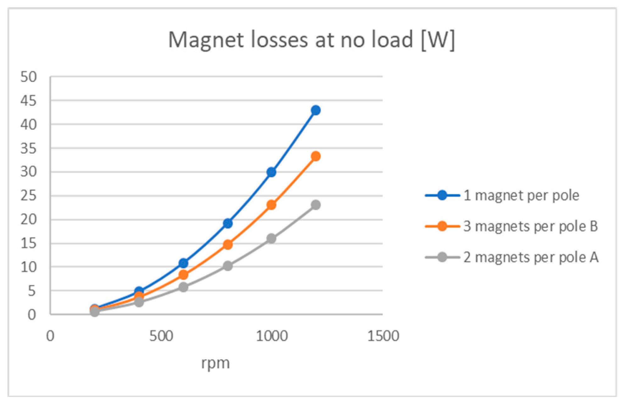
3.3. Losses in the Magnets

Losses in the magnets, which can be named also as “magnet losses”, are mainly due to the eddy currents arousing from the rotating magnetic field and therefore they will be higher in the case of FSCW, especially with a single layer, with respect to distributed winding. Beside the issue due to this additional component in the losses, there is the problem given by the overheating of the magnets, which increases the possibility of demagnetization. This phenomenon has to be absolutely avoided, because it can greatly compromise the operation and the performance of the machine. The methods that can be applied to reduce these losses comprise the segmentation of the magnets, axially or along the circumference; the higher the segmentation, the lower the eddy currents. This benefit is more relevant in the case of segmentation parallel to the axis of the rotor, as in Figure 5a, even if it leads to greater manufacturing difficulties. On the contrary, a segmentation parallel to the circumference of the rotor, as in Figure 5b, becomes necessary in the case of a large power machine with a long rotor, due to the problem of assembling long magnets. In Figure 6, the results of a simulation with Motor-CAD are shown, highlighting the increase of magnet losses with the square of the rotor speed, for three different configurations of magnets.
Nevertheless, in general, segmentation can cause problems of mechanical strength, due to the repulsive forces among the magnets composing the same pole, because of their same polarity and short gap between them; the repulsive forces depend on the materials magnetic properties and are proportional to H2, where H is the magnetic field strength (A/m).
Another solution to reduce the magnet losses consists in the use of magnetic wedges, instead of the traditional non-magnetic ones, to close the stator slots, which, in the case of FSCW, are generally open and therefore worsen the harmonic content of the flux density at the airgap. In the following paragraph, the state of the art related to the use of this type of wedge is presented.

4. Application of Magnetic Wedges in SPM Synchronous Machines

Based on the literature review reported in the introduction, the authors decided to study the possible benefits of using magnetic wedges in a different type of machine, such as an SPM motor with FSCW, with particular attention to low speed and high torque applications. The contents of this section do not aim to optimize the design of the magnetic wedges but to examine the effects of these wedges, with different values of magnetic permeability, on the behavior and performances of this kind of machine, with particular reference to the flux distribution, BEMF, and inductances.

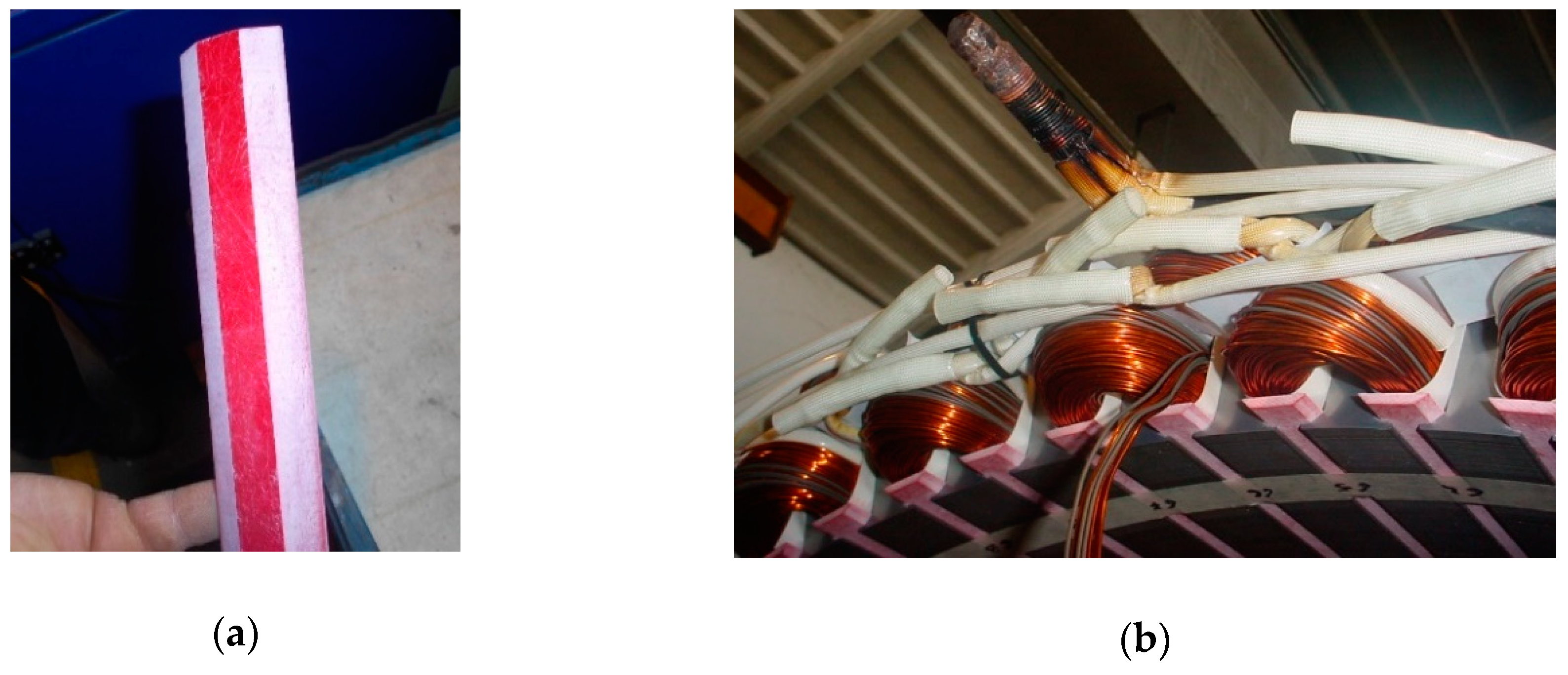
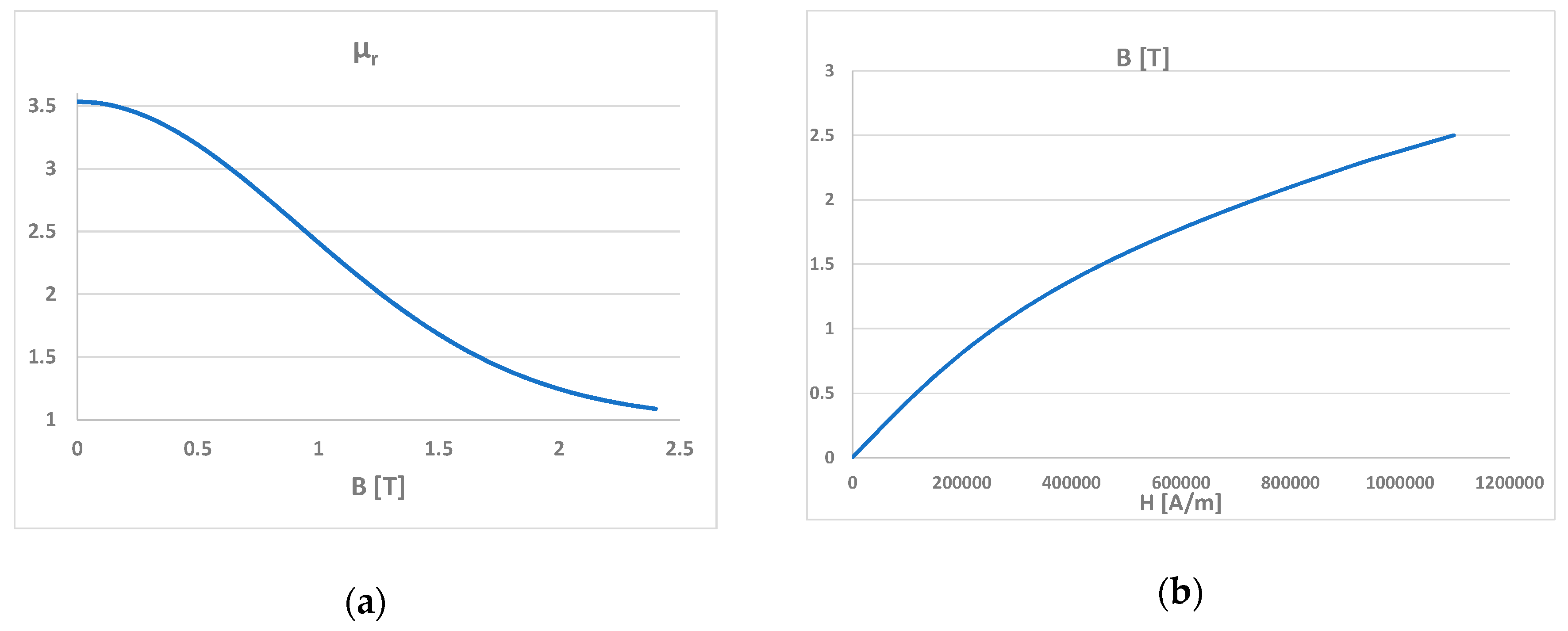
4.1. Characteristics of Magnetic Wedges

Typically, a magnetic wedge is composed by 70% iron powder, 20% epoxy resin, and 10% glass material, and its relative permeability is higher than one [17]. For each machine, an optimal value of relative permeability may be found to maximize its performance. Usually, this value is in the order of the magnitude of some units. This kind of wedge is defined as semi-magnetic (μr < 10). Wedges with μr > 10, even until some hundreds, are known as soft magnetic composite [29]. The exact composition of the magnetic wedges is often covered by trade secrecy; however, it is possible to assume that a different concentration of the ferromagnetic powder corresponds to a different relative permeability.
In the design phase of an electrical machine, an analytical calculation is not sufficient to evaluate the effects of precise values of the relative permeability and thickness of a magnetic wedge, but FE analysis is necessary. As a first approximation, the relative permeability can be assumed as constant, in order to identify its optimal value for the specific application; then, the wedge with the most suitable characteristics may be chosen, taking into account that its relative permeability tends to decrease beyond a certain value of flux density, due to the saturation.

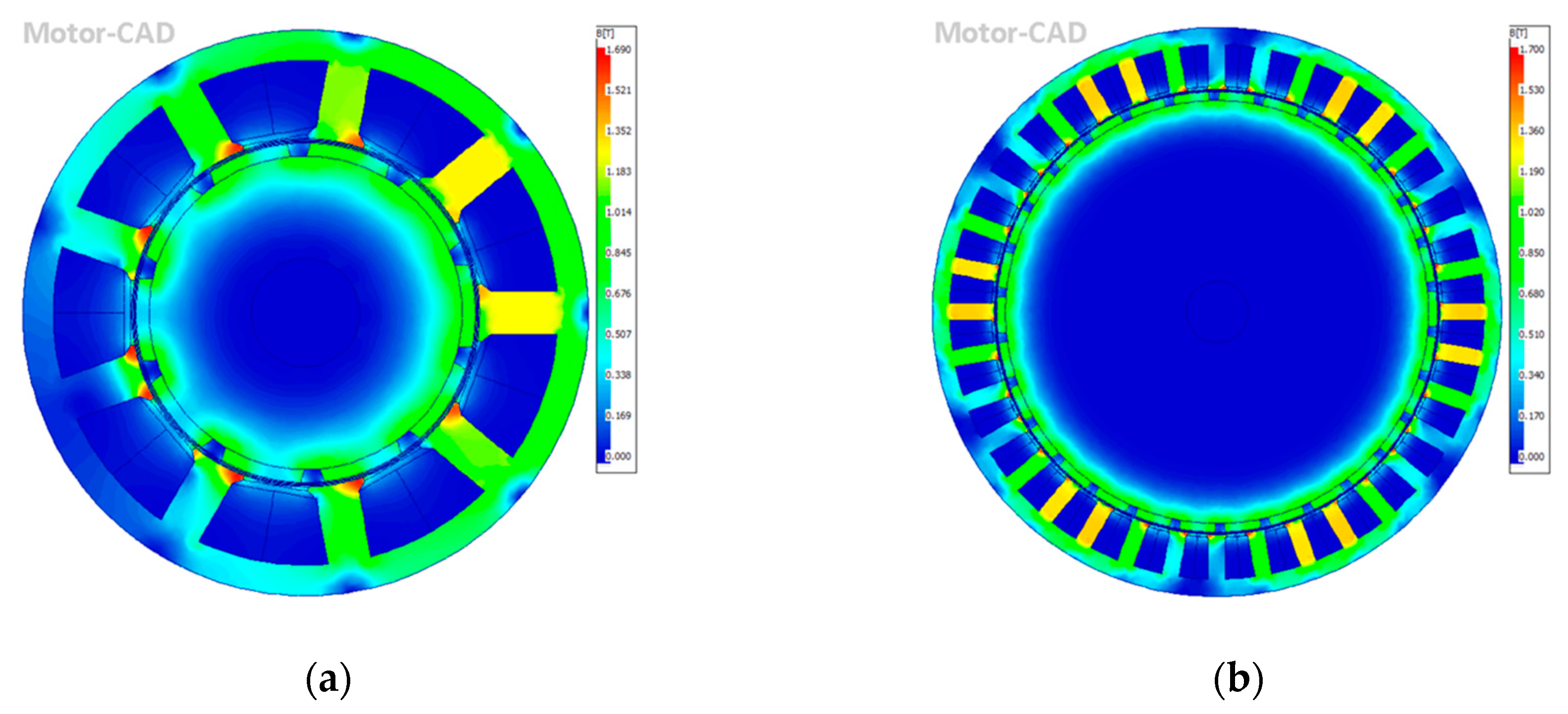
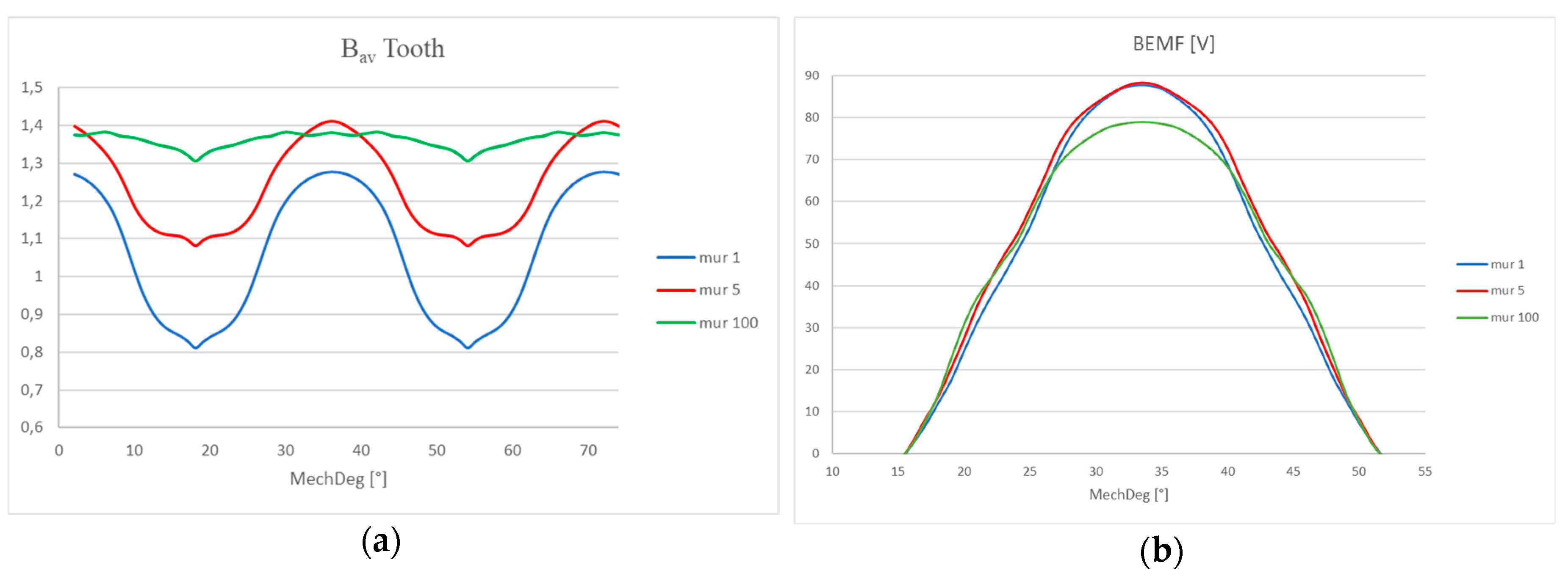
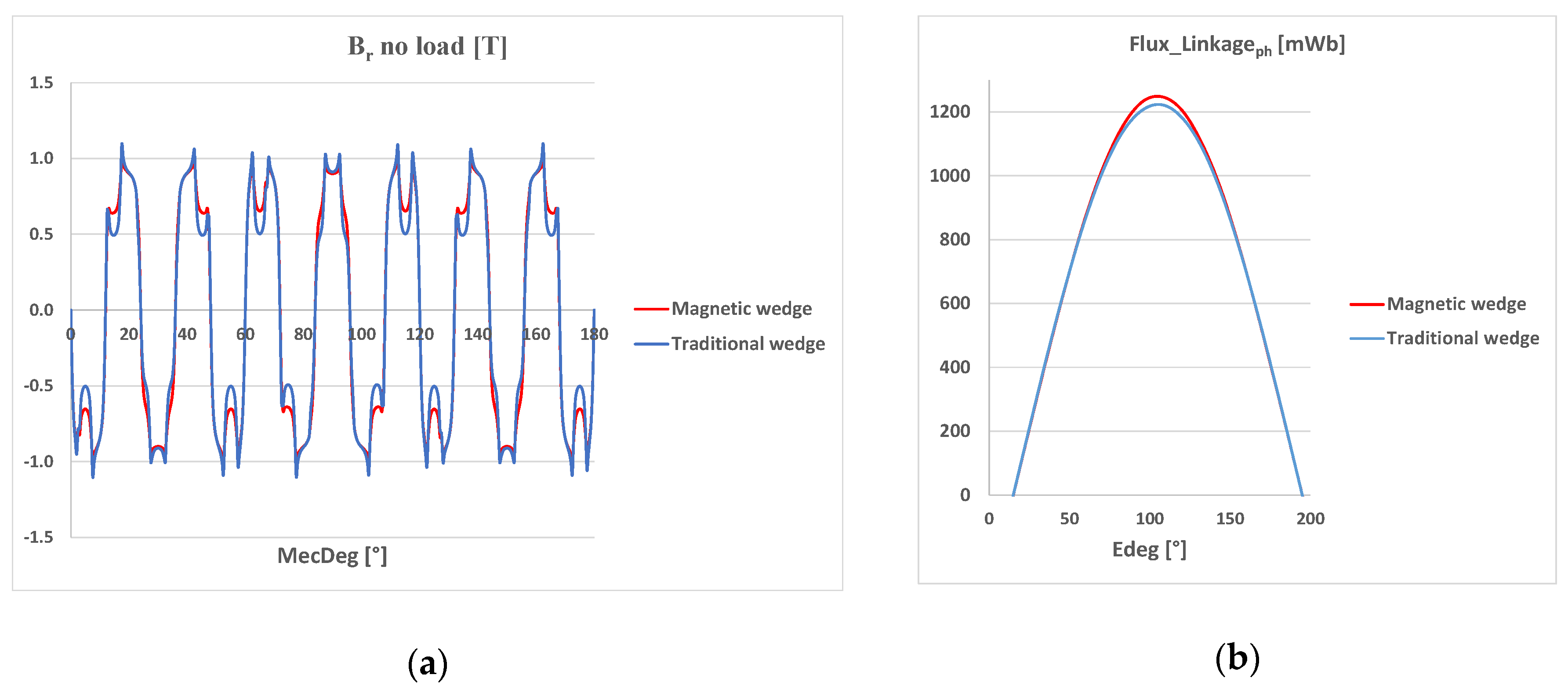
4.2. Effects of the Magnetic Wedges on the Flux Density and BEMF

In the following, some results from FE simulations are reported. They were carried out with Flux 2D and Motor-CAD (v11, Motor Design Ltd., UK) software related to an SPM motor with 12 slots, 10 poles, 130 mm external stator diameter, 80 mm internal stator diameter, 100 mm stator pack length, and rated power of 1.4 kW at 100 Hz. Figure 7a shows the average absolute value of the flux density under no load in a stator tooth with a thickness of 7.5 mm, as function of its relative position with respect to the rotor. As for the flux density at the airgap, its rms value is higher when a wedge with a larger permeability is used. However, after further increasing the relative permeability above 100, there are no longer any improvements in the trend of the flux density, which tends to saturate. In this case, the average flux density does not exceed 1.39 T for μr ≥ 100, so higher permeability wedges are useless. For this reason, only curves with μr until 100 are reported in Figure 7.
Apparently, wedges with μr = 100 seem to guarantee higher flux linkage and BEMF, due to the higher average flux density in the tooth. However, this higher average flux density in the tooth is due to the large values of the flux density reached in the polar shoe. From here, a part of the flux lines is deviated by the wedge with higher permeability, increasing the leakage flux. If the polar shoe is neglected, the average flux density in the top of the tooth is slightly higher with the wedge with μr = 5. This result confirms the higher BEMF obtained with μr = 5, as shown in Figure 7b.
In Figure 8, the flux density within the wedges is shown, in case of μr = 5 (a) and μr = 100 (b). As it can be observed, by increasing the relative permeability, the flux density increases, as the tendency to saturation. Note that the color scale in the two cases does not reflect exactly the same values of the flux density. For μr = 5 (a), the maximum value is 2.282 T, and for μr = 100 (b), it is 2.486 T. In Table 2, a short summary of the simulation findings obtained with FLUX 2D is reported. As a conclusion of this first investigation, we may state that it is possible to identify specific values of the relative permeability, according to the characteristics of the machine, which slightly increase the effective value of both the flux linkage, ψ, and BEMF. Moreover, these values allow a reduction of the harmonic content of the waveforms of these electromagnetic quantities. In general, it is difficult to optimize all the parameters of the machine, but it is possible to determine a valid compromise: In the considered case, μr = 5 or μr = 20.

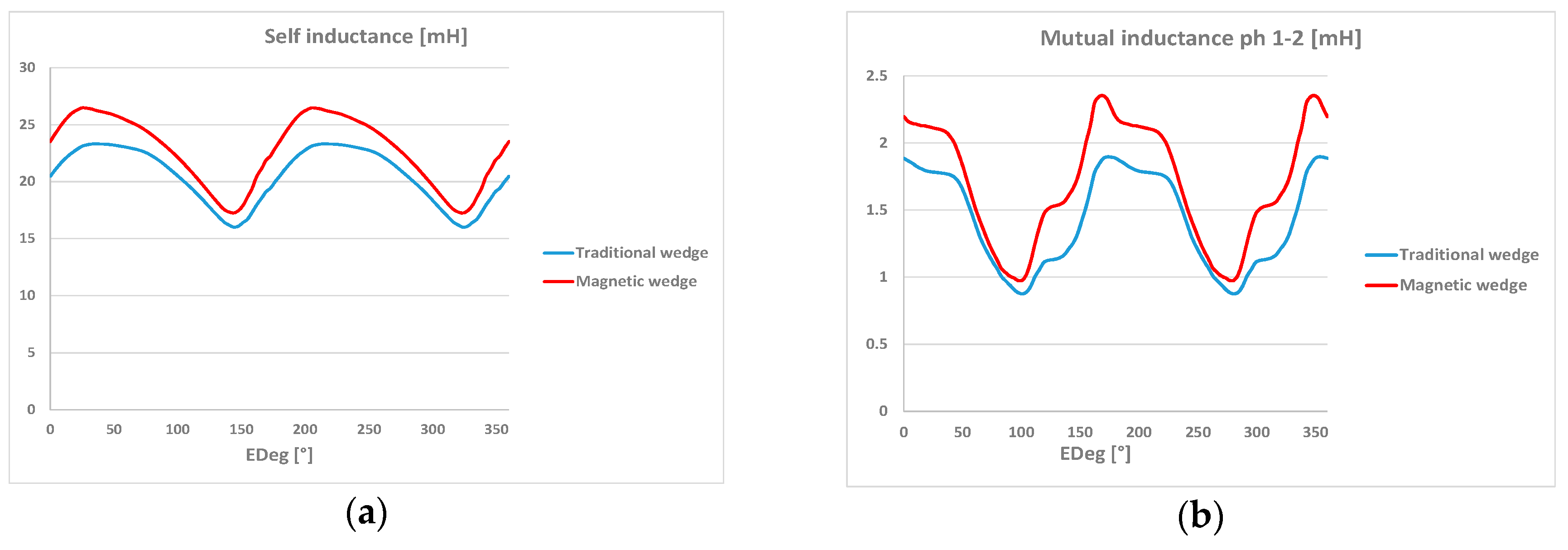
4.3. Effects of the Magnetic Wedges on the Inductances

The auto-inductance of a single phase, Lph. can be defined as:
Lph = La + Lσ,
where La is the magnetizing inductance, related to the flux linkage with the rotor, which crosses the airgap and produces the electromechanical conversion, while Lσ is the leakage inductance, related to the leakage flux, which has a path that does not pass through the airgap, but, for example, from a tooth to another one through a magnetic wedge. Providing the machine with paths with higher relative permeability can increase both La and Lσ, and so Lph.
In the conventional reference system used in this paper, the d axis is parallel to the flux coming from one pole of the machine and the id current can be used to regulate the effective flux linkage, defined as:
φ = φmLd id,
where φm is the flux linkage due to the magnets (which would be equal to φ in the rated condition) and Ld is the d axis inductance. In order to reduce φ, id has to be increased. With a higher Ld, the same flux linkage reduction can be obtained with a lower id, so a higher Ld allows a better flux weakening capability. The SPM machine is ideally isotropic, so the saliency (LqLd) is very small and nearly zero when saturation is low. The magnetic wedges also change the q axis inductance, Lq; however, only Ld is involved in the flux weakening capability. So, a little change in the saliency will not significantly affect the flux weakening capability, which, for this type of machine, is highly linked only to Ld. The torque formula adopted here is:
T = 3/4 p (φ − (LdLq) · Id) · Iq.
The simulations show an overall improvement in the auto-inductance, due to both greater values of leakage inductance, Lσ, and magnetizing inductance, La, the latter caused by a reduced reluctance of the magnetic circuit. The result is an increase in the inductance along the direct axis, Ld, which allows a better flux weakening capability to be obtained. Moreover, higher values of Ld give rise to lower short circuit currents.
By increasing the permeability of the wedges, the inductance increases and therefore even the voltage drops. Consequently, the maximum current that can flow in the stator windings decreases, taking into account the voltage limit imposed by the converter. The torque is directly proportional to iq. If a significant decrease in the maximum torque is not desired, wedges with a relative permeability of a few units should be used.

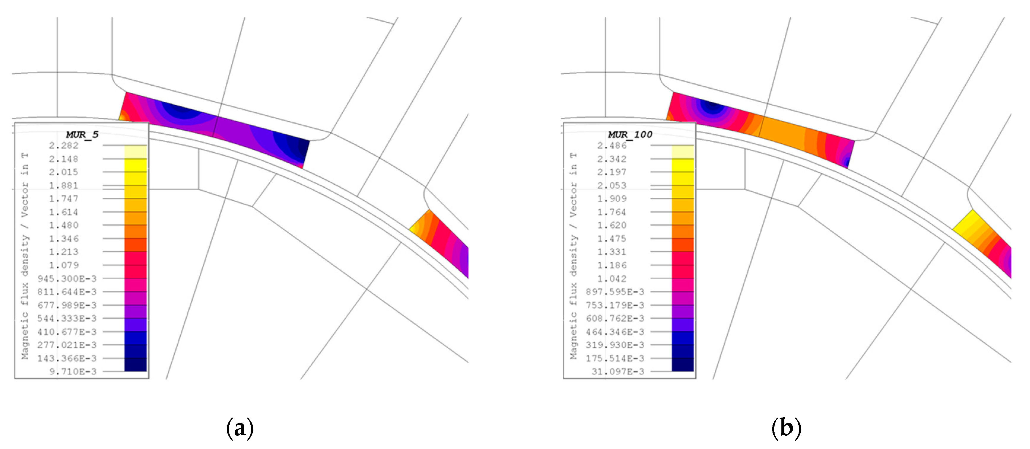
4.4. Effects of the Saturation on the Magnetic Wedges

The simulations carried out in this section have taken into account the saturation phenomenon on the magnetic wedge, even if it may tend to be established earlier, with lower values of flux density. A wedge with more pronounced saturation allows a lower improvement in the efficiency compared to another with less tendency to saturation. Moreover, the values of the inductance along the direct axis tend to be slightly lower, with consequently lower benefits in the weakening operation.
Regarding the power losses in the magnets, it can be proven that any phenomenon that tends to increase the saturation of the wedges has a negative impact on these losses. Wedges with a higher tendency to saturation are therefore more sensitive to load variations. Wedges with a high relative permeability reach saturation faster and consequently they are not very suitable for applications with rather high currents. In such cases, it is therefore preferable to use semi-magnetic wedges.
Therefore, on the basis of the results presented in this paragraph, for the case study, we chose to model magnetic wedges with a more marked saturation.

5. Case Study

The main motor data are shown in Table 3 and three images of it in Figure 9; other details are specified in [31]. The magnets are made of NdFeB and the stator is water cooled. The curves μrB and BH of the magnetic wedge were extrapolated from the technical sheet provided by a supplier and are reported in Figure 10. These magnetic wedges can be produced by sintering resin and iron powder.
The behavior of the motor with different types of wedges was simulated using two FE software, Motor-CAD and FLUX 2D (2018 version, Altair Engineering Inc., USA). Initially, Motor-CAD was used because the original motor, with standard non-magnetic wedges, was modelled with this software and validated by the company with experimental measurements. Therefore, it is reasonable that the simulations implemented with this model, varying the characteristics of the wedges, are reliable. In addition, this software takes little time to get results from simulations. However, some calculations require FLUX 2D, in particular for the spectrum analysis function, which provides the harmonics of any quantity, e.g., the airgap flux density. The distribution of the fractional-slot concentrated winding of the motor was calculated automatically with Motor-CAD, as shown in Figure 11a. The magnets are not segmented radially, but axially, as displayed in Figure 11b: Each pole comprises a series of 12 magnets, in order to reduce losses in the magnets due to eddy currents and to facilitate the assembly.

6. Behavior of SPM Synchronous Machines with Uniform Magnetic Wedges

The behavior of the machine with magnetic wedges, with the characteristics shown in Figure 10, was evaluated for different load percentages and compared with the same motor with conventional non-magnetic wedges.

6.1. Effect of Uniform Magnetic Wedges under No Load

Figure 12a shows the radial component of the airgap flux density under no load, both in the case of the traditional wedge and the magnetic wedge. It can be noted that the flux density is slightly less irregular in the case of a magnetic wedge and its rms value is greater than in the traditional wedge (Br = 0.762 T instead of Br = 0.738 T). The flux linkage also increases, as in Figure 12b, causing a slight increase of the rms value of BEMF (+1.34%) and the maximum value of the flux density in the tooth (from 1.726 to 1.759 T, increase of 1.88%.
The cogging torque period is 2° mechanical degrees and has not particularly high values, but the magnetic wedge permits to achieve a significant decrease, greater than 90%, even if its relative permeability is not too high, as in Figure 13a.
Without load, there is a net drop in magnet losses (−63%) and a growth in total iron losses (+7.4%); the latter is due to the fact that the rotor iron losses decrease, but their contribution is negligible compared to the stator iron losses, which increase, especially in the teeth, due to the increase in the flux density in this part of the machine. Note that the stator iron losses could further increase in the case of wedges with greater permeability. Overall, without load, total losses decrease slightly (−1.9%) and the performance of the machine is enhanced by the use of magnetic wedges, as the magnets are the most sensitive part of the machine and they are better protected with this solution. Nevertheless, to decide the convenience given by the use of magnetic wedges, it is also necessary to consider the behavior of the motor when loaded.

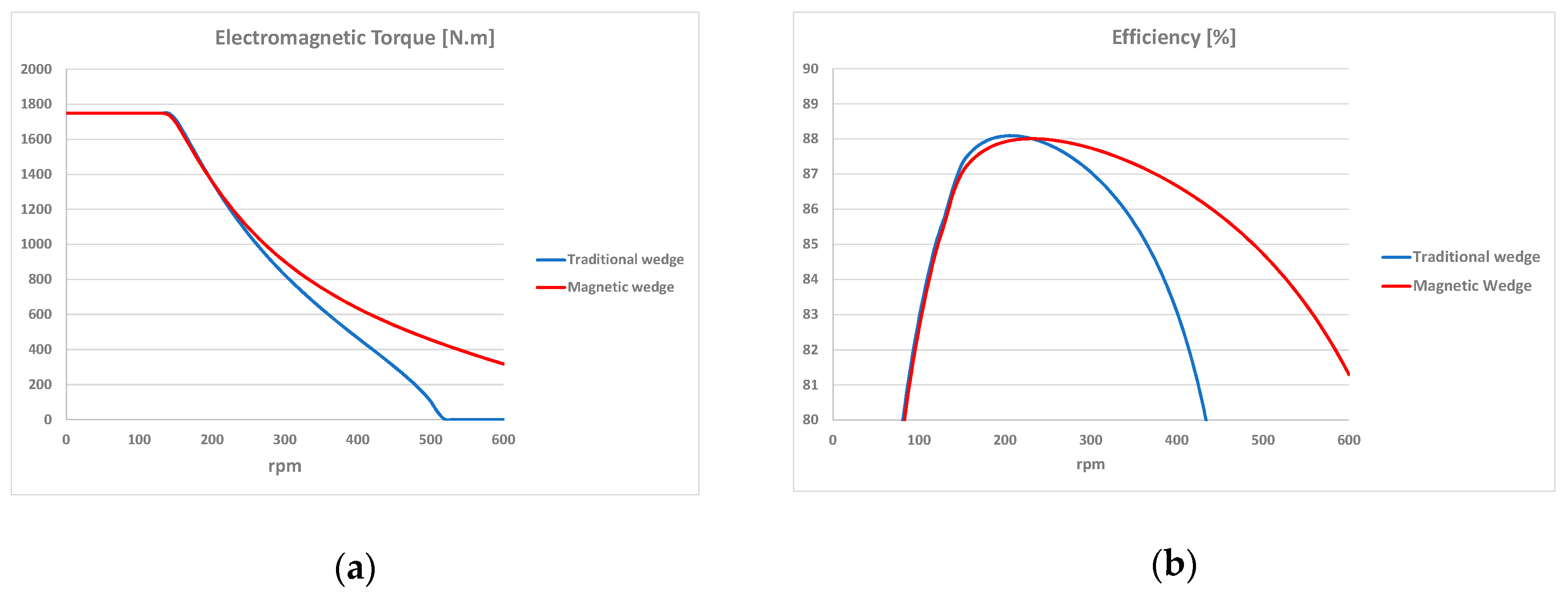
6.2. Effect of Uniform Magnetic Wedges at Full Load

In order to evaluate the effect of magnetic wedges on the behavior of the machine at full load, a comparison was made with traditional wedges on an equal value of the electromagnetic torque (1749 Nm), calculated by means of FE analysis with Motor-CAD, to correctly compare the losses. The average torque over an electrical period remains constant; however, in the two cases, there is a different ripple, as in Figure 13b. The magnetic wedge allows a slight reduction of 0.18%, from 1.89% to 1.71%. This result is obtained with a small increase of the line current (from 46.50 to 46.95 A), also due to a slight reduction of the power factor (from to 0.88 to 0.87).
At full load, the magnetic wedges provide an increase in self-inductance, due to the reduction in the reluctance of the magnetic circuit. Its average value rises by only 10.7%, both for the not very high permeability of the wedge and for the saturation present in some parts of the machine, as in Figure 14a. The mutual inductance also increases, by about 20%, as in Figure 14b, however, its absolute values remain low and do not cause any problem. Due to the saturation phenomena, the fully loaded machine behaves as not perfectly isotropic from the magnetic point of view. The inductance along the d axis increases as well and the flux linkage along the d axis decreases (Table 4).
As for the losses, since the current necessary to have the same torque is greater with the magnetic wedges, the Joule losses increase slightly (+1.9%). The rotor iron losses decrease, but the stator iron losses increase, and the total iron losses also increase. On the contrary, the losses in the magnets decrease (−29.4%), but the total losses slightly increase (+1.6%). Again, the magnets are better protected, but, overall, the use of magnetic wedges does not seem convenient at full load, especially considering that these wedges are more expensive and more prone to breaking than traditional ones. The reduced advantage at full load is given by the higher saturation induced by the higher currents, which decreases the positive effect of the magnetic wedges, which, in general, tend to accentuate the saturation locally.

6.3. Effect of Uniform Magnetic Wedges at Intermediate Load and in Field Weakening Operation

With intermediate load percentages, magnetic wedges offer greater advantages, since the losses are proportionally similar to those in the absence of load. The behavior of the machine was also assessed in field weakening area, for currents equal to the nominal one. As displayed in Figure 15a, at 500 rpm, the torque is zero with traditional wedges while with magnetic wedges, the machine is still able to provide a torque equal to 0.26 p.u. (456 N·m). This difference not negligible. Figure 15b underlines that, although at the rated speed the performance of the machine is better with the standard wedges, its behavior changes for a speed greater than 230 rpm. The magnetic wedges provide an efficiency greater than 80% even at 600 rpm while with traditional wedges, the efficiency drops below this threshold, starting from 440 rpm. It is clear that magnetic wedges offer greater flexibility in these working conditions.

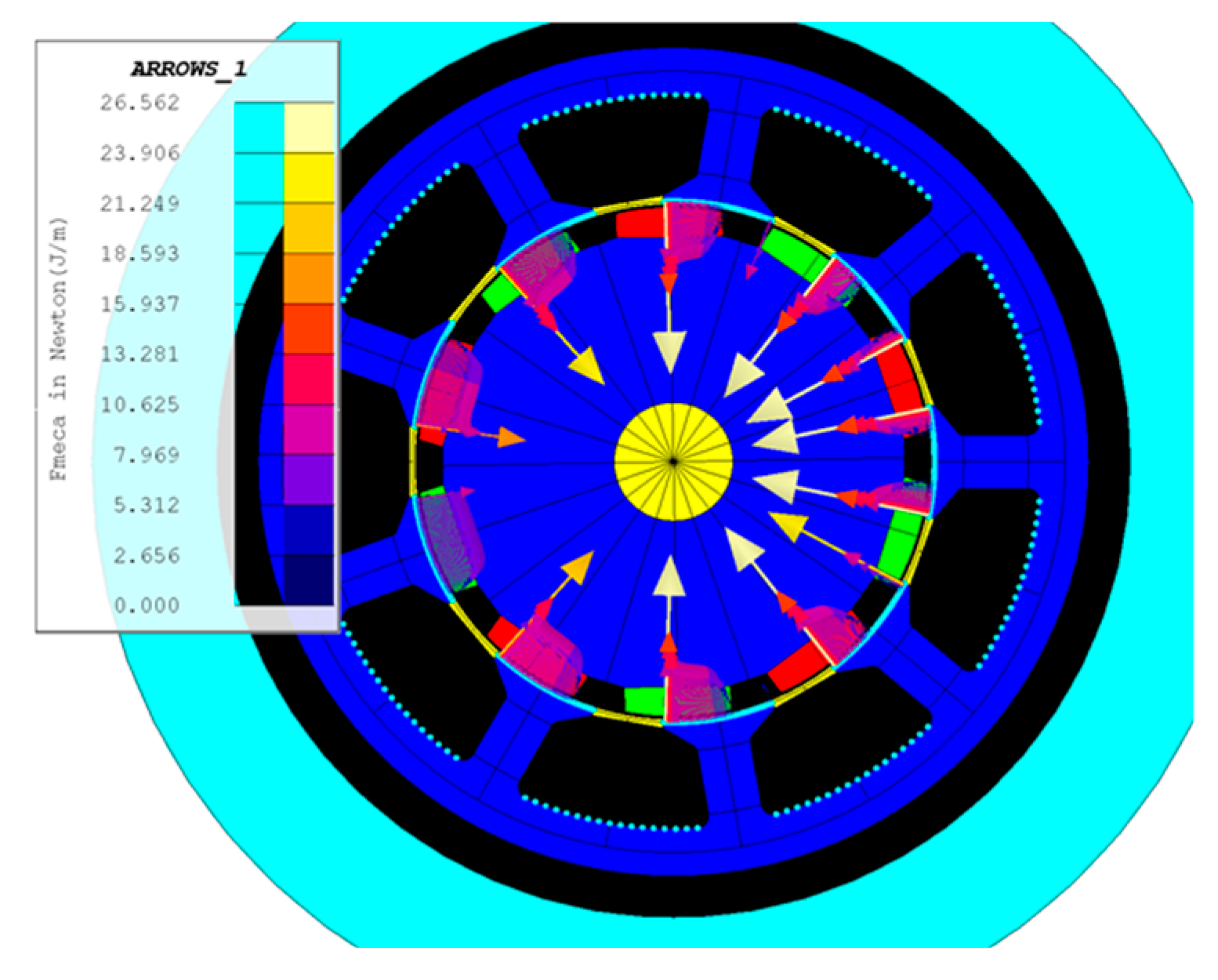
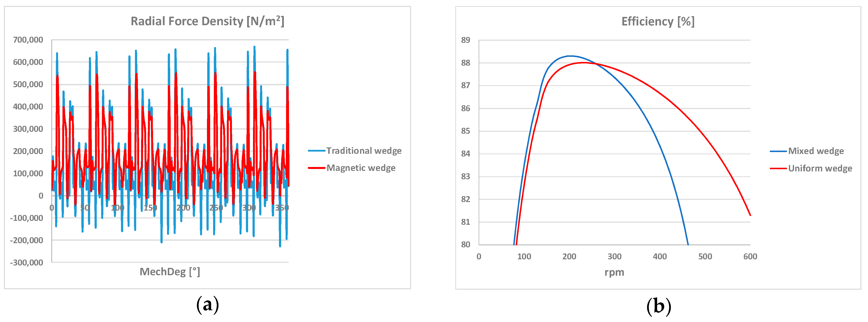
6.4. Effect of Uniform Magnetic Wedges on the Radial Forces

Finally, the radial forces acting on the internal stator surface were evaluated. The idea of this evaluation comes from the evidence that magnetic wedges are more brittle and hence more susceptible to failure compared to non-magnetic ones, as highlighted in [32]. An interesting analysis referring to a large synchronous wound field machine of 5 MW was reported in [33], where the results showed that the shape of the magnetic wedge also has significant effect on the stator interior surface force distribution.
From our analysis, with magnetic wedges, these forces are distributed more evenly and their maximum value decreases (−15.5%), while their average value is higher than the standard wedges (+26%). Therefore, the stress on the wedges increases with their permeability; nevertheless, the values achieved do not compromise their integrity, as shown in Figure 16a.

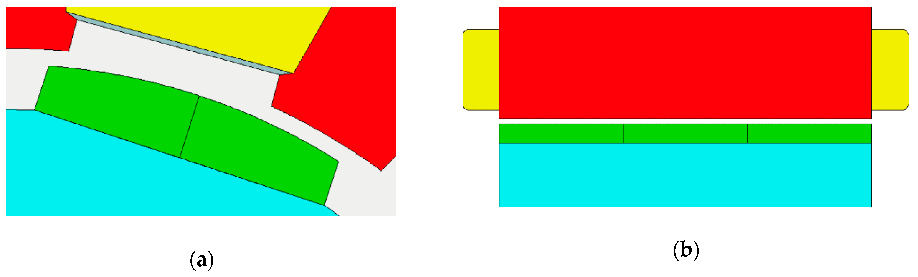
7. Optimization of a Non-Conventional Magnetic Wedge

The simulations reported in the previous paragraph permitted an estimation of the effects of commercial magnetic wedges with uniform permeability on the performance of an FSCW-SPM motor. It is clear that an increase in µr reduces the magnet losses but increases the leakage flux lines throughout the wedges. The consequence of these wedges is similar to that produced by a more or less accentuated closing of the slot. For this reason and on the basis of previous works in the literature [26,27,28], a different distribution of the relative permeability within the wedge was investigated, in order to imitate the behavior of a semi-closed slot and optimize the full load operation of the motor. The proposed wedge is divided in five portions of materials with three different values of µr: The central part with µr = 1, the ends with high permeability, and two intermediate portions with µr in the order of some units. In general, simulations have shown that an improvement in efficiency can be achieved with a permeability that increases from the center to the ends of the wedge. Many combinations of geometry and permeability were assessed, in particular by varying the length and permeability of the intermediate portions. The slot opening of the original motor is 10.8 mm wide and the best configuration found after many simulations has the following parameters: µr = 1 (central part), µr = 4 (intermediate parts), µr = 100 (ends). It was confirmed that values of µr > 100 in the ends of the wedge do not arouse any significant improvement in efficiency. It has to be noted that the configuration of this unconventional wedge differs from that proposed in [26,27,28], which has two zones with different permeability instead of three.

7.1. Effect of Non-Conventional Magnetic Wedges at Full Load

The comparison of the performance of the motor at full load, with a uniform and non-uniform (mixed) magnetic wedge, is reported in Table 5, together with the maximum values of the flux density in different parts of the machine. With the mixed wedge, the induction in the teeth is slightly higher (excluding the polar shoe). This also leads to a slight increase in iron losses, mainly located in the stator teeth.
The non-uniform magnetic wedge has a lower Ld than the uniform magnetic wedge, in particular it has a lower leakage inductance, Lσ, so lower voltage drops and higher flux linkage, while it produces similar magnet losses at full load. Therefore, it can provide the same torque with a lower current. By considering Figure 15b and Figure 16b, it is possible to note that the magnetic wedge with uniform magnetic permeability does not increase the efficiency for this machine at full load with respect to the traditional wedge (µr = 1), due to the high saturation. Conversely, the non-uniform magnetic wedge is able to do so. As illustrated in Table 5, the main advantage is given by the lower losses in the magnets.

7.2. Effect of Non-Conventional Magnetic Wedges in Field Weakening Operation

As for the field weakening operation, the trend with the mixed wedge is very similar to that achieved with a traditional wedge. The improvement over the latter is in fact minimal. Hence, if speeds above 2 p.u are desired, it is more convenient to use the uniform magnetic wedge, which consequently cannot be completely replaced by that with mixed permeability. The main reason is given by the different inductances in the two cases: The greater inductance due to the uniform wedge slightly worsens the power factor, but it permits a more flexible operation in terms of speed.
The efficiency reachable with mixed wedge, displayed in Figure 16b, is higher up to 260 rpm, i.e., up to a rotational speed of 2 p.u. Conversely, starting from 470 rpm, it drops below 80%. For applications up to 260 rpm, this solution is certainly more suitable, but it can also allow higher speeds to be reached, within the limits just mentioned.

7.3. Effect of Non-Conventional Magnetic Wedges at Low Load

The impact of this type of wedge is different for lower currents. In Table 6, it is possible to observe how the efficiency improvement tends to decrease and to become even slightly lower than the application with a traditional wedge, or a uniform magnetic one, with a load equal to one-quarter of the rated one.
The half load efficiency is still slightly higher, mainly thanks to the lower Joule losses. Hence, the main benefit of the mixed wedge lies in the reduction of the current necessary to supply the same electromagnetic torque; moreover, it guarantees greater protection of the magnets. Its use would therefore be particularly appropriate for nominal loads but also for half loads. On the contrary, it is counterproductive for low currents. Table 6 shows a summary of the losses. Joule losses are always lower with the mixed wedge, but when currents decrease, their impact on performance decreases, while that due to the losses in iron and magnets increases. The losses in iron are the highest with this type of wedge. For this reason, its use for low loads is not opportune.
By reducing the currents, their influence on the losses due to eddy currents induced in the magnets also decreases, then the wedge with a uniform relative permeability becomes better performing, although slightly.

8. Discussion

The aim of this research was to investigate the possibility to mitigate the main drawbacks given by the FSCW for SPM machines, with a more general manufacturing solution with respect to the methods based on the design of special windings, which impose many constraints in the project and realization of the machine. This solution is represented by the magnetic wedges, which have been considered in the literature for various types of rotating electrical machines, but not for SPM machines with radial flux, high torque, and low speed.
The investigation mainly considered the impact of wedges with various values of magnetic permeability and also a novel wedge composed of multiple materials with different magnetic permeability. Even the thickness and the shape of the wedge could be taken into account to find the best solution, but they are constrained by the shape and dimensions of the stator slots, which, on the other hand, are bound by the electromagnetic design of the machine. So, a study on the impact of the thickness and shape of the wedge would be limited to a specific machine, whereas the study on the impact of the relative permeability is more general. For these reasons, in this paper, the optimization of the wedge was mainly based on the distribution of the relative permeability.

9. Conclusions

The application of two different types of magnetic wedge in SPM synchronous motors with fractional-slot concentrated winding was studied in this paper, with the aim of overcoming the drawbacks deriving from this type of winding and improving the performance of this machine. Magnetic wedges were shown to reduce the harmonic content of the airgap flux density, with positive effects on magnet losses, and can achieve the same torque with lower currents, as well as a reduction in its ripple. Nevertheless, the degree of these improvements depends quite a lot on the type of load. The high currents also cause a greater saturation of the magnetic wedges with a resulting lower reduction of the losses in the magnets.
The uniform magnetic wedge is more appropriate in the case of field weakening operation and at low loads, where its saturation is limited, while the unconventional wedge lets a considerable decrease in the stator Joule losses, since the same torque is attained with a lower current, as well as a reduction in magnet losses. Conversely, this wedge does not seem to guarantee efficiency improvements at low loads.
In conclusion, the innovative magnetic wedge presented here combines the positive aspects of a traditional wedge with those of a uniform magnetic wedge, even if the absolute best magnetic wedge configuration cannot be defined, since the benefits depend on the specific application.

Author Contributions

Methodology, L.F. and M.P.; software, validation, formal analysis, investigation, M.P.; writing—original draft preparation, review and editing, supervision, L.F. All authors have read and agreed to the published version of the manuscript.

Funding

This research received no external funding.

Acknowledgments

The authors acknowledge: Gianpietro Pacinotti of COMER S.r.l., for his fundamental contribution related to experimental data and measurements for the validation of the model and for his proposal to investigate the effects due to the magnetic wedge on the performance of the machine; Alessandro Tassi of SPIN S.r.l. for the software technical support.

Conflicts of Interest

The authors declare no conflict of interest.

References

  1. EL-Refaie, A.M. Fractional-slot concentrated-windings synchronous permanent magnet machines: Opportunities and challenges. IEEE Trans. Ind. Electron. 2010, 57, 107–121. [Google Scholar] [CrossRef]
  2. Meyer, F. Permanent Magnet Synchronous Machines with Non-Overlapping Concentrated Windings for Low-Speed Direct-Drive Applications. Ph.D. Thesis, Royal Institute of Technology, Stockholm, Sweden, 2008. [Google Scholar]
  3. Martinez, D. Design of a Permanent-Magnet Synchronous Machine with Non-Overlapping Concentrated Windings for the Shell Eco Marathon Urban Prototype. Master’s Thesis, Royal Institute of Technology, Stockholm, Sweden, 2012. [Google Scholar]
  4. Salminen, P. Fractional Slot Permanent Magnet Synchronous Motors for Low Speed Applications. Ph.D. Thesis, Lappeenranta University of Technology, Lappeenranta, Finland, 2004. [Google Scholar]
  5. Alberti, L.; Bianchi, N. Theory and design of fractional-slot multilayer windings. IEEE Trans. Ind. Appl. 2013, 49, 841–849. [Google Scholar] [CrossRef]
  6. Chen, Q.; Liang, D.; Jia, S.; Ze, Q.; Liu, Y. Loss analysis and experiment of fractional-slot concentrated-winding axial flux PMSM for EV applications. In Proceedings of the 2018 IEEE ECCE, Portland, OR, USA, 23–27 September 2018. [Google Scholar]
  7. Abdel-Khalik, A.S.; Massoud, A.; Ahmed, S. Nine-phase six-terminal pole-amplitude modulated induction motor for electric vehicle applications. IET Electric Power Appl. 2019, 13, 1696–1707. [Google Scholar] [CrossRef] [Green Version]
  8. Sun, A.; Li, J.; Qu, R.; Li, D. Effect of multilayer windings on rotor losses of interior permanent magnet generator with fractional-slot concentrated-windings. IEEE Trans. Magn. 2014, 50. [Google Scholar] [CrossRef]
  9. Islam, M.S.; Kabir, M.A.; Mikail, R.; Husain, I. Method to minimize space harmonics of fractional slot concentrated windings in AC machines. In Proceedings of the 2018 IEEE ECCE, Portland, OR, USA, 23–27 September 2018. [Google Scholar]
  10. Tessarolo, A.; Ciriani, C.; Bortolozzi, M.; Mezzarobba, M.; Barbini, N. Investigation into multi-layer fractional-slot concentrated windings with unconventional slot-pole combinations. IEEE Trans. Energy Convers. 2019, 34, 1985–1996. [Google Scholar] [CrossRef]
  11. Liu, G.; Zhai, F.; Chen, Q.; Xu, G. Torque pulsation reduction in fractional-slot concentrated-windings IPM motors by lowering sub-harmonics. IEEE Trans. Energy Convers. 2019, 34, 2084–2095. [Google Scholar] [CrossRef]
  12. Asef, P.; Bargalló Perpiñà, R.; Lapthorn, A.C. Optimal pole number for magnetic noise reduction in variable-speed permanent magnet synchronous machines with fractional-slot concentrated windings. IEEE Trans Transport. Electrific. 2019, 5, 126–134. [Google Scholar] [CrossRef]
  13. Chalmers, B.J.; Richardson, J. Performance of some magnetic slot wedges in an open-slot induction motor. Proc. IEEE 1967, 114, 258–260. [Google Scholar] [CrossRef]
  14. Anazawa, Y.; Kaga, A.; Akagami, H.; Watabe, S.; Makino, M. Prevention of harmonic torques in squirrel cage induction motors by means of soft ferrite magnetic wedges. IEEE Trans. Magn. 1982, 18, 1550–1552. [Google Scholar] [CrossRef]
  15. Takeda, Y.; Yagisawa, T.; Suyama, A.; Yamamoto, M. Application of magnetic wedges to large motors. IEEE Trans. Magn. 1984, 20, 1780–1782. [Google Scholar] [CrossRef]
  16. Mikami, H.; Ide, K.; Arai, K.; Takahashi, M.; Kajiwara, K. Dynamic harmonic field analysis of a cage type induction motor when magnetic slot wedges are applied. IEEE Trans. Energy Convers. 1997, 12, 337–343. [Google Scholar] [CrossRef]
  17. Gaerke, T.R.; Hernandez, D.C. The temperature impact of magnetic wedges on TEFC induction motors. In Proceedings of the 2012 Annual IEEE Pulp and Paper Industry Technical Conference, Portland, OR, USA, 17–21 June 2012. [Google Scholar]
  18. Gyftakis, K.N.; Panagiotou, P.A.; Kappatou, J. The influence of semi-magnetic wedges on the electromagnetic variables and the harmonic content in induction motors. In Proceedings of the 2012 XXth ICEM, Marseille, France, 2–5 September 2012. [Google Scholar]
  19. Lavanya, M.; Selvakumar, P.; Vijayshankar, S.; Easwarlal, C. Performance analysis of three phase induction motor using different magnetic slot wedges. In Proceedings of the 2014 IEEE 2nd ICEES, Chennai, India, 7–9 January 2014. [Google Scholar]
  20. Madescu, G.; Moţ, M.; Greconici, M.; Biriescu, M.; Vesa, D. Performances analysis of an induction motor with stator slot magnetic wedges. In Proceedings of the 2016 International Conference on Applied and Theoretical Electricity, Craiova, Romania, 6–8 October 2016. [Google Scholar]
  21. Abdi, S.; Abdi, E.; McMahon, R. Numerical analysis of stator magnetic wedge effects on equivalent circuit parameters of brushless doubly fed machines. In Proceedings of the 2018 XIII ICEM, Alexandroupoli, Greece, 3–6 September 2018. [Google Scholar]
  22. Donaghy-Spargo, C.; Spargo, A. Use of fractional-conductor windings and semi-magnetic slot wedges in synchronous machines. J. Eng. 2019, 2019, 4396–4400. [Google Scholar] [CrossRef]
  23. Di Napoli, A.; Honorati, O.; Santini, E.; Solero, L. The use of soft magnetic materials for improving flux weakening capabilities of axial flux PM machines. In Proceedings of the 2000 IEEE Industry Applications Conference, Rome, Italy, 8–12 October 2000. [Google Scholar]
  24. De Donato, G.; Giulii Capponi, F.; Caricchi, F. Influence of magnetic wedges on the no-load performance of axial flux permanent magnet machines. In Proceedings of the 2010 IEEE International Symposium on Industrial Electronics, Bari, Italy, 4–7 July 2010. [Google Scholar]
  25. De Donato, G.; Giulii Capponi, F.; Caricchi, F. Influence of magnetic wedges on the load performance of axial flux permanent magnet machines. In Proceedings of the IECON 2010, Glendale, AZ, USA, 7–10 November 2010. [Google Scholar]
  26. Tessarolo, A.; Luise, F.; Bortolozzi, M.; Mezzarobba, M. A new magnetic wedge design for enhancing the performance of open-slot electric machines. In Proceedings of the 2012 Electrical Systems for Aircraft, Railway and Ship Propulsion, Bologna, Italy, 16–18 October 2012. [Google Scholar]
  27. Tessarolo, A.; Luise, F.; Mezzarobba, M.; Bortolozzi, M.; Branz, L. Special magnetic wedge design optimization with genetic algorithms for cogging torque reduction in permanent-magnet synchronous machines. In Proceedings of the 2012 Electrical Systems for Aircraft, Railway and Ship Propulsion, Bologna, Italy, 16–18 October 2012. [Google Scholar]
  28. Tessarolo, A.; Branz, L.; Mezzarobba, M. Optimization of a SPM machine using a non-isotropic magnetic wedge with an analytical method for cogging torque estimation. In Proceedings of the 2016 XXII ICEM, Lausanne, Switzerland, 4–7 September 2016. [Google Scholar]
  29. Lindh, P.M.; Pyrhönen, J.J.; Ponomarev, P.; Vinnikov, D. Influence of wedge material on losses of a traction motor with tooth-coil windings. In Proceedings of the IECON 2013, Vienna, Austria, 10–13 November 2013. [Google Scholar]
  30. Belhadi, M.; Krebs, G.; Marchand, C.; Hannoun, H.; Mininger, X. Evaluation of a switched reluctance motor with magnetic slot wedges. In Proceedings of the 2014 ICEM, Berlin, Germany, 2–5 September 2014. [Google Scholar]
  31. Frosini, L.; Pastura, M.; Pacinotti, G. Performance improvement of SPM synchronous machines with non-conventional stator slot magnetic wedges. In Proceedings of the EPE’19 ECCE Europe, Genova, Italy, 2–6 September 2019. [Google Scholar]
  32. Wang Lee, K.; Hong, J.; Hyun, D.; Bin Lee, S.; Wiedenbrug, E.J.; Teska, M.; Lim, C. Detection of stator-slot magnetic wedge failures for induction motors without disassembly. IEEE Trans. Ind. Appl. 2014, 50, 2410–2419. [Google Scholar]
  33. Chu, K.H.; Anand Prabhu, M.; Pou, J.; Ramakrishna, S.; Gupta, A.K. Analysis of local forces acting on stator teeth and magnetic wedges in large synchronous machines. In Proceedings of the 2018 ACEPT, Singapore, Singapore, 30 October–2 November 2018. [Google Scholar]
Figure 1. Typical wedges for FSCW machines: (a) a single wedge; (b) some wedges inserted in the stator slots.
Energies 13 00255 g001
Figure 2. Cogging torque for a 1.4 kW machine with: (a) Q = 12, p = 4, τ = 30°; (b) Q = 12, p = 10, τ = 6°.
Energies 13 00255 g002
Figure 3. Flux density distribution for a machine with: (a) Q = 9, p = 10; (b) Q = 36, p = 40.
Energies 13 00255 g003
Figure 4. Magnetic force distribution of the for a machine with Q = 9, p = 10.
Energies 13 00255 g004
Figure 5. Magnet segmentation: (a) Segmentation A, parallel to the axis (two magnets per pole); (b) Segmentation B, parallel to the circumference (three magnets per pole).
Energies 13 00255 g005
Figure 6. Magnet losses under no load for a 1.4 kW machine, Q = 12, p = 10 (simulation results).
Energies 13 00255 g006
Figure 7. FE simulation results under no load: (a) mean values of flux density in the tooth; (b) BEMF in one phase.
Energies 13 00255 g007
Figure 8. Flux density in the magnetic wedges under no load with: (a) μr = 5; (b) μr = 100.
Energies 13 00255 g008
Figure 9. SPM motor: (a) wound stator; (b) stator end-windings; (c) carbon fiber covered rotor.
Energies 13 00255 g009
Figure 10. Magnetic wedge characteristics: (a) relative permeability; (b) magnetization characteristics.
Energies 13 00255 g010
Figure 11. SPM motor: (a) fractional-slot concentrated winding; (b) axial section.
Energies 13 00255 g011
Figure 12. (a) Radial component of airgap flux density under no load; (b) Flux linkage with one phase.
Energies 13 00255 g012
Figure 13. (a) Cogging torque under no load; (b) Torque at full load.
Energies 13 00255 g013
Figure 14. (a) Self-inductance of phase 1 at full load; (b) Absolute value of mutual inductance between phase 1 and 2 at full load.
Energies 13 00255 g014
Figure 15. (a) Electromagnetic torque at variable speed; (b) Efficiency at variable speed.
Energies 13 00255 g015
Figure 16. (a) Radial component of the radial force density acting on the internal stator surface; (b) Electromagnetic torque at a variable speed.
Energies 13 00255 g016
Table 1. Comparison between the single and double layer for a 1.4 kW machine with Q = 12, p = 10.
THD BEMF [%]Tripple [%]kw1
Single layer9.1610.540.966
Double layer6.458.870.933
Table 2. BEMF (rms value, peak value, and THD) and leakage flux (rms value) of one phase, as a function of the magnetic permeability of the wedges.
μr = 1μr = 5μr = 20μr = 100Unit
BEMFrms57.896058.9355.87V
BEMFpeak87.7188.358478.85V
ψrms91959489mWb
THDBEMF9.666.644.133.78%
Table 3. Main data of the analyzed motor.
ParameterValueUnit of Measurement
Rated power23.1kW
Rated torque1700N·m
Rated speed130rpm
Rated frequency32.5Hz
Rated current46.5A
Rated voltage381V
Rated efficiency87%
Number of poles30-
Number of slots36-
Stator core length300mm
External stator diameter359mm
Internal stator diameter270mm
Shaft diameter150mm
Magnet length25mm
Magnet width6mm
Table 4. Mean values of inductances and flux linkage at full load.
ParameterTraditional WedgeMagnetic Wedge∆ (%)
Ld10.38 mH11.82 mH13.87
L20.65 mH22.86 mH10.7
|M|1.42 mH1.70 mH19.7
ψd1131 mWb1094 mWb−3.3
ψq785 mWb876 mWb11.6
Table 5. Power losses, efficiency, and flux densities of the motor at full load.
ParameterUniform WedgeMixed Wedge∆ (%)
PCu3512 W3286 W−6.4
Pmag56.62 W55.7 W−1.6
PFestat354.2 W361.1 W1.9
PFerot1.86 W1.87 W0.5
Ptot3924.68 W3704.67 W−5.6
Efficiency85.63%86.32%0.8%
Airgap flux density1.18 T1.13 T4.4%
Flux density in the tooth (no polar shoe)1.75 T1.77 T−1.1%
Flux density in the polar shoe of the tooth2.45 T2.43 T0.8%
Flux density in the stator yoke1.25 T1.23 T1.6%
Table 6. Efficiencies, Joule losses, iron losses, and magnets losses at low loads.
ParameterUniform WedgeMixed Wedge∆ (%)
Efficiency @ Pn/291.18%91.04%−0.2%
Efficiency @ Pn/491.77%92.02%0.3%
Stator Joule losses @ Pn/2855.2 W817.3 W−4.4
Stator Joule losses @ Pn/4212.5 W203.4 W−4.3
Total iron losses @ Pn/2296.55 W314.18 W5.9
Total iron losses @ Pn/4281.07 W304.52 W8.3
Magnets losses @ Pn/224.88 W25.15 W1.1
Magnets losses @ Pn/416.82 W17.44 W3.7

