1. Introduction
Energy crises all over the world have drawn serious attention to green energy. Many researchers have been paying attention to nanogenerators (NGs) for their wide applicability as well as studying how to harvest energy from the ambient environment to deal with energy related issues. A large amount of low grade waste heat is produced from various industrial processes and discharged into the atmosphere without being put into practical use. The United Nations reported in the 21st Conference of the Parties (COP21) that around 20% to 50% of the energy given to different industries is lost as waste heat. The opportunity to harvest this low grade thermal energy can open a new pathway and contribute to meet our energy needs.
At present, many researchers are showing interest in utilizing low grade waste heat for power generation. There are many low temperature differential (LTD) heat engines which can scavenge low grade thermal energy into electrical energy [
1,
2]. Haneman [
3] reported a research study based on LTD Stirling engines for energy scavenging. Some other types of magnetic engines have been reported to scavenge low grade thermal energy; however, these engines have some drawbacks and limitations and have not been found to be practical.
The discovery of gadolinium (Gd) [
4] was the breakthrough in the development of magnetic engines. Gd is used as a transition material in thermomagnetic engines. Thulium has the same properties as Gd and also can be used as a transition material in magnetic engines. However, Gd is preferred due to cost advantages and greater availability. Gadolinium acts like a ferromagnetic material below its Curie temperature of 20 °C, and is strongly attracted to a magnetic field. On the other hand, it shows paramagnetic behavior above this temperature. Gd causes a relative moment due to the distortion of flux lines in a magnetic field by heating and cooling it above and below the Curie point. When the hot stream of a jet impinges on a Gd block, it becomes paramagnetic while the cold stream of a jet makes it ferromagnetic. This change in the magnetic property of a Gd block interacts with a bar magnet and generates rotational mechanical energy.
In recent years, triboelectric nanogenerators (TENGs) [
5,
6,
7,
8] have been introduced, which can convert mechanical energy, such as wind power [
9], ocean waves [
10], and rain drops, into electrical energy based on the triboelectric effect and electrostatic induction [
11,
12]. TENG have advantages, such as light weight, low cost, and simple fabrication [
13,
14,
15]; however, there are some issues related to the output performance of TENG that need further improvement for long term operation. A TENG generates a high output voltage and a very low output current that limit its application to some extent. To overcome these issues, many researchers have hybridized it with other generators, like piezoelectric [
16], electromagnetic [
17], and thermoelectric generators.
In a previous work, Shaislamov et al. [
18] designed a TENG which can produce electricity from a rotating disk driven by an LTD heat engine. They were able to produce an effective output voltage of
Voc = 70 V and an output current of about
Isc = 0.31 μA from the non-contact sliding mode of the TENG. However, an important issue related to the reported TENG is the very low output current, which needs to be addressed. In the existing TENG, electricity is produced by only the triboelectric effect.
This work presents a hybrid (TENG-EMG) rotating disk type generator integrated with an LTD thermomagnetic engine for converting the rotational mechanical energy of a thermomagnetic engine into electrical energy. The main idea of the proposed work is how to generate energy at a low temperature difference between the heat source and the sink. Therefore, we introduced a novel design for a Gd-based thermomagnetic generator that can work in conjunction with the disk type (TENG-EMG) generator to scavenge low grade thermal energy into electrical energy.
The hybrid (TENG-EMG) generator has a better output performance than that of individual NGs (EMG or TENG). Operated at a rotational speed of 251 rpm, the TENG produces an average open circuit voltage of 9 V and a short circuit current of 0.9 μA while the electromagnetic generator (EMG) produces an average open circuit voltage of 2.3 V and a short circuit current of 1.5 mA under the same rotational speed. The output from both the TENG and EMG were combined for maximum efficiency. The presented thermomagnetic engine is an improved magnetic engine, which produces mechanical work by utilizing the properties of Gd and converts this mechanical energy into electrical energy by using the triboelectric and electromagnetic effect.
3. Working Principle
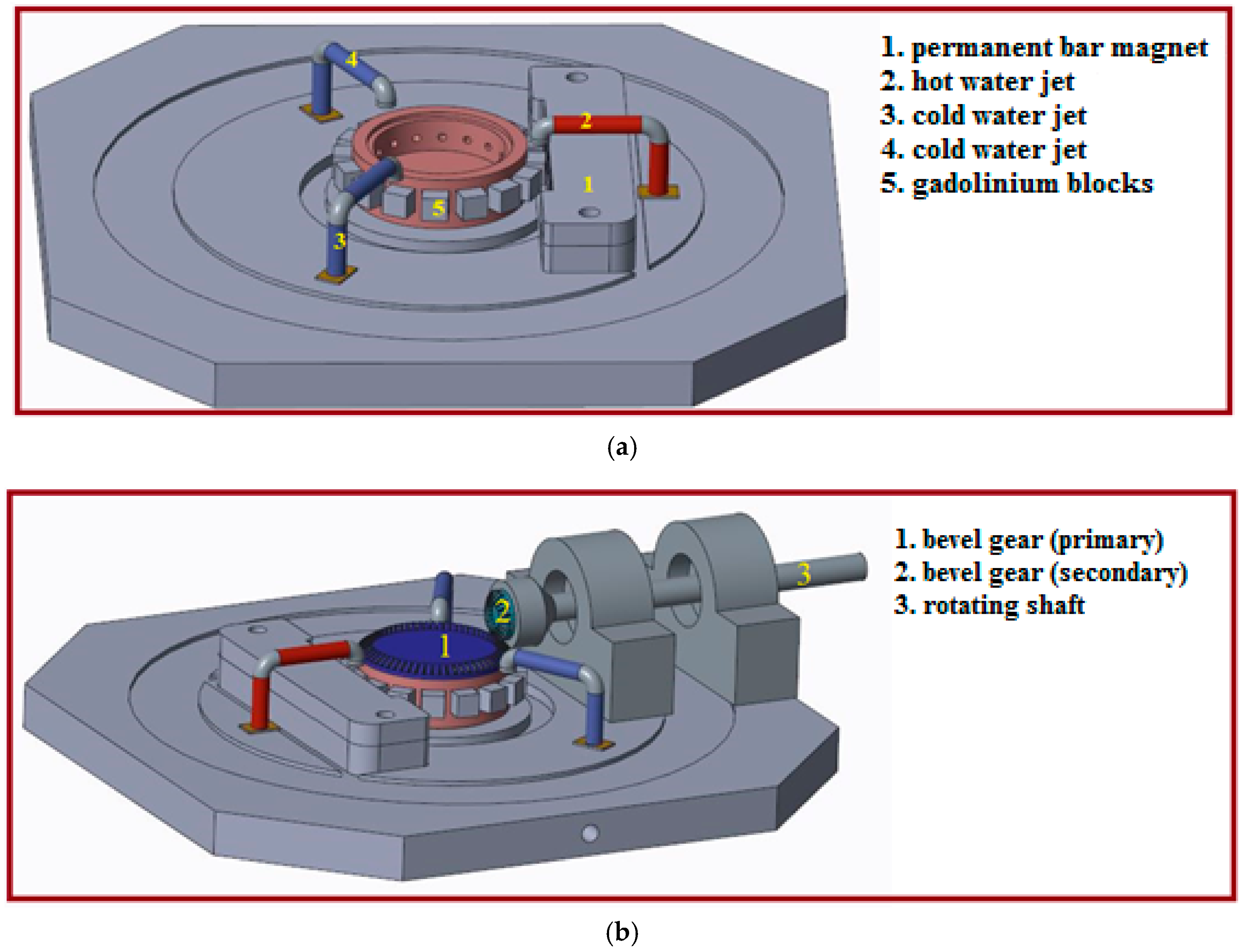
The hybrid (TENG-EMG) disk generator produces electricity when there is a relative motion between the rotor and stator parts of the TENG and EMG. The thermomagnetic Gd engine provides rotation to the NG when the hot and cold water jets impinge on the Gd blocks. The Gd block has a curie temperature very near to room temperature, and it changes its magnetic properties, i.e., from ferromagnetic to paramagnetic, depending on its temperature controlled by the water jets.
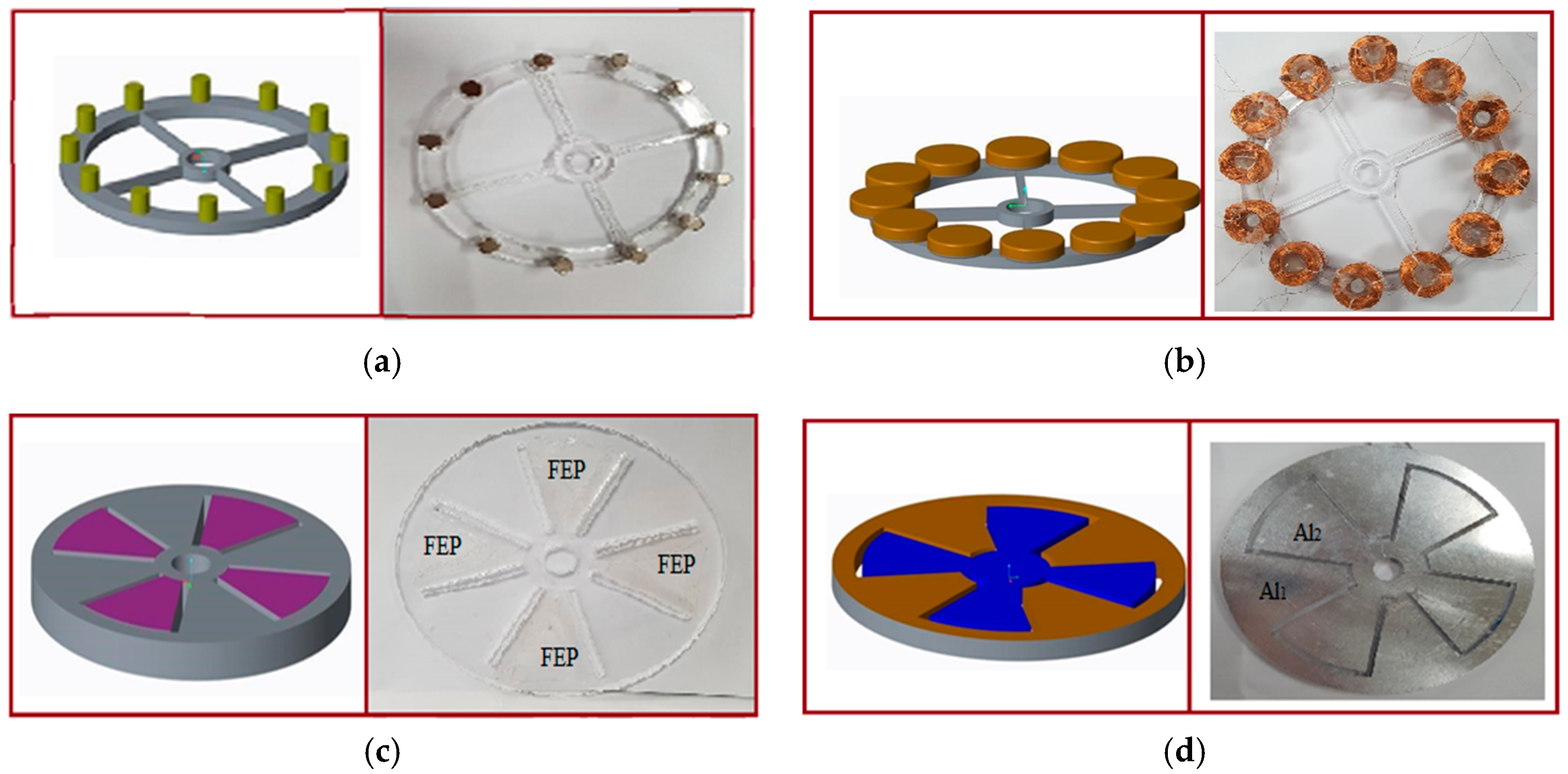
The rotor of the hybrid generator consists of two layers (1–2) as shown in
Figure 3a. Layer 1 is the EMG part with 12 magnets while layer 2 is the TENG part, consisting of a disk with a diameter of 120 mm, which is covered by the FEP as a triboelectric material. The stator of the hybrid NG also consists of two layers (3–4) as shown in
Figure 3b. Layer 3 is aluminum electrodes while layer 4 consists of the corresponding 12 serially connected coils, fixed in alignment with the magnets.
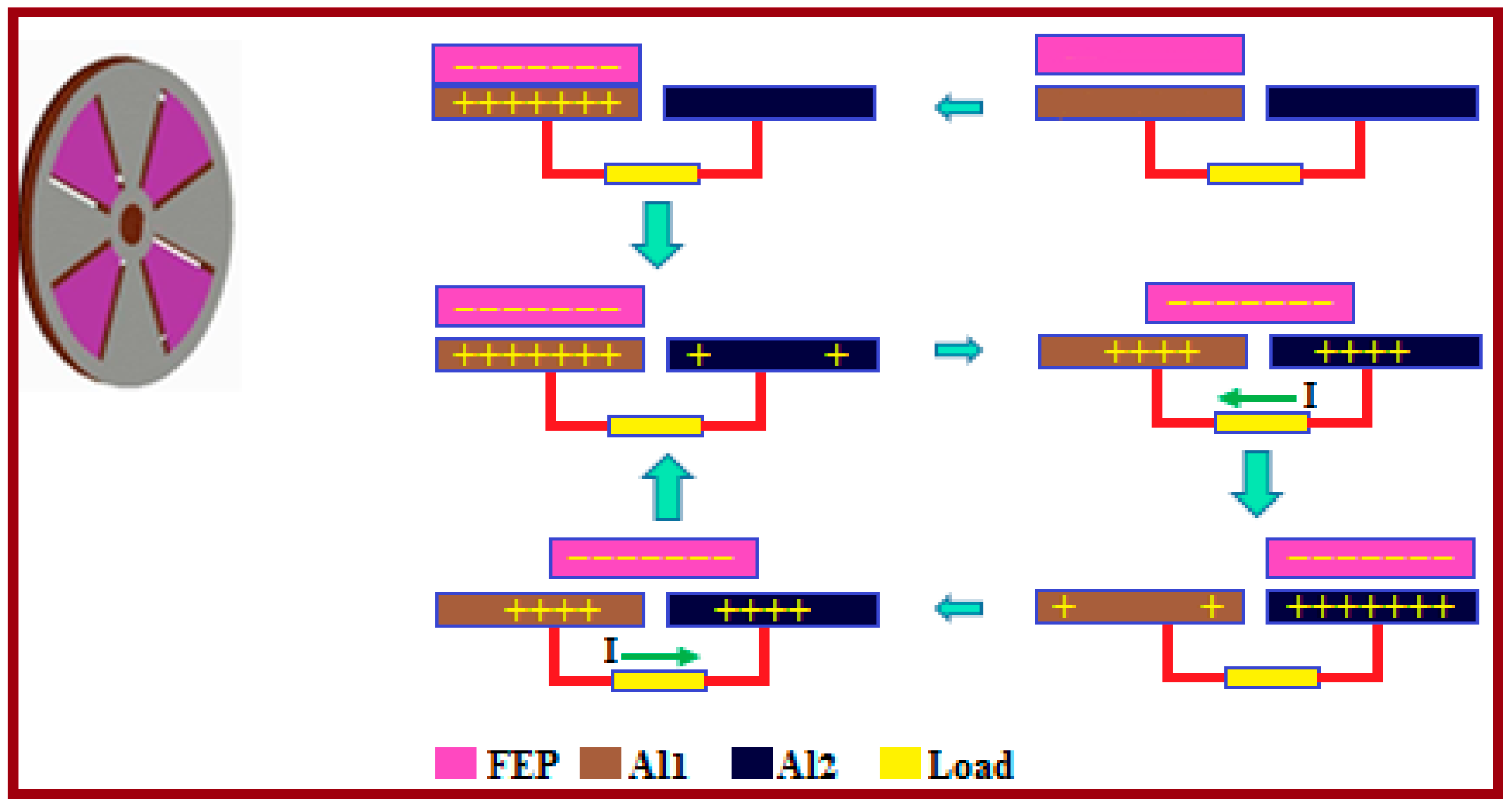
The total output energy produced from this generator is divided into two parts: (1) The energy produced by the TENG part; and (2) the energy produced by the EMG part. The TENG produces electricity when both triboelectric surfaces (FEP and Al) are first brought into contact to produce charges due to the difference in the electron affinity between the Al and FEP. This is called the initial contact electrification step in which negative charges appears on the FEP layer and positive charges on the aluminum electrode [
19,
20,
21] as shown in
Figure 4. In the next step, the two layers (FEP and Al) are brought away from each other, leaving a small air gap between them.
When the FEP portion rotates from Al
1 to Al
2, the electrons will move from Al
2 to Al
1 to cover the potential difference on the FEP surface produced by the negative charges (step II). When the FEP reaches the overlapping position of Al
2, most of the electrons will move to Al
1, which produces the majority of the positive ions on Al
2 (step III). In the next step, the FEP segment will start its motion back toward the adjacent Al
1 segment. As such, the electrons will travel back from Al
1 to Al
2, producing an output current in the opposite direction (step IV) until the FEP segment reaches the primary position. The working principle of the TENG part is shown in
Figure 4.
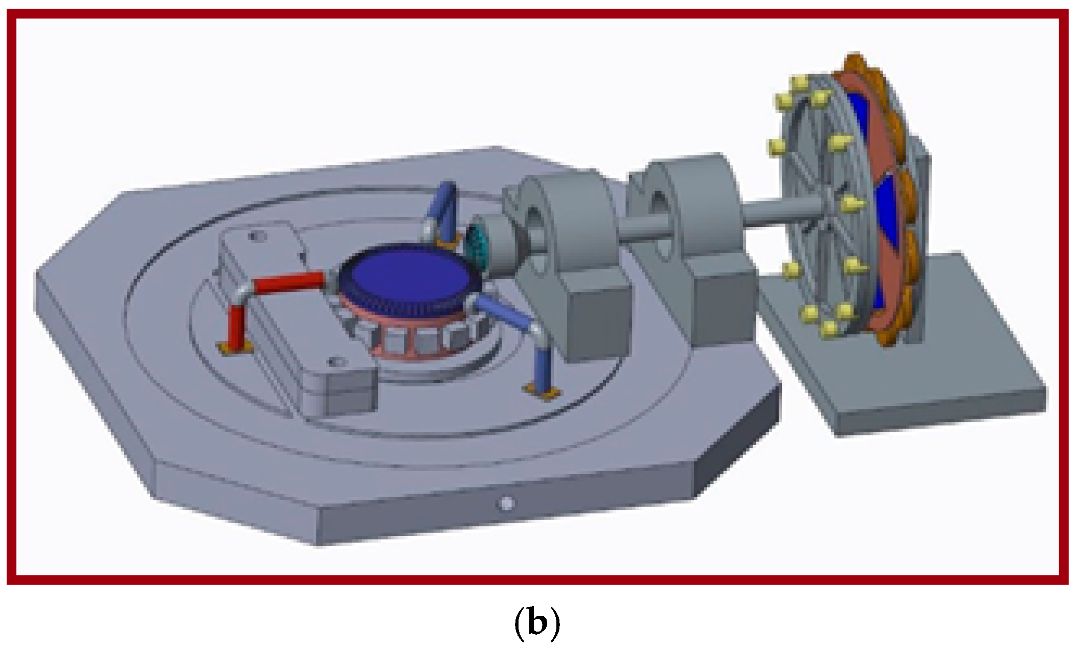
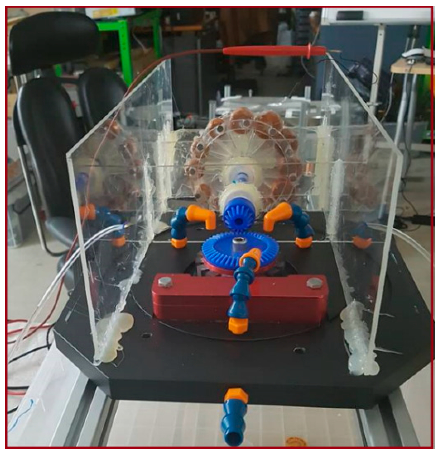
In the experiment, the rotational parts were driven by the thermomagnetic engine at a rotational speed of 251 rpm, and the stationary part was fixed just adjacent to the rotational parts. The schematic diagram and the fabricated model of the whole integrated system (thermomagnetic engine and NG) are shown in
Figure 5 and
Figure 6.
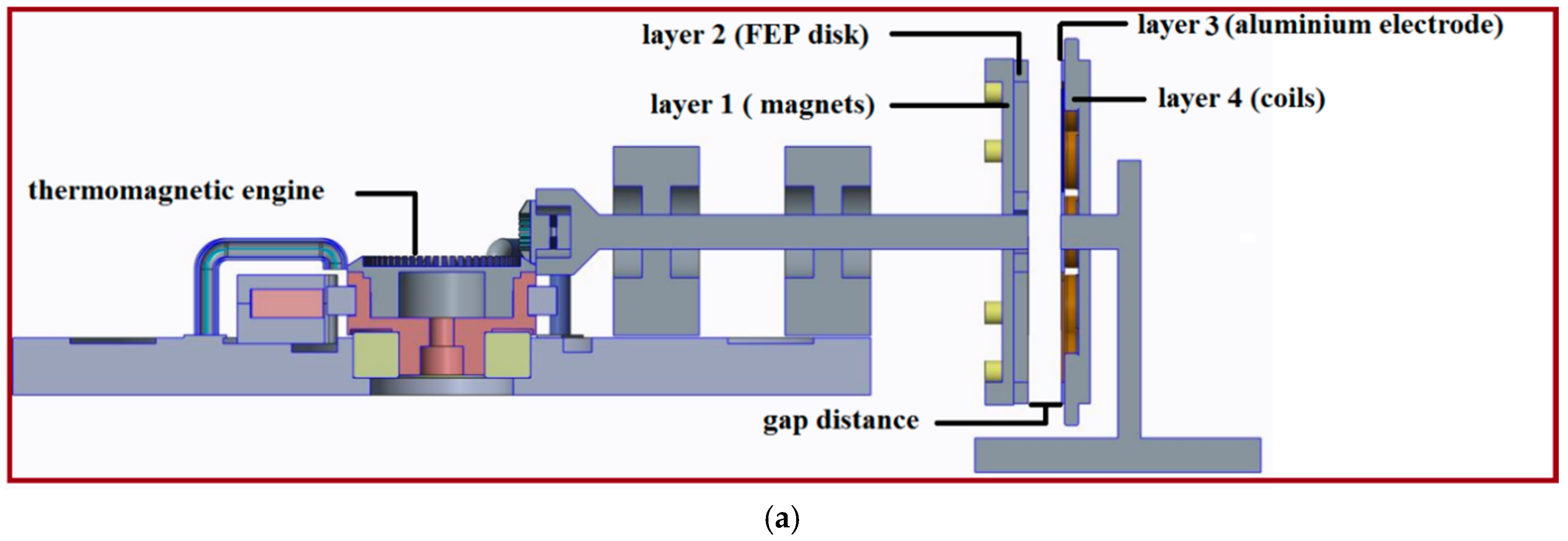
As shown in
Figure 5a, the triboelectric generator (layer 2 and layer 3) is sandwiched between the EMG (layer 1 and layer 4). Layer 2 is a thin FEP disk, which is adhered to layer 1 (magnets disk). Layer 1 and layer 2 make up the rotor part of the hybrid (TENG, EMG) generator. Layer 3 is a 1 mm-thick disk-shaped aluminum electrode mounted on layer 4 (coil disk). Layer 3 and layer 4 make the stator part of the hybrid (TENG, EMG) generator. The gap distance between the rotor and stator parts was selected based on the output performance of the generator.
The output of the TENG part relies on the surface charge density, surface area of the FEP and Al, and the rotational angular velocity. The EMG produces an alternating current as directed by Faraday’s law of electromagnetic induction based on the periodic change of the magnetic flux in the coils.
The output of the EMG depends on the number of turns (N) of each coil, the internal resistance of the coil (R), and the changing flux, dΦ/dt (rotational speed). The output from both the TENG and EMG were combined for maximum efficiency.
4. Results and Discussion
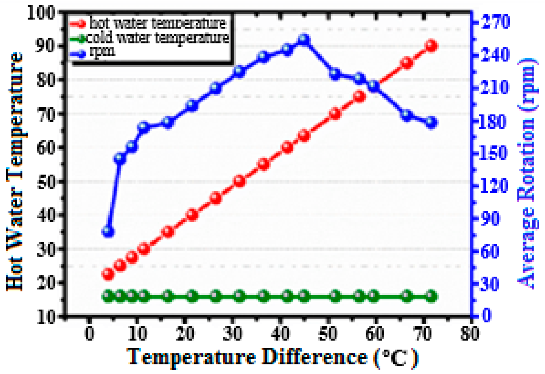
The non-contact sliding mode of the TENG and conventional EMG was experimentally tested for its application to a Gd based thermomagnetic engine to harness low-temperature heat sources. The Gd based thermomagnetic engine was operated at different temperatures between hot and cold water jets. The cold water jet was kept constant at 18.5 °C while that of the hot water was changed from 22.5 °C to 90 °C. The minimum rotational speed of 77 rpm was measured at the temperature difference of 4 °C. Meanwhile, the maximum rotational speed of 251 rpm was observed when the temperature difference between the two jets reached 45 °C, as shown in
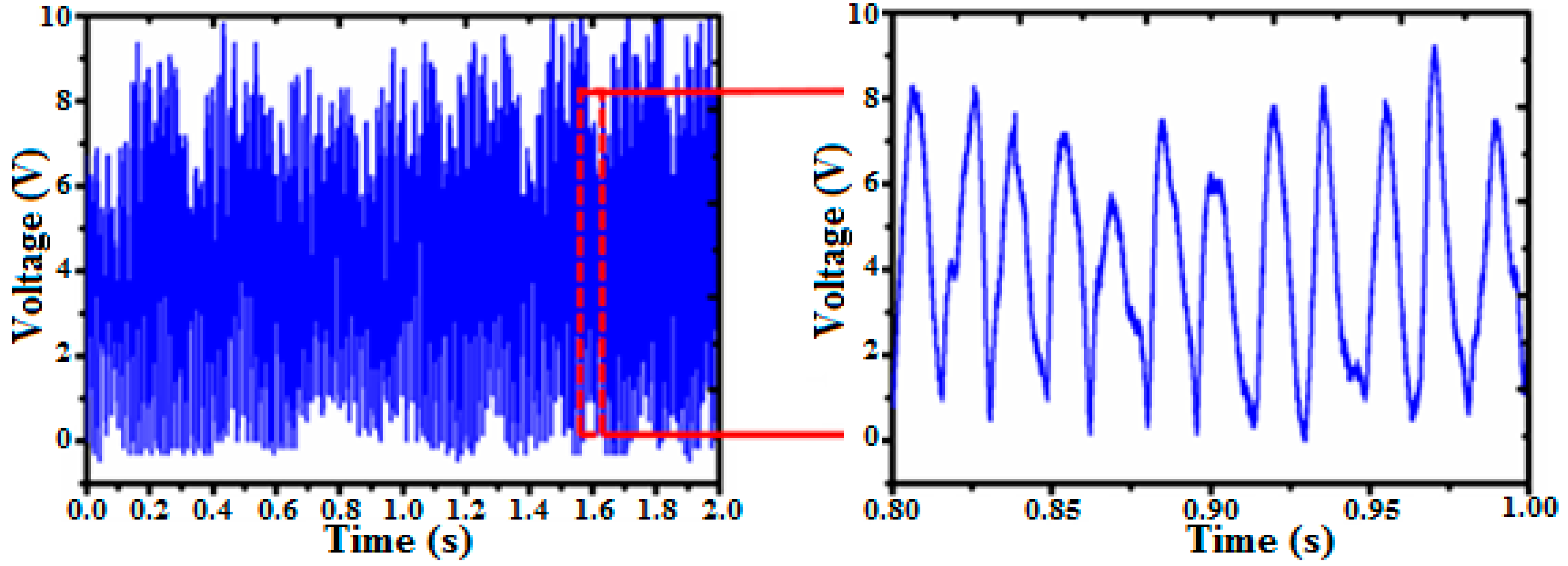
Figure 7. In the experiment, the hybrid (TENG-EMG) generator was integrated with the rotating shaft of the thermomagnetic engine, which efficiently harvested both the triboelectric and electromagnetic effect. The open circuit output voltage was measured by 10 MΩ probe of a DS07052B oscilloscope (Agilent, Santa Clara, CA, USA) while Keysight B2902A (Keysight, Santa Rosa, CA, USA) was used to measure the short circuit current of the generator. The continuous forward and backward sliding motion of the FEP over the Al electrodes produced an AC voltage signal which was converted to a DC signal with a bridge rectifier as shown in
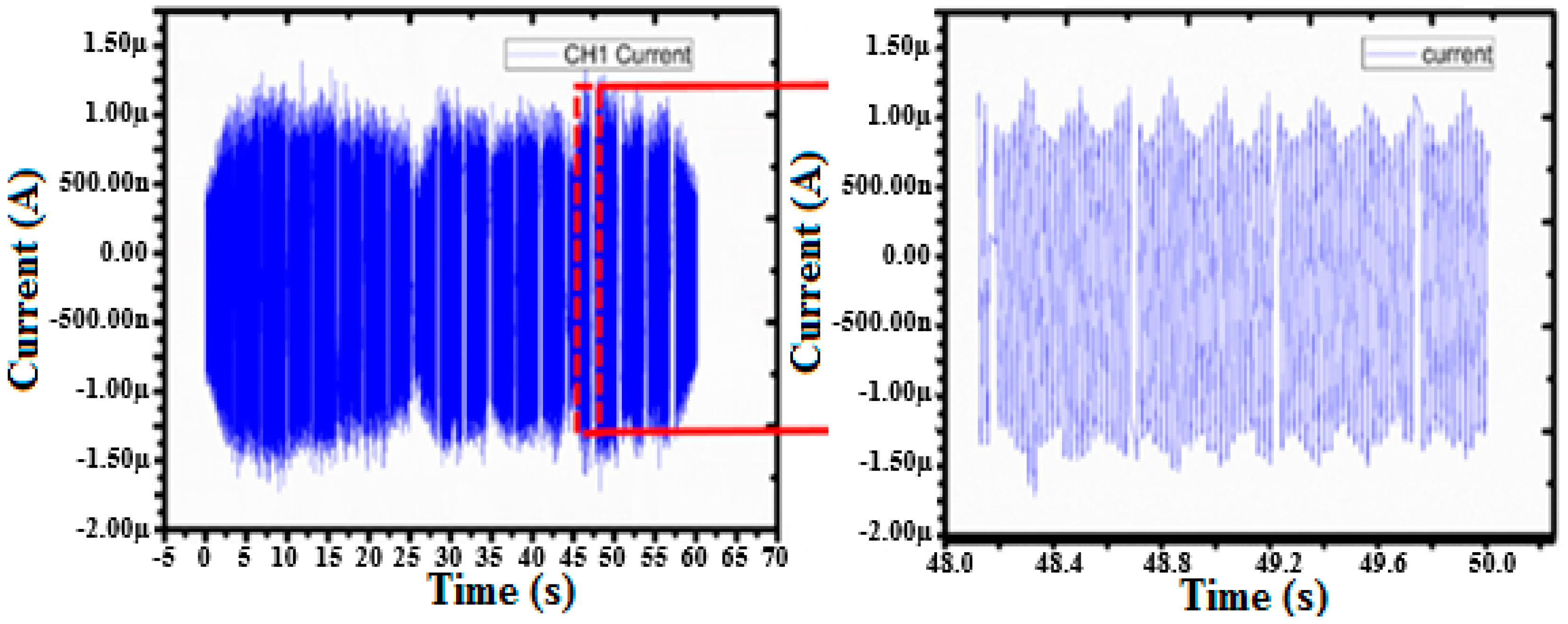
Figure 8. Operated at a continuous rotational speed of 251 rpm for a temperature difference of 45 °C between the hot and cold water jets, the TENG produced an open circuit voltage of 9 V and a short circuit current of 0.9 μA, respectively, with a distance of 1.2 mm between the two triboelectric surfaces. The short circuit current analysis of the TENG is shown in
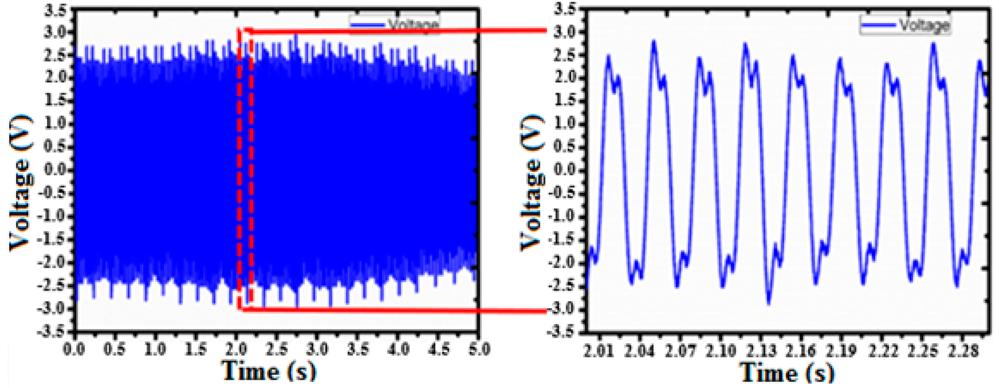
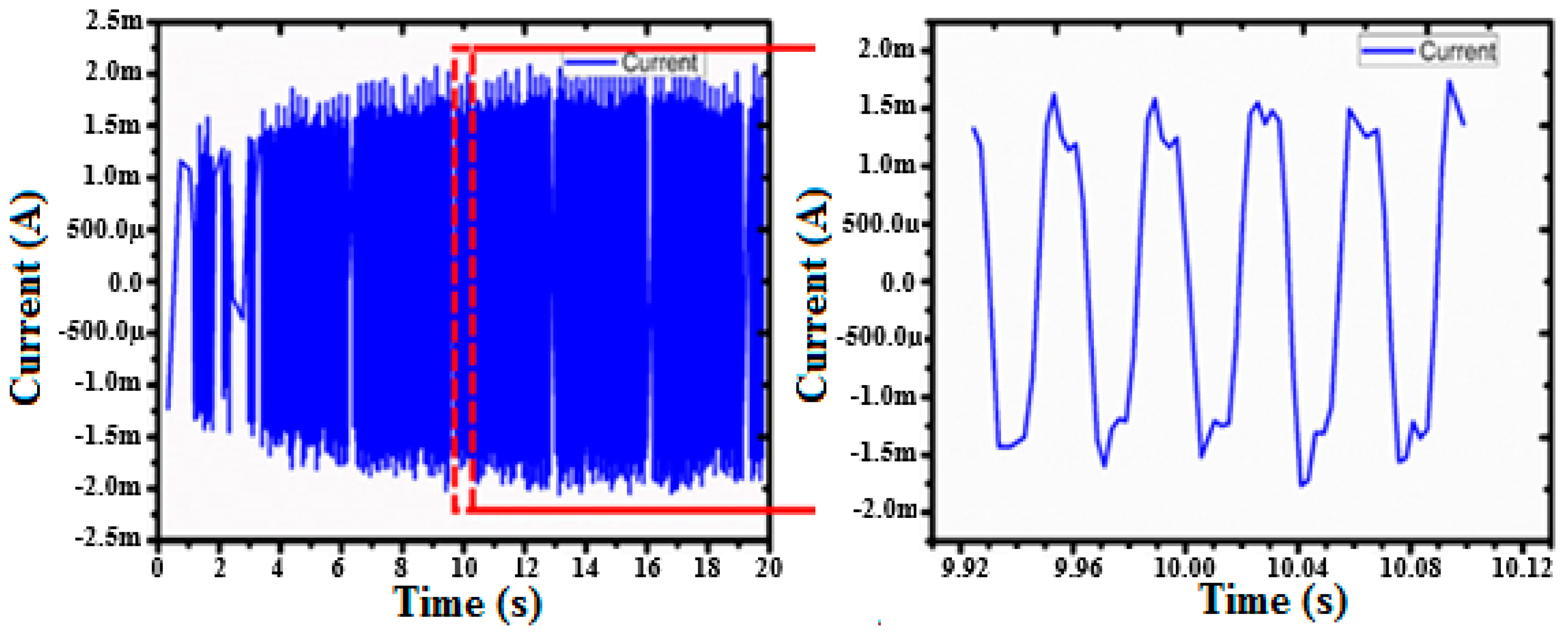
Figure 9. Under the same rotational motion, the EMG produced an average open circuit voltage of 2.3 V and a short circuit current of 1.5 mA, respectively, as shown in
Figure 10 and
Figure 11. The magnets and coils were 2.5 mm apart from each other when the experiments were carried out for the output performance of the EMG.
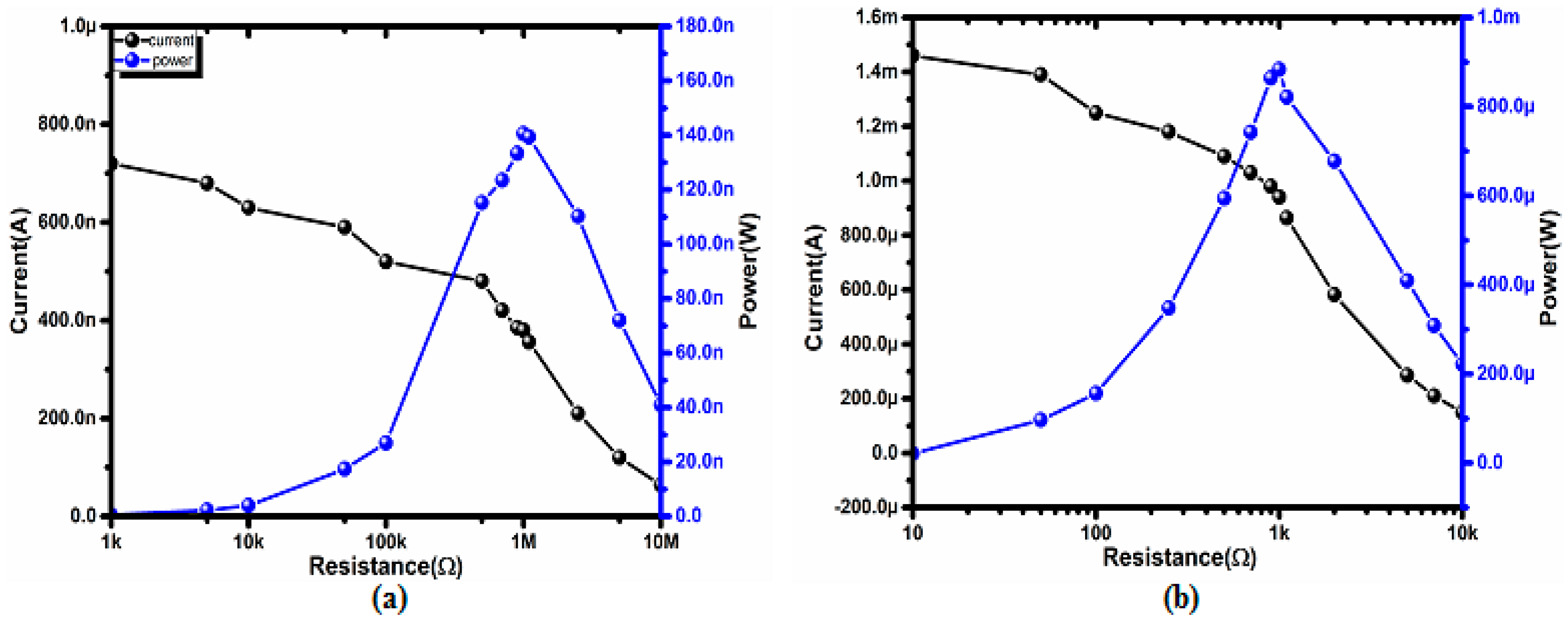
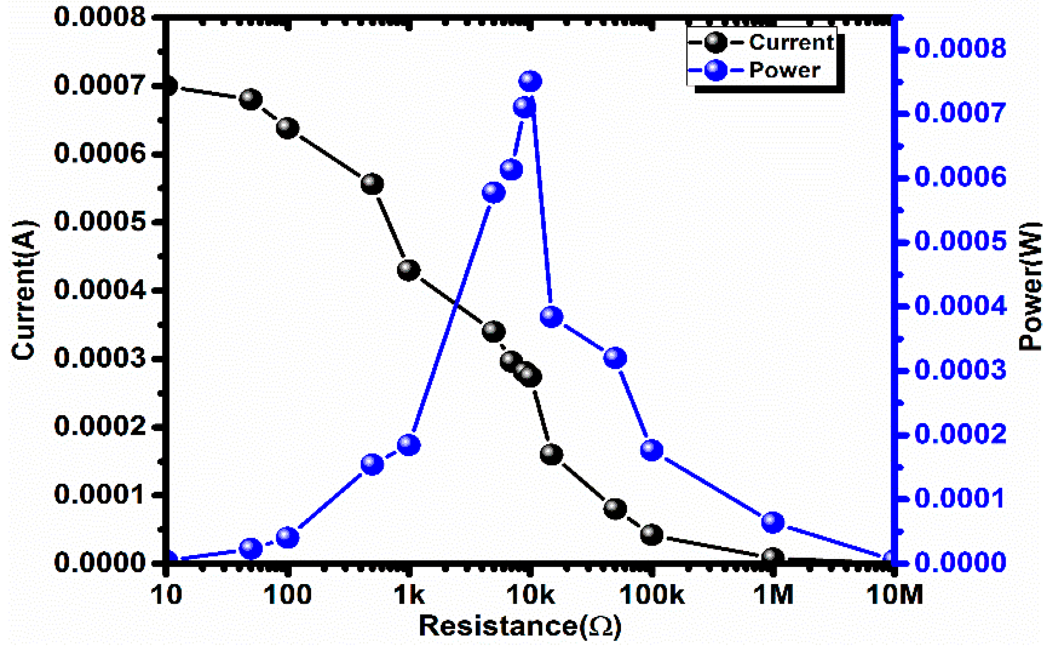
Figure 12a,b displays the dependence of the resistance on the output current and the corresponding output powers of both the TENG and EMG, respectively. The output currents of the TENG and EMG decreased with increasing load resistance, whereas the output electrical power of both generators initially increased and then decreased under a large loading resistance. The largest output power values of the TENG and EMG were approximately 0.144 μW and 0.88 mW at a loading resistance of 1 MΩ and 1 kΩ, respectively, as shown in
Figure 12.
The optimum spacing’s for the TENG and EMG were selected to be 1.2 mm and 2.5 mm, respectively, after carefully analyzing the rotational speed and the output voltage. As far as the TENG is concerned, the various gap distances (ranging from 0.5 mm to 2 mm) between the FEP disk and aluminum electrodes were analyzed before finalizing the optimum value; see
Figure 13a. The initial spacing between the FEP disk and the aluminum electrodes was selected to be 0.5 mm, but at this gap distance, the rotor occasionally touched the stator because of its wobbling motion when rotating. This caused a substantial decrease in the rotational speed and hence resulted in a low output voltage. The maximum output voltage of 9 V was observed at a gap distance of 1.2 mm, where the rotor achieved its maximum rotational speed of 251 rpm without interacting (touching) the stator. However, the voltage started to decline when the gap distance exceeded 1.2 mm. This is due to the fact that there was no noticeable increase in the rotational speed (almost the same as in the case of 1.2 mm), but the larger gap distance resulted in a weaker electrostatic interaction between the electrodes.
In conclusion, a gap distance of less than 1.2 mm caused a decrease in the rotational speed due to unwanted occasional contact between the rotor and stator, resulting in the degradation of the TENG’s output performance. Similarly, its performance also degraded when the gap distance was increased beyond 1.2 mm. This is because a further increase in the gap only weakened the electrostatic interaction between the electrodes without any increase in the rotational speed of the shaft driving the generators. The relation between the output performance of the TENG and the gap distances is shown in
Figure 13b.
The gap distance of the EMG was dictated by that of the TENG as the latter was designed to be located between the coils and the magnets making up the EMG, as shown in
Figure 5a. In other words, the optimum gap for the EMG is inherently dependent on the spacing of the TENG. That is, a change in the spacing of the TENG will result in a change in the gap distance between the magnets and coils. As shown in
Figure 13a, the Al electrode and FEP film together require at least 1.3 mm spacing available for installation. Taking this into consideration, the performance of the EMG was analyzed for the gap distances between 1.5 mm and 3 mm as shown in
Figure 13c. The optimum spacing of 2.5 mm for the EMG was obtained when the gap distance of the TENG was maintained at 1.2 mm. At a rotational speed of 251 rpm, the EMG produced its maximum output. As aforementioned, a decrease in the spacing to less than 2.5 mm resulted in undesirable interaction between the TENG components, leading to disruptions in the rotation of the shaft driven by the thermomagnetic engine and hence poorer performance for both generators. Similarly, the output performance of the EMG decreased when the gap distance exceeded 2.5 mm. When the spacing for the TENG increased beyond 1.2 mm, the gap distance between the rotor (magnets) and the stator (coils) of the EMG exceeded 2.5 mm, causing weaker magnetic fluxes through the coils of the EMG and hence impairing the EMG’s performance. This can be readily observed in
Figure 13c, where the relationship between the gap distance and the output voltage of the EMG is given.
The EMG produced high current output with low impedance whereas the TENG generated low current output with high impedance. Due to the huge difference in the impedance of the two generators, it was difficult to connect them directly in parallel. To deal with this impedance mismatch and to get the optimum electrical output in terms of the voltage and current, transformers were designed for both generators. The turn ratio of the transformers was determined by Equation (3), as given below:
were
Vs and
Vp are the voltages of the secondary and primary coils, respectively.
As compared to the TENG (~1 MΩ), the EMG showed much smaller impedance (~1 kΩ). To accomplish impedance matching of the generators, the TENG was connected to a transformer with a turn ratio of 1.8:1. Similarly, the EMG was connected to a transformer with a turn ratio of 1:2:1. After connecting the generators (EMG, TENG) to the transformers, the matched resistance was modulated to about 10 kΩ. A series of measurements demonstrated the capability of the hybrid NG, producing the maximum electrical output power of 0.75 mW at a loading resistance of 10 kΩ as shown in
Figure 14.
Figure 15 shows the circuit diagram to measure the performance of the hybrid generator where the EMG and TENG are connected in parallel. As shown in
Figure 16 and
Figure 17, the hybrid generator was capable of producing an open circuit voltage of 5 V and a short circuit current 0.7 mA, respectively. The mechanical power of the system (thermomagnetic engine) was determined by measuring the torque and angular velocity, which is given as:
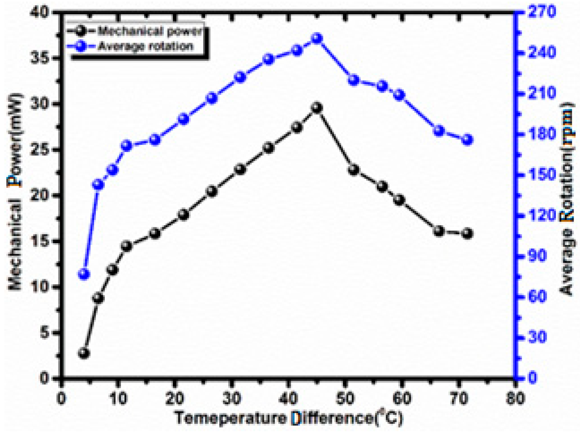
In
Figure 18, the mechanical power of the system delivered by the thermomagnetic engine is given at various temperature differences between the hot and cold water jets. The maximum mechanical power of 29.5 mW was observed at the temperature difference of 45 °C between the two jets, when the rotational speed was 251 rpm.


