Abstract
Surface permanent-magnet machines are widely used in different applications, from industrial automation to home appliance and electrical traction. Among any possible machine topology, the fractional-slot surface permanent-magnet one has gained increasing importance, because of its high torque density, low cogging torque, extended flux weakening capability and high efficiency. In addition, fractional-slot machines are attractive for tooth concentrated windings, which allow some optimized manufacturing solutions such as modular stator tooth and high slot filling factor, which result in copper volume reduction; cost reduction, and lower stator parasitic resistances. The slot–pole combination is one of the most important design parameter and, as shown in this paper, it affects performances and the robustness of the machine with respect to the manufacturing imperfections. In the literature, slot–pole combinations are optimized at design phase by finite-element analysis relying on a healthy machine model. The original contribution of this paper is a design for reliability method that models manufacturing defects and includes them at design phase in the optimization process of slot–pole combinations. A method is presented that allows defining the optimal design parameters for maximum performances and robustness towards unavoidable imperfections caused by tolerances of the manufacturing process.
1. Introduction
Surface permanent-magnet (SPM) machines are widely used in different applications, from industrial automation to home appliance and electrical traction. Among any possible machine topology, the fractional-slot SPM has gained increasing importance, because of its high torque density, low cogging torque, extended flux weakening capability and high efficiency.
On the other hand, permanent-magnet machines are prone to defect and suffer from scarcity of high-quality magnets. Moreover, surface permanent-magnet (SPM) synchronous machines have generally been considered to be poor candidates for achieving wide ranges of constant-power operation by means of flux weakening [1]. A proper design approach can be used to achieve optimal flux-weakening operations in SPMs. The use of concentrated fractional-slot stator windings significantly increases the machine inductance in order to achieve the critical condition for providing wide speed ranges of constant-power operation.
The slot–pole combination deeply affects characteristics and performance of synchronous SPM machines, in terms of stator air gap MMF waveform and amplitude, machine periodicity, back-EMF harmonic content, cogging torque, efficiency, uncompensated radial electromagnetic force and power factor [2,3,4].
Generally, the choice of the slot–pole combination relies on the specific design objectives and machine dimensions [5]. For example, a maximum achievable torque for a given volume design, compared to a cost minimization design may give, as output design, a different optimal slot–pole ratio.
In the literature, the performance of slot–pole combinations is often compared assuming optimal operating conditions without including also typical imperfections [6,7]. The manufacturing process naturally introduces some unavoidable defects related to mechanical tolerance or to permanent-magnet (PM).
This study aimed to extend the analysis of the slot–pole combination on machine performance, adding manufacturing imperfections at design level. Specifically, this study investigated how the slot–pole combination affects the robustness of electrical machines in case of static eccentricity, dynamic eccentricity, demagnetization, deviation of magnetic axis and dislocation of permanent-magnet. The manufacturing imperfections were considered within standard tolerance ranges, usually provided by manufacturers.
Several slot–pole combinations were compared on a common reference frame with fixed: machine volume, external diameter of 92 mm (typical of a 100 mm machine size for automation) and a stack length of 100 mm, flux density and current density. The following slot–pole combinations were evaluated: 6 slots–4 poles double layer (DL) and single layer (SL); 9 slots–8 poles DL; 9 slots–10 poles DL; 12 slots–10 poles SL and DL; and 12 slots–14 poles SL and DL. The number of winding layers affects MMF harmonic content too and hence the machine performance: DL machines feature better MMF harmonic content than SL machines [8]. Therefore, DL and SL structures for a given number of slots were investigated whenever it was feasible.
The selected slot–pole combinations are widespread in industrial automation, for example as axis control units and electric hand operating tools. In addition, further slot–pole combinations can be derived, as an example, the 24 slots–20 poles can be obtained from 12 slots–10 poles.
The analysis and optimal choice of slot–pole combination are tools for design for reliability. The machine was designed to reduce the impact of manufacturing defects and to be quite robust against faults.
This paper is organized as follows: Section 2 highlights the importance of the slot–pole combination on the machine performance. Section 3 shows the optimization process of healthy machines where the magnetic circuit of each slot–pole combination was optimized by 2D-FEA keeping the same flux density and considering an ideal machine design. As shown in Section 4, the machine performance was assessed by the set of benchmarks in Table 1. The robustness analysis against manufacturing defects is presented in Section 5. A performance comparison between healthy and faulty machine was made and the results are reported in Section 6.

Table 1.
Benchmarks.
2. The Slot–Pole Combination
The choice of the slot–pole combination has a strong impact on machine performance. The authors of [9] showed how the slot–pole combination influences machine performance considering the power factor as one of the more important parameter. They pointed out the relationship between the minimum value of inductance of fractional-slot machines and the slot–pole combination: if the machine inductance increases, the machine power factor will decrease and vice versa.
The term fractional-slots refers to stator windings with slot-per-phase-per-pole () values less than one. Compared to the traditional distributed winding, this arrangement is attractive due to its intrinsic low cogging torque and high efficiency due to a minimum content of non-active copper and an extended flux weakening operating range [1]. On the other side, it has a higher harmonic content of the Magneto-Motive Force (MMF) in the air-gap.
The slot–pole combination affects also the periodicity and amplitude of the cogging torque [1,10]. This phenomenon is caused by the interaction between the magnets mounted on the rotor and stator anisotropy due to slotting. The periods of cogging torque depend both on the number of stator slots Q and of rotor poles ; can be computed as the ratio between and the highest common factor (HCF) between Q and (see Equation (1)). Moreover, the cogging torque amplitude is inversely proportional to the number of cogging torque periods: the higher the cogging torque periods , the lower the cogging torque amplitude [10].
The induced air gap MMF is also deeply affected by slot–pole combination, specifically fundamental and higher-order harmonics have different amplitudes for different slot–pole configurations, given the same electrical machine frame. Figure 1 shows the MMF spectra for different double-layer slot–pole combinations, supplying the machine with a fixed value of three-phase currents. MMF were computed by FEA, while their spectra were computed by FFT.
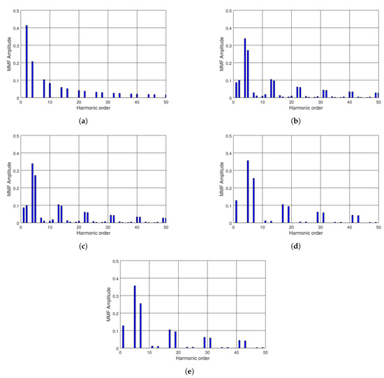
Figure 1.
Magneto-Motive Flux (MMF) spectra for different double layer slot–pole combinations: (a) MMF of 6-4DL; (b) MMF of 9-8DL; (c) MMF of 9-10DL; (d) MMF of 12-10DL; and (e) MMF of 12-14.
Table 2 and Table 3 compare slot–pole combinations in terms of different machine parameters: cogging torque periods , , winding factor which could be used as an index for machine performance and two different total harmonic distortions (THD) of the MMF. includes only odd multiples harmonics of the fundamental frequency interacting with MMF rotor harmonics, thus it could be considered an index of the torque ripple [2]. includes any harmonic order of stator MMF and it could be considered an index of machine rotor losses. THD were computed using the following relationships.
Table 2.
Analyzed slot–pole combinations (a).
Table 3.
Analyzed slot–pole combinations (b).
Simulation results confirm that the harmonic content of double layer winding configurations outperformed single layer winding configurations. In addition, when the was equal to , the winding factor was the lowest () and the MMF Total Harmonic distortion related to torque ripple was at the highest level, thus confirming results in [11].
3. Machine Optimization
The optimization of machine lamination aims at balancing the exploitation of magnetic circuits, towards the best flux density, being the different slot–pole combinations the degree of freedom. An iterative design was made to reach optimal values (maximum or minimum) for benchmarks in Table 1.
It is worth mentioning that only the mean torque was maximized, while all the other performance figures were minimized.
During the optimization process, the following design variables were kept constant: machine geometry, external diameter, lamination material, type of magnet, utilization coefficients of iron and copper. The variables in Table 4 were modified. The maximum stator flux density was fixed between and . Usually, mechanical constraints are more restrictive than magnetic ones, therefore the stator yoke was defined considering a minimum thickness for a reasonable mechanical strength.
Table 4.
Variables.
Table 5 shows the values of optimized lamination parameters and Figure 2 the FEA flux density distributions of slot–pole combinations.
Table 5.
Parameters of Healthy Slot-Pole Combinations.
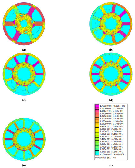
Figure 2.
Distribution of magnetic flux density of optimized machines: (a) 6-4; (b) 9-8; (c) 9-10; (d) 12-10; and (e) 12-14.
4. Performance of the Healthy Combinations
The optimization process was carried out on two different structures of fractional-slot SPM machines: double layer and single layer winding with radial edges permanent magnets, which are referred to as and , respectively. For each structure, some parameters were evaluated for different slot–pole combinations, which can be classified under three categories: mechanical (force and torque), mass, and electrical parameters.
For double layer machines, the torque ripple decreased with an increasing number of slot and poles, while the THD of back-EMF was not directly related to the number of slot and poles (see Table 6 and Table 7). The mean torque was around 8 Nm, for all combinations, except for the 6-4 combination that featured the lowest value around 6.3 Nm. The lowest value of cogging torque Was associated to the 9-8 and 9-10 slot–pole combinations; however, these slot–pole combinations were affected by magnetic unbalance, as shown by the presence of radial force as high as 347 N for 9-8 slot–pole combination (Table 6).
Table 6.
Performance of healthy slot–pole combinations, Part I.
Table 7.
Performance of healthy slot–pole combinations, Part II.
For single layer machines, mechanical performances were lower than for double layer machines. Moreover, the 6-4 featured a radial force component, which did not appear in the 6-4 double layer machine (Table 8 and Table 9).
Table 8.
Performance of healthy slot–pole combinations, Part I.
Table 9.
Performance of healthy slot–pole combinations, Part II.
Since double layer machines outperformed single layer machine, the robustness analysis to manufacturing defects was made only for DL slot–pole configurations.
5. Analysis of Robustness to Manufacturing Defects
The validation of optimization results is usually made by experiments on a machine prototype. Experimental results can be quite different from simulation results (made by FEA), because of unavoidable manufacturing defects, intrinsically produced during production and assembly. The analysis of manufacturing defects at simulation level could pave the way for design for reliability, largely reducing design burden and time-to-market. Some authors investigated the use of FEA to compare the behavior of healthy and faulty machines, where the faults are manufacturing defects. Some authors investigated the impact of different slot–pole combinations on few benchmarks, such as: cogging torque [12,13], or radial force [14,15]. Other authors compared healthy and defective machines i to define a set of diagnostic indexes, that can effectively identify specific faults, e.g., demagnetization [16].
This study extended the optimization process at FEA level to compare different slot–pole combinations in terms of robustness towards manufacturing defects, beyond performance benchmarks: mean torque, torque ripple, cogging torque, radial force, and THD of back-EMF (Table 1).
The manufacturing defects were modeled by FEA, using their typical statistic distributions. Specifically, mechanical defects were modeled with a deterministic function, while magnetic defects were modeled with a Gaussian distribution.
The robustness analysis of manufacturing defects was made for different type of defects: mechanical defects (Section 5.1) and magnetic defects (Section 5.2). Section 5.3 reports the impact of manufacturing defects on the performance benchmarks. Section 6 summarizes all the results, comparing healthy and faulty machines with different slot–pole combinations.
5.1. Eccentricity
Static and dynamic eccentricities were investigated as mechanical manufacturing defects. Static eccentricity occurs when the rotor is displaced from the stator geometrical axis, and the rotor is still turning upon its own axis (see Figure 3b). Dynamic eccentricity occurs when the the rotor is turning upon the stator geometrical axis, but not on its own center (see Figure 3c).
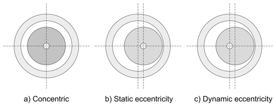
Figure 3.
Examples of a machine: without eccentricity (a); static eccentricity (b); and dynamic eccentricity (c).
FEA simulations were made at 1000 rpm corresponding to a mechanical frequency of Hz. The static eccentricity was modeled, moving the rotor rotational axis by mm toward x-direction, while dynamic eccentricity was modeled moving the rotor block by mm keeping its own center of rotation.
Simulation results show how mechanical defects affect both the waveform and the total harmonic distortion of any performance benchmark. Static and dynamic eccentricities induce additional harmonic components to mechanical quantities, whose amplitude is directly proportional to the fault severity.
For a given mechanical frequency , the static eccentricity induces a second-order harmonic, in this paper referred to as rotor harmonic, which depends on the number of magnetic poles (see Equation (3)). Dynamic eccentricity induces a component, referred to as stator harmonic, which depends on number of stator teeth Q, as shown by Equation (4).
Figure 4 compares the harmonic spectra of the radial force of the 9-8DL and 12-14DL slot–pole combinations under healthy conditions and with a static eccentricity of mm, computed by FEA simulations.
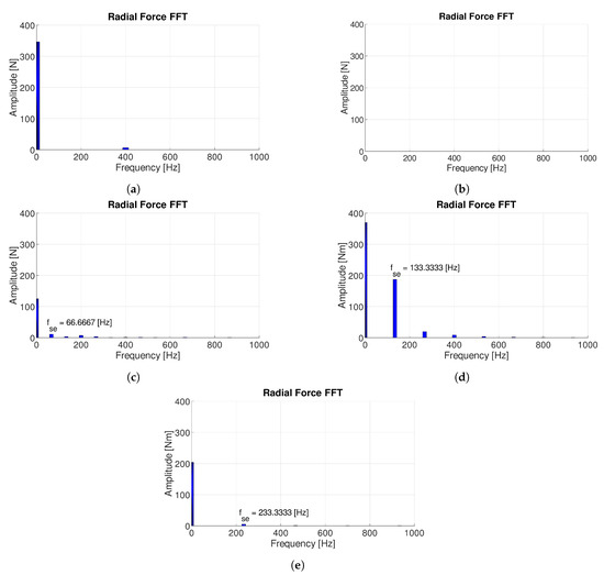
Figure 4.
FFT of the radial forces: 9-8DL (a); 6-4DL and 12-14DL slot-pole combination without static eccentricity (b); 6-4DL (c); 9-8DL (d); 12-14DL slot-pole combinations with static eccentricity of 0.2 mm (e).
Radial force is the parameter that is mostly affected by mechanical defects because eccentricity may magnetically unbalance the motor. FEA results show that, in the case of static eccentricity, 12-10DL and 12-14DL slot–pole combinations were the most affected in terms of radial force, while, in healthy conditions they, featured a zero radial force. The 9-8DL is naturally magnetically unbalance, thus it haD a high radial force even at healthy condition and was less affected by static eccentricity, as shown in Figure 4d.
Slot–pole combinations 9-8DL and 9-10DL were the most sensitive to mechanical defects. The static eccentricity induced a rotor harmonic at Hz for 9-8DL and at Hz for 9-10DL. Hence, torque ripple and cogging torque were adversely affected by static eccentricity, as shown in Figure 5.
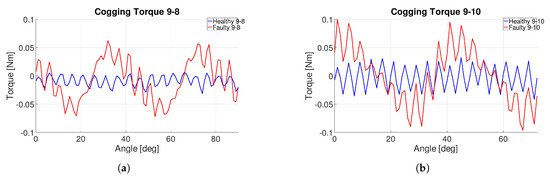
Figure 5.
Cogging torque comparison over a B-EMF period of 9-8DL (a) and 9-10DL (b) with a static eccentricity of mm.
Figure 6 shows the spectra of the mean torque of 9-8DL and 9-10DL slot–pole combinations without and with dynamic eccentricity. Figure 6b,d show clearly the stator harmonic at Hz and the torque ripple harmonic Hz and Hz, respectively, which remained constant.
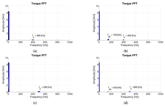
Figure 6.
FFT of the mean torque of 9-8DL and 9-10DL without and with dynamic eccentricity of mm. (a) 9-8DL without defect; (b) 9-8DL with dynamic eccentricity; (c) 9-10DL without imperfection; and (d) 9-10DL with imperfection.
5.2. Permanent-Magnet Defects
Few magnetic defects were investigated: reduction of PM coercive field , i.e., demagnetization; deviation of magnetic axis; and dislocation of magnets, i.e., anomalies in the distance of magnets (see Figure 7). The single magnetic defects were applied on any magnetic pole, with a Gaussian distribution over the tolerance range.
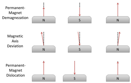
Figure 7.
Permanent-magnet defects: demagnetization, magnetic axis deviation and dislocation.
FEA results show that the slot–pole combinations with higher performances were more sensitive to magnetic defects. Demagnetization increased the radial force component in machines with 12-10DL and 12-14DL slot–pole combinations, as shown in Figure 8. Moreover, it induced a stator harmonic frequency in the spectra of cogging torque.
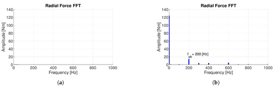
Figure 8.
Radial force FFT of 12-14DL without (a) and with (b) demagnetization.
Magnetic axis deviation and PM dislocation affected the torque ripple for the slot–pole combinations with higher performances. Moreover, they induced an stator harmonic frequency in the spectra of the radial force and of the cogging torque, as shown in Figure 9.
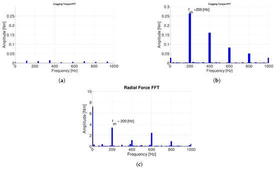
Figure 9.
Cogging torque FFT of 12-14DL: in healthy condition (a); with magnets dislocation (b); and with radial force FFT with magnet dislocation (c).
5.3. Machine Performances vs. Severity of Manufacturing Defects
The main outcome of the paper is the definition of an optimization method that includes manufacturing defects at design phase, by FEA. The optimization method is based on a thorough analysis between fault severity and machine performances, where faults are manufacturing defects, detailed in the previous subsections.
Manufacturing defects were modeled by FEA, using a Gaussian distribution of magnetic defects. The severity of magnetic fault was investigated using as parameter the standard deviation of the Gaussian distribution. Table 10 shows the initial parameters of the Gaussian distributions of magnetic defects.
Table 10.
Bell curve parameter of permanent-magnet imperfections.
According to the analysis presented in Section 5.2, the slot–pole combination 12-14DL was the most sensitive to magnetic defects. Hence, this combination was used to assess the performances towards fault severity. The mean torque decreased with the severity of demagnetization, while this combination was less sensitive to the deviation of magnetic axis and magnet dislocation. Figure 10a,b show that the torque ripple and the cogging torque were both affected by demagnetization and PM dislocation, while Figure 10c shows that the radial force was deeply affected by demagnetization. Hence, it can be concluded that the impact of demagnetization was far more higher than the other magnetic configuration defects.
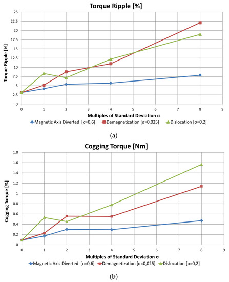
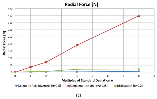
Figure 10.
Correlation between severity of magnetic defects and machine performances of slot–pole combination 12-14DL: (a) trend of torque ripple; (b) trend of cogging torque; and (c) trend of radial force for increasing values of magnetic defects.
As for mechanical defects, fault severity was assessed relying on a deterministic model: eccentricity was increased by steps of mm. Here, two slot–pole combinations were used, based on results in Section 5.1: 9-8DL and 12-14DL. In terms of mean torque, 12-14DL was more sensitive to mechanical fault severity than 9-8DL (Figure 11a). In terms of cogging torque 9-8DL, was more sensitive to mechanical fault severity than 12-14DL (Figure 11b). In terms of radial force, 12-14DL was more sensitive to mechanical fault severity than 9-8DL, as already reported in Section 5.1.
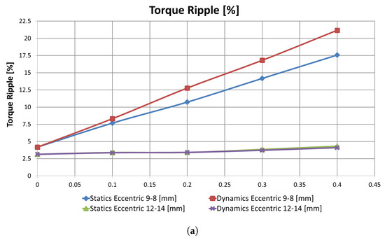
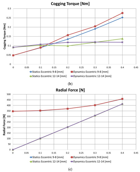
Figure 11.
Correlation between severity of mechanical defects and machine performances of slot–pole combinations 9-8DL and 12-14DL: (a) trend of torque ripple; (b) trend of cogging torque; and (c) trend of radial force for increasing values of mechanical defects.
6. Design for Reliability: Robustness Analysis towards Manufacturing Defects as a Function of Slot–Pole Combinations
The proposed method is detailed here. The robustness analysis was made investigating the effects of all defects, applied at the same time. Table 11 reports the severity of the manufacturing defects used for the analysis. The ranges of defects were based on the tolerance intervals declared by manufacturers.
Table 11.
Severity of defects used for robustness analysis.
Then, the performances of healthy and faulty machines for different slot–pole combinations were compared in terms of the benchmarks in Table 1. FEA results are summarized by Kiviat diagrams, which can show more than three parameters on a 2-D plane, being the number of vertex of the polygon the number of parameters.
Figure 12a,b rank the different slot–pole combinations in terms of benchmarks. The ranking is based on the areas of the polygons: the best slot–pole combinations feature a larger areas, and vice versa. Because of different scales, the benchmarks were normalized according to their standard deviations, as shown in Equations (5) and (6), where and are the maximum and minimum values the statistical series x, respectively. Specifically, the mean torque was normalized according to its maximum value (Equation (5)), while the other parameters were normalized according to their minimum values (Equation (6)).
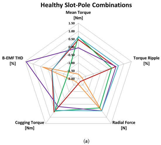
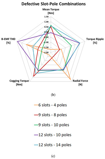
Figure 12.
Kiviat diagrams of healthy machines for different slot–pole combinations (a) and of faulty machines (b); and slot–pole legend (c).
Kiviat diagrams allow visualizing machine performances and robustness toward manufacturing defects. To compare different slot–pole combinations, the normalized parameters reported in the Kiviat diagrams were aggregated in a single index, called Total Performance Index (TPI), for both the healthy and defective cases, as shown in the first and second columns of Table 12.
Table 12.
Slot–pole combination comparison according to total performance index.
For a given slot–pole combination, the TPI was computed as the algebraic sum of the normalized benchmarks and the areas of the polygons in Kiviat diagram were related to TPI value. The best slot–pole combination were those with the higher TPI. The identification of the most robust combinations was carried out by comparing the subtraction of the healthy and defective TPI; the results are shown in the third column of Table 12.
According to Table 12, the TPI of the 12-10DL and 12-14DL featured the largest area and maximum TPI, while 6-4DL was the worst, as shown also in Figure 12a. On the other hand, in the case of defective machines, the 6-4DL exhibited an improvement in terms of TPI, while 12-10DL and 12-14DL remained stable and the 9-8DL and 9-10DL showed decreasing performance.
7. Conclusions
This paper proposes an optimization method that leads to design for reliability. At design phase, the optimization process selects the slot–pole combination best suited for both performances and robustness towards manufacturing defects.
Starting from healthy slot–pole combinations, manufacturing defects related to mechanical and magnetic parts were modeled and analyzed. These defects were modeled at FEA level, considering a deterministic behavior for mechanical defects and Gaussian distribution for magnetic defects.
Some typical slot–pole combinations were optimized by FEA in terms of their magnetic circuit and then they were ranked with respect to performance benchmarks. A case study is presented for a fractional-slot SPM machine.
Some insights from the case study are here summarized:
- Static and dynamic eccentricities induce new components in the spectra of mechanical quantities. Static eccentricity induces a frequency component proportional to the number of poles , while dynamic eccentricity induce a frequency component proportional to the number of stator teeth Q.
- Radial force is the most sensitive performance benchmark to manufacturing defects. Specifically, FEA results show how the radial force is deeply affected both by mechanical and by magnetic defects.
- The 12-10DL and 12-14DL were the best performing machines in both healthy and faulty conditions and they showed the lowest difference in terms of TPI.
- According to the TPI, the 9-8DL was the slot–pole combination mostly affected by manufacturing imperfections.
- Finally, the slot–pole combination with lowest performance at healthy conditions (6-4DL) showed the best improvement in term of performance at defective condition.
Author Contributions
Conceptualization and validation, A.T. and M.D.; data curation, C.B.; methodology; and supervision and writing—review and editing, A.B.
Funding
This research received no external funding.
Conflicts of Interest
The authors declare no conflict of interest.
Abbreviations
The following abbreviations are used in this manuscript:
| SPM | Surface Permanent-Magnet |
| FEA | Finite-Element Analysis |
| MMF | Magneto-Motive Force |
| B-EMF | Back-Electro-Motive Force |
| HCF | Highest Common Factor |
| FFT | Fast Fourier Transformation |
| THD | Total Harmonic Distortion |
| DL | Double Layer |
| SL | Single Layer |
| TPI | Total Performance Index |
References
- El-Refaie, A.M.; Jahns, T.M. Optimal flux weakening in surface PM machines using fractional-slot concentrated windings. Int. IEEE Trans. Ind. Appl. 2005, 41, 790–800. [Google Scholar] [CrossRef]
- Bianchi, N.; Dai Prè, M.; Alberti, L.; Fornasiero, E. Theory and Design of Fractional-Slot PM Machines, 1st ed.; CLEUP sc; Coop. Libraria Editrice Università di Padova: Padova, Italy, 2007; ISBN 978-88-6129-122-5. [Google Scholar]
- Abdennadher, I.; Masmoudi, A.; Castiello, M.; Bianchi, N. On the effect of the rotor polarity on the performance of fractional Slot SPM machines. In Proceedings of the International Conference on Sustainable Mobility Applications, Renewables and Technology (SMART), Kuwait City, Kuwait, 23–25 November 2015; pp. 1–6. [Google Scholar]
- Deng, A.Q.; Hong, B.S.; Xiao, C.F. Influence of design parameters on cogging torque in directly driven permanent magnet synchronous wind generators. In Proceedings of the International International Conference on Electrical Machines and Systems, Tokyo, Japan, 15–18 November 2009; pp. 1–5. [Google Scholar]
- Fornasiero, E.; Alberti, L.; Bianchi, N.; Bolognani, S. Considerations on Selecting Fractional-Slot Nonoverlapped Coil Windings. IEEE Trans. Ind. Appl. 2013, 49, 1316–1324. [Google Scholar] [CrossRef]
- Min, S.G.; Sarlioglu, B. Design optimization of surface permanent magnet machines with fractional slot concentrated windings. In Proceedings of the International 9th International Conference on Power Electronics and ECCE Asia (ICPE-ECCE Asia), Seoul, Korea, 27–30 May 2015; pp. 707–713. [Google Scholar]
- Liu, Y.; Zhu, Z.Q. Electromagnetic performance comparison of 18-slot/26-pole and 18-slot/10-pole fractional slot permanent magnet surface-mounted machines. In Proceedings of the International 20th International Conference on Electrical Machines and Systems (ICEMS), Sydney, Australia, 1–14 August 2017; pp. 1–6. [Google Scholar]
- El-Refaie, A.M.; Jahns, T.M. Impact of Winding Layer Number and Magnet Type on Synchronous Surface PM Machines Designed for Wide Constant-Power Speed Range Operation. Int. IEEE Trans. Energy Convers. 2008, 23, 53–60. [Google Scholar] [CrossRef]
- Boazzo, B.; Pellegrino, G.; Vagati, A. Multipolar SPM Machines for Direct-Drive Application: A General Design Approach. Int. IEEE Trans. Ind. Appl. 2014, 50, 327–337. [Google Scholar] [CrossRef]
- Bianchi, N.; Bolognani, S. Design techniques for reducing the cogging torque in surface-mounted PM motors. Int. IEEE Trans. Ind. Appl. 2002, 38, 1259–1265. [Google Scholar] [CrossRef]
- Cros, J.; Viarouge, P. Synthesis of high performance PM motors with concentrated windings. Int. IEEE Trans. Energy Convers. 2002, 17, 248–253. [Google Scholar] [CrossRef]
- Gasparin, L.; Cernigoj, A.; Markic, S.; Fiser, R. Additional Cogging Torque Components in Permanent-Magnet Motors Due to Manufacturing Imperfections. Int. IEEE Trans. Magn. 2009, 45, 1210–1213. [Google Scholar] [CrossRef]
- Wu, L.; Qu, R.; Song, B.; Bi, H.; Jing, O.; Yang, G.; Du, C. Analysis of cogging torque in surface permanent magnet machine with manufacturing tolerances. In Proceedings of the International 41st Annual Conference of the IEEE Industrial Electronics Society (IECON), Yokohama, Japan, 9–12 November 2015. [Google Scholar]
- Jia, S.; Qu, R.; Li, J.; Fu, Z.; Chen, H.; Wu, L. Analysis of FSCW SPM servo motor with static, dynamic and mixed eccentricity in aspects of radial force and vibration. In Proceedings of the International 2014 IEEE Energy Conversion Congress and Exposition (ECCE), Pittsburgh, PA, USA, 4–18 September 2014; pp. 1745–1753. [Google Scholar]
- Dorrell, D.G.; Hsieh, M.; Guo, Y. Unbalanced Magnet Pull in Large Brushless Rare-Earth Permanent Magnet Motors With Rotor Eccentricity. Int. IEEE Trans. Magn. 2009, 45, 4586–4589. [Google Scholar] [CrossRef]
- Ginzarly, R.; Hoblos, G.; Moubayed, N. Electromagnetic and vibration finite element model for early fault detection in permanent magnet machine. In Proceedings of the International 10th IFAC Symposium on Fault Detection, Supervision and Safety for Technical Processes SAFEPROCESS (IFAC-PapersOnLine), Warsaw, Poland, 27–30 August 2018. [Google Scholar]
© 2019 by the authors. Licensee MDPI, Basel, Switzerland. This article is an open access article distributed under the terms and conditions of the Creative Commons Attribution (CC BY) license (http://creativecommons.org/licenses/by/4.0/).