Article

Coordinated Frequency and State-of-Charge Control with Multi-Battery Energy Storage Systems and Diesel Generators in an Isolated Microgrid

1
Department of Electrical and Computer Engineering, Seoul National University, 1 Gwanak-ro, Seoul 08826, Korea
2
Hawaii Natural Energy Institute, University of Hawaii at Manoa, 1680 East-West Road, Honolulu, HI 67822, USA
*
Author to whom correspondence should be addressed.
Energies 2019, 12(9), 1614; https://doi.org/10.3390/en12091614
Submission received: 4 April 2019 / Revised: 20 April 2019 / Accepted: 23 April 2019 / Published: 28 April 2019
(This article belongs to the Special Issue Power Electronics Applications in Renewable Energy Systems)

Abstract

:
Recently, isolated microgrids have been operated using renewable energy sources (RESs), diesel generators, and battery energy storage systems (BESSs) for an economical and reliable power supply to loads. The concept of the complementary control, in which power imbalances are managed by diesel generators in the long time scale and BESSs in the short time scale, is widely adopted in isolated microgrids for efficient and stable operation. This paper proposes a new complementary control strategy for regulating the frequency and state of charge (SOC) when the system has multiple diesel generators and BESSs. In contrast to conventional complementary control, the proposed control strategy enables the parallel operation of diesel generators and BESSs, as well as SOC management. Furthermore, diesel generators regulate the equivalent SOC of BESSs with hierarchical control. Additionally, BESSs regulate the frequency of the system with hierarchical control and manage their individual SOCs. We conducted a case study by using Simulink/MATLAB to verify the effectiveness of the proposed control strategy in comparison with conventional complementary control.

1. Introduction

Currently, with abundant natural resources in remote areas, numerous renewable energy sources (RESs) including photovoltaic (PV) and wind power are integrated into small isolated grids [1,2]. RESs have advantages in terms of cost effectiveness and environmental impact, but they can degrade the system stability through, for example, frequency fluctuations. Furthermore, since isolated grids generally have small inertia compared to large transmission networks, the intermittent outputs of RESs induce large frequency fluctuations [3]. These problems evoke the transition from conventional isolated grids, which have been operating with diesel-powered generators alone, to isolated microgrids which include battery energy storage systems (BESSs) in addition to the thermal generators [4]. In contrast to grids supported solely by slow diesel generators, the frequency can be regulated much more tightly with BESSs because they have short response times [4,5,6]. However, for utilizing BESSs as frequency-supporting resources in an isolated microgrid, the state of charge (SOC) of the BESSs must be managed efficiently because the capacity of batteries is limited [7].
To overcome the slow response of diesel generators and limited capacity of BESSs, complementary control schemes with diesel generators and BESSs for signals of different time scales were proposed [7,8,9,10]. With complementary control, diesel generators compensate for long-time-scale energy imbalances, while BESSs compensate for short-time-scale energy imbalance. As BESSs only compensate for frequent active power imbalances in the complementary control scheme, batteries with a relatively small capacity are required for frequency regulation in an isolated microgrid. Additionally, the system operator can efficiently take advantage of the attributes of diesel-powered thermal generators efficiently because diesel generators are used to compensate for long time-scale fluctuations [11]. As shown in Figure 1, complementary control strategies can be classified into three categories: (1) coordinated droop control (CD) [8], (2) control based on frequency distribution techniques (FD) [9,10], and (3) coordinated SOC and frequency control (CSF) [7].
In the CD method, diesel generators and BESSs regulate frequency with droop control. Additionally, for eliminating steady-state error resulting from droop characteristics, supplementary control is implemented in diesel generators [8], which implies that BESSs are only responsible for short-time-scale active power imbalances and diesel generators are responsible for imbalances of both time scales. In the FD method, filters, such as the wavelet transform [9] and discrete Fourier transform [10], are used for clearly dividing power imbalances of long and short time scales. After dividing power imbalances of different time scales, long and short time-scale imbalances are controlled by diesel generators and BESSs, respectively [9,10]. However, although imbalances of long and short time scales can be regulated complementarily by using the CD and FD methods, the SOC of BESSs is difficult to be managed because the energy stored in BESSs is not considered in these methods.
In the CSF method, which was proposed in [7], the grid frequency is rapidly regulated by a BESS, while a diesel generator controls the SOC of the BESS for capacity management which can lower the required capacity of batteries. With information only about the SOC of the BESS, the system can not only regulate short and long time-scale imbalances complementarily, but also manage the SOC of the BESS. However, the authors of [7] only focused on isolated microgrids featuring only one BESS and one diesel generator. For expanding the scale and enhancing the reliability, a system with several BESSs and diesel generators should be considered. However, it is difficult to apply the CSF method for multiple BESSs and diesel generators because the parallel operation of such devices and the SOC management of individual BESSs were not considered in the previous research.
In the present paper, we propose a new CSF control strategy for multiple BESSs and diesel generators in an isolated microgrid. In the proposed method, diesel generators manage an equivalent SOC, which represents the SOCs of all BESSs, with a hierarchical control scheme. BESSs control the frequency of the system with a hierarchical control structure, and a self SOC control mechanism of each BESS is proposed. Finally, a case study with the data of a real isolated microgrid in South Korea demonstrates the effectiveness of the proposed control method compared to conventional complementary control. The case study verifies that the proposed control method can regulate the frequency and individual SOCs of BESSs and enable the parallel operation of diesel generators and BESSs.

2. System Configuration and Control Strategy

2.1. Configuration of the Test System

As a test system, we utilize the Geocha Island network, which will be constructed as an actual isolated microgrid in South Korea. Geocha Island has been organized for an isolated microgrid with PV units, wind generation units, three diesel generators, and two BESSs. Figure 2 shows the planned structure of the Geocha Island microgrid system, including detailed information. All information about the system was obtained from the Korean Electric Power Corporation (KEPCO) and [12]. The nominal system frequency and voltage are 60 Hz and 6.9 kV, respectively.

2.2. Control Strategy of the System

Although the conventional CSF has many advantages for controlling frequency and SOC, it cannot be adopted in the system with multiple diesel generators and BESSs, similarly to isochronous mode in a conventional power system. For applying the concept of previous CSF to multiple generators and BESSs, we suggest a new CSF method for parallel operation. Table 1 shows the comparison between conventional and proposed CSF methods.
The proposed control strategy is summarized as follows. (1) RESs are operated by the maximum power point tracking (MPPT) algorithm for maximizing the use of RESs. (2) Diesel generators are operated to manage the energy stored in BESSs by utilizing the proposed hierarchical control scheme. (3) BESSs operate in a hierarchical manner to control the grid frequency. (4) The SOCs of individual BESSs are managed by the proposed self SOC controller (SSC). Figure 3 shows the entire control strategy of the proposed method applied to the Geocha Island microgrid system. The frequency can be regulated from the frequency controllers of BESSs. While the frequency is regulated by BESSs, the individual SOCs of BESSs deviate from their reference values. For restoring the SOCs of all BESSs, the equivalent SOC, SOCeq, which represents the SOCs of all BESSs, is controlled by diesel generators. Because only the total energy of all BESSs is considered in diesel generators, an additional controller is adopted in BESSs for restoring the individual SOCs. The detailed scheme of the proposed controllers is presented in the next sections.

3. Proposed Control Strategy of Diesel Generators

In the previous CSF method of [7], a diesel generator regulates the SOC of a single BESS. However, there is no target variable for multiple BESSs because each BESS has a different SOC and capacity. To manage the SOCs of all BESSs, we propose the concept of SOCeq, which can be defined from the definition of SOC [13] as follows:
S O C e q = Current   Energy Rated   Energy   Capacity = k = 1 n E ( k ) k = 1 n E r a t e ( k ) = k = 1 n C r a t e ( k ) V d c ( k ) S O C ( k ) k = 1 n C r a t e ( k ) V d c , r a t e ( k ) ,
where n is the total number of BESSs, E(k) is the stored energy (Wh), Erate(k) is the rated energy (Wh), Crate(k) is the rated capacity (Ah), Vdc(k) is the dc voltage of the battery (V), Vdc,rate(k) is the rated dc voltage of the battery (V), and SOC(k) is the SOC of the k-th BESS. By regulating SOCeq with respect to its reference value, SOC*eq, the energy stored in all BESSs can be maintained, and energy imbalance is regulated by diesel generators in the long time scale. Similar to the SOCeq in (1), SOC*eq can be derived from the reference SOC values of individual BESSs.

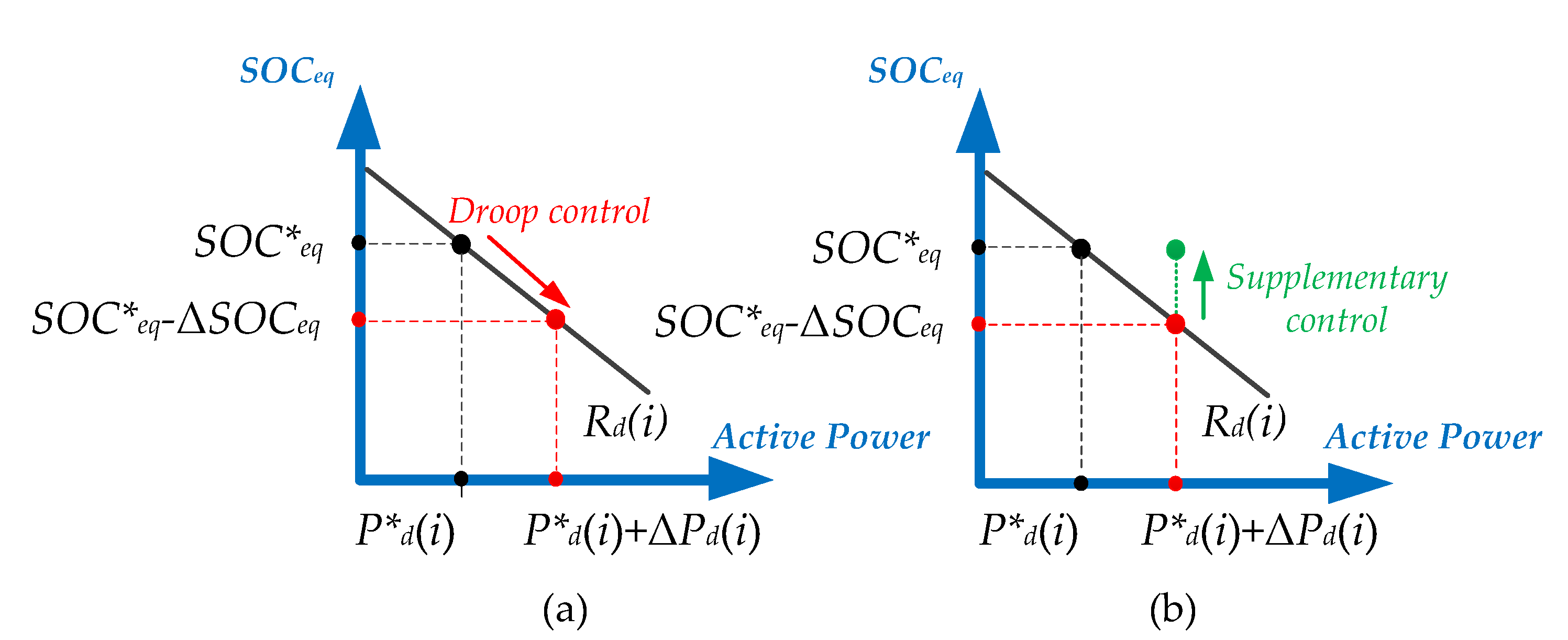
3.1. SOCeq Control Scheme for Single Diesel Generator

Firstly, we verify that SOCeq can be regulated by a single diesel generator in an isolated microgrid with multiple BESSs. By differentiating (1), we obtain
( k = 1 n C r a t e ( k ) V d c ( k ) ) d ( S O C e q ) d t = k = 1 n C r a t e ( k ) V d c ( k ) d ( S O C ( k ) ) d t .
From [13], the SOC of the k-th BESS can be expressed as follows:
S O C ( k ) = S O C 0 ( k ) P B E S S ( k ) V d c ( k ) C r a t e ( k ) d t ,
where SOC0(k) is the initial value of SOC and PBESS(k) is the active power of the k-th BESS. By taking the derivative of (3), we obtain
d S O C ( k ) d t = P B E S S ( k ) C r a t e ( k ) V d c ( k ) .
By substituting (4) into (2) and under the assumption that Vdc(k) is almost constant and equal to the rated value within the normal SOC region [7], the derivative of SOCeq can be expressed as follows:
d ( S O C e q ) d t = ( P B E S S ( 1 ) + + P B E S S ( n ) ) ( k = 1 n C r a t e ( k ) V d c , r a t e ( k ) ) .
To satisfy the power-balance equation of an isolated microgrid, the summation of the total active power outputs of the BESSs and diesel generator should be equal to the active power of net load.
P B E S S ( 1 ) + + P B E S S ( n ) + P d = P n e t , l o a d ,
where Pd is the active power output of the diesel generator and Pnet,load is the net load including the uncontrollable outputs of RESs, loads, and system losses.
For a single diesel generator, the isochronous control mode can be adopted for frequency regulation in a conventional power system [14,15]. Likewise, in the proposed method, a single diesel generator operates in the isochronous mode for SOCeq control. Figure 4 represents the proposed SOCeq control structure for a single diesel generator, including a corresponding plant model from (5) and (6). Since the plant model between the diesel output and SOCeq is a first-order system as shown in Figure 4, a proportional integral (PI) controller can be adopted for SOCeq control [16].

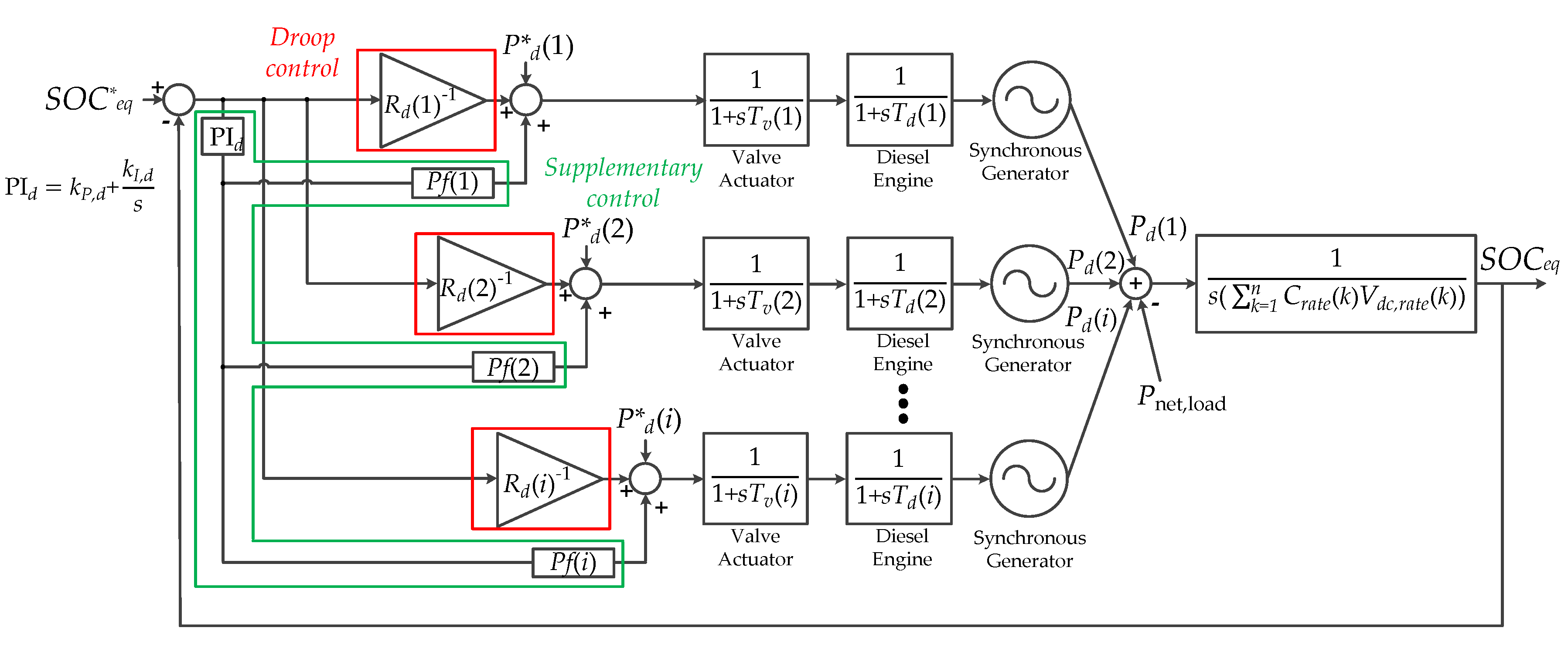
3.2. SOCeq Control Scheme for Multiple Diesel Generators

In a power system with multiple synchronous generators, a hierarchical frequency-control structure is utilized to prevent hunting effects on the frequency and inaccurate power sharing between generators at the steady-state [15]. Similarly, we propose a hierarchical control structure for multiple diesel generators to regulate SOCeq. Owing to the proposed hierarchical control, SOCeq can be regulated stably, and accurate power sharing between diesel generators at the steady-state is possible. Figure 5 shows the concept of the proposed hierarchical control structure for multiple diesel generators.
Firstly, we introduce the SOCeqP droop-control strategy for primary responses of SOCeq regulation and power sharing between diesel generators. As shown in Figure 5a, when an unexpected system variation occurs, SOCeq deviates from the reference value, SOC*eq. Based on the droop characteristic, the active power outputs of diesel generators increase (or decrease) from the reference value of the active power output of the i-th diesel generator, P*d(i). Eventually, SOCeq can be saturated at the point where the active power is balanced (red dot in Figure 5), and the BESSs make zero active power. The droop coefficient of the i-th diesel generator can be defined based on the slope in Figure 5a and represented by Rd(i) (i = 1, 2, and 3 for the target network).
Owing to the innate characteristics of the droop controller, steady-state error exists between the saturated value and the target reference value, ΔSOCeq. To restore SOCeq to its corresponding reference SOC*eq, supplementary control for secondary responses is provided as shown in Figure 5b. By integrating the concepts of the droop controller in Figure 5a and the supplementary controller in Figure 5b, we develop the proposed hierarchical control structure including the plant model between the active power of diesel generators and SOCeq, as shown in Figure 6, where Pf(i) is the participation factor, Tv(i) is the time constant of the valve actuator, and Td(i) is the time constant of the diesel engine for the i-th diesel generator. The supplementary controllers are implemented with a PI controller for eliminating the steady-state error and participation factor for determining the sharing ratio. Similar to the conventional load frequency control structure, the supplementary controller must be operated to respond slower than the droop controllers [15] in diesel generators.

4. Control Strategy of Battery Energy Storage Systems (BESSs)

4.1. Frequency Control Scheme for Multiple BESSs

When a single BESS controls the frequency of the system, a converter is operated in the grid-forming mode to control the frequency directly. The detailed scheme of the grid-forming mode is shown in [16,17]. To regulate the grid frequency when using multiple BESSs with grid-forming converters, hierarchical control for frequency regulation can be utilized [18,19]. For the primary response, the P-f droop control method is adopted for the parallel operation of BESSs, as shown in Figure 7a. Additionally, for secondary response, as shown in Figure 7b, a supplementary controller including an integrator is exploited to eliminate the steady-state error of frequency generated from droop control.
In Figure 7, f0 is the nominal frequency, P*BESS(k) is the reference active power, and Rb(k) is the droop constant of k-th BESS.

4.2. Self State of Charge (SOC) Controller for Individual BESSs

Frequency can be regulated almost perfectly by utilizing BESSs, and SOCeq can be maintained at the desired reference value with diesel generators. However, the management of individual SOCs cannot be guaranteed by exploiting the controllers presented in the previous sections, because only the total energy of BESSs is considered in diesel generators. In addition, from the integral of supplementary frequency controllers, the power sharing between BESSs is not guaranteed from the desired value [18,19]. Therefore, the individual SOCs of BESSs should be controlled at their reference values by themselves with an additional controller. To regulate the individual SOCs of BESSs at the reference values, we develop SSC for restoring the individual SOCs. Since the BESSs are operated by grid-forming converters, which control the frequency of their terminals, BESSs should regulate their SOCs by adjusting their terminal frequencies. To validate the necessity of SSC, a simplified circuit for BESSs, as shown in Figure 8, is first investigated.
In Figure 8, X(k) is the reactance component of the transformer, ∠θ(k) and |V(k)| are the phase angle and magnitude of ac voltage at the terminal node of the k-th BESS, and ∠θbus(k) and |Vbus(k)| are the phase angle and magnitude of ac voltage at the bus connected to the k-th BESS. As reactance is much larger than the resistance in the transformer [20], the transformer is modeled by a single reactance. From Figure 8, the active power output of the k-th BESS can be approximated as follows [21]:
P B E S S ( k ) = | V ( k ) | | V b u s ( k ) | ( θ ( k ) θ b u s ( k ) ) X ( k ) .
From (4) and (7), the SOC of the k-th BESS can be expressed as follows:
d S O C ( k ) d t = 1 C r a t e ( k ) V d c , r a t e ( k ) | V ( k ) | | V b u s ( k ) | ( θ ( k ) θ b u s ( k ) ) X ( k ) ,
with the assumption that the entire system except the k-th BESS is constant, the derivative of the phase angle for bus k is zero. By differentiating (8), we can obtain:
d 2 S O C ( k ) d t 2 = 2 π | V ( k ) | | V b u s ( k ) | C r a t e ( k ) V d c , r a t e ( k ) X ( k ) f ( k ) ,
where f(k) is the frequency output of the k-th BESS. As the plant model between the frequency and SOC of the k-th BESS is a second-order system, each BESS can regulate its SOC by itself with a PI controller [16].
The purpose of SSC is to restore the SOC of the k-th BESS to its corresponding reference value, SOC*(k). However, as diesel generators respond slowly compared to BESSs, the transient difference between SOCeq and its reference value, SOC*eq, should be considered in SSC. Therefore, in SSC, the reference value for the SOC of the k-th BESS must be modified as follows:
S O C r e f ( k ) = S O C * ( k ) + S O C e q S O C e q * .
where SOCref(k) is the adjusted reference value of SOC(k) considering the transient state. Note that SOCref(k) and SOC*(k) eventually become equal in the steady state because SOCeq is regulated to SOC*eq by diesel generators in the long time scale. Figure 9 shows the total control structure of the k-th BESS including inner control loops [14,17], the hierarchical frequency controller, and SSC.
In Figure 9, I(k) is the line current from the kth BESS, V(k) is the terminal voltage, Iout(k) is the line current to the terminal node, L(k) and Cf(k) are the filter components, θ*(k) is the reference phase angle for the modified reference frequency value, and u(k) is the modulating signal of the k-th BESS. Superscripts d and q indicate the dq components of corresponding variables.
The reference frequency value and θ*(k) are determined from the hierarchical frequency controller and SSC. The dq components of the reference voltage are derived from the reference value of voltage magnitude, Vd*(k), and θ*(k). Finally, the terminal voltage of the k-th BESS is regulated to the reference value via a nested voltage and current control loop, as shown in Figure 9. Through the entire control loop, the frequency and SOC of each BESS are regulated.

4.3. Maintaining Desired Active Power Outputs of BESSs by the Linear Time-Varying SOC Control

By regulating SOCs as the linear time varying value, the BESSs can be controlled as the desired level of active power outputs [7]. In other words, while BESSs control frequency, they can maintain the scheduled or dispatched active power. From integrating (4), to make the active power of k-th BESS as the reference value P*BESS(k), SOC reference value can be determined as:
S O C * ( k ) = P * B E S S ( k ) C r a t e ( k ) V d c ( k ) d t ,
As P*BESS(k) is desired constant value, SOC reference has the linear time varying value from (11). Through controlling SOCs as the linear time varying reference values as (11), BESSs can maintain the desired active power outputs.

5. Case Study

The isolated microgrid shown in Figure 2 was modeled and simulated by Simulink/MATLAB for the case study. All converters for RESs and BESSs in the system consisted of two-level half-bridge (HB) converters with switch models. Sine-pulse width modulation (SPWM) with switching frequency of 2 kHz was adopted to generate gate signals of switch model converters. The PV generator model consisted of photovoltaic source and converter [22]. The PV converter was controlled by the MPPT algorithm and inner dc voltage and current control loop. For MPPT, the perturbation and observation (P&O) algorithm in [23] was utilized and reference value of dc voltage was determined. To control the dc voltage of photovoltaic source as the reference value, the nested dc voltage and current control loops in [17] were used. On the other hand, the wind generator consisted of a permanent magnetic synchronous generator (PMSG), wind turbine, machine side converter, and grid side converter [22]. We utilized a permanent magnet synchronous generator model provided by Simulink/MATLAB. Wind turbine and controllers of the machine and grid side converters were modelled by the same procedure of [17]. The detailed parameters of the diesel generators and BESSs are listed in Table 2 and Table 3. For voltage control, conventional reactive power (Q)—magnitude of the ac voltage (Vac) droop method was adopted in diesel generators and BESSs [24]. Q–Vac droop constants for three diesel generators were 0.05/20 (Vp.u./kVar) respectively and Q–Vac droop constant for BESS 1 was 0.05/250 (Vp.u./kVar) and for BESS 2 was 0.05/125 (Vp.u./kVar). As the reactive power and magnitude of ac voltage were not the major concern of this paper, we just adopted the conventional method in [24].
The capacity of BESSs was scaled down from its real values, 500 and 300 kWh, by a factor of 1/100 in the simulation to illustrate the variation of SOCs clearly. The supplementary controllers of diesel generators have a sample time of 0.5 s to ensure slower response compared to the droop controller. Other components including transformers, lines, and loads were modeled with the parameters shown in Figure 2. Considering the fact that the efficiency of batteries is dependent on SOC level [25,26], we assumed that BESS 1 and 2 have the highest efficiency at 60% and 40% of SOCs, respectively.

5.1. Case 1: Step Load Change with the Conventional and Proposed Control Method

In Case 1, to verify the effectiveness of the proposed strategy, the proposed method was compared to the CD method for the step load change. As CD method can be adopted in the system with multiple diesel generators and BESSs, has been widely adopted in many researches [27,28], and was the original control method in Geocha Island, we selected CD method for comparison. Before 10 s, all loads except the load at bus 7 were connected. After 10 s, the load at bus 7 was connected to the system. The active power consumption for loads was constant, as shown in Figure 2. The active power generated by the PV and wind generators was constant at 80 and 75 kW respectively. SOC reference values for BESS 1 and 2 were 60% and 40%, respectively.
Figure 10 shows the responses of frequency and SOCeq in the conventional and proposed methods. As shown in Figure 10a, the frequency eventually maintains its rated value irrespective of the control method. However, while the conventional control method takes approximately 20 s to restore frequency, the proposed control takes less than 2 s, as shown in Figure 10a. BESSs are exploited for frequency restoration in the proposed scheme, while diesel generators are used for the conventional method. For this reason, the performance of frequency regulation is much better in the proposed method than the conventional method. Furthermore, as shown in Figure 10b, SOCeq can be constant in both methods because long-time-scale energy imbalances are compensated for by diesel generators. However, as SOC management is not considered in the conventional method, SOCeq deviates from the reference value. On the other hand, SOCeq is regulated at the reference value by using the proposed strategy. This implies that BESSs with a relatively small capacity are required with the proposed method.
Figure 11 shows the active power of diesel generators and BESSs in the conventional and proposed methods. In both methods, diesel generators share the load equally at the desired power-sharing ratio, as shown in Figure 11a, and BESSs make zero output equally as desired, as shown in Figure 11b. In the proposed method, parallel operation and power sharing of diesel generators and BESSs are possible, as desired.

5.2. Case 2: Step Load Change with and without Self SOC Controller (SSC)

In Case 2, the loads, PV generation, and wind generation are the same as in Case 1. To verify the necessity of SSC, the responses of BESSs with and without SSC were compared. SOC reference values for BESS 1 and 2 were 60% and 40%, respectively. Figure 12 shows the frequency and SOCeq with and without SSC. In both cases, the responses of the frequency and SOCeq are almost identical, which implies that, except for the individual SOCs of BESSs, the SSC hardly affects the performance of the system.
Figure 13 shows the individual SOCs of BESSs in the proposed control with and without SSC. Although SOCeq is regulated at the reference value irrespective of whether SSC is applied, the SOC of each BESS in the proposed control with and without SSC has different responses. In the case without SSC, the SOC of each BESS deviates from its corresponding reference value. This phenomenon is similar to the occurrence of a circulating current, in which summation is equal to the desired value but individual components have different sign [29]. In the proposed control with SSC, the SOC of each BESS can be restored to its reference value. Thus, SSC is necessary to maintain the individual SOCs of BESSs. Furthermore, as SOCs of BESS 1 and 2 are maintained as 60% and 40% respectively, we can utilize BESSs at their highest efficient points with SSC.

5.3. Case 3: Fluctuation of Renewable Energy Sources (RESs) with the Conventional and Proposed Control Method

In Case 3, to verify the robustness of the system with the proposed control, fluctuations of the outputs of RESs were simulated when applying the proposed and conventional CD methods. The loads were constant, as shown in Figure 2. SOC reference values for BESS 1 and 2 were 60% and 40%, respectively. PV generation and wind generation were varied, as shown in Figure 14.
Figure 15 shows the frequency and SOCeq. As shown in Figure 15a, the frequency is fluctuated by the intermittent outputs of RESs with the conventional method. However, with the proposed method, the frequency is near the nominal value and can be controlled quickly. In addition, as shown in Figure 15b, while SOCeq deviates from the reference value with the conventional method, the proposed method maintains SOCeq near the reference value with a small fluctuation, which was due to the slow response of diesel generators. These results imply that the proposed method can make the system robust and improve its reliability, even with a high penetration of RESs.
Figure 16 shows the individual SOCs of BESSs. As shown in Figure 16, while the SOC of each BESS deviates from the reference value in the conventional method, the SOC of each BESS is near the reference value in the proposed method, similar to SOCeq in Figure 15b. Thus, the proposed method can manage not only SOCeq but also the SOC of each BESS. Even if a large power fluctuation occurred in the system, the individual SOCs of BESSs can be maintained and bounded tightly. This implies that batteries with a relatively small capacity are required, even with a high penetration of RESs, when the proposed method is adopted.

5.4. Case 4: Consideration of Communication Delays

In Case 4, we verify the performance of the proposed method when communication delays are considered. When diesel generators control SOCeq and SSCs of BESSs are operated, the information of SOCeq is required. Because capacities of BESSs are constant, only simple communication lines for transmitting information of SOCs are required. In the case of Geocha Island microgrid, diesel generators and BESSs are located in the same station as shown in Figure 3. For this reason, communication delay can be ignored in Geocha Island microgrid. However, to adopt the proposed control method in other islanded microgrids where BESSs and diesel generators are far away from each other, we have to verify the performance of the proposed method when communication delays exist. The communication delays range from several milliseconds to about 100 ms in the wide area measurement/monitoring system for the large scale power system [30], hence, communication delays in islanded microgrids may be smaller than 100 ms. To verify the possibility for application of the proposed method, we tested the system when communication delays were 0, 50, and 100 ms. All other conditions are the same as Case 1. Figure 17 shows frequency and SOCeq of the proposed method with 0, 50, and 100 ms delay when load change occurred at 10 s.
As shown in Figure 17, if communication delays are prolonged, saturation time of frequency and SOCeq takes a little longer. However, regardless of communication delays, frequency and SOCeq are eventually saturated. To ensure that individual SOCs of BESSs can be controlled even with communication delays, Figure 18 shows individual SOCs of BESSs.
As shown in Figure 18, if communication delays are prolonged, SOCs of BESSs are a little more slowly saturated. But, SOCs of BESSs can be regulated as the reference values regardless of communication delays. Therefore, the proposed method can be implemented in other islanded microgrids where communication delays should be considered.

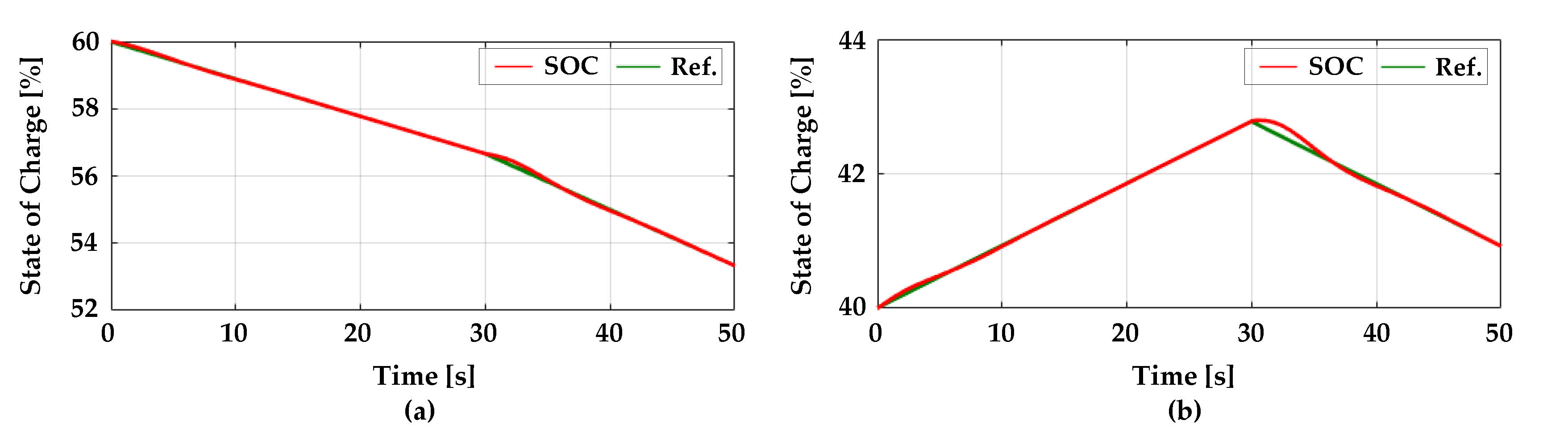
5.5. Case 5: Regulating Active Power of BESSs by the Linear Time-Varying Control of SOCs

In Case 5, to verify that the active power outputs of BESSs can be controlled as the desired values, we provided continuous responses of BESSs and diesel generators for linear time-varying control of SOCs of which reference values were determined by the active power references. All loads and wind and PV generation are the same as Case 1. Before 30 s, active power references, P*BESS(1) and P*BESS(2) were 20 and −10 kW (negative sign means that BESS was charged), respectively. After 30 s, P*BESS(1) and P*BESS(2) were 30 and 10 kW. According to determining active power references, SOC reference values were decided as shown in (11). Figure 19 shows SOCs and SOC reference values of BESSs.
As shown in Figure 19, by the active power reference values, the linear time-varying SOC reference values are determined. The slopes of SOC reference values are varied when the active power references are changed. Regardless of the slopes of SOC reference values, the SOCs of BESSs can be controlled as the reference values. To verify that frequency and active power outputs of BESS are controlled, Figure 20 shows the frequency and active power outputs of BESSs.
Frequency can be regulated as the nominal value, as shown in Figure 20a. Although the active power references of BESSs are changed, frequency maintains the nominal value with just small fluctuation. As described in Figure 20b, active power outputs of BESSs are near the reference values. Case 5 implies that by adopting the proposed control method, frequency and active power outputs of BESSs can be controlled simultaneously as the desired values.

6. Conclusions and Future Work

This paper proposed a coordinated frequency and SOC control method for implementing isolated microgrids having a high penetration of RESs with multiple diesel generators and BESSs. The stored energy of all BESSs can be managed with the hierarchical controllers in diesel generators. In addition, frequency can be controlled quickly and individual SOCs of BESSs can be managed at their reference values with the hierarchical controllers and SSCs in BESSs. From Case Study, we validated that the proposed method can give a chance to (1) lower the requirement for the capacity of batteries, (2) utilize BESSs at their highest efficiency, (3) maintain the active power of BESSs for scheduled or dispatched values, and (4) operate the system robustly even with large fluctuation of RESs.
One of the future works is the magnitude of ac voltage and reactive power control. If effective voltage/reactive power control method is coordinated with our proposed method, more stable and efficient operation of islanded microgrids will be implemented.

Author Contributions

J.-W.C. organized the manuscript and wrote the manuscript; G.-S.L. conceived the main idea; H.-J.M. performed the simulations; M.B.G. gave some useful information for the manuscript; S.-I.M. provided the overall guidance for the manuscript.

Funding

This research received no external funding.

Acknowledgments

This work was supported by the Korea Institute of Energy Technology Evaluation and Planning (KETEP) and the Ministry of Trade, Industry and Energy (MOTIE) of the Republic of Korea (No. 20188550000410).

Conflicts of Interest

The authors declare no conflict of interest.

References

  1. Pashajavid, E.; Ghosh, A. Frequency support for remote microgrid systems with intermittent distributed energy resources—A two-level hierarchical strategy. IEEE Syst. J. 2014, 12, 2760–2771. [Google Scholar] [CrossRef]
  2. Mohamed, S.; Shaaban, M.F.; Ismail, M.; Serpedin, E.; Qaraqe, K. An efficient planning algorithm for hybrid remote microgrids. IEEE Trans. Sustain. Energy 2018, 10, 257–267. [Google Scholar] [CrossRef]
  3. Etxegarai, A.; Equia, P.; Torres, E.; Iturregi, A.; Valverde, V. Review of grid connection requirements for generation assets in weak power grids. Renew. Sustain. Energy Rev. 2015, 41, 1501–1514. [Google Scholar] [CrossRef]
  4. Kim, Y.S.; Hwang, C.S.; Kim, E.S.; Cho, C. State of charge based active power sharing method in a standalone microgrid with high penetration level of renewable energy sources. Energies 2016, 9, 480. [Google Scholar] [CrossRef]
  5. Liu, Y.; Du, W.; Xiao, L.; Wang, H.; Cao, J. A method for sizing energy storage system to increase wind penetration as limited by grid frequency deviations. IEEE Trans. Power Syst. 2016, 31, 729–737. [Google Scholar] [CrossRef]
  6. Diaz, N.L.; Luna, A.C.; Vasquez, J.C.; Guerrero, J.M. Centralized control architecture for coordination of distributed renewable generation and energy storage in islanded ac microgrids. IEEE Trans. Power Electron. 2017, 32, 5202–5213. [Google Scholar] [CrossRef]
  7. Kim, Y.S.; Kim, E.S.; Moon, S.I. Frequency and voltage control strategy of standalone microgrids with high penetration of intermittent renewable generation systems. IEEE Trans. Power Syst. 2016, 31, 718–728. [Google Scholar] [CrossRef]
  8. Delille, G.D.; Francois, B.; Malarange, G. Dynamic frequency control support by energy storage to reduce the impact of wind and solar generation on isolated power system’s inertia. IEEE Trans. Sustain. Energy 2012, 3, 931–939. [Google Scholar] [CrossRef]
  9. Jiang, Q.; Hong, H. Wavelet-based capacity configuration and coordinated control of hybrid energy storage system for smoothing out wind power fluctuations. IEEE Trans. Power Syst. 2013, 28, 1363–1372. [Google Scholar] [CrossRef]
  10. Xiao, J.; Bai, L.; Li, F.; Liang, H.; Wang, C. Sizing of energy storage and diesel generators in an isolated microgrid using discrete fourier transform (DFT). IEEE Trans. Sustain. Energy 2014, 5, 907–916. [Google Scholar] [CrossRef]
  11. Singh, B.; Solanki, J. Compensation for diesel generator-based isolated generation system employing DSTATCOM. IEEE Trans. Ind. Appl. 2011, 5, 907–916. [Google Scholar] [CrossRef]
  12. Moon, H.J.; Kim, Y.J.; Chang, J.W.; Moon, S.I. Decentralised active power control strategy for real-time power balance in an isolated microgrid with an energy storage system and diesel generators. Energies 2019, 12, 511. [Google Scholar] [CrossRef]
  13. Gao, L.; Liu, S.; Dougal, R.A. Dynamic lithium-ion battery model for system simulation. IEEE Trans. Compon. Packag. Technol. 2002, 25, 495–505. [Google Scholar]
  14. Rocabert, J.R.; Luna, A.L.; Blaabjerg, F.; Rodriquez, P. Control of power converters in ac microgrids. IEEE Trans. Power Electron. 2012, 27, 4734–4749. [Google Scholar] [CrossRef]
  15. Kundur, P. Power System Stability and Control; McGraw-Hill: New York, NY, USA, 1994. [Google Scholar]
  16. Ogata, K. Modern Control Engineering; Prentice Hall: Upper Saddle River, NJ, USA, 2009. [Google Scholar]
  17. Yazdami, A.; Iravani, R. Voltage-Sourced Converters in Power System; Willy Press: Hoboken, NY, USA, 2010. [Google Scholar]
  18. Kim, Y.S.; Kim, E.S.; Moon, S.I. Distributed generation control method for active power sharing and self-frequency recovery in an islanded microgrid. IEEE Trans. Power Syst. 2017, 32, 544–551. [Google Scholar] [CrossRef]
  19. Kosari, M.; Hosseinian, S.H. Decentralized reactive power sharing and frequency restoration in islanded microgrid. IEEE Trans. Power Syst. 2017, 32, 2901–2912. [Google Scholar] [CrossRef]
  20. IEEE. IEEE Recommended Practice for Protection and Coordination of Industrial and Commercial Power Systems; IEEE: Piscataway, NJ, USA, 1986. [Google Scholar]
  21. Bergen, A.R. Power System Analysis; Prentice-Hall: Englewood Cliffs, NJ, USA, 1986. [Google Scholar]
  22. Teodorescu, R.; Liserre, M.; Rodriguez, P. Grid Converters for Photovoltaic and Wind Power Systems; John Wiley & Sons: Chichester, UK, 2011. [Google Scholar]
  23. Femia, N.; Petrone, G.; Spagnuolo, G.; Vitelli, M. Optimization of perturb and observe maximum power point tracking method. IEEE Trans. Power Electr. 2005, 20, 963–973. [Google Scholar] [CrossRef] [Green Version]
  24. Paquette, A.D.; Reno, M.J.; Harley, R.G.; Divan, D.M. Sharing transient loads: Causes of unequal transient load sharing in islanded microgrid operation. IEEE Ind. Appl. Mag. 2014, 20, 22–34. [Google Scholar] [CrossRef]
  25. Badin, F.; Le Berr, F.; Briki, H.; Dabadie, J.-C.; Petit, M.; Magand, S.; Condemine, E. Evaluation of EVs energy consumption influencing factors, driving conditions, auxiliaries use, driver’s aggressiveness. In Proceedings of the 2013 World Electric Vehicle Symposium and Exhibition (EVS27), Barcelona, Spain, 17–20 November 2013; pp. 1–12. [Google Scholar]
  26. Ng, K.S.; Moo, C.S.; Chen, Y.P.; Hsieh, Y.C. Enhanced coulomb counting method for estimating state-of-charge and state-of-health of lithium-ion batteries. Appl. Energy 2009, 86, 1506–1511. [Google Scholar] [CrossRef]
  27. Delille, G.; Francois, B.; Malarange, G. Dynamic frequency control support: A virtual inertia provided by distributed energy storage to isolated power systems. In Proceedings of the IEEE Innovative Smart Grid Technologies Europe Conference (ISGT), Gothenburg, Sweden, 11–13 October 2010. [Google Scholar]
  28. Wang, Y.; Delille, G.; Guillaud, X.; Colas, F.; Francois, B. Real-time simulation: The missing link in the design process of advanced grid equipment. In Proceedings of the IEEE PES General Meeting, Minneapolis, MN, USA, 25–29 July 2010. [Google Scholar]
  29. Pan, C.T.; Liao, Y.H. Modeling and coordinate control of circulating currents in parallel three-phase boost rectifiers. IEEE Trans. Ind. Appl. 2007, 54, 825–838. [Google Scholar] [CrossRef]
  30. Xie, X.; Xin, Y.; Xiao, J.; Wu, J.; Han, Y. WAMS application in Chinese power system. IEEE Power Energy Mag. 2006, 4, 54–63. [Google Scholar]
Figure 1. Complementary control methods with diesel generator and battery energy storage system (BESS) for system imbalance: (a) coordinated droop control (CD); (b) control based on frequency distribution techniques (FD); (c) coordinated state of charge (SOC) and frequency control (CSF).
Energies 12 01614 g001
Figure 2. System configuration of the Geocha Island microgrid.
Energies 12 01614 g002
Figure 3. Proposed control strategy for the Geocha Island microgrid.
Energies 12 01614 g003
Figure 4. Plant model of the isochronous mode of the diesel generator.
Energies 12 01614 g004
Figure 5. Hierarchical SOCeq control of diesel generators: (a) droop; (b) supplementary control.
Energies 12 01614 g005
Figure 6. Plant model for the hierarchical control scheme of multiple diesel generators.
Energies 12 01614 g006
Figure 7. Hierarchical frequency control of BESSs. (a) Droop and (b) supplementary control.
Energies 12 01614 g007
Figure 8. Simplified single line diagram between a terminal node and the main bus of the k-th BESS.
Energies 12 01614 g008
Figure 9. Proposed controller of BESS for frequency and self state of charge (SOC) recovery.
Energies 12 01614 g009
Figure 10. Frequency and SOCeq in the conventional and proposed methods: (a) frequency; (b) SOCeq.
Energies 12 01614 g010
Figure 11. Active power in the conventional and proposed methods: (a) diesel generators; (b) BESSs.
Energies 12 01614 g011
Figure 12. Frequency and SOCeq of BESSs in Case 2: (a) frequency; (b) SOCeq.
Energies 12 01614 g012
Figure 13. SOC of each BESS in Case 2: (a) BESS 1; (b) BESS 2.
Energies 12 01614 g013
Figure 14. Variation of the active power of photovoltaic (PV) and wind generation in Case 3: (a) PV; (b) wind.
Energies 12 01614 g014
Figure 15. Frequency and SOCeq in Case 3: (a) frequency; (b) SOCeq.
Energies 12 01614 g015
Figure 16. SOC of each BESS in Case 3: (a) BESS 1; (b) BESS 2.
Energies 12 01614 g016
Figure 17. Frequency and SOCeq in Case 4: (a) frequency; (b) SOCeq.
Energies 12 01614 g017
Figure 18. SOC of each BESS in Case 4: (a) BESS 1; (b) BESS 2.
Energies 12 01614 g018
Figure 19. SOCs and SOC reference values of BESSs in Case 5: (a) BESS1; (b) BESS2.
Energies 12 01614 g019
Figure 20. Frequency and active power outputs of BESSs in Case 5: (a) frequency; (b) active power outputs of BESSs.
Energies 12 01614 g020
Table 1. Comparison between conventional and proposed CSF methods.
Control MethodParallel Operation of Diesel GeneratorsParallel Operation of BESSsFrequency ControlSOC Control
Conventional CSFXXO△ (Single)
Proposed CSFOOOO (Multiple)
Table 2. Control parameters in the conventional and proposed method.
Control MethodTypeParameterSymbolValue
Conventional MethodDiesel GeneratorsDroop gainRd(1), Rd(2), Rd(3)4.8/150 Hz/kW
PI gain for suppl. controlkP,sup(1) + kI,sup(1)/s, kP,sup(2) + kI,sup(2)/s60,000 + 45,000/s
Participation factorPf(1), Pf(2), Pf(3)1/3
BESSsDroop gainRb(1), Rb(2)0.6/250, 0.4/150 Hz/kW
Proposed MethodDiesel GeneratorsDroop gainRd(1), Rd(2), Rd(3)5/150%/kW
PI gain for suppl. controlkP,d + kI,d/s,30,000 + 22,500/s
Participation factorPf(1), Pf(2), Pf(3)1/3
BESSsDroop gainRb(1), Rb(2)0.6/250, 0.4/150 Hz/kW
PI gain for suppl. controlkP,s(1) + kI,s(1)/s, kP,s(2) + kI,s(2)/s0 + 500/s, 0 + 100/s
PI gain for self SOC controlkP,SSC(1) + kI,SSC(1)/s, kP,SSC(2) + kI,SSC(2)/s20 + 5/s
SOC reference valueSOCref(1), SOCref(2)60%, 40%
Table 3. Parameters of diesel generators and BESSs for the internal controllers.
TypeParameterSymbolValue
Diesel GeneratorsValve-actuator time constantTv(1), Tv(2), Tv(3)0.05 s
Diesel-engine time constantTd(1), Td(2), Td(3)0.5 s
BESSsFilter componentsLf(1), Lf(2), Cf(1), Cf(2)0.14 mH, 0.25 mH
4.8 mF, 3.4 mF
Voltage-control PI gainkP,v(1)+ kI,v(1)/s, kP,v(2)+ kI,v(2)/s3 + 500/s, 3 + 1000/s
Current-control PI gainkP,c(1) + kI,c(1)/s, kP,c(2)+ kI,c(2)/s32 + 300/s, 35 + 200/s
Rated battery capacityCrate(1), Crate(2)5000/710, 3000/650 Ah
Nominal battery voltageVdc,rate(1), Vdc,rate(2)710, 650 V
Initial SOCSOC0(1), SOC0(2)60%, 40%

