Article

Experimental Investigation of a Small-Scale ORC Power Plant Using a Positive Displacement Expander with and without a Regenerator

School of Engineering, University of Glasgow, Glasgow G12 8QQ, UK
*
Author to whom correspondence should be addressed.
The original paper was presented in: Collings, P.; Yu, Z.; Mckeown, A. “Experimental Analysis of a Regenerative Organic Rankine Cycle using Zeotropic Working Fluid Blends.” Riehl, R., Preißinger, M., Eames, I., Tierney, M., Eds. In Proceedings of the Heat Powered Cycles Conference 2018, Bayreuth, Germany, 16–19 September 2018; ISBN 978-0-9563329-6-7
Energies 2019, 12(8), 1452; https://doi.org/10.3390/en12081452
Submission received: 19 March 2019 / Revised: 11 April 2019 / Accepted: 14 April 2019 / Published: 16 April 2019
(This article belongs to the Special Issue Selected Papers from Heat Power Cycles Conference 2018)

Abstract

:
While large-scale ORC power plants are a relatively mature technology, their application to small-scale power plants (i.e., below 10 kW) still encounters some technical challenges. Positive displacement expanders are mostly used for such small-scale applications. However, their built-in expansion ratios are often smaller than the expansion ratio required for the maximum utilisation of heat sources, leading to under expansion and consequently higher enthalpy at the outlet of the expander, and ultimately resulting in a lower thermal efficiency. In order to overcome this issue, one possible solution is to introduce an internal heat exchanger (i.e., the so-called regenerator) to recover the enthalpy exiting the expander and use it to pre-heat the liquid working fluid before it enters the evaporator. In this paper, a small-scale experimental rig (with 1-kW rated power) was designed and built that is capable of switching between regenerative and non-regenerative modes, using R245fa as the working fluid. It has been tested under various operating conditions, and the results reveal that the regenerative heat exchanger can recover a considerable amount of heat when under expansion occurs, increasing the cycle efficiency.

1. Introduction

There is an ever-growing demand for power generation worldwide, while there are serious concerns about the impact of the emissions of carbon dioxide and other pollutants associated with the generation of this power. On the other hand, between 20–50% of the primary energy to industry is released to the environment in the form of waste heat [1,2], and a significant proportion of waste heat from industry (around 65% in the United Kingdom) is released at temperatures lower than 250 °C at relatively small scales [3].
Although there are several competing technologies for utilisation of the low-temperature heat sources mentioned, such as the Stirling cycle [4], reversed Brayton cycle [4], and the Kalina cycle [5], research has reported that the Organic Rankine Cycle (ORC) is the most promising technology for the utilisation of low-temperature heat sources, due to its simplicity and low operating pressures [4,6]. However, the application of the ORC technology to such low temperature heat sources at small scales still encounters some challenges, such as its low thermal efficiency and consequently low cost-effectiveness. Scardigno et al. [7] performed an optimisation of a dual waste heat/solar-driven ORC using a genetic algorithm, varying working fluid, evaporator pressures, condenser pressures, and the temperature of the thermal fluid exiting the solar collector. For a waste heat source temperature of 90 °C, the greatest efficiency and lowest levelised cost of electricity were given for cyclopropane, whereas the highest second-law efficiency was given by R143a. Ghasemian and Ehyaei [8] used several optimisation algorithms to maximise the thermal and exergy efficiencies of a cycle using a 180 °C heat source, and the cost of electricity production through varying the expander inlet temperature and pressure as well as the temperature differences in the heat exchangers. They found that the greatest performance was given by R11, with a thermal efficiency of 25.7% and an exergy efficiency of 57.3%.
Extensive research work has been conducted on ORC power plants at different scales, which achieved different thermal efficiencies. Prando et al. [9] achieved an efficiency of 17.2% using a biomass heat source temperature of 310 °C, a turbine expander, and MDM as the working fluid. Navarro-Esbrí et al. [10] achieved an efficiency of 14.6% using a combined solar and biomass heat source at 245 °C with R245fa as the working fluid. Peris et al. [11] reported an efficiency of 12.3% from a natural gas heat source at 156 °C using R245fa as the working fluid. Molés et al. [12] achieved an efficiency of 11.8% with an electric heat source at a temperature of 157 °C using R1233zdE. At the other end of the scale, Manolakos et al. achieved 1.03% efficiency using an open-drive scroll expander and R134a to harness a solar heat source at 76 °C [13]. Mikielewicz et al. [14] achieved an efficiency of 1.17% from an electric heat source at 160 °C using R123 and a pneumatic drill as the expansion device. Liu et al. [15] achieved an efficiency of 1.34% using a biomass heat source at 118 °C, a rotary vane expander, and HFE7000 as the working fluid.
For even lower temperature applications, Chang et al. [16] reported an efficiency of 7.5% from a heat source temperature of 92 °C using R245fa and a hermetic scroll expander. Yagoub et al. [17] achieved an efficiency of 7.6% from a heat source temperature of 70 °C using HFE7000 and a radial turbine expander. Tang et al. [18] achieved an efficiency of 7.5% from a heat source temperature of 100 °C using R123 and a twin-screw expander. Yang et al. [19] achieved an efficiency of 7.3% from a heat source temperature of 82 °C using R245fa and a radial turbine expander. From the thermodynamic viewpoint, as the heat source temperature drops, the thermal efficiency decreases significantly, leading to low cost-effectiveness. Therefore, it is important to develop methods to improve the system’s efficiency, especially when the heat source temperatures are relatively low.
Expanders are the heart of ORC power plants. Turbines are widely used for ORC power plants at large (MW) scales. However, their performances drop dramatically when they are scaled down to tens of kW. Positive displacement expanders are believed to be a better option [20] for such small-scale ORC power plants, which include scroll expanders, screw-vane type expanders, rotary-vane type expanders, and piston-type expanders [21]. Chang et al. compared various scroll expanders with different in-built volume ratios, investigating the effect of the pressure difference on isentropic and volumetric efficiency, and discovered that greater in-built volume ratios delivered higher performance under their experimental conditions. Yamada et al. [22] compared scroll-type and trochoidal-type expanders in a micro-ORC system with a power output of 10 W, finding a slightly greater efficiency for the trochoidal expander at this power level. Gao et al. compared different designs of scroll expander [23] to determine the effects of flow resistance and internal leakage on the isentropic efficiency of the expansion process.
Positive displacement devices present their own challenges. One of the key issues for developing small-scale ORC systems using positive displacement expanders is their small in-built expansion ratio, which is typically lower than four. Their resultant pressure ratios are normally less than that required to fully utilise the temperature difference between the heat source and heat sink, leading to under expansion. i.e., the high-pressure vapour entering the expander cannot fully expand to the condenser pressure within the expander. As a result, the temperature of the vapour exiting the expander is higher than it would otherwise have been in the case of perfect expansion. The thermal energy it carries normally is rejected to coolant within the condenser, causing low thermal efficiency. This issue is identified in the modelling of Liu et al. [24], wherein a non-regenerative cycle is shown to reach a plateau in thermal efficiency. One logical way to combat this is to use a regenerative heat exchanger to recover the thermal energy exiting from the expander, and use it to pre-heat the working fluid before it enters the evaporator. Regenerative ORCs have been considered in the past [22,24,25], but there is a lack of experimental research comparing the performance of the same cycle running in both regenerative and non-regenerative modes to demonstrate the benefits of such a regenerator in a small-scale ORC system using a positive displacement expander.
While the thermodynamic benefits of using a regenerator are well documented in the theoretical literature, the economic impact of its adoption has been less widely discussed. Algieri and Morrone [26] performed a techno-economic analysis of a biomass-fired cogenerating ORC, finding that a regenerative cycle using decane as the working fluid improved the electrical efficiency of the cycle significantly, which reduced the overall investment cost, which is an effect that increased at higher heat source temperatures. Conversely, a better heat source utilisation was given by a non-regenerative cycle operating with a degree of superheat. Amicabile et al. [27] found that while the use of a regenerator in a cycle using ethanol as the working fluid did increase the efficiency, it also increased the capital cost of the system. Wei et al. [28] compared regenerative and non-regenerative ORCs at heat source temperatures below 100 °C for waste heat recovery applications using three dry working fluids, and found that the improvement in thermal performance associated with the regenerative cycle did not offset an increased capital cost under these conditions, resulting in a higher levelised cost of energy and a longer payback period for the regenerative cycles. These reported analyses show that the efficacy of a regenerator in economic terms is highly dependent on the working fluid, heat source, and application of the cycle.
In this paper, a small-scale rig (rated at 1 kW) was built to isolate and investigate the effect of a regenerator on the performance of an organic Rankine cycle using a scroll-type positive displacement expander. Temperature and pressure were measured at various points in the cycle, as well as the power output, enabling the efficiency and pressure losses in the cycle to be examined and compared between the two cycle configurations across a range of heat source temperatures.

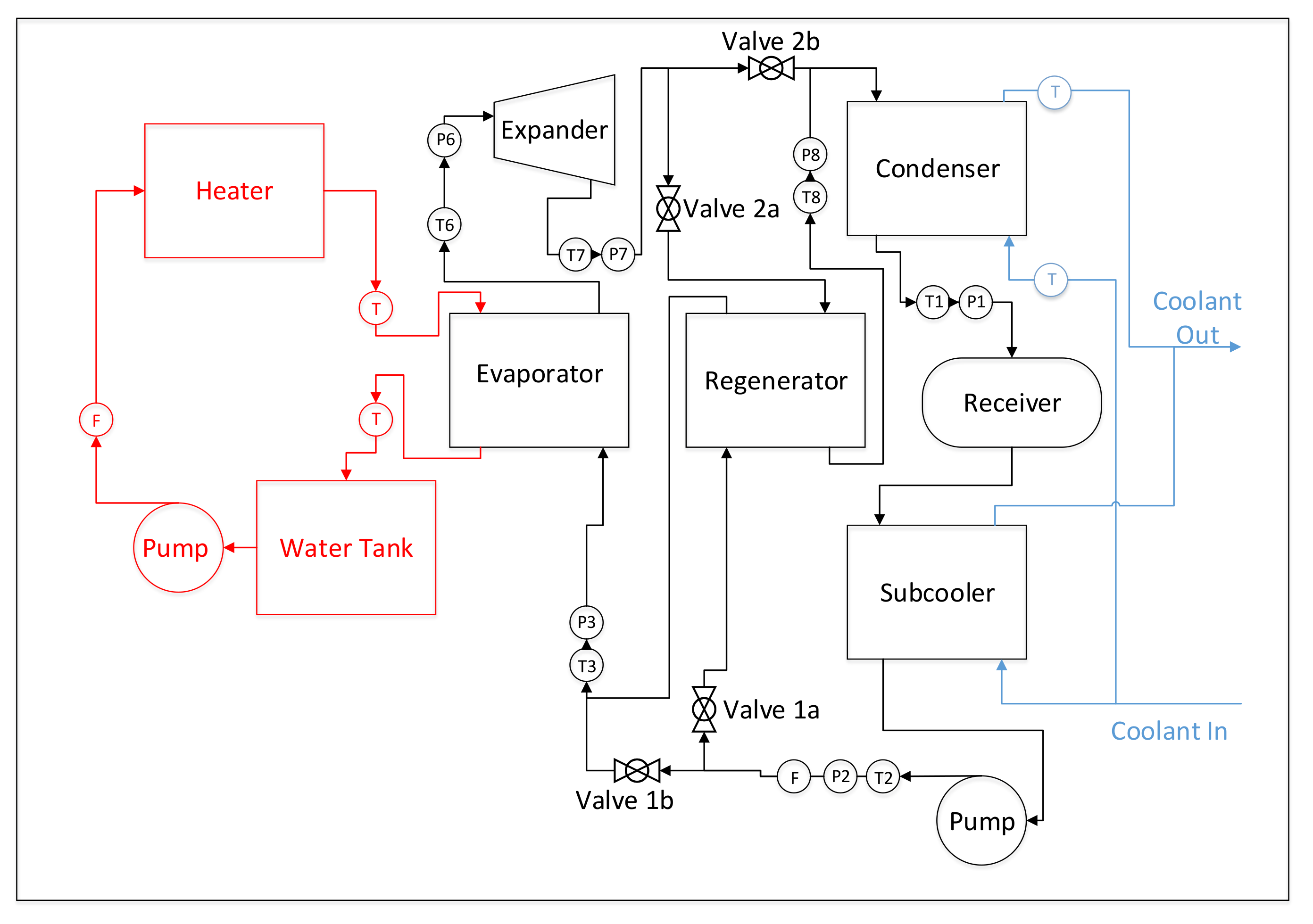
2. Experimental Set-Up

In order to experimentally compare the regenerative and non-regenerative ORC cycles, a small-scale (around 1 kW) experimental rig has been designed and constructed. Figure 1 shows a schematic diagram of the ORC rig, with the key components and instrumentation indicated.
There are several key features of the rig that should be noted. Firstly, the condenser has been elevated to the highest point of the rig, and a subcooler has been placed below the receiver, in order to ensure that the working fluid is a subcooled liquid with adequate net positive suction head (NPSH) before entering the pump, to avoid cavitation. Secondly, Valve Set 1 consists of two manually operated ball valves after the working fluid flow splits between the lines leading to the evaporator and regenerator. Closing Valve 1a leading to the regenerator and opening Valve 1b leading to the evaporator causes the working fluid to flow straight into the evaporator, bypassing the regenerator; closing Valve 1b and opening Valve 1a diverts the flow through the regenerator before rejoining the original flow path before the evaporator. Similarly, Valve Set 2 can be used to either divert the working fluid leaving the expander through the hot side of the regenerator by closing Valve 2b and opening Valve 2a, or let it flow directly to the condenser by closing Valve 2a and opening Valve 2b.
The expander selected for the system was an off-the-shelf E15H022A-SH from Airsquared, the details of which are given in Table 1. It has a nominal output of 1 kWe. It is a fully contained unit using a magnetic coupling to transfer power from the rotor of the expander to the generator, meaning no dynamic seals, which cuts out one significant leak path from the system. It has also been tested under a wide variety of inlet pressures and is known to be compatible with the refrigerant R245fa used in this research. Its ability to operate unlubricated due to using PTFE tip seals also removes a degree of complexity from the system and enables a fair comparison of cycle conditions without any extra variables introduced by the presence of lubricating oil in the working fluid. It has a peak isentropic efficiency for R245fa of 74%, according to manufacturer data [29].
The selection of working fluid was dictated by the choice of expander. The chosen expander has been tested by the manufacturer with R134a and R245fa. As the vapour pressure of R134a at room temperature is 4.86 bar, the volume ratio of the expander is 3.5, and the maximum inlet pressure is 13.8 bar; if the cycle were to use R134a as the working fluid, it would have to run permanently in under-expansion mode. Therefore, R245fa, which has a higher boiling point, and thus a lower vapour pressure, was chosen as the working fluid.
A diaphragm pump was chosen for the working fluid pump, as R245fa has material compatibility issues with several common sealant materials, and this design of pump separates the working fluid from the moving parts of the pump. A Hydra-Cell G20 pump, the details of which are given in Table 2, was chosen. The motor for the pump was driven by a frequency inverter powered by mains electricity, allowing the speed of the pump to be changed between 20 Hz and 60 Hz. As this type of pump is a positive displacement device, some amount of pulsation of the flow did occur; however, this did not seem to propagate to the expander, and the power output from the cycle was steady. However, there was a large amount of vibration in the pipework at certain pump speeds, which limited the testing to a small range of values. For future research, it is recommended that accumulators or vibration eliminators are used to mitigate this problem.
The four heat exchangers—vaporator, regenerator, condenser, and subcooler—were all identical Sondex SL-23 brazed plate heat exchangers. The details of the heat exchangers are given in Table 3.
The heater was a 27-kW electric immersion water heater. In the interests of safety, the water was not pressurised, limiting the maximum temperature in the cycle to 100 °C. Hot water was circulated using an off-the-shelf domestic central heating pump. The heat sink was provided by a vapour compression chiller with a capacity of 40 kW, and a set point of 7 °C. This avoided any possible effects on the cycle from varying ambient temperature.
For instrumentation, pressure and temperature were measured at six points in the system as shown in Figure 1, including the pump inlet, pump outlet, regenerator inlet, evaporator inlet, expander inlet, and condenser inlet. Temperature was measured using K-type probe thermocouples with a stated accuracy of ±0.2 °C; pressure was measured using PX-319 pressure transducers from Omega with a stated accuracy of ±0.25%. Enthalpy and entropy values could be calculated using REFPROP 9.1 [31]. The flow rate was measured using an FPD2002 flow meter, and the pump and generator powers were calculated using a digital power meter.

3. Definition of Parameters

While the instrumentation on the rig provided data on temperature, pressure, power input, power output, and flow rate, other thermal properties, such as enthalpy, entropy, density, and fluid quality had to be determined using REFPROP 9.1 [31]. With these properties known, several performance parameters of the system could be determined.
The heat input to the cycle was determined according to the equation:
Q ˙ i n = m ˙ w a t e r h w , i n h w , o u t
where m ˙ w a t e r is the flow rate of water through the hot side of the evaporator, and h w , i n and h w , o u t are the specific enthalpies of the water at the inlet and outlet of the evaporator, respectively, which were calculated using the temperature and pressure data from the rig’s iumentation.
The net power output of the cycle was calculated by subtracting the measured pump power from the measured power output from the alternator:
W ˙ n e t = W ˙ e x p a n d e r W ˙ p u m p
The measured efficiency was calculated by dividing the net power by the heat input:
η m e a s u r e d = W ˙ n e t Q i n ˙
The exergy at a given point i was given by:
B = h i h o T o s i s o
where the subscript o relates to the ground state, which in this case includes the fluid properties at atmospheric pressure and the temperature of the cooling water.
Some analysis of the heat exchangers was also carried. Pinch point diagrams could be constructed from the inlet and outlet conditions of the heat exchangers and the bubble and dew points, all of which were calculated using REFPROP from the data provided by the rig’s instrumentation. These methods are outlined in more detail in previous work by the authors [28].

4. Experimental Results

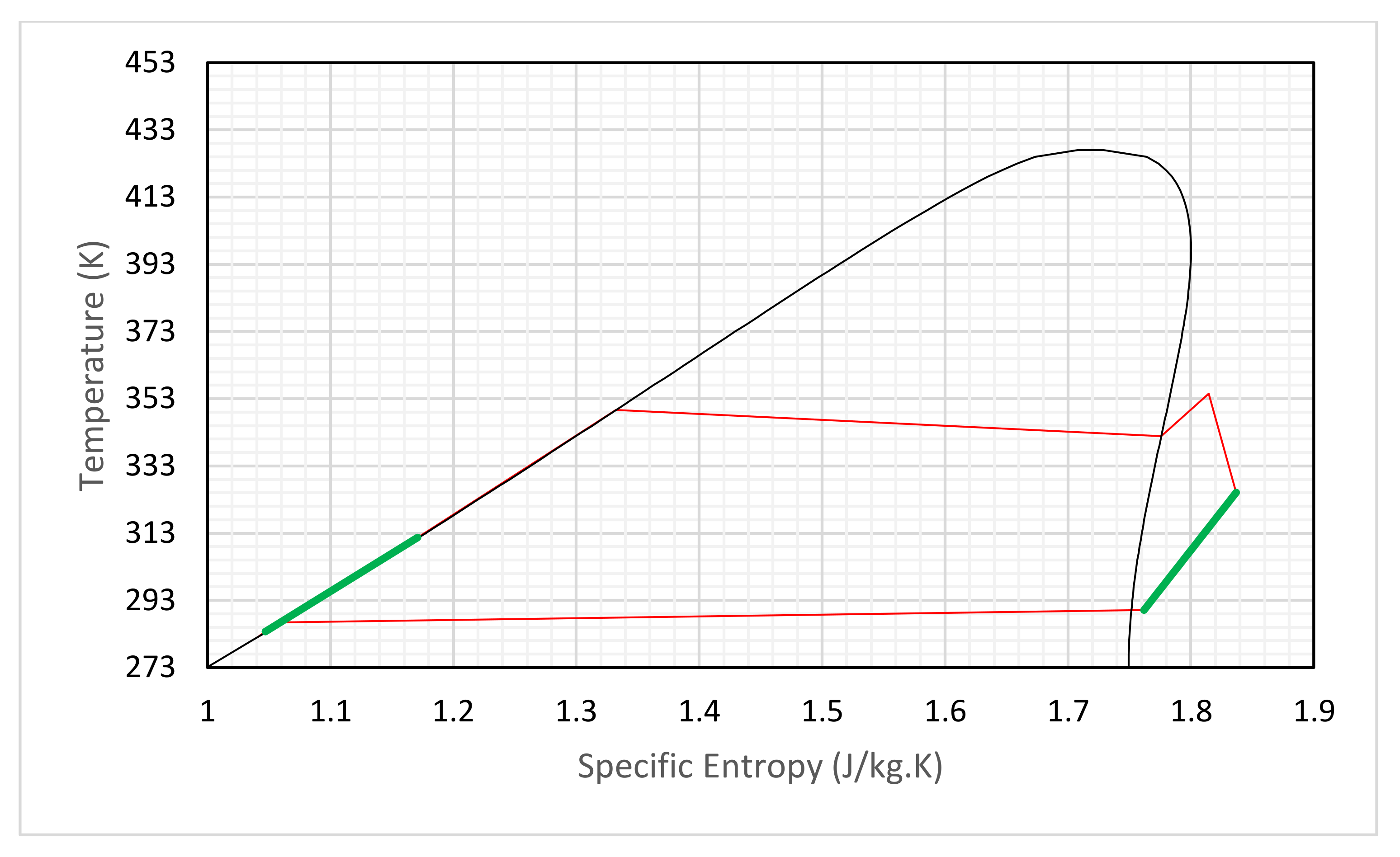
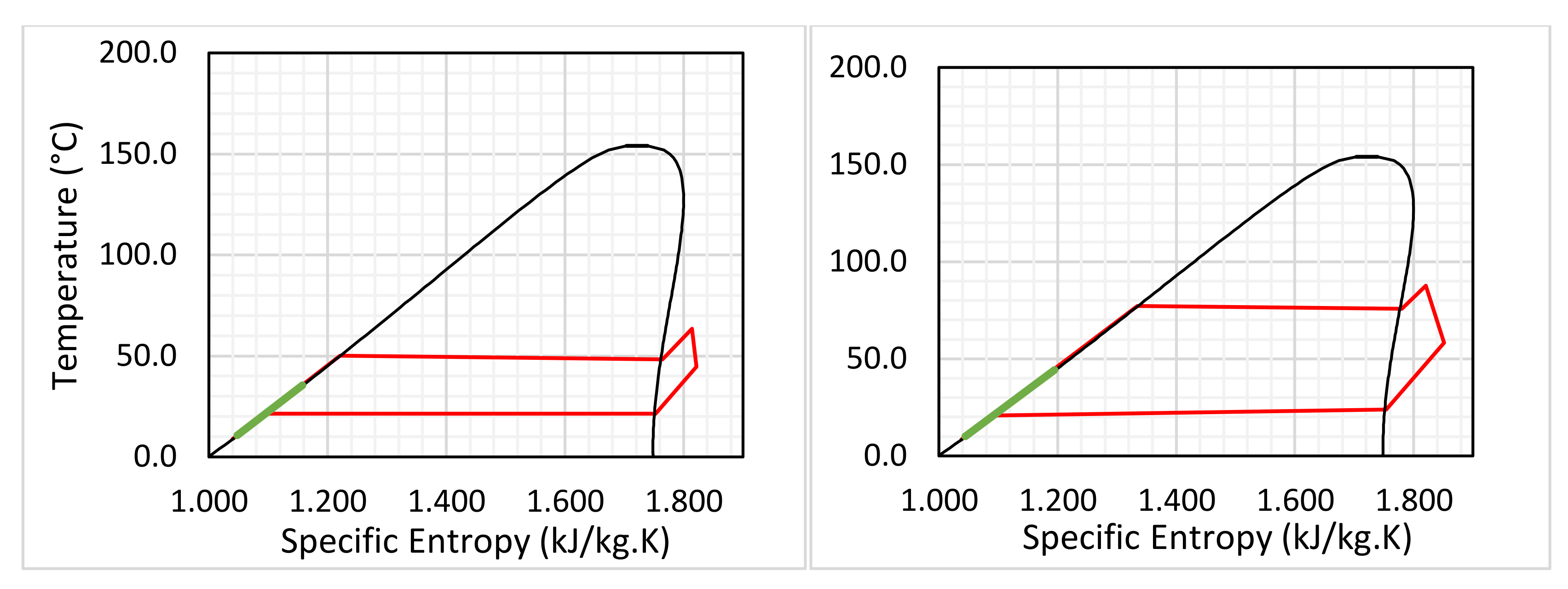
4.1. The Test Case with Highest Thermal Efficiency

Each test run consisted of running the rig for 30 min to ensure steady-state conditions. Once the rig had reached these conditions, the temperature, pressure, and flow rate data was averaged over a two-minute period to smooth out any transient effects.
The case with the highest thermal efficiency was achieved using a regenerative cycle with a heat source temperature of 90 °C. The results of the case with the maximum efficiency are given in Table 3, and also as a T-s diagram, as shown in Figure 2. Then, they are compared with the theoretical performance of a cycle calculated using the authors’ thermodynamic model [32] as shown in Figure 3. As shown in Table 3, the heat source and heat sink temperatures, the key control parameters, are respectively set as 90 °C and 7 °C in both experiments and simulations. The condensing pressure is determined by the condensing temperature and is measured as 1.4 bar in the experiments, and it was set at the same value in the simulations. In the experiments, the evaporating pressure was jointly determined by the speed of the liquid pump and the load to the generator. For this maximum efficiency case, the evaporation pressure was measured as 5.82 bar, and it was set as the value in the simulations. Then, the rest of the parameters were either measured directly as output in the experiments or deduced according to the measurements when the state properties of the refrigerant were needed.
As shown in Table 4, the hot water loop transferred around 3832 W of heating power to the evaporator, while the heat received by the refrigerant was deduced from its mass flow rate and temperatures at the inlet and outlet of the evaporator as 3617 W. Around 6% of the heat input was lost to the ambient air due to imperfect thermal insulation on the pipeline and evaporator. The generator produced around 352 W of electricity, which was consumed by four halogen bulbs. The power consumed by the liquid pump is 90 W, which was measured before the frequency inverter, so it accounts for the electrical losses of the frequency inverter. This was found not to vary with changes in the back pressure from the expander within the range considered in this work. The net power production is around 262 W, leading to a thermal efficiency of 6.8%.
For the simulations, the inlet pressure to the expander is set as the measured pressure of 5.82 bar. In comparison to the measurements, the predicted power generation by the generator is 315 W, which is slightly less than the measured result. This could be due to the value selected for isentropic efficiency, which was taken from the manufacturer’s datasheet. It could be that the field conditions experienced during the operation of the rig were different to the laboratory conditions under which the expander was originally tested, resulting in the isentropic efficiencies differing. It should be noted that the measured isentropic efficiency was deduced by the ratio of the power generation to the calculated isentropic enthalpy drop across the expander, where the enthalpies were deduced according to the measured temperatures and pressures at the inlet and outlet of the expander.
The calculated pump power of 16 W, which was calculated assuming an isentropic efficiency of 70%, is much less than the measured one of 90 W, which could be attributed to a lower isentropic efficiency of the pump in the experiments, due to for example, cavitation in the pump and electrical losses in the inverter and pump driving motor. As a result, the calculated net power production is 299 W. The heat input is estimated as 3660 W, which was calculated from the temperature drop in the heating water, and thus the calculated thermal efficiency is around 8.2%. The pressure ratio is around 4.16, which is higher than the ideal pressure ratio for the expander with an in-built volume ratio of 3.5 (calculated as 3.42, assuming an isentropic efficiency of 70%).
Figure 2 shows the T-s diagram of the highest efficiency case with the regenerative portion of the cycle highlighted in green. Figure 3 shows a comparison between the highest efficiency experimental case (i.e., a regenerative cycle arrangement) and the theoretical cycle predicted by the thermodynamic model [32]. Several things can be observed from this figure. Firstly, the pressure drops in the heat exchangers and pipework can be seen clearly. The working fluid in the theoretical case indicated by the blue line undergoes an isothermal and isobaric phase change in the condenser and evaporator. The working fluid in the experimental case undergoes a pressure drop as it passes from the pump outlet to the expander inlet through the evaporator and regenerator, resulting in a corresponding temperature drop, and increasing the amount of heat input. This is the reason for the disparity for the values of heat inputs seen in Table 4.
It can also be seen that an increase in the entropy during the expansion process for the experimental case is slightly smaller than in the theoretical case, indicating that the experimental case has a slightly higher isentropic efficiency (74%) than the theoretical case (70%), as shown in Table 3. The isentropic efficiency for the theoretical case is taken from the manufacturer’s performance curves. Without knowing the exact conditions under which the manufacturer’s tests were carried out, it is difficult to identify the cause of the discrepancy isentropic efficiency. This could also be attributed to the uncertainty of measurements of temperature and pressure at the inlet and outlet of the expander.

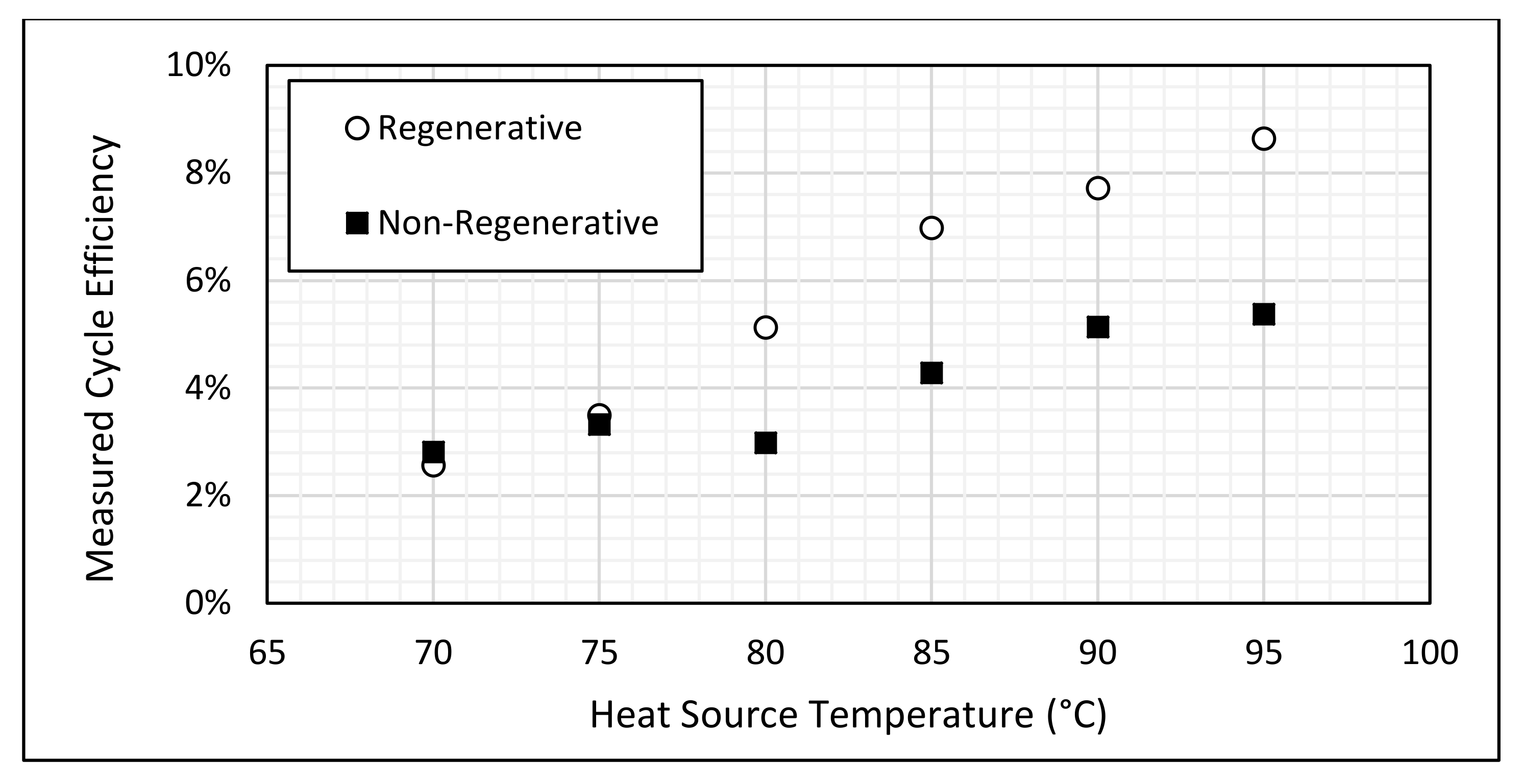
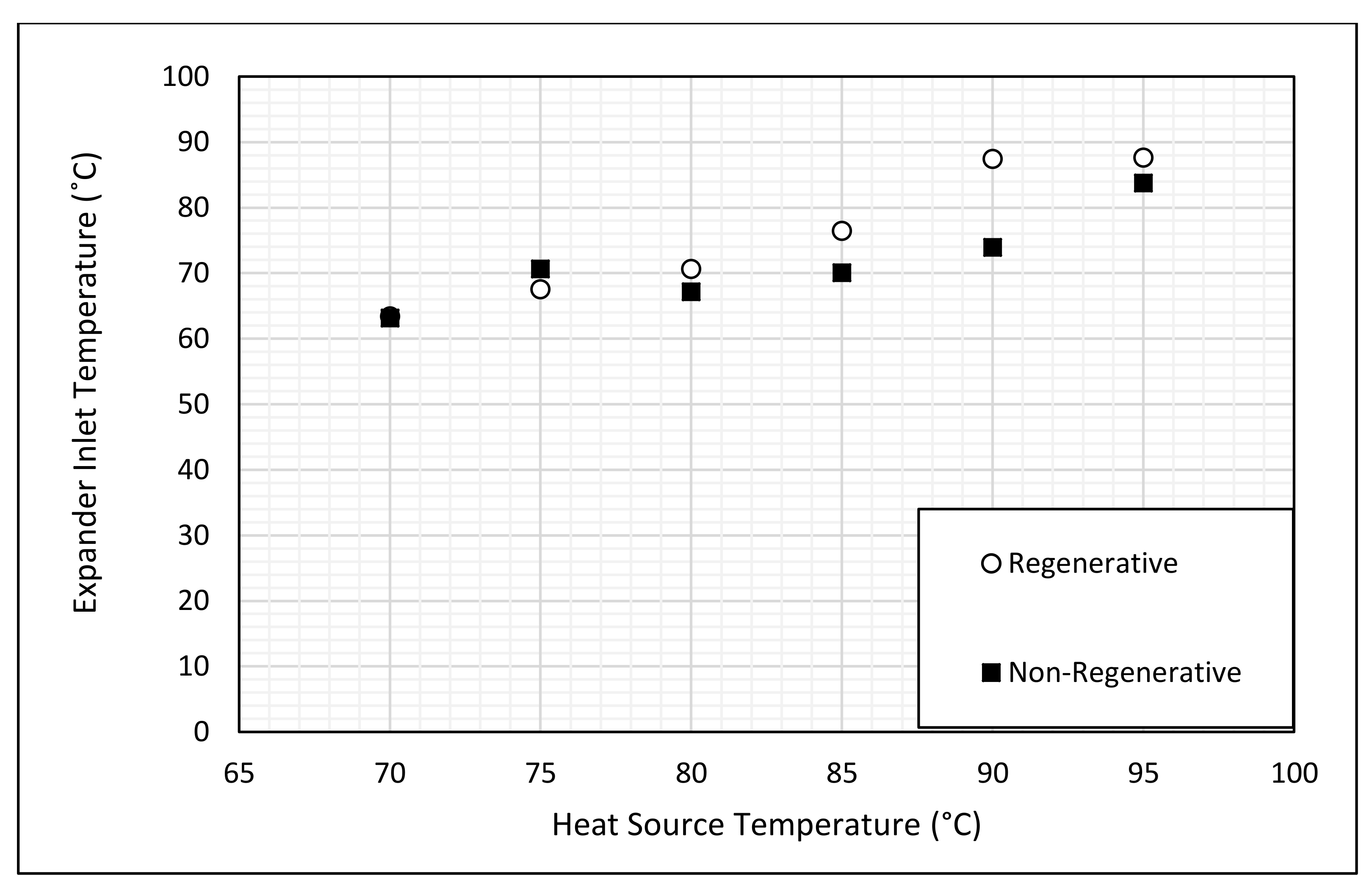
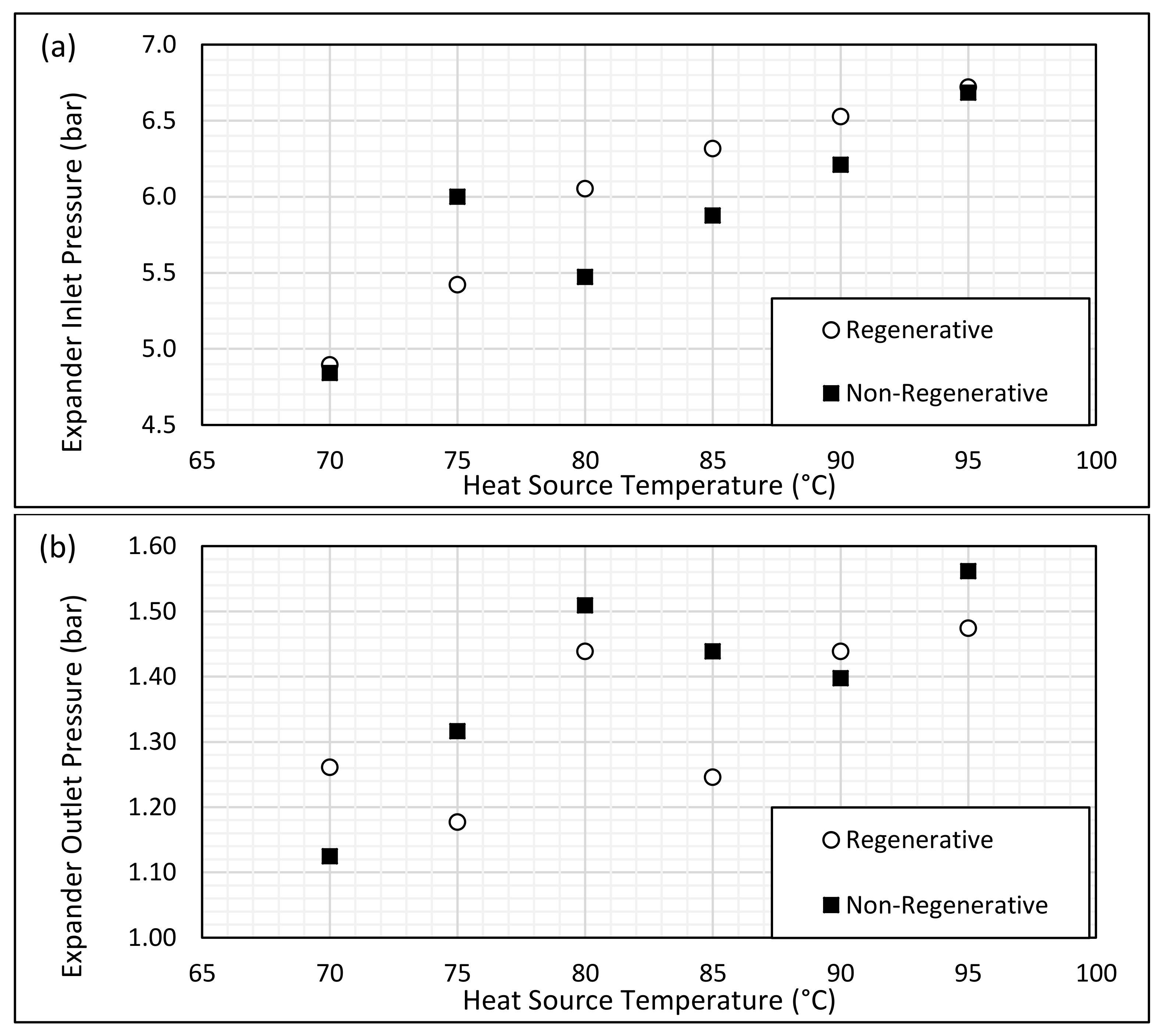
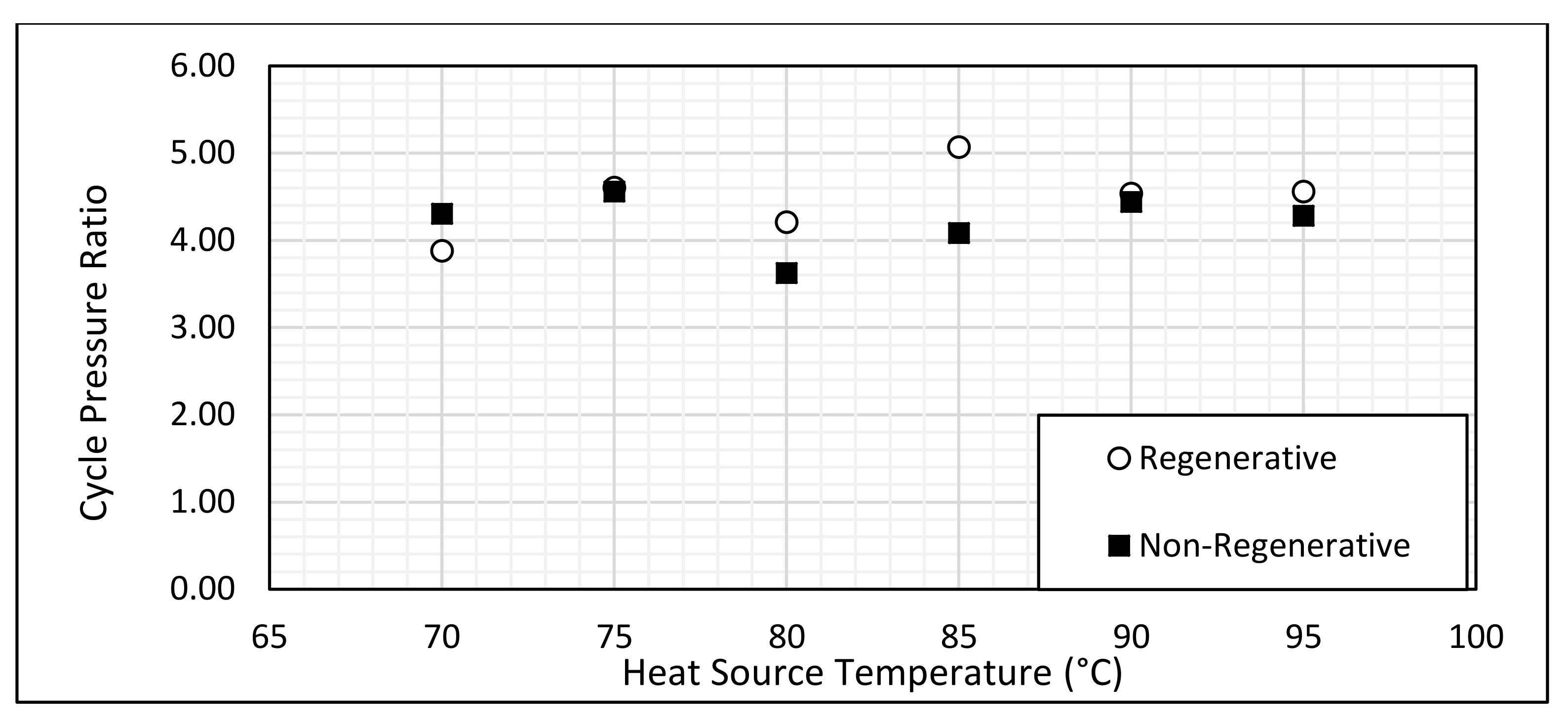
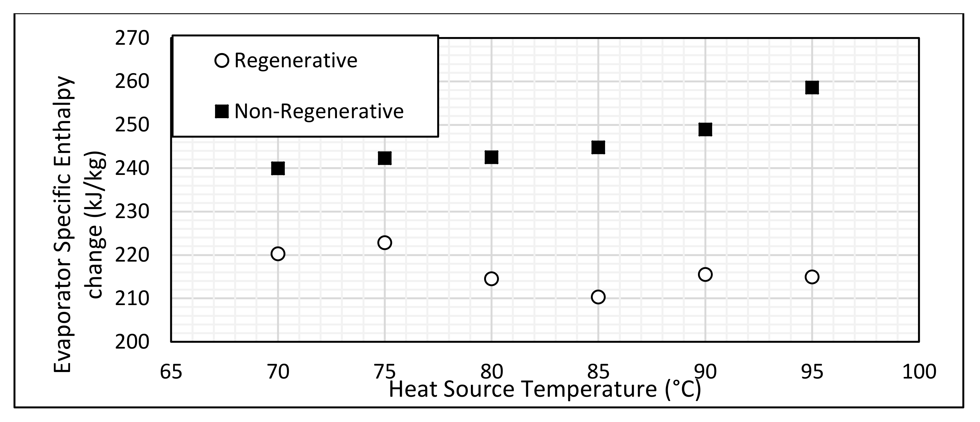
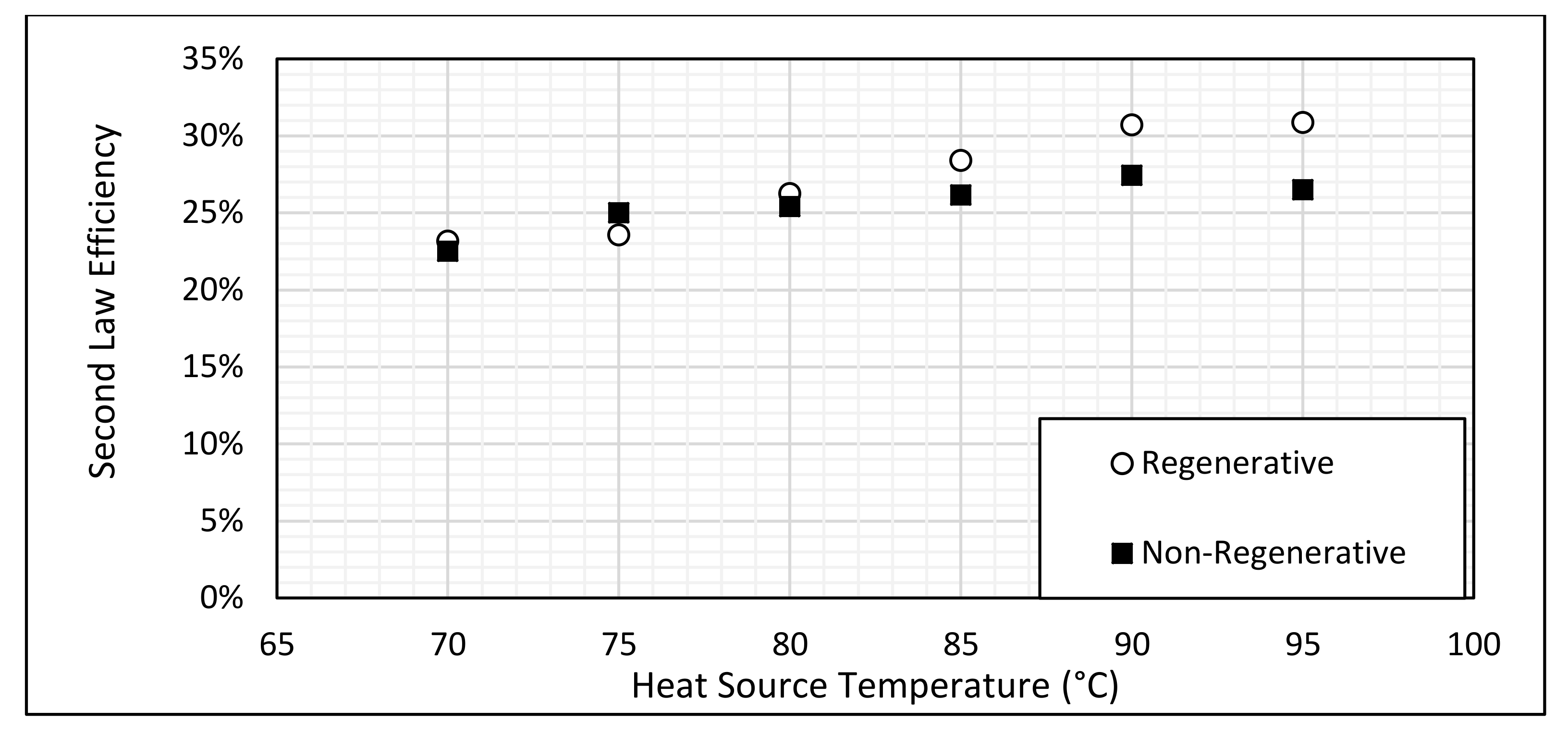
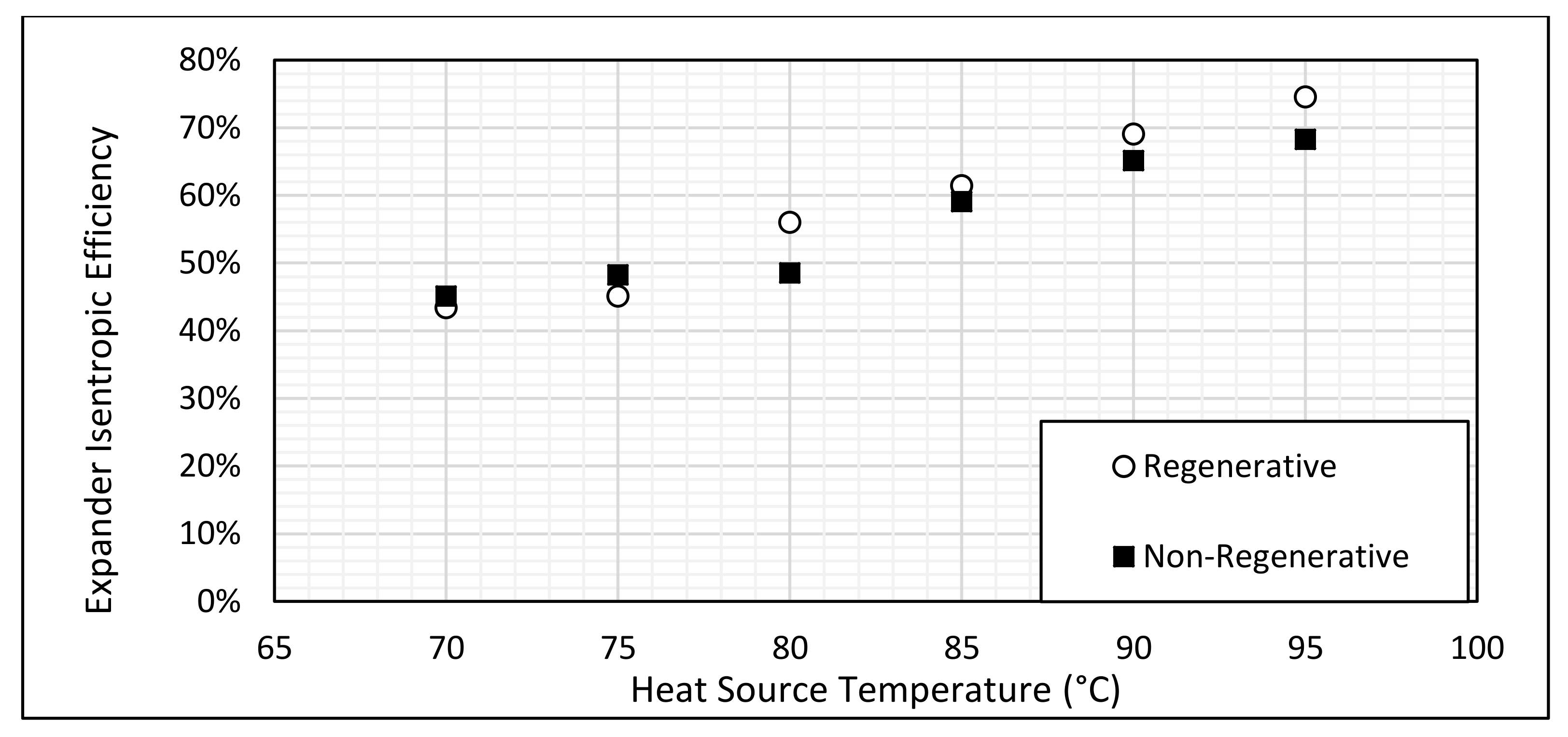
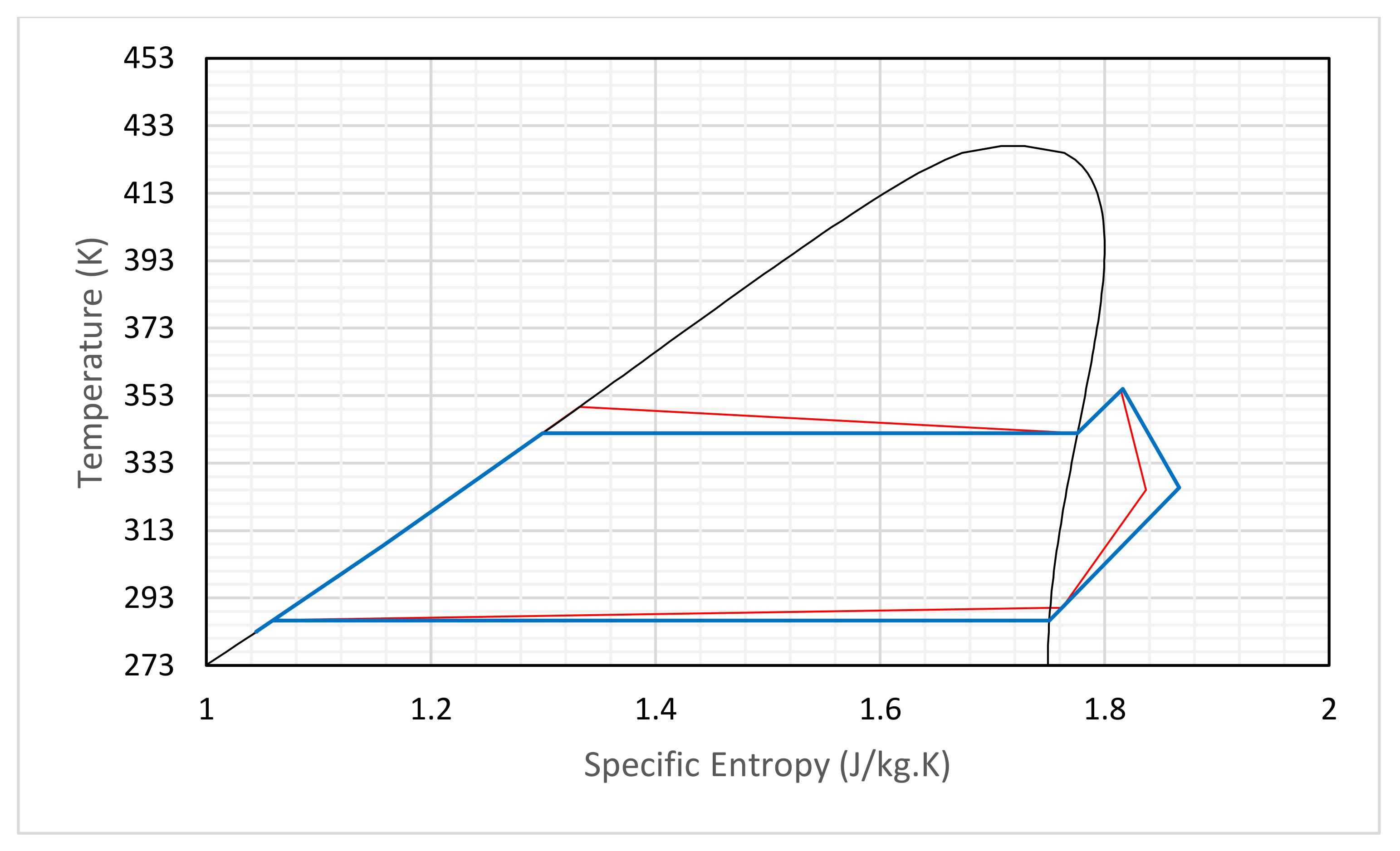
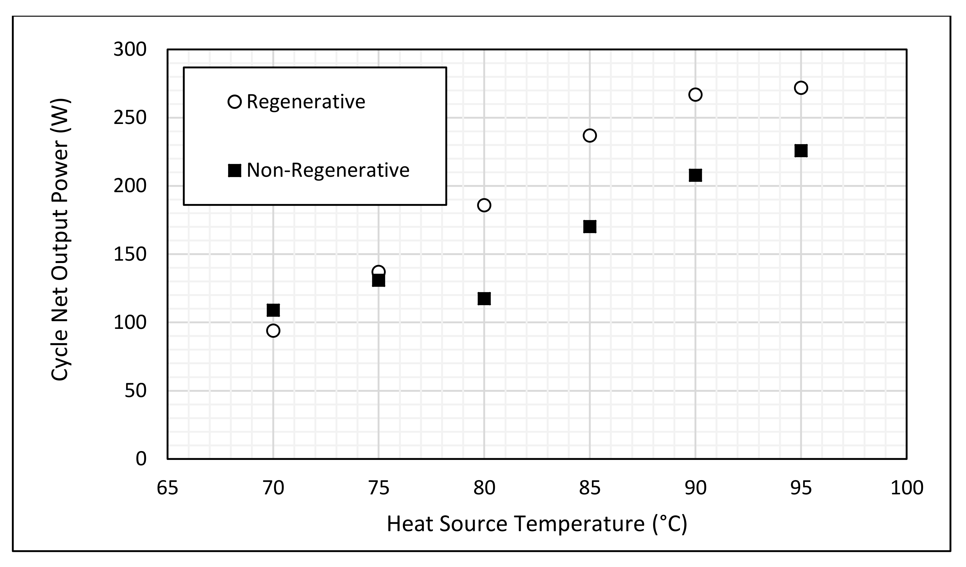
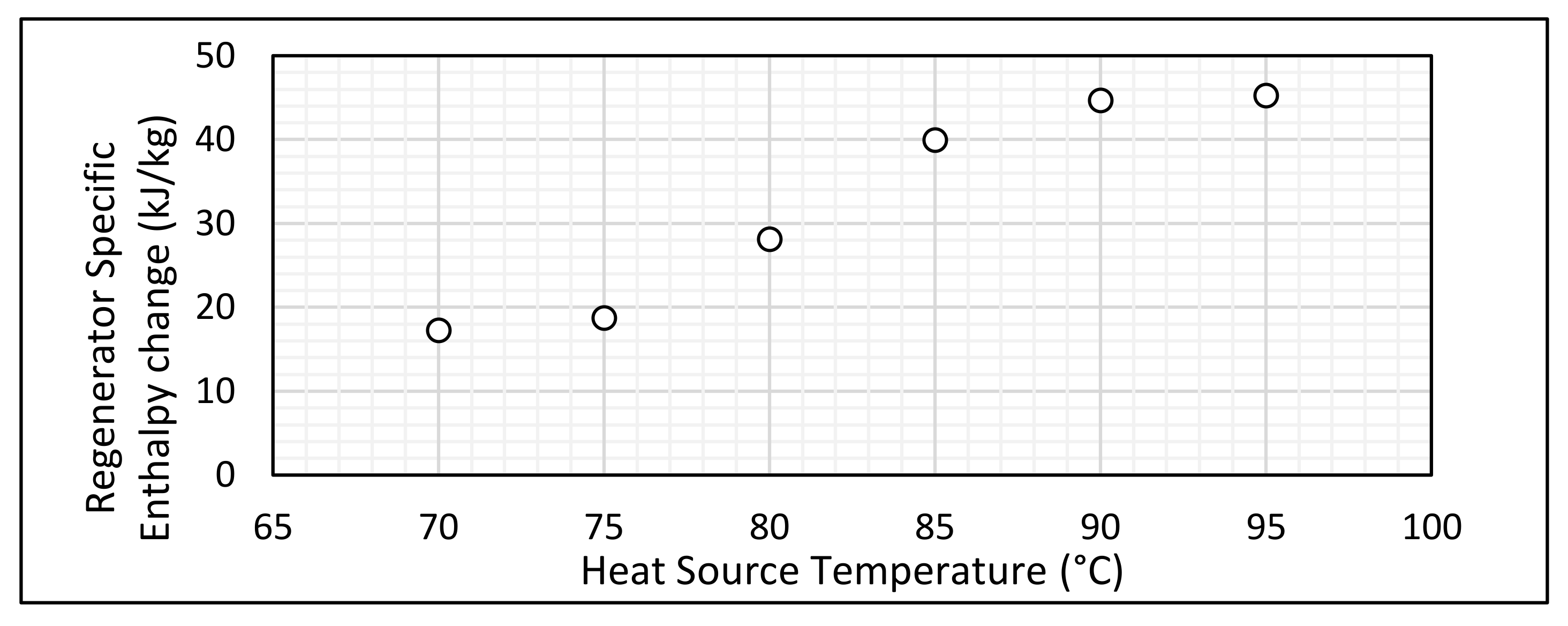
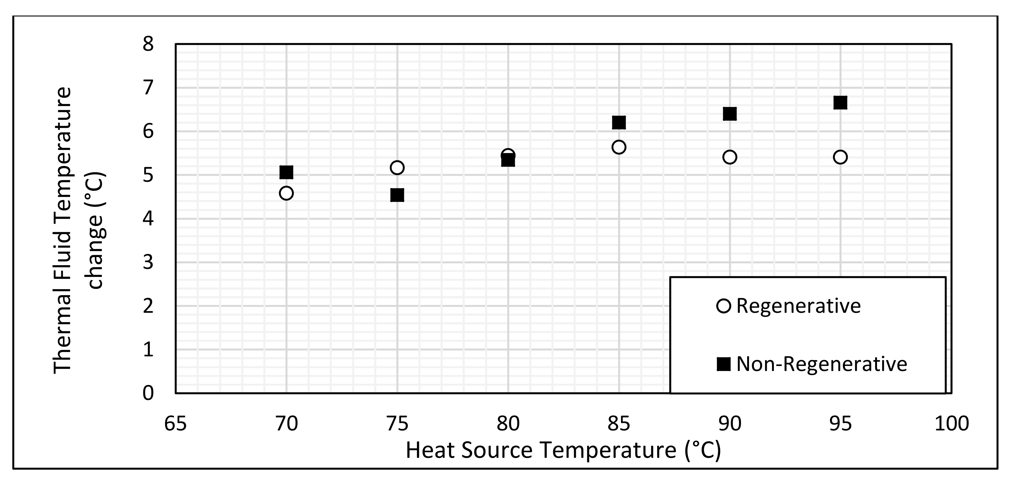
4.2. Comparison between Regenerative and Non-Regenerative Cycles

The trends of efficiency and cycle output power for both regenerative and non-regenerative cycles are presented in the figures below. The effects of the presence of a regenerator in the cycle are shown for a range of heat source temperatures, which are then analysed and discussed in detail.
Figure 4 shows how the efficiency of both the regenerative and non-regenerative cycles vary with changing heat source temperature. It can be seen that there is little difference between the two cycles at the lower heat source temperatures. As the heat source temperature increases, the efficiency of both cycles increases, but the regenerative cycle shows higher efficiencies than the non-regenerative cycle for heat source temperatures greater than 80 °C. At the lower heat source temperatures, the pump consumes more power than the power generated by the expander and generator, resulting in a net negative efficiency, and at the higher heat source temperatures, the expander and generator produce substantially more power than is consumed at the pump in both cycles, resulting in a positive net efficiency. The maximum efficiency for the regenerative case is 8.64%, and the maximum efficiency for the non-regenerative case is 5.37% when the heat source temperature reaches 95 °C.
Figure 5 shows the measured pump power input varying with the frequency of the inverter. The response is almost linear, increasing from 47 W at a frequency of 20 Hz to 120 W at a frequency of 40 Hz. As pump power is a function of the flow rate and the pressure head, it is independent from heat source temperatures and loads on the generator. The pressure ratio between the high-pressure and low-pressure sides of the cycle does not change significantly due to the fixed in-built volume ratio of the expander. As result, the pump power consumption in our tests mainly depends on the flow rate, which is determined by the pump frequency. Hence, the power consumption of liquid pump increases as the frequency increase in near linear fashion, as shown in Figure 5.
Figure 6 shows the variation in net power output from the rig as the heat source temperature changes for both the regenerative and non-regenerative cases. It can be seen that the net power output does increase roughly linearly with increasing heat source temperature, and that the net power output for the regenerative cycle increases more quickly with increasing temperature than the corresponding plot for the non-regenerative cycle. The divergence in the regenerative and non-regenerative plots above a heat source temperature of 80 °C can also be seen in this figure, with a maximum power output of 272 W for the regenerative case and a maximum power output of 226 W for the non-regenerative case, demonstrating the benefits of using a regenerative cycle.
Figure 7 shows how the expander inlet temperature varies as the heat source temperature changes for the regenerative and non-regenerative cycles. A higher expander inlet temperature is expected to result in a higher specific enthalpy drop across the expander. The data from Figure 7 suggests that the regenerator allows for a higher expander inlet temperature to be reached at higher heat source temperatures, which leads to an increase in the power output of the cycle.
Figure 8a shows how the expander inlet pressure varies as the heat source temperature changes, Figure 8b shows how the expander outlet pressure varies as the heat source temperature changes, and Figure 9 shows how the overall cycle pressure ratio varies as the heat source temperature changes. There is a slight increase in the expander inlet pressure with increasing heat source temperature. However, there is no clear trend in the cycle pressure ratio due to a corresponding increase in the expander outlet pressure. This is due to the fixed in-built volume ratio of the expander; as a result, the pressure ratio it can handle is more or less fixed. An increase in the expander outlet pressure such as the one observed here could be symptomatic of under expansion, as the expander is not able to effectively expand the working fluid from the increased inlet pressure.
Figure 10 shows how the specific enthalpy change across the evaporator varies with the changing heat source temperature for both the regenerative and non-regenerative cases. It can be seen that the evaporator enthalpy change for the regenerative case remains relatively constant over the range of heat source temperatures, while the evaporator enthalpy change for the non-regenerative case increases noticeably as the heat source temperature increases. For a heat source temperature of 70 °C, the regenerative cycle has an evaporator specific enthalpy change of 220 kJ/kg, and the non-regenerative cycle has an evaporator specific enthalpy change of 240 kJ/kg, which is a difference of 9%. For the heat source temperature of 95 °C, the regenerative cycle has an evaporator specific enthalpy change of 214 kJ/kg, and the non-regenerative cycle has an evaporator specific enthalpy change of 258 kJ/kg, which is a difference of 20.56%. This difference shows that the heat recovery from the vapour exiting the expander by the regenerator increases as the heat source temperature increases. Such heat recovery reduced the heat demand in the evaporator, leading to a higher thermal efficiency, as shown in Figure 6.
Figure 11 shows how the regenerator enthalpy change varies as the heat source temperature increases. This is due to the increased expander inlet temperature leading to a correspondingly increased expander outlet temperature, as shown in the T-s diagrams presented in Figure 12. It can be seen that the higher heat source temperature case (shown on the right) has a higher temperature drop across the expander, which explains the trend of increasing power output seen in Figure 6. It can also be seen that the superheat at the expander outlet is noticeably higher in the higher temperature case, giving a larger driving temperature differential for the regenerator if one is installed in the cycle, leading to higher heat recovery within the regenerator as shown in Figure 11, and consequently a higher thermal efficiency, as shown in Figure 6.
Figure 13 shows how the second-law efficiency of the cycle varies with the heat source temperature. The second law efficiency is—similarly to the first-law efficiency—higher for the regenerative cycle, and increases as the heat source temperature increases. A similar divergence between the data for the regenerative and non-regenerative cycles with increasing heat source temperature can be seen in this figure. This corresponds to both the increase in the power output seen from the cycle, as seen in Figure 6, and to a reduction in the temperature change of the thermal fluid in the hot side of the evaporator in the regenerative case, which can be seen in Figure 14. This reduction in temperature change is most likely to be due to the reduced heat demand from the evaporator, as previously shown in Figure 10.
Figure 15 shows how the isentropic efficiency of the expansion process varies as the heat source temperature changes. The isentropic efficiency is generally higher for the regenerative case, reaching a maximum of 74.5% for a heat source temperature of 95 °C, whereas the isentropic efficiency only reaches a value of 68.3% for the non-regenerative case. Lemort et al. [33] identified the major sources of isentropic inefficiency in the expander as inlet and discharge losses, volumetric inefficiency, leakage past the scrolls, thermal losses, electrical losses, and friction losses. Thermal losses are a function of the temperature difference between the inlet and the environment. Inlet and discharge losses increase along with the increasing volume flow rate, which is linked to the mass flow rate and density, and itself is a function of heat source temperature. Leakage is a function of the pressure ratio and expander rotational speed, while the mechanical and electrical losses are also a function of the rotational speed, and the volumetric efficiency is a function of the density and rotational speed. This suggests that the increase in isentropic efficiency with increasing temperature is due to the expander operating at a more favourable rotational speed due to an increased volume flow rate, or a greater enthalpy of expansion, making the losses less proportionally significant. Unfortunately, the data acquisition system was unable to collect more in-depth information about the expansion process, in particular the precise rotational speed of the expander, which would have enabled the investigation of the volumetric efficiency. This is an interesting area for future research, and would enable a deeper analysis of the performance of the expander.

5. Conclusions

A small ORC rig has been designed, constructed, and tested to investigate the effect of the regenerator on the system efficiency. The results from the experimental rig show a clear increase in the first-law efficiency by the introduction of a regenerator into the cycle, and this increase in efficiency becomes greater at increased heat source temperatures. There is also an increase in the second-law efficiency of the cycle with the addition of a regenerator and an increase in heat source temperature. The peak efficiency of the cycle was 8.61% for a regenerative cycle at a heat source temperature of 95 °C. The regenerative cycle showed a higher efficiency than the non-regenerative cycle, particularly for heat source temperatures above 75 °C. This was attributed to two factors. The first is the reduced heat demand in the evaporator, which is clear from the figures, and is the most intuitive benefit of a regenerator. The second factor is that the output power of the cycle increased when the regenerator was added. This appears to be due to an increased expander inlet temperature, something which is apparent from the recorded data. This is an interesting effect that has not been widely reported in the literature, although it is important to note that much of the potential economic benefit of a regenerator stems from its ability to reduce the required size of the evaporator and condenser, so a commercial system might not benefit from this increased expander inlet temperature.

Author Contributions

Conceptualization, Z.Y., E.W. and P.C.; Methodology, P.C. and A.M.; Investigation, P.C.; Resources, Z.Y.; Writing-Original Draft Preparation, P.C.; Writing-Review & Editing, P.C. and Z.Y.; Supervision, Z.Y.; Project Administration, Z.Y.; Funding Acquisition, Z.Y.

Funding

This research is funded by EPSRC (EP/N020472/1, EP/N005228/1, EP/N005228/1 and EP/R003122/1) in the United Kingdom.

Conflicts of Interest

The authors declare no conflict of interest.

References

  1. Hung, T.; Shai, T.; Wang, S. A review of Organic Rankine cycles (ORCs) for the recovery of low-grade waste heat. Energy 1997, 22, 661–667. [Google Scholar] [CrossRef]
  2. Budislistyo, D.; Krumdieck, S. A novel design methodology for waste heat recovery systems using organic Rankine cycle. Energy Convers. Manag. 2017, 142, 1–12. [Google Scholar] [CrossRef]
  3. Element Energy. The Potential for Recovering and Using Surplus Heat from Industry; Department of Energy and Climate Change: London, UK, 2014.
  4. Bianchi, M.; Pascale, A.D. Bottoming Cycles for Electric Energy Generation: Parametric Investigation of Available and Innovative Solutions for the Exploitation of Low and Medium Temperature Heat Sources. Appl. Energy 2011, 88, 1500–1509. [Google Scholar] [CrossRef]
  5. Nemati, A.; Nami, H.; Ranjbar, F.; Yari, M. A Comparative Thermodynamic Analysis of ORC and Kalina Cycles for Waste Heat Recovery: A Case Study for CGAM Cogeneration System. Case Stud. Therm. Eng. 2017, 9, 1–13. [Google Scholar] [CrossRef]
  6. Larjola, J. Electricity from Industrial Waste Heat using High-Speed Organic Rankine Cycle (ORC). Int. J. Prod. Econ. 1995, 41, 227–235. [Google Scholar] [CrossRef]
  7. Scardigno, D.; Fanelli, E.; Viggiano, A.; Braccio, G.; Magi, V. A genetic optimisaton of a hybrid organic Rankine plant for solar and low-grade energy sources. Energy 2015, 91, 807–815. [Google Scholar] [CrossRef]
  8. Ghasemian, E.; Ehyaei, M. Evaluation and Optimisation of Organic Rankine Cycle (ORC) with algorithms NSGA-II, MOPSO and MOEA for eight coolant fluids. Int. J. Energy Environ. Eng. 2018, 9, 39–57. [Google Scholar] [CrossRef]
  9. Prando, D.; Renzi, M.; Gasparella, A.; Baratieri, M. Monitoring of the Energy PErformance of a District HEating CHP Plant Based on Biomass Boiler and ORC Generator. Appl. Therm. Eng. 2015, 79, 98–107. [Google Scholar] [CrossRef]
  10. Navarro-Esbrí, J.; Molés, F.; Peris, B.; Mota-Babiloni, A. Small-Scale ORC Design for a Cogeneration Solar Biomass Supported Application. In Proceedings of the 3rd International Seminaro on ORC Power Systems, Brussels, Belgium, 12–14 October 2015. [Google Scholar]
  11. Peris, B.; Navarro-Esbrí, J.; Molés, F.; Collado, R.; Mota-Babiloni, A. Performance Evaluation of an Organic Rankine Cycle(ORC) for Power Applications from Low-Grade Heat Sources. Appl. Therm. Eng. 2015, 75, 763–769. [Google Scholar] [CrossRef]
  12. Molés, F.; Navarro-Esbrí, J.; Peris, B.; Mota-Babiloni, A. Experimental Evaluation of HCFO-1233zd-E as HFC-245fa replacement in an Organic Rankine Cycle System for Low Temperature Heat Sources. Appl. Therm. Eng. 2016, 98, 954–961. [Google Scholar] [CrossRef]
  13. Manolakos, D.; Kosmadakis, G.; Kyritsis, S.; Papadakis, G. On-site Experimental Evaluation of a Low-Temperature Solar Organic Rankine Cycle System for RO Desalination. Sol. Energy 2009, 83, 646–656. [Google Scholar] [CrossRef]
  14. Mikielewicsz, D.; Mikielewicz, J.; Wajs, J. Experiences from Operation of Different Expansion Devices for Application in Domestic Micro CHP. Arch. Thermodyn. 2010, 31, 3–13. [Google Scholar] [CrossRef]
  15. Liu, H.; Qiu, G.; Shao, Y.; Daminabo, F.; Riffat, S.B. Preliminary Experimental Investigations of a Biomass-fired Micro-Scale CHP with Organic RAnkine Cycle. Int. J. Low Carbon Technol. 2010, 5, 81–87. [Google Scholar] [CrossRef]
  16. Chang, J.-C.; Chang, C.-W.; Hung, T.-C.; Lin, J.-R.; Huang, K.-C. Experimental Study and CFD Approach for Scroll-Type Expander used in Low-Temperature Organic Rankine Cycle. Appl. Therm. Eng. 2014, 73, 1444–1452. [Google Scholar] [CrossRef]
  17. Yagoub, W.; Doherty, P.; Riffat, S. Solar Energy-Gas Driven Micro-CHP System for an Office Building. Appl. Therm. Eng. 2006, 26, 1604–1610. [Google Scholar] [CrossRef]
  18. Tang, H.; Wu, H.; Wang, X.; Xing, Z. Performance Study of a Twin-Screw Expander Used in a Geothermal Organic Rankine Cycle Power Generator. Energy 2015, 90, 631–642. [Google Scholar] [CrossRef]
  19. Yang, Y.M.; Park, B.-S.; Lee, S.W.; Lee, D.-H. Development of a Turbo-Generator for ORC System with Twin Radial Turbines and Gas Foil Bearings. In Proceedings of the 3rd International Seminar on ORC Power Systems, Brussels, Belgium, 12–14 October 2015. [Google Scholar]
  20. Quoilin, S.; Broek, M.V.D.; Declaye, S.; Dewaller, P.; Lemort, V. Techno-economic survey of Organic Rankine cycle (ORC) Systems. Renew. Sustain. Energy Rev. 2013, 22, 168–186. [Google Scholar] [CrossRef]
  21. Landelle, A.; Tauveron, N.; Haberschill, P.; Revellin, R. Organic Rankine Cycle Design and Performance Comparison based on Experimental Database. Appl. Energy 2017, 204, 1172–1187. [Google Scholar] [CrossRef]
  22. Yamada, N.; Tominaga, Y.; Yoshida, T. Demonstration of 10Wp micro organic Rankine cycle generator for low-grade heat recovery. Energy 2014, 78, 806–813. [Google Scholar] [CrossRef]
  23. Gao, P.; Jiang, L.; Wang, L.W.; Wang, R.; Song, F. Simulation and Experiments on an ORC System with Different Scroll Expanders based on Energy and Exergy Analysis. Appl. Therm. Eng. 2015, 75, 880–888. [Google Scholar] [CrossRef]
  24. Liu, Q.; Duan, Y.; Yang, Z. Effect of Condensation Temperature Glide on the Performance of Organic Rankine Cycles with Zeotropic Mixture Working Fluids. Appl. Energy 2014, 115, 394–404. [Google Scholar] [CrossRef]
  25. Cho, S.-Y.; Cho, C.-H.; Choi, S.-K. Experiment and Cycle Analysis on a Partially-Admitted Axial-Type Turbine Used in the Organic Rankine Cycle. Energy 2015, 90, 643–651. [Google Scholar] [CrossRef]
  26. Algieri, A.; Morrone, P. Techno-economic analysis of biomass-fired ORC systems for single-family combined heat and power (CHP) applications. Energy Procedia 2014, 45, 1285–1294. [Google Scholar] [CrossRef]
  27. Amicabile, S.; Lee, J.-I.; Kum, D. A comprehensive design methodology of organic Rankine cycles for the waste heat recovery of automotive heavy-duty diesel engines. Appl. Therm. Eng. 2015, 87, 574–585. [Google Scholar] [CrossRef]
  28. Wei, F.; Senchuang, G.; Zhonghe, H. Economic analysis of Organic Rankine Cycle (ORC) and Organic Rankine Cycle with internal heat exchanger (IORC) based on industrial waste heat source constraint. Energy Procedia (Hong Kong) 2019, 158, 2403–2408. [Google Scholar] [CrossRef]
  29. Airsquared Inc. July 2018. Available online: https://airsquared.com/products/scroll-expanders/e15h022a-sh/ (accessed on 14 April 2019).
  30. Wanner Engineering G20 Series Datasheet. July 2018. Available online: https://www.hydra-cell.eu/docs/Sales-Lit-Extranet-Datasheets/G20-Datasheet.pdf (accessed on 14 April 2019).
  31. ELemmon, M.H.; McLinden, M. NIST Standard Reference Database 23: Reference Fluid Thermodynamic and Transport Properties-REFPROP, Version 9.1, National Institute of Standards and Technology, Standard Reference Data Program; Standard Reference Data Program: Gaithersburg, MD, USA, 2013. [Google Scholar]
  32. Collings, P.; Yu, Z. Numerical Analysis of an Organic Rankine Cycle with Adjustable Working Fluid Composition, a Volumetric Expander and a Recuperator. Energies 2017, 10, 440. [Google Scholar] [CrossRef]
  33. Lemort, V.; Quoilin, S.; Cuevas, C.; Lebrun, J. Testing and Modeling a Scroll Expander Integrated into an Organic Rankine Cycle. Appl. Therm. Eng. 2009, 29, 3094–3102. [Google Scholar] [CrossRef]
Figure 1. Schematic diagram of the ORC test rig.
Energies 12 01452 g001
Figure 2. T-s diagram of the highest efficiency case. Regenerative portions of the cycle shown in green.
Energies 12 01452 g002
Figure 3. Comparative T-s diagrams of the highest efficiency case, and the theoretical prediction for these parameters. The theoretical case is indicated by a blue line, and the experimental case is indicated by a red line.
Energies 12 01452 g003
Figure 4. Variation in measured cycle efficiency with varying heat source temperature for regenerative and non-regenerative cycles, for a pump speed of 40 Hz.
Energies 12 01452 g004
Figure 5. Pump power consumption with varying inverter frequency.
Energies 12 01452 g005
Figure 6. Variation in cycle net power output with varying heat source temperatures for regenerative and non-regenerative cycles, for a pump speed of 40 Hz.
Energies 12 01452 g006
Figure 7. Variation in expander inlet temperature with changing heat source temperature.
Energies 12 01452 g007
Figure 8. Variation in expander inlet (a) and outlet (b) pressure with changing heat source temperature.
Energies 12 01452 g008
Figure 9. Variation in cycle pressure ratio with changing heat source temperature.
Energies 12 01452 g009
Figure 10. Variation in evaporator-specific enthalpy change with changing heat source temperature for regenerative and non-regenerative cycles and a pump speed of 40 Hz.
Energies 12 01452 g010
Figure 11. Variation in regenerator-specific enthalpy change as the heat source temperature changes for a pump speed of 40 Hz.
Energies 12 01452 g011
Figure 12. Comparison of T-s diagrams for heat source temperatures of 65 °C (left) and 95 °C (right).
Energies 12 01452 g012
Figure 13. Variation in second-law efficiency of the cycle with changing heat source temperature.
Energies 12 01452 g013
Figure 14. Plot of the temperature change in the thermal fluid with changing heat source temperature for the regenerative and non-regenerative cycles.
Energies 12 01452 g014
Figure 15. Variation of expander isentropic efficiency with changing heat source temperature for the regenerative and non-regenerative cycles.
Energies 12 01452 g015
Table 1. Details of the chosen expander [25].
ManufacturerAirsquared
TypeScroll, semi-hermetic
Nominal Output1 kWe
Volume Ratio3.5
Displacement14.5 cm3/rev
Max Speed3600 RPM
Max Inlet Pressure13.8 bar
Max Inlet Temperature175 °C
Table 2. Details of the working fluid pump [30].
ManufacturerHydra-Cell
TypeDiaphragm
Diaphragm MaterialPTFE
Head MaterialPolypropylene
Max flow rate3.8 L/min
Max Pressure24 bar
MotorSingle-phase AC, inverter driven
Table 3. Details of the heat exchangers.
ManufacturerSondex Ltd.
TypeBrazed Plate
MaterialCopper
Number of plates30
Plate Area0.021 m2
Total Heat Transfer Area1.26 m2
Channel Thickness1.9 mm
Plate Thickness0.4 mm
Max Rated Temperature185 °C
Max Rated Pressure25 bar
Table 4. Key data of the highest efficiency case.
ParameterExperimentalCalculationUnits
Heat source temperature90 ± 0.290°C
Heat sink temperature 77°C
Generator power output352315W
Pump power input9016W
Net power262299W
Isentropic efficiency of expander7470%
Heat absorbed by working fluid in evaporator36173660W
Heat reduction of the thermal fluid in evaporator38323660W
Cycle efficiency6.8 8.2%
Evaporator pressure5.82 ± 0.0155.82Bar
Condenser pressure1.4 ± 0.00351.4Bar
Cycle pressure ratio4.136–4.1754.16

