Article

Anti-Interference and Location Performance for Turn-to-Turn Short Circuit Detection in Turbo-Generator Rotor Windings

North China Electric Power University Dept. of Electrical Engineering State Key Laboratory of Alternate Electrical Power System with Renewable Energy Sources, Baoding 071003, China
*
Author to whom correspondence should be addressed.
Energies 2019, 12(7), 1378; https://doi.org/10.3390/en12071378
Submission received: 28 February 2019 / Revised: 25 March 2019 / Accepted: 30 March 2019 / Published: 10 April 2019
(This article belongs to the Special Issue Analysis for Electrical Machines Monitoring)

Abstract

:
Online and location detection of rotor winding inter-turn short circuits are an important direction in the field of fault diagnosis in turbo-generators. This area is facing many difficulties and challenges. This study is based on the principles associated with the U-shaped detection coil method. Compared with dynamic eccentricity faults, the characteristics of the variations in the main magnetic field after a turn-to-turn short circuit in rotor windings were analyzed and the unique characteristics were extracted. We propose that the degree of a turn-to-turn short circuit can be judged by the difference in the induction voltage of the double U-shaped detection coils mounted on the stator core. Here, the faulty slot position was determined by the local convex point formed by the difference in the induced voltage. Numerical simulation was used here to determine the induced voltage characteristics in the double U-shaped coils caused by the turn-to-turn short circuit fault. We analyzed the dynamic eccentricity fault as well as combined the fault of a turn-to-turn short circuit and dynamic eccentricity. Finally, we demonstrate the positive anti-interference performance associated with this fault detection method. This new online detection method is satisfactory in terms of sensitivity, speed, and positioning, and overall performance is superior to the traditional online detection methods.

1. Introduction

Small- and medium-capacity turbo-generator units in China’s power system have gradually been eliminated except for the power stations used for urban heat supply. Some 300 MW units, as well as large-capacity turbo-generator units of 600 MW, 1000 MW, or above, have been retained, which have been adopted at most thermal power stations and nuclear power stations. These units have large electromagnetic loads, especially the rotor windings, and they must bear large mechanical and thermal stresses under strong vibration conditions. If turn-to-turn insulation is weak, a turn-to-turn short circuit fault can easily occur.
The most troublesome problem for turbo-generator rotor windings caused by turn-to-turn short circuit faults is the deterioration that occurs in the vibration state. Sometimes, rotor grounding and shaft magnetization issues occur as well. Usually, 1–1.5 months are required to address and resolve this problem. This includes finding, processing, and repairing the turn-to-turn short circuit fault in the rotor winding. When this happens, serious economic losses are incurred by the power plants, including the loss of generating capacity, labor costs, and energy available for starting and stopping machines repeatedly, as well as service life loss. Therefore, serious problems caused by fault deterioration can be avoided if the turn-to-turn short circuit in the turbo-generator rotor winding can be assessed more accurately. If the short circuit can be found more effectively, timely warnings can be provided at the early stage so many problems can be avoided. Also, the accurate localization of a fault can reduce fault processing time and reduce economic losses to a great extent. In this case, work in this area has certain value and prospects [1,2,3].
For turbo-generators, various kinds of online detection methods capable of detecting turn-to-turn short circuits in rotor windings have been proposed. For example, Mladen Šašić et al. [4] detected the symmetry of each slot leakage flux in the rotor using a micro-probe. According to the symmetry, they determined if a turn-to-turn short circuit occurred. Rastko Fišer et al. [5] proposed installing a small magnetic flux probe on the stator core “tooth unit”. This allowed users to confirm the short circuit’s position in the rotor winding using the difference in induced voltages on the probe according to the corresponding slots in the normal pole and the fault pole. In Li Yonggang et al. [6], the turn-to-turn short circuit in rotor windings was judged by the relative deviation between the theoretical and actual values of the excitation current. In Wu Yucai, et al. [7], turn-to-turn short circuits in rotor windings were judged by the deviation between the actual electromagnetic power and expected electromagnetic power. In Wu Yucai, et al. [8], a detection method without the use of a sensor was proposed. Here, the turn-to-turn short circuit was judged by the induced voltage harmonic of piercing screw in the stator core. In addition, shaft voltage harmonics [9,10], no-load electromotive force deviation [11], end leakage flux harmonics [12], and parallel branch circulation in the stator winding [13] have all been used to confirm whether the existence of a turn-to-turn short circuit fault in a rotor winding. For nearly half of these detection methods, excitation current data must be acquired from the turbo-generator including the excitation current method, virtual power method, and expected electromotive force method. These types of methods are inapplicable to large-capacity nuclear power units that use brushless excitation technology as a general rule. For the detection methods independent of excitation current, the detection coil method has been put into practical use. With this method, there is small interference under no-load or short circuit conditions in the turbo-generator and the detection effect is relatively good. When working under load, the output voltage waveform in the detection coil becomes insensitive to the turn-to-turn short circuit fault. This occurs due to the influence of the armature field, so the sensitivity drops sharply. Therefore, for this method, units are adjusted to a no-load or short circuit condition to finish the test after estimating that the turbo-generator is having a problem with a turn-to-turn short circuit in the rotor winding. In this case, online performance cannot be completely assessed, and though it is a method that can improve sensitivity, real-time evaluation is not possible. Wu Yucai et al. [14] proposed installing a U-shaped magnetic field detection coil inside the turbo-generator. Then, the turn-to-turn short circuit fault in the rotor winding was judged using the even or fractional sub-harmonic in the induced voltage of U-shaped coil. This U-shaped detection coil method is based on the asymmetry of the north and south magnetic pole fields in the faulty turbo-generator. In this case, users are not limited by the excitation mode of the turbo-generator; however, t another fault like a turn-to-turn short circuit fault can occur in rotor windings. This is known as the rotor eccentricity fault, where the magnetic field asymmetry of the turbo-generator is caused by dynamic eccentricity, which is stronger on the small air gap side and weaker on the large air gap side. When the turn-to-turn short circuit for rotor windings are judged using the U-shaped coil method, the first step is to eliminate the interference of the dynamic eccentricity fault because dynamic eccentricity faults are common in turbo-generators. Here, success or failure depends on whether the eccentricity interference is eliminated.
In terms of the anti-interference performance, the same shortcomings generally exist for all detection methods based on using the magnetic field. When the operating state of a turbo-generator changes rapidly (the reactive power also changes rapidly), the induced voltage waveforms of the sensor are not comparable at different times. In this case, it is possible to receive a false alarm signal when operating in a normal state, so an unnecessary shutdown may occur. In addition, most of the detection sensors have only a single function and they can only be used to detect turn-to-turn short circuit faults for rotor windings. If turn-to-turn short circuits in rotor windings and dynamic eccentricity faults can be detected simultaneously using the same kind of sensor, the monitoring systems for turbo-generators will be perfected and capable of simplifying the structure of detection sensors.
In this study, the influence of turn-to-turn short circuits in rotor windings on the main magnetic field of a turbo-generator was deduced. Similarity comparisons with dynamic eccentricity faults were conducted, and an online detection method for turn-to-turn short circuits in rotor winding based on double U-shaped coils was designed. We used to numerical simulation to prove that the fault features of turn-to-turn short circuit faults extracted from the new signal acquisition method are not covered by dynamic eccentricity faults, and the fault location can be determined. After the turn-to-turn short circuit fault is eliminated, the new detection method can be used to judge the rotor for a dynamic eccentricity fault.

2. Principle of Detection Methods

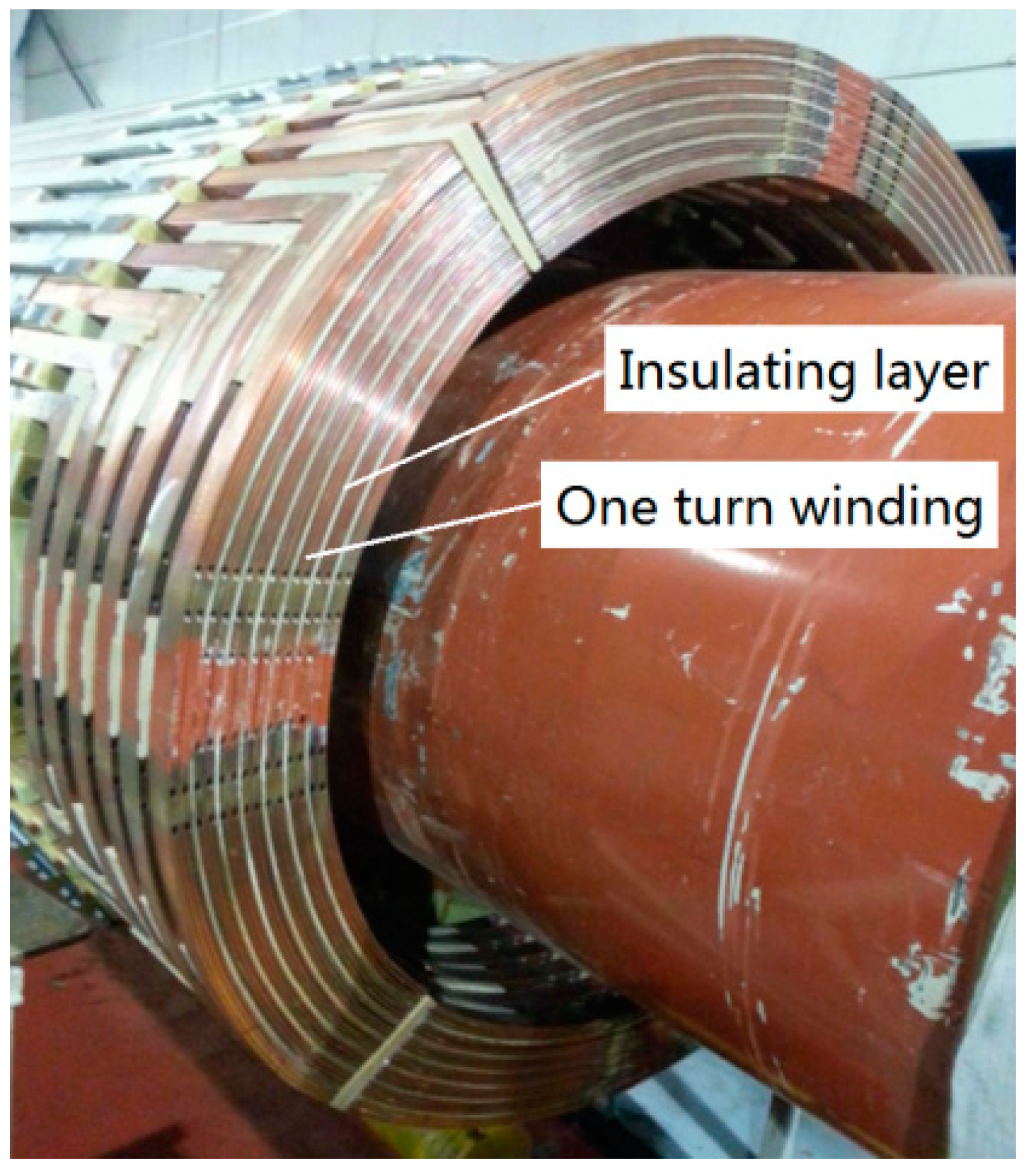
The rotor winding of a turbo-generator has a distributed structure. A certain number of excitation windings (generally 6–10 turns) are placed in each slot of the rotor and they are insulated by insulating layers, as shown in 
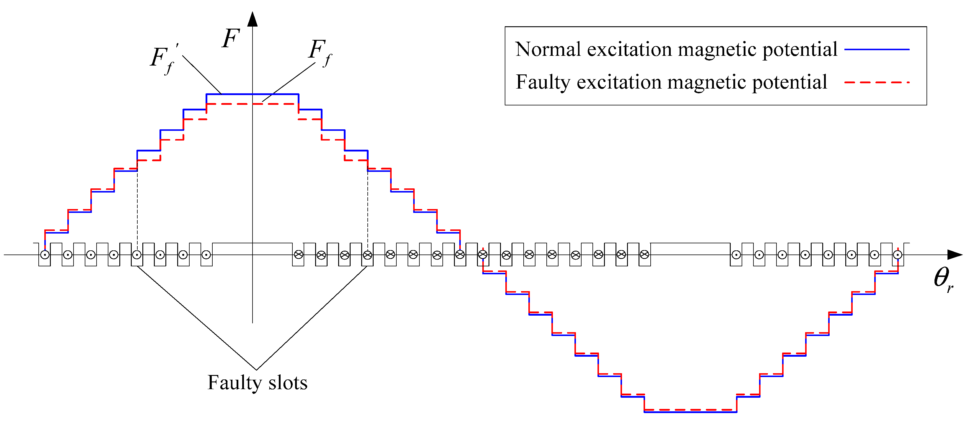
Figure 1. According to ampere circuital theorem, the excitation magneto motive force in a turbo-generator is a stepped wave, as shown in Figure 2. The amount of stepped wave in each slot of the rotor is related to the effective ampere turns of the slot. The larger the number of effective ampere turns, the larger the step amount. In the normal state of rotor winding, the number of winding turns for the rotor north and south poles is the same and the number of effective ampere turns is also the same. So, the excitation magnetic force is symmetrical. If a turn-to-turn short circuit fault occurs in a slot winding of the rotor, the current of the short circuited winding in the slot is zero, and the step amount of the excitation magnetic force in the slot decreases. In this case, the entire excitation magnetic force exists in an asymmetrical state.
F f ( θ r ) = 4 I f π i = 1 { k = 1 N a k sin [ ( 2 i 1 ) π γ + 2 k β 2 ] } × ( 1 ) 2 i 1 i 1 cos p ( 2 i 1 ) θ r
F f ( θ r ) = 4 I f π i = 1 { k = 1 N a k sin [ ( 2 i 1 ) π γ + 2 k β 2 ] } × ( 1 ) 2 i 1 i 1 cos p ( 2 i 1 ) θ r 2 Q I f π j = 1 sin j ( π γ + 2 m β 2 ) j × cos j θ r
where Fi represents the amplitude of the ith harmonic magnetic potential, i is an odd number, θr represents the spatial mechanical angle of the rotor, p represents the pole pair of the turbo-generator, ak represents the number of windings in the kth slot, γ is the angle at which the large gear of the rotor occupies the circumference of the rotor, If represents the excitation current, m is the number of short circuit slots, and Q is the number of short circuit turns.
When the rotor winding is normal, the excitation magneto motive force waveform is symmetrical, and the stepped magnetic potential waveform contains only the fundamental wave and the odd harmonic after the Fourier decomposition. This is shown in Equation (1).
When the turn-to-turn short circuit in a rotor winding occurs, the asymmetric stepped excitation magnetic force contains even or fractional harmonics after the Fourier decomposition. The excitation magnetic force is shown in Equation (2) [15]. Here, the blue item is the magnetic potential loss in the excitation winding which has short circuited. This is shown by the equation where j = 1, 2, 3, 4...:
The eccentricity of the rotor can be expressed as:
ε = | g g 0 g 0 | × 100 %
where g represents the largest or shortest air gap length of the turbo-generator and g0 represents the average air gap length of the turbo-generator.
It is assumed that the air gap in the turbo-generator is uniform, g(θr) = g0 and that the air gap permeability is constant. Therefore, this can be expressed as:
Λ ( θ r ) = μ 0 g ( θ r ) = μ 0 g 0
where, μ0 represents the permeability of the vacuum.
The excitation field of the turbo-generator can be expressed as Equation (5):
B ( θ r ) = F f ( θ r ) Λ ( θ r )
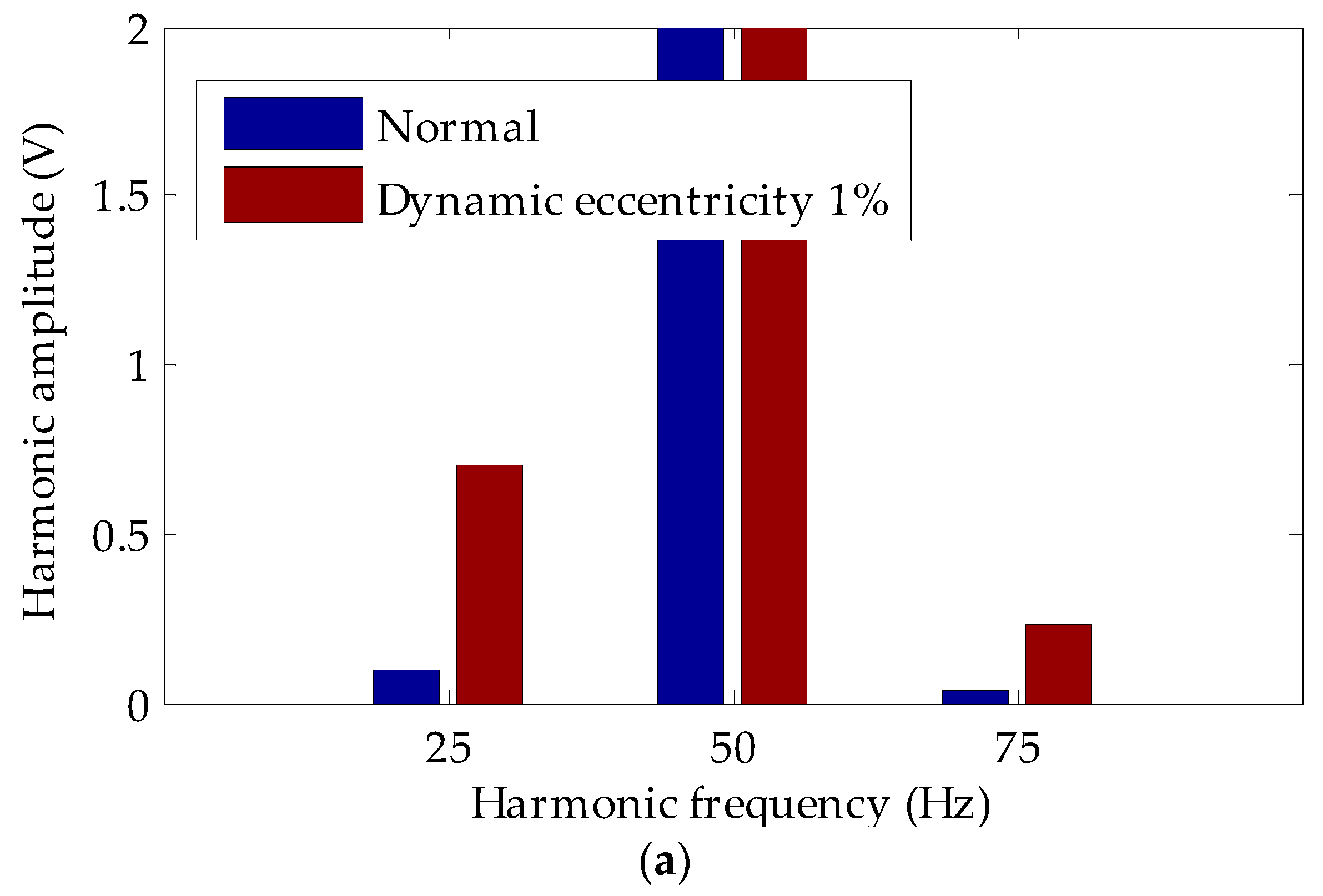
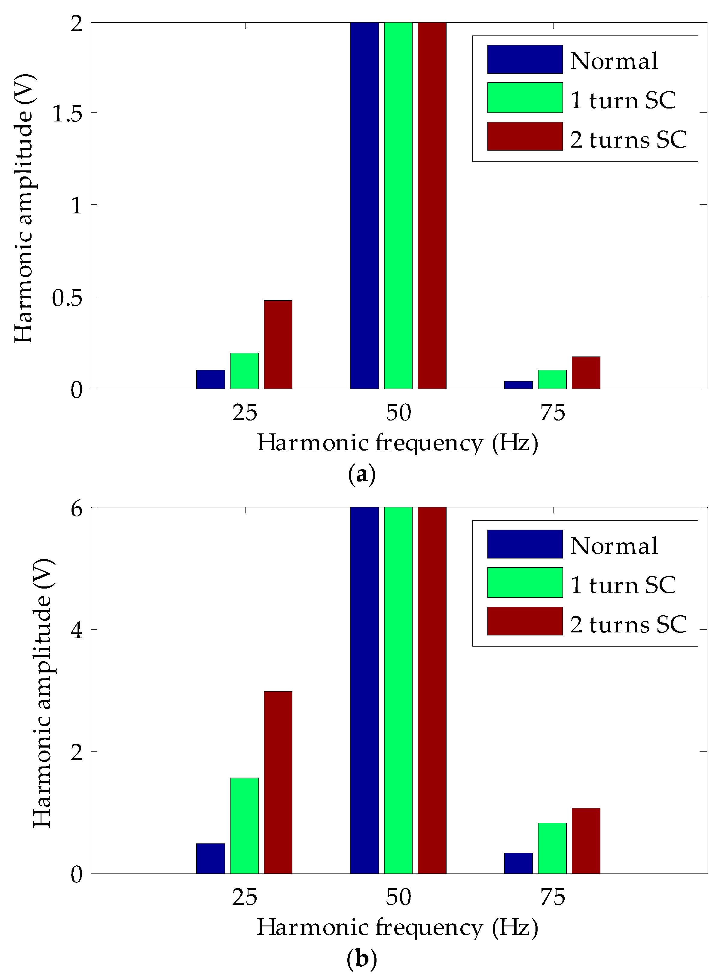
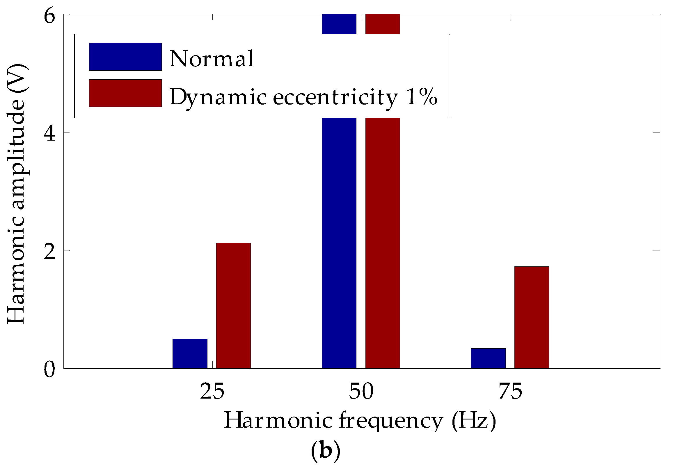
Equation (5) shows that some new harmonics appear in the excitation magnetic field after the turn-to-turn short circuit fault occurs in the turbo-generator rotor winding. For a 2-pole turbo-generator, even harmonics can occur 2, 4, and 6 times, and these will be generated in the excitation magnetic field; for the 4-pole turbo-generator, the 1/2, 3/2, 2, and 5/2 times harmonics do not exist when the rotor winding is normal.
The main magnetic field asymmetry of a turbo-generator can also be caused by the dynamic eccentricity of the rotor. In an abnormal state, the length of the air gap at any position changes periodically with time. If the slot effect, saturation effect, and higher harmonics are neglected, the length of the air gap in the synchronous rotating coordinate system can be expressed as [16]:
g ( θ r ) = g 0 | g g 0 | cos ( θ r + β )
where β represents the angle between the shortest air gap and axis d of the rotor.
Accordingly, the air gap permeance of the turbo-generator can be expressed as:
Λ ( θ r ) = μ 0 g ( θ r ) = μ 0 g 0 | g g 0 | cos ( θ r + β ) = μ 0 g 0 1 1 ε cos ( θ r + β ) μ 0 g 0 [ 1 + ε cos ( θ r + β ) ]
where ε is the relative eccentric ratio.
The air gap synthetic magnetic potential of the turbo-generator is equal to the superposition of excitation magnetic potential and armature reaction magnetic potential, which contains only odd harmonics. According to the air gap magnetic permeance method, the main magnetic field can be expressed as Equation (8):
B ( θ r ) = F ( θ r ) Λ ( θ r ) = [ F 1 cos p ( θ r + α 1 ) + F 3 cos 3 p ( θ r + α 3 ) ] × μ 0 g 0 [ 1 + ε cos ( θ r + β ) ] = μ 0 g 0 [ F 1 cos p ( θ r + α 1 ) + F 3 cos 3 p ( θ r + α 3 ) ] + μ 0 ε 2 g 0 { F 1 cos [ ( p + 1 ) θ r + p α 1 + β ] + F 1 cos [ ( p 1 ) θ r + p α 1 β ] + F 3 cos [ ( 3 p + 1 ) θ r + 3 p α 3 + β ] + F 3 cos [ ( 3 p 1 ) θ r + 3 p α 3 β ] }
where α1 and α3 represent the phase of the fundamental and third harmonics magnetic potential, respectively; and F1 and F3 represent the amplitude of the fundamental and third harmonics magnetic potential, respectively.
The blue item in Equation (8) appears after the fault, including the p + 1, p − 1, 3p + 1, and 3p − 1 harmonic components, which rotate synchronously with the rotor. For a 2-pole turbo-generator (p = 1), there is no direct current component, and 2nd and 4th harmonics are in the magnetic field before the fault; for a 4-pole turbo-generator (p = 2), there are no 1/2, 3/2, 5/2, and 7/2 harmonics in the magnetic field before the fault.
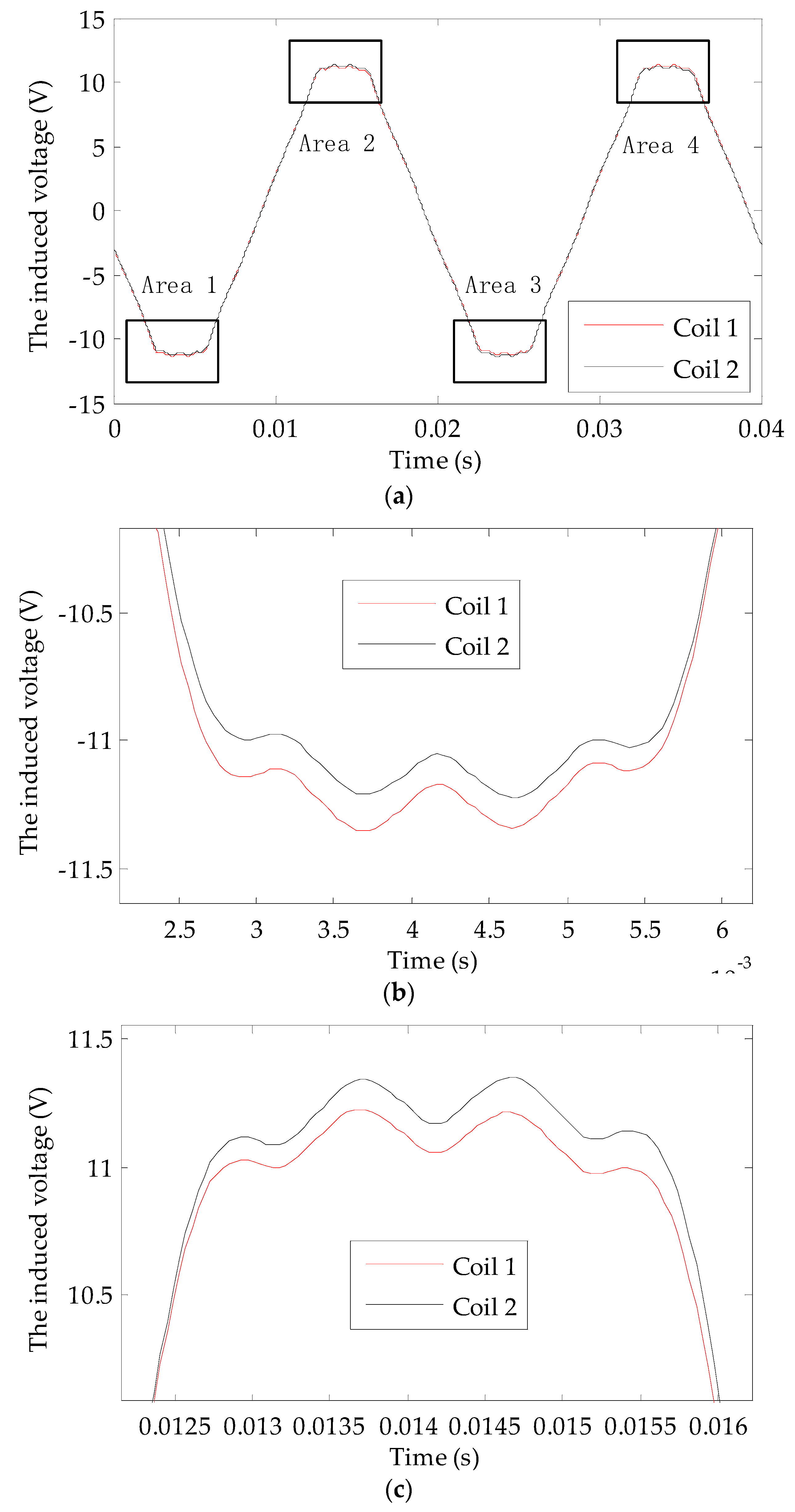
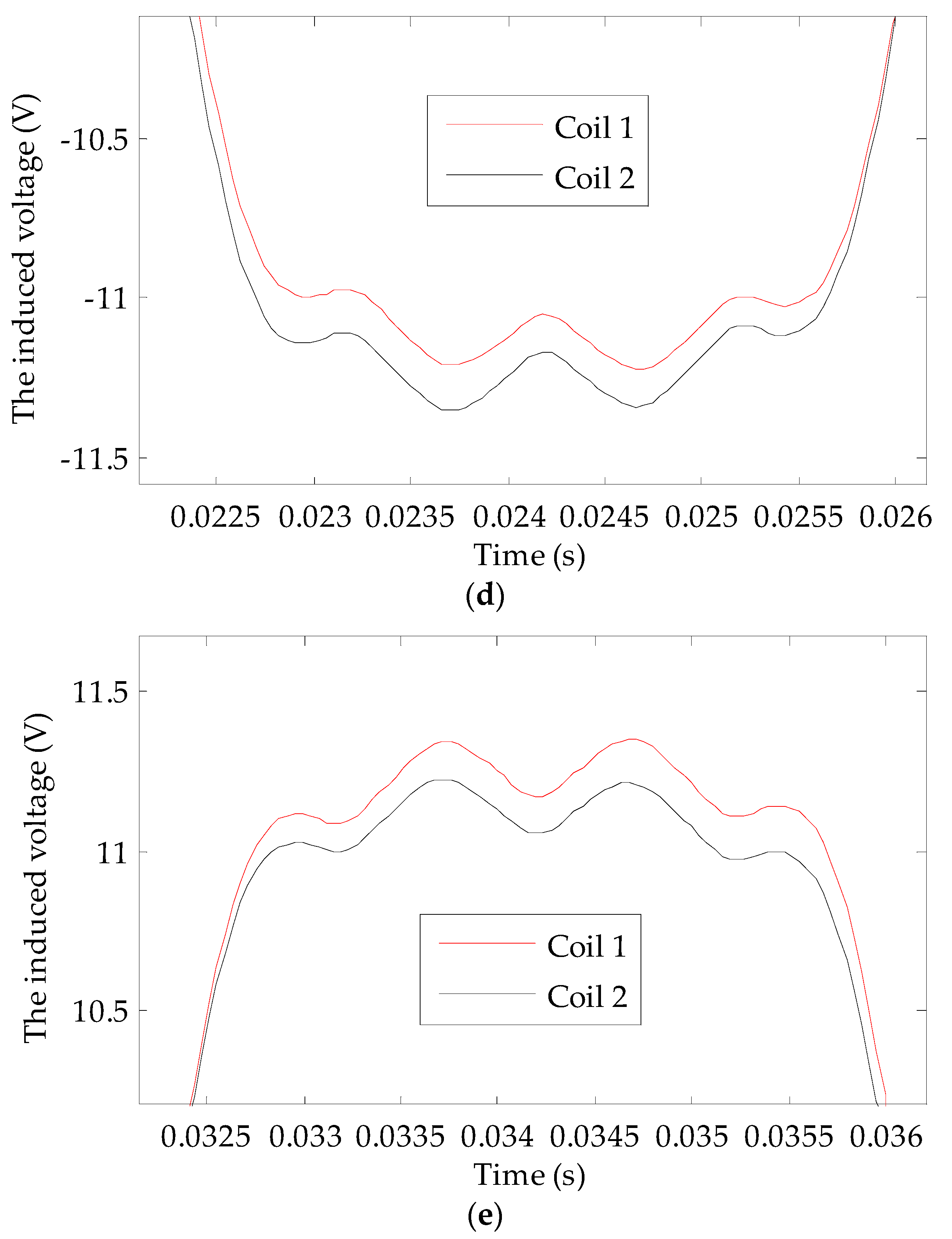
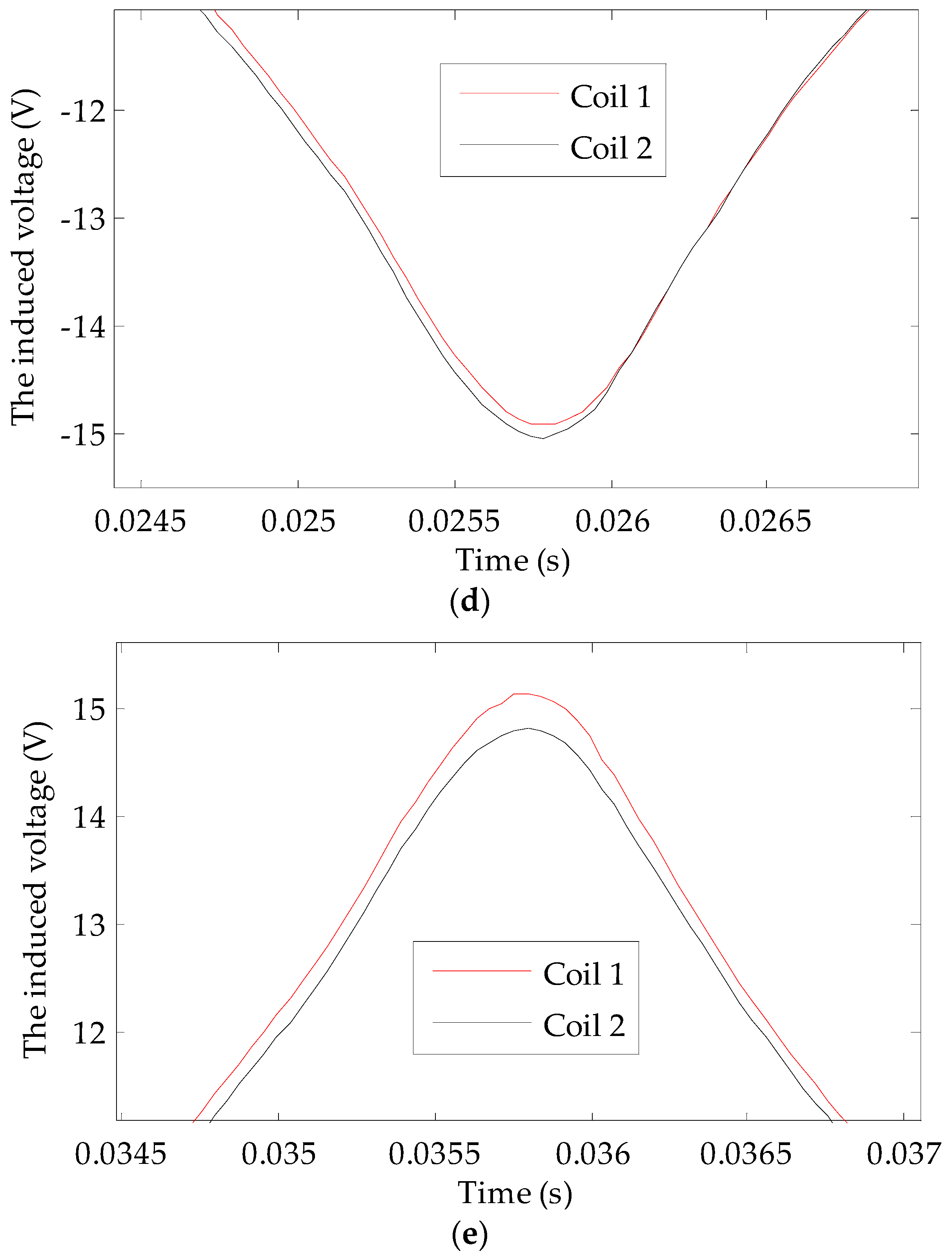
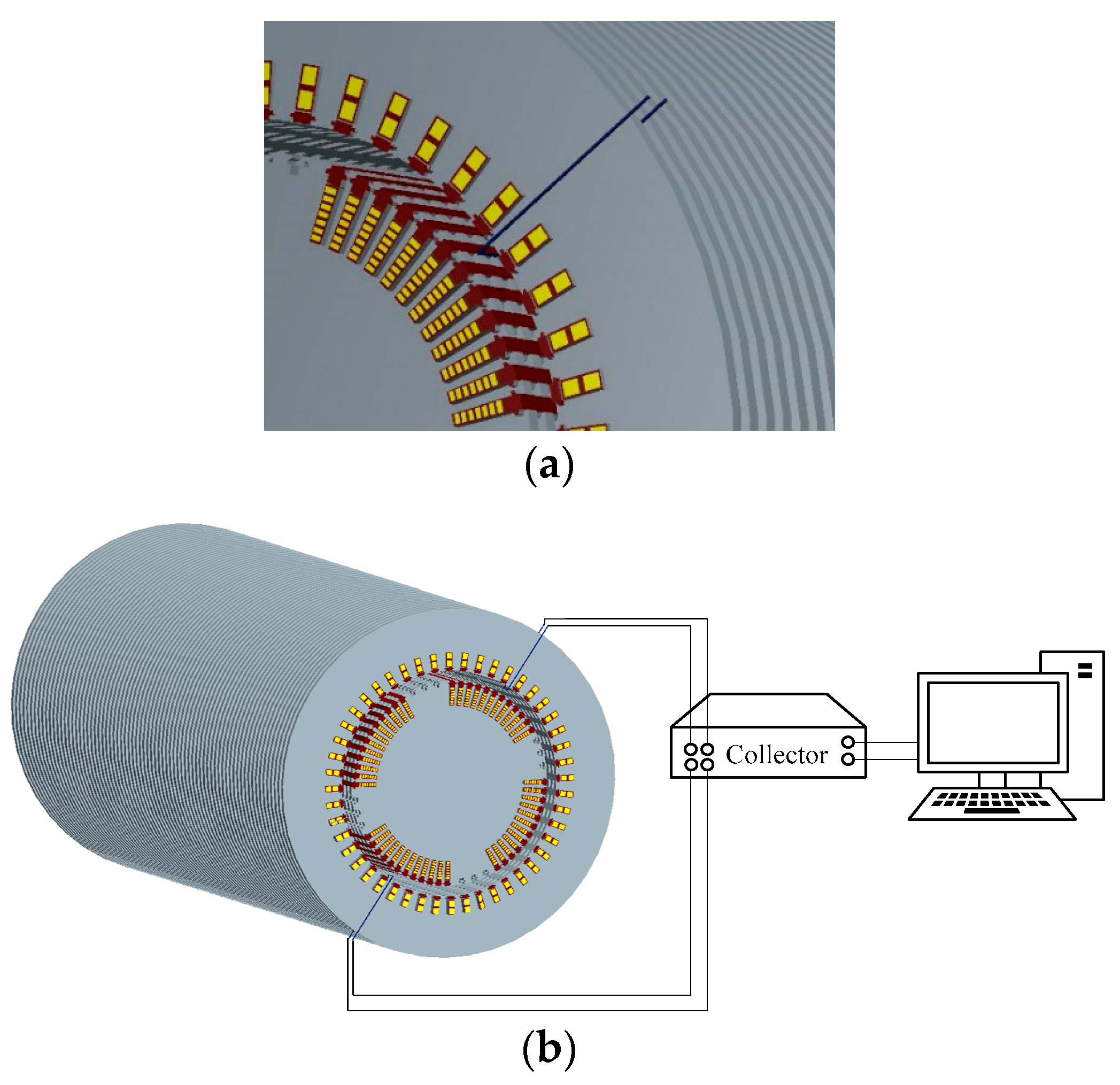
Compared with the magnetic field found with a turn-to-turn short circuit fault in the rotor winding, the frequency of the harmonics that appear in the main magnetic field of a turbo-generator are the same under dynamic eccentricity. It is impossible to judge a turn-to-turn short circuit fault in the rotor winding using the induced voltage spectrum of a single U-shaped coil. Even if these harmonics are detected, it is impossible to determine whether these harmonics are caused by dynamic eccentricity or by a turn-to-turn short circuit in the rotor winding. To address this shortcoming, we propose that two detection coils should be placed symmetrically at a circumferential distance of 180° in the turbo-generator. The principle of this type of detection system is shown in Figure 3.
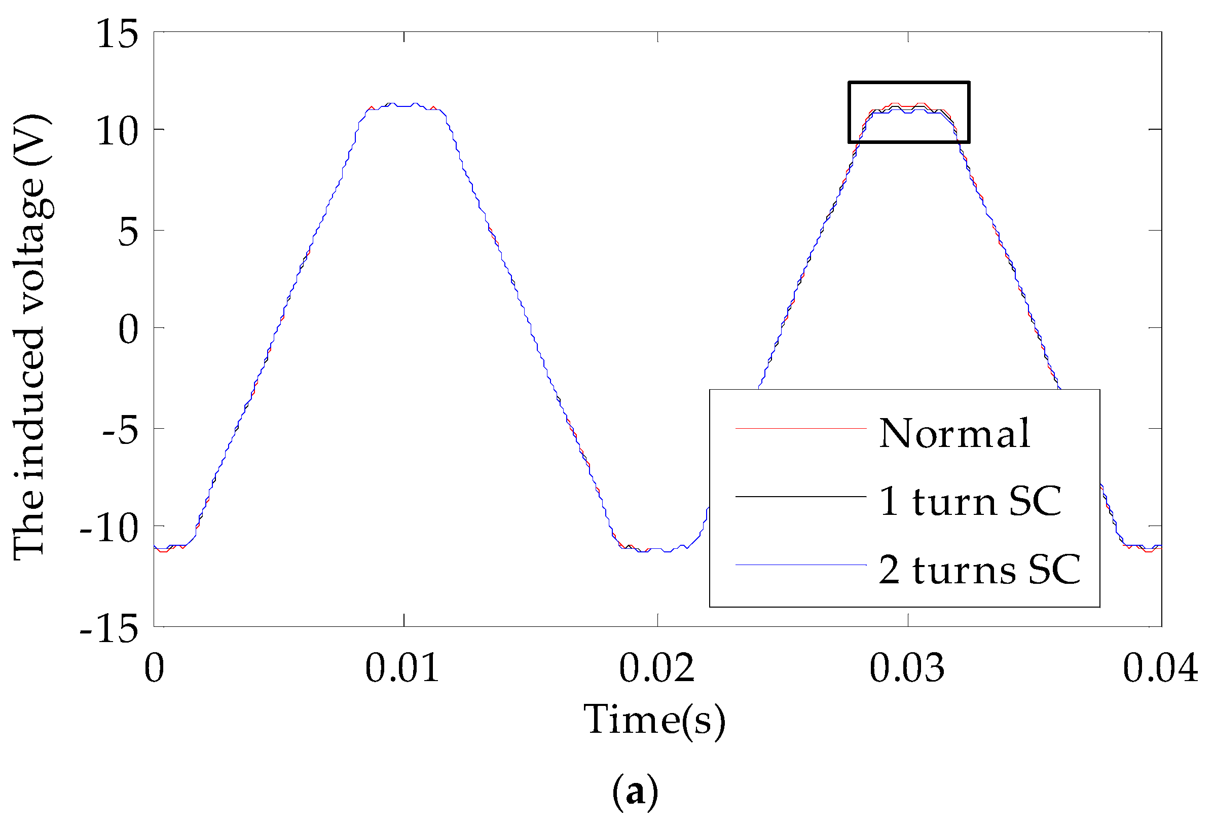
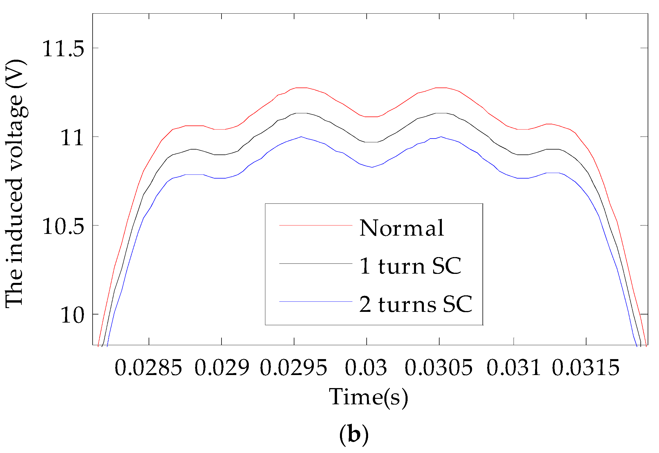
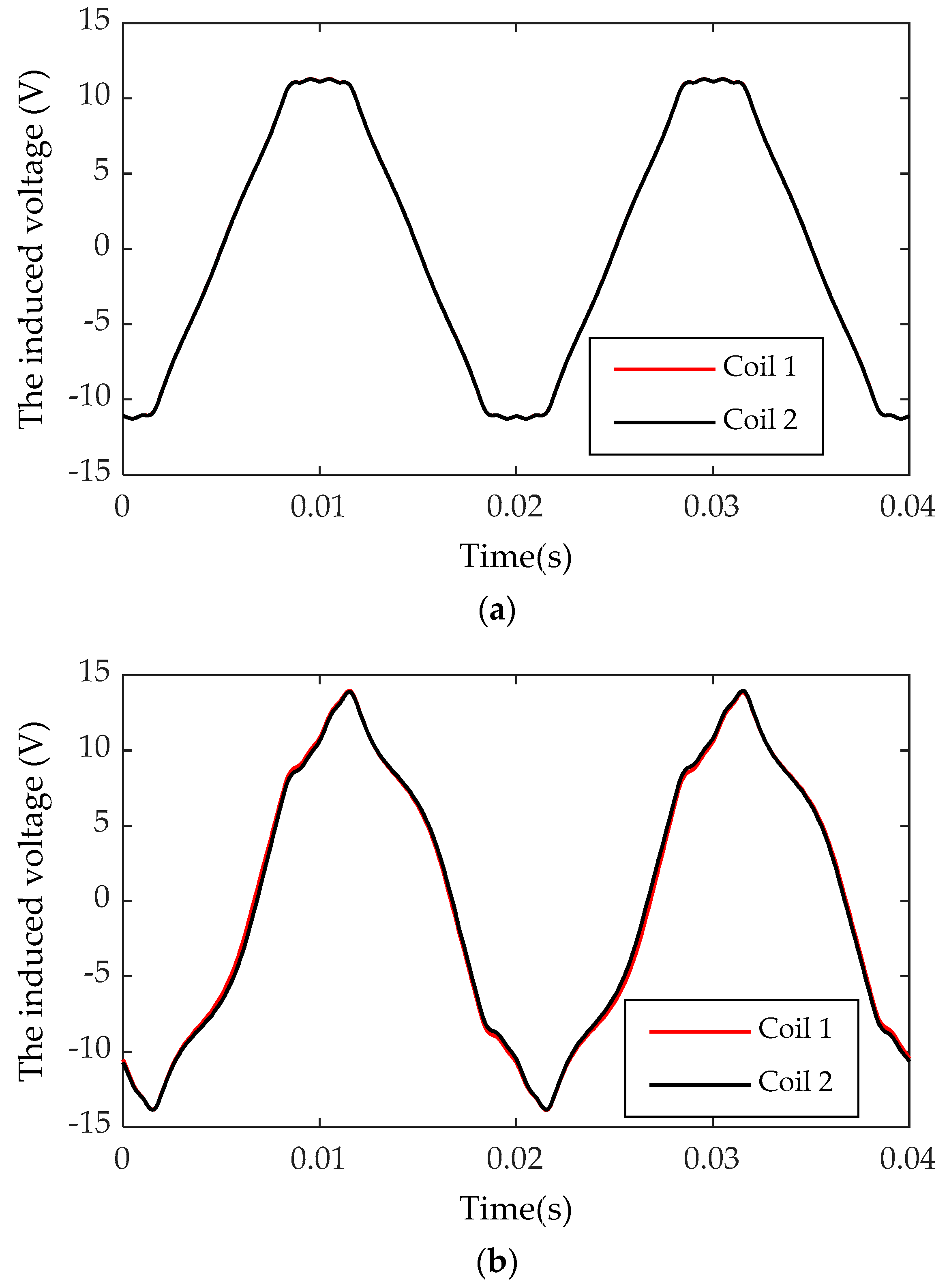
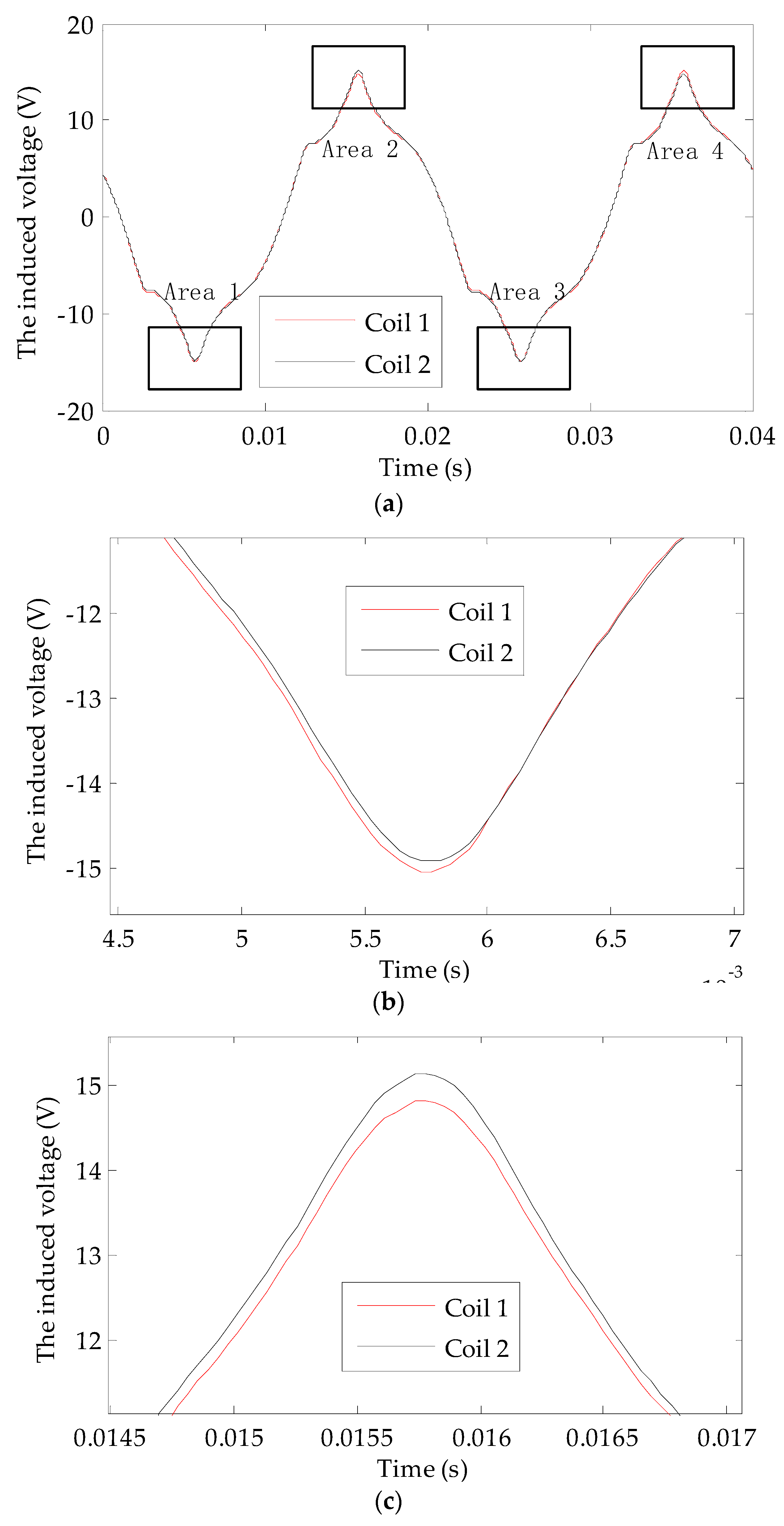
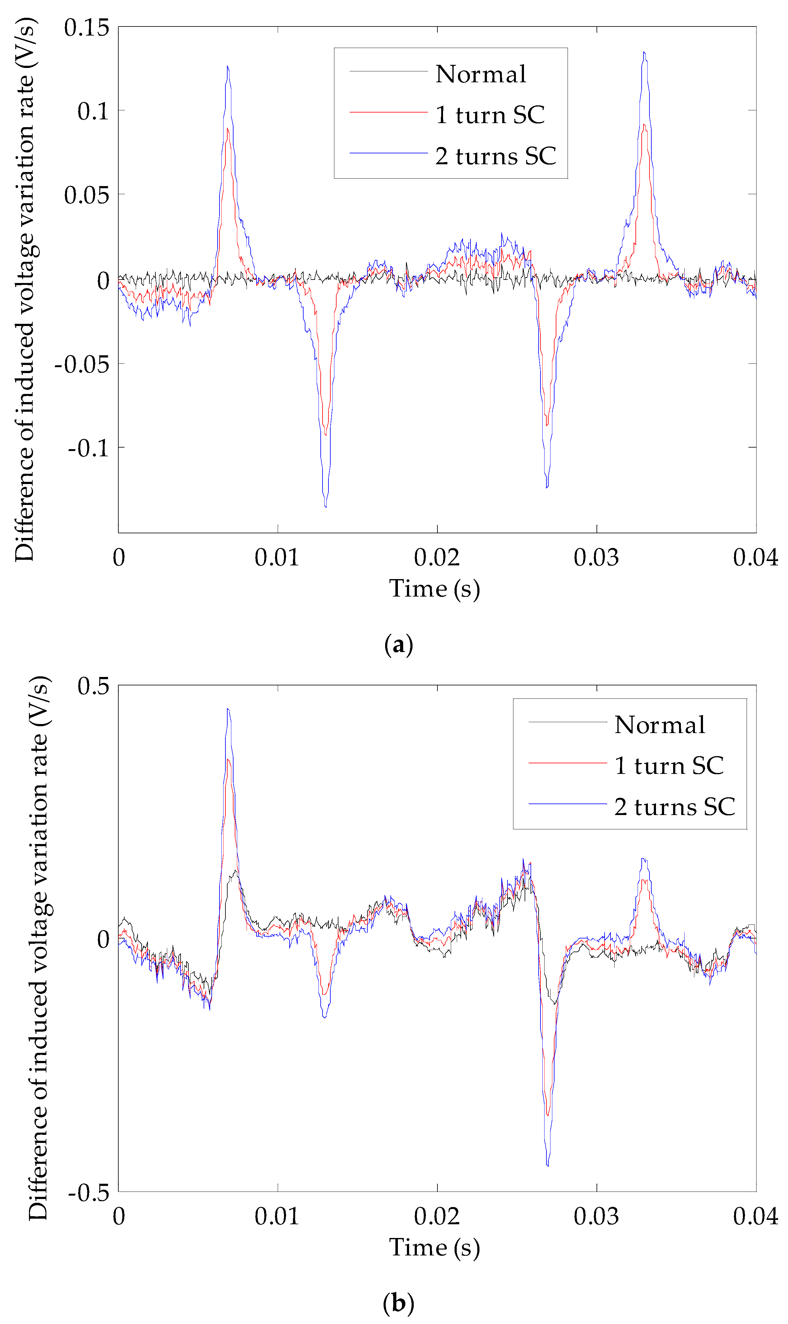
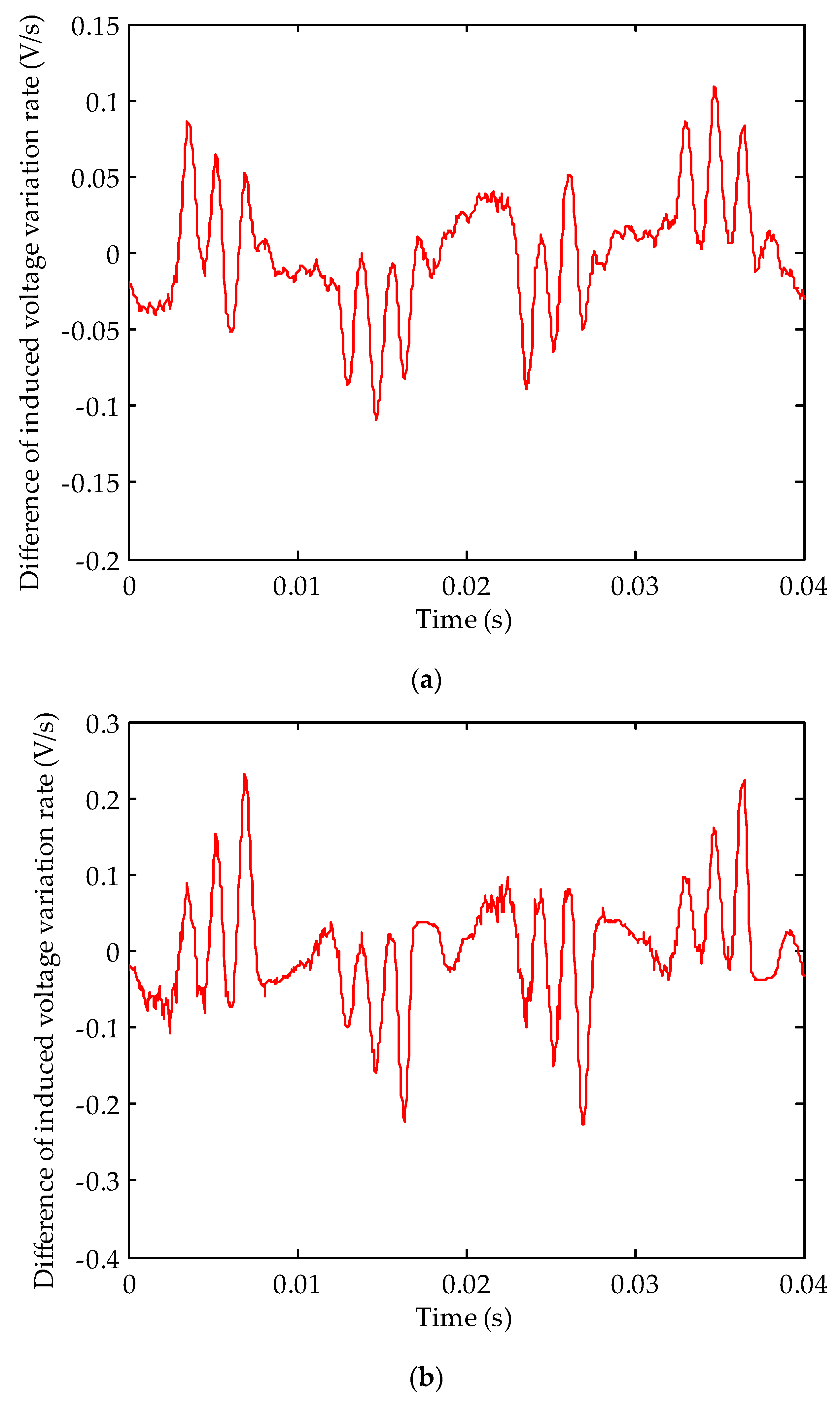
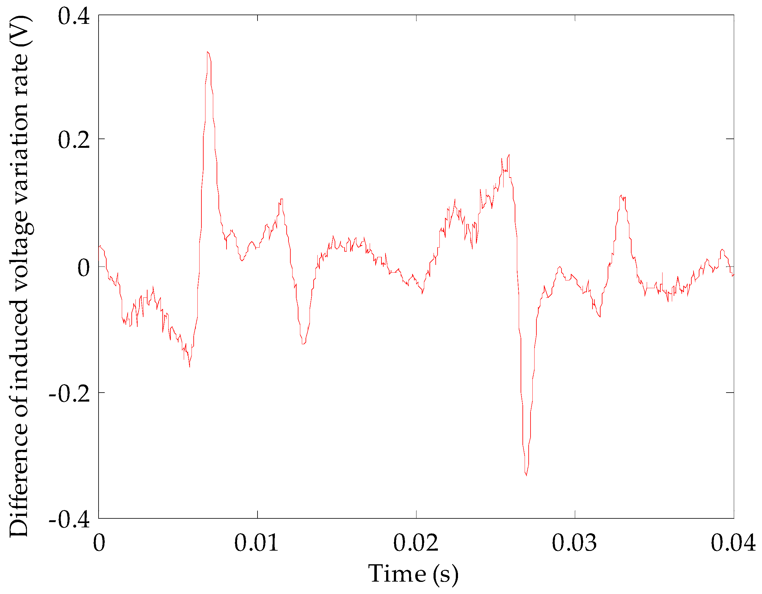
The voltages induced by the U-shaped coils can be expressed as e = BrLv = BrrR, where Br represents the radial component of the air gap flux density at the effective part of U-shaped coil, L is the effective part length of the U-shaped coil, v represents the moving speed of the radial magnetic field relative to the effective part of the U-shaped coil;, ωr is the mechanical angular speed of rotor rotation, and R is the distance between the effective part of the U-shaped coil and the center of the rotor. As L, ωr, and R are all constants, the induced voltage waveform of the U-shaped coil is similar to the radial component waveform of gap flux density at the effective part of the coil. Theoretically, during a fully symmetrical state of the turbo-generator air gap magnetic field, the induced voltages of both coils are the same. After decomposition, the harmonics with the faulty characteristics are not included. The result is zero if the induced voltage time domain waveforms of both coils are added together (two-pole generator) or subtracted (four-pole generator). If a turn-to-turn short circuit fault or dynamic eccentricity fault occurs, although the harmonic contents of the induced voltages for both coils are the same, the induced voltages are different due to the different positions of both detection coils. In this case, the voltage time domain waveform is not zero after operation. There is a significant advantage for adopting the use of double coils: the induced voltages of both coils change simultaneously with a change in the turbo-generator’s operating state. Under a normal state, the output voltage waveforms of both coils will always be the same (four-pole generator) or the opposite (two-pole generator); therefore, the double coil method has excellent anti-interference abilities, which helps to reduce the probability of misjudgment.

3. Demonstration with Simulation

3.1. Modeling and Simulation of Normal Operation Conditions

We chose the TA1100-78 turbo-generator as an example, which is produced by the motor factory of DongFang located in DeYang China; and its basic parameters are shown in Table 1. First, the two-dimensional transient electromagnetic field simulation model was built according to the geometric parameters of the turbo-generator. Then, simulation verification work was completed based on the state settings and fault settings shown in Figure 4.
The induced voltage waveforms of both detection coils operating during the normal state of the turbo-generator rotor are shown in Figure 5. Depending on whether the turbo-generator was under no-load or rated load conditions, the induced voltage waveforms from both coils were almost completely coincident.

3.2. Modeling and Simulation of Turn-to-Turn Short Circuit

A scenario was established where a short circuit fault in the rotor winding occurred in slot #3 separately for 0–2 turns. The induced voltage curves of the detection coils are shown in Figure 6 and Figure 7 over one rotation period (0.04 s).
When the faulty magnetic pole sweeps over the detecting coils, the induced voltages in the coils were smaller than when the rotor winding was normal. If more turns short circuited, the voltage dropped considerably. This result occurred whether the turbo-generator was operating under no-load or with a rated load. The fault features did not change with a change in the turbo-generator’s operating condition.
Harmonic analysis was also conducted on the induced voltage in the detecting coils and all the sub-harmonic contents were obtained as shown in Figure 8.
Figure 8 shows that the harmonics at both 25 Hz and 75 Hz in the induced voltage of the detecting coils increased significantly after the occurrence of a turn-to-turn short circuit fault in the rotor winding. This is consistent with the previous theoretical analysis.

3.3. Simulation of a Dynamic Eccentricity Fault

To verify the anti-interference characteristics of the double coil detection method, the induced voltage of the detection coils has to be observed when the dynamic eccentricity fault occurs. When the turbo-generator was under no load, the rotor dynamic eccentricity was set to 1% and the eccentric direction was 45° away from the d axis of the rotor. Then, the induced voltage curves for the No. 1 and No. 2 detection coils were obtained as shown in Figure 9.
Figure 9 shows that the induced voltage curves of both coils no longer coincided after the occurrence of a dynamic eccentricity fault. Within the half cycle, the induced voltage peak of the No. 1 detection coil was higher than that of the No. 2 detection coil. Within the other half cycle, the induced voltage peak of the No. 2 detection coil was higher than that of the No. 1 coil.
The induced voltage of both coils under rated load is shown in Figure 10. Without a dynamic eccentricity fault, the induced voltage waveforms for both coils were symmetrical; after the dynamic eccentricity fault occurred, the induced voltages became asymmetrical. Therefore, the change rule is similar to that under no-load.
By using the induced voltage of a single detection coil as an example, a Fourier decomposition was performed and the resulting spectrum is shown in Figure 11.
Figure 11 shows that the harmonics of both 25 Hz and 75 Hz induced in the U-shaped coil increased after the occurrence of a dynamic eccentricity fault, and these were not specific to the turn-to-turn short circuit fault of rotor winding. Therefore, it is difficult to distinguish the turn-to-turn short circuit fault in the rotor winding from a dynamic eccentricity fault using the amplitudes of the characteristic harmonics. Here, a dynamic eccentricity fault may be accidently judged to be a turn-to-turn short circuit fault in the rotor winding.

3.4. Extraction Method for Turn-to-Turn Short Circuit Characteristics for Rotor Winding

After a turn-to-turn short circuit in the turbo-generator rotor winding occurs, the step amplitude of excitation magnetic field changes at the position of fault slot. The leakage flux of rotor faulty slot will be smaller than that of corresponding normal slot [4]. For a rotor dynamic eccentricity fault, the change in the air gap length for the turbo-generator is asymptotic, so the change in main magnetic field is relatively subtle. It exists without an obvious or sudden change point, and the leakage flux of each slot in the rotor is not much different. The voltage change rate reflects the change details of the main magnetic field more accurately. Therefore, the induced voltages of both coils can be differentiated, and the voltage waveforms can be subtracted after the differential (they could also be added together if the turbo-generator is two-pole) for observing the sudden change points from the differential waveforms. Figure 12 shows the differential curve from the induced voltage change rates for both detection coils when a 0–2-turn short circuit fault occurs in the winding at the slot #3 in a turbo-generator rotor.
Figure 12 shows that after the turn-to-turn short circuit fault in the rotor winding occurred, four obvious pulses appeared in the differential waveform of the induced voltage change rates during one rotation period. There are two positive and two negative pulses, appearing alternately. The time that the pulses appeared was exactly the time when the faulty slot swept over the detection coils.
After comparison, the amplitudes of the positive and negative pulses in the waveform were found to be equivalent under no-load conditions with good symmetry. However, the amplitudes of the pulses in the waveform were no longer equal to a rated load. This was caused by the armature reaction. The magnetic field saturation of two slots of the faulty coils was different due to the armature’s magnetic field and the leakage flux of the rotor slots was affected further. In Figure 12, the increased amplitude of pulses is positively related to the number of short circuit turns. This shows that the severity and development trend of turn-to-turn short circuit faults in the excitation winding can be reflected by the difference in the induced voltage change rates.
One turn of a short circuit fault was set separately in the winding of slot #3, slot #6, and slot #9 on the rotor. The differential curve of the induced voltages for both detection coils is shown in Figure 13.
In Figure 13, when any of the detection coils swept over slots #3#, #6, and #9 of the rotor, there was an obvious pulse on the differential waveform of the induced voltage change rates. There were 12 pulses during one rotation period. This shows that the fault positions and number of faulty slots can still be judged effectively using this method when a turn-to-turn short circuit occurs simultaneously in the winding of multiple slots on the rotor.

3.5. Combined Fault Simulation for a Turn-to-Turn Short Circuit in the Rotor Winding and Dynamic Eccentricity

Using a turbo-generator with rated load as an example, turn-to-turn short circuit faults and dynamic eccentricity faults were set to occur simultaneously in the rotor winding to verify the effectiveness and anti-interference levels of the new method. Here, the turn-to-turn short circuit in the rotor winding occurred in slot #3 with one turn; the degree of dynamic eccentricity was 1%, with an eccentric direction of 0°. The difference in the induced voltage change rates for two the detection coils is shown in Figure 14.
Figure 14 shows that when the turn-to-turn short circuit fault for the rotor winding and dynamic eccentricity fault occurred simultaneously, there were obvious convex points on the differential waveform for the induced voltage change rates for both detecting coils. This corresponded to the faulty slots on the turn-to-turn short circuit, showing that dynamic eccentricity has little effect on the sudden change point in the local magnetic field caused by a turn-to-turn short circuit. Dynamic eccentricity does have a certain influence on the harmonics of the main magnetic field of the turbo-generator. Therefore, the turn-to-turn short circuit fault in the rotor winding can still be detected effectively using the new detection method.

4. Conclusions

In this article, the characteristics of turn-to-turn short circuit faults in turbo-generator rotor windings were analyzed. For the first time, dynamic eccentricity interference was considered and we proposed that turn-to-turn short circuit faults in rotor winding can be judged in combination with double coils for improving the overall anti-interference performance. Our conclusions are as follows:
(1)
Two U-shaped detection coils were installed separately at two positions on the stator yoke of the turbo-generator at an interval of 180°. The fault position and short circuit degree of a turn-to-turn short circuit in the rotor winding can be judged exactly using the difference in the induced voltages from the coils.
(2)
The interference from dynamic eccentricity faults can be effectively eliminated using the double coil detection method. In the case of combined faults (i.e., a turn-to-turn short circuit and dynamic eccentricity), the turn-to-turn short circuit fault can be still located exactly.
(3)
The double-coil detection method can be used to determine whether there is a turn-to-turn short circuit fault in in the turbo-generator rotor winding, and can also be used as a detection sensor for turbo-generator dynamic eccentricity faults. This means that the method can also assist in judging dynamic eccentricity faults and have a good detection effect for slight eccentricity.

Author Contributions

Y.W. and G.M. supervised all process; Y.W. and G.M. implemented simulation, analyzed the data and checked paper format.

Funding

This research was funded by Natural Science Foundation of Hebei Province, grant number E2016502031

Acknowledgments

Thanks to data support provided by China General Nuclear Power Group. Thank State Key Laboratory of Alternate Electrical Power System with Renewable Energy Sources for providing the laboratory.

Conflicts of Interest

The authors declare no conflict of interest.

References

  1. Zhang, Z.; Liu, S.; Yao, S. Fault Analysis and Diagnosis of Large Generator Rotor; China Electric Power Press: Beijing, China, 2011. [Google Scholar]
  2. Hao, L.; Wu, J.; Zhou, Y. Model of the electromagnetic torque of non-salient-pole synchronous machines with interturn short circuit in field windings. IEEE Trans. Energy Convers. 2015, 30, 110–121. [Google Scholar]
  3. Wu, Y.; Ma, M. Inter Turn Short Circuit of Excitation Winding in Synchronous Generators and Its Diagnosis Method; China Electric Power Press: Being, China, 2018. [Google Scholar]
  4. Šašić, M.; Lloyd, B.; Elez, A. Finite element analysis of turbine generator rotor winding shorted turns. IEEE Trans. Energy Convers. 2012, 27, 930–937. [Google Scholar] [CrossRef]
  5. Fišer, R.; Lavrič, H.; Bugeza, M. Computations of magnetic field anomalies in synchronous generator due to rotor excitation coil faults. IEEE Trans. Magn. 2013, 49, 2303–2306. [Google Scholar] [CrossRef]
  6. Li, Y.; Li, H.; Zhao, H. Fault identification method of rotor inter turn short circuit using stator winding detection. Proc. CSEE 2004, 24, 107–112. [Google Scholar]
  7. Wu, Y.; Li, Y. Diagnosis of rotor winding interturn short-circuit in turbine generators using virtual power. IEEE Trans. Energy Convers. 2015, 30, 183–188. [Google Scholar]
  8. Wu, Y.; Ma, Q.; Cai, B. Fault diagnosis of rotor winding inter-turn short circuit for sensorless synchronous generator through screw. IET Electr. Power Appl. 2017, 11, 1475–1482. [Google Scholar]
  9. Wu, Y.; Li, Y.; Li, H. Diagnosis of non-salient pole synchronous generator rotor’s typical faults based on shaft voltage. Trans. China Electrotech. Soc. 2010, 25, 178–184. [Google Scholar]
  10. Hsu, J.S.; Stein, J. Shaft signals of salient-poles synchronous machines for eccentricity and shorted-field-coil detections. IEEE Trans. Energy Convers. 2004, 9, 572–578. [Google Scholar] [CrossRef]
  11. Wu, Y.; Li, Y. Diagnosis of short circuit faults within turbogenerator excitation winding based on the expected electromotive force method. IEEE Trans. Energy Convers. 2016, 31, 706–713. [Google Scholar]
  12. Wu, Y.; Li, Y. Experimental Study of Rotor Inter-Turn Short Circuit Fault Diagnosis in Turbine Generator Based on Characteristic Frequency of End-Leakage-Flux. Trans. China Electrotech. Soc. 2014, 29, 107–115. [Google Scholar]
  13. Hao, L.; Sun, Y.; Qiu, A.; Wang, X. Steady-state calculation and online monitoring of interturn short circuit of field windings in synchronous machines. IEEE Trans. Energy Convers. 2012, 27, 128–138. [Google Scholar] [CrossRef]
  14. Wu, Y.; Ma, M.; Li, Y. A new detection coil capable of performing online diagnosis of excitation winding short-circuits. IEEE Trans. Energy Convers. 2018, 33, 106–115. [Google Scholar]
  15. Penman, J.; Jiang, H. The detection of stator and rotor winding short circuits in synchronous generators by analysing excitation current harmonics. In Proceedings of the International Conference on Opportunities and Advances in International Electric Power Generation, Durham, UK, 18–20 March 1996; pp. 137–142. [Google Scholar]
  16. Iamamura, B.A.T.; Le Menach, Y.; Tounzi, A.; Sadowski, N.; Guillot, E. Study of Static and Dynamic Eccentricities of a Synchronous Generator Using 3-D FEM. IEEE Trans. Magn. 2010, 46, 3516–3519. [Google Scholar] [CrossRef]
Figure 1. End structure of the excitation winding.
Energies 12 01378 g001
Figure 2. Waveform of excitation magneto motive force. Ff is the excitation magneto motive force in a stepped wave after a turn-to-turn short circuit; Ff’ is the excitation magneto motive force of the stepped wave when the winding is normal.
Energies 12 01378 g002
Figure 3. Schematic diagram of the detection system: (a) Structure of a single coil; (b) Online detection system.
Energies 12 01378 g003
Figure 4. Schematic diagram of the simulation.
Energies 12 01378 g004
Figure 5. Induced voltage curve of both detection coils: (a) no-load; (b) rated load.
Energies 12 01378 g005
Figure 6. Induced voltage curve for the No. 1 detection coil with different short circuit degrees in slot #3 under no-load conditions: (a) Global map; (b) Local map. Where, SC is the abbreviation of Short Circuit.
Energies 12 01378 g006aEnergies 12 01378 g006b
Figure 7. Induced voltage curve for the No. 1 detection coil with different short circuit degrees in slot #3 under rated load conditions: (a) global map; (b) local map.
Energies 12 01378 g007
Figure 8. Induced voltage spectrum for detection coils with different short circuit degrees: (a) no-load; (b) rated load.
Energies 12 01378 g008
Figure 9. Induced voltage curves for both detection coils at the dynamic eccentricity of 45° under no-load: (a) global map; (b) local map 1; (c) local map 2; (d) local map 3; (e) local map 4.
Energies 12 01378 g009aEnergies 12 01378 g009b
Figure 10. Induced voltage curves for both detection coils at a dynamic eccentricity of 45° with rated load: (a) global map; (b) local map 1; (c) local map 2; (d) local map 3; (e) local map 4.
Energies 12 01378 g010aEnergies 12 01378 g010b
Figure 11. Induced voltage spectrogram for detection coils: (a) no-load; (b) rated load.
Energies 12 01378 g011aEnergies 12 01378 g011b
Figure 12. Difference in the induced voltage change rates for both detection coils with different short circuit degrees in winding slot #3: (a) no-load; (b) rated load.
Energies 12 01378 g012
Figure 13. Difference in induced voltage change rates for both detection coils with a one-turn short circuit occurring separately in slots #3#, #6, and #9: (a) no-load; (b) rated load.
Energies 12 01378 g013
Figure 14. Difference in the induced voltage change rates for both detection coils with rated load when the dynamic eccentricity was 1% and a 1-turn short circuit occurred.
Energies 12 01378 g014
Table 1. Parameters of TA1100-78 turbo-generator.
ParameterValue
Rated voltage (V)24,000
Rated current (A)30,739
Rated power (MW)1150
Rated excitation current (A)5795
No-load rated excitation current (A)2189
Rated rotary speed (rpm)1500
Frequency (Hz)50
Phase number3
Number of stator slots48
Number of rotor slots48
Exciting modeBrushless excitation
Length of air gap (mm)96
Connection way of rotor windingY-Y
Number of pole pairs2

