Article

Research on the Operation Control Strategy of a Low-Voltage Direct Current Microgrid Based on a Disturbance Observer and Neural Network Adaptive Control Algorithm

School of Electrical Engineering, Northeast Electric Power University, Jilin 132012, China
*
Author to whom correspondence should be addressed.
Energies 2019, 12(6), 1162; https://doi.org/10.3390/en12061162
Submission received: 26 February 2019 / Revised: 23 March 2019 / Accepted: 25 March 2019 / Published: 25 March 2019

Abstract

:
Low-voltage direct current (DC) microgrid based on distributed generation (DG), the problems of load mutation affecting the DC bus under island mode, and the security problems that may arise when the DC microgrid is switched from island mode to grid-connected mode are considered. Firstly, a DC bus control algorithm based on disturbance observer (DOB) was proposed to suppress the impact of system load mutation on DC bus in island mode. Then, in a grid-connected mode, a pre-synchronization control algorithm based on a neural network adaptive control was proposed, and the droop controller was improved to ensure better control accuracy. Through this pre-synchronization control, the microgrid inverters output voltage could quickly track the power grid’s voltage and achieve an accurate grid-connected operation. The effectiveness of the algorithms was verified by simulation.

1. Introduction

When the load demand is similar, distributed generation (DG) has reduced the power loss caused by long-distance transmission compared with centralized generation, and has the advantage of a high-energy utilization rate [1]. Microgrid can be divided into direct current (DC) microgrid, alternating current (AC) microgrid and AC/DC hybrid microgrid according to the structures [2,3]. With the development of power electronic technology, AC power must supply to a low-voltage DC load through rectifying equipment. The harmonic current introduced by a large amount of power conversion greatly affects the quality of power. In order to solve this problem, the load must be equipped with a power factor compensation circuit, which will lead to increased costs [4]. So far, preliminary research on the system structure, load compatibility, energy saving assessment and power quality of low-voltage DC microgrids show that low-voltage DC microgrids can be compatible with most low-voltage loads and can effectively control the transient process of a power system, especially in a low-voltage DC microgrid connected by a large number of DGs. Compared to an AC microgrid, a low-voltage DC microgrid has the advantages of reducing power loss, facilitating the access of DGs and loads, enhancing power supply continuity and reliability as well as improving power quality [5].
As the main force of new energy power generation technology, photovoltaic power generation has uncertainties and randomness. Therefore, microgrids are usually equipped with energy storage systems. When the output of other DGs is unstable or the system load changes, the power balance of the microgrids can be maintained by charging and discharging capacity of the energy storage systems [6]. Reference [7,8] proposes a concept of stochastic model predictive control (MPC), which was applied to the optimization problem of renewable energy to deal with the uncertainty and variability issues of renewable energy resources. Experimental results show that the algorithm improves the robustness and resiliency of the prediction error of renewable energy. At present, some scholars have proposed the master-slave control mode in the study of microgrid control. Due to the decentralization of microgrid converters, the master-slave controllers rely on communication systems to communicate. Once communication fails, the microgrid will not function normally [9]. Reference [10] proposes a control strategy, which takes account of the demand side response and flexible participation of an energy storage system, and eliminates the constraints on elastic demand by two-stage iteration. However, the control of the algorithm is complex, the computational complexity is large and it is not easy to practice in engineering. At the same time, additional communication systems are needed. Reference [11] designs a multi-mode operation control method according to different operation conditions. It coordinates DGs and energy storage systems to achieve an autonomous smooth transition without communication lines, but leads to large frequency deviation in the switching process. Reference [12] studies a charging station for a photovoltaic electric vehicle, which uses a bidirectional AC/DC converter as a central controller to regulate the DC bus voltage. However, the energy storage system and photovoltaic (PV) unit do not participate in system energy management, so the dynamic response of the system is slow and its reliability is low. Reference [13] introduces the concept of virtual inertia and proposes a method of incorporating a short-term energy storage device. In order to improve the stability margin of the system, the energy storage device is used as virtual inertia to provide or absorb short-term power to the system when disturbances occur, so as to improve the transient stability of the power system. The experimental results show that when virtual inertia is introduced, the stability limit of the system is effectively improved. Reference [14] proposes a method of integrating energy storage system (ESS) with renewable energy sources (RES), which is based on stochastic, adaptive and dynamic control approach to minimize the daily operation cost of management system, and solve the uncertainty issues of renewable energy power. Model predictive control (MPC) technology is used to deal with the change of RESS power [15]. However, its control method is complex, and it is not easy to achieve real-time control, so it does not achieve high practicability. Reference [16] proposes an optimal control management system, which can effectively avoid the conflict between device controllers and restrain the negative effects of the transient state on power supply quality and continuity. However, the proposed system model does not include the energy storage system and DG, and does not study the island state.
Therefore, in this paper, a low-voltage DC microgrid with photovoltaic and energy storage systems is established, and a DC bus control algorithm based on the disturbance observer (DOB) is proposed for its island operation mode. The algorithm takes the DC bus power, voltage, battery output voltage and current as control signals, and takes the DC bus state and battery output state into account, comprehensively. Under the sudden change of a system load, the DC bus can still achieve power balance and voltage stability. The DOB solves the problem of excessive voltage deviation in the regulation process. The algorithm does not need the participation of a communication system, it simplifies the structure of the control system, reduces cost, improves autonomy, anti-interference and stability.
When the power grid needs to utilize the energy of the microgrid more effectively, the microgrid needs to be switched to the grid-connected operation state. In the process of a grid-connected operation, due to the deviation of the amplitude, frequency and phase of the output voltage of the inverters from that of the power grid, if the microgrid is directly connected to the grid, a huge impulse current will be generated, which will greatly damage the stable operation of the microgrid and the power grid [17]. Therefore, before implementing the grid-connected operation, the pre-synchronization control of the microgrid inverters must be carried out to realize real-time tracking of the microgrid inverters output voltage to the power grid voltage. Because the grid-connected control algorithm based on traditional phase-locked loop (PLL) has the disadvantages of long synchronization time, low efficiency and easy to generate fluctuating voltage and impulse current [18], a pre-synchronization control algorithm based on a neural network adaptive control structure is proposed in this paper. The cerebellar model articulation controller (CMAC) neural network and traditional proportion-integral-derivative (PID) composite adaptive algorithm is used, which has the advantages of a fast learning speed, high control timeliness, a smooth convergence process and an insensitive sequence of learning data on the premise of guaranteeing approximation of non-linear functions. It enables the output voltage of the inverter to track the voltage of the power grid quickly and accurately, and realizes the safe switching from island mode to grid-connected mode.

2. Control Strategy of Photovoltaic and Energy Storage System

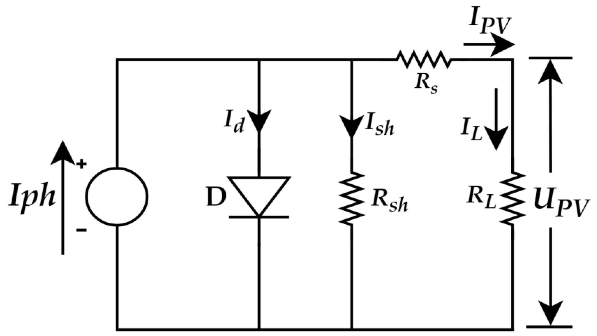
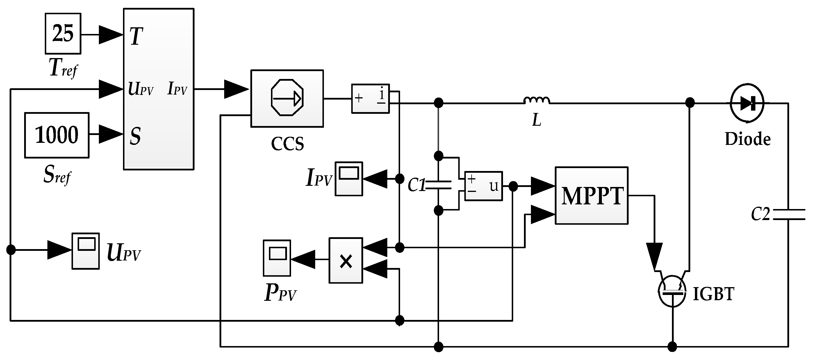
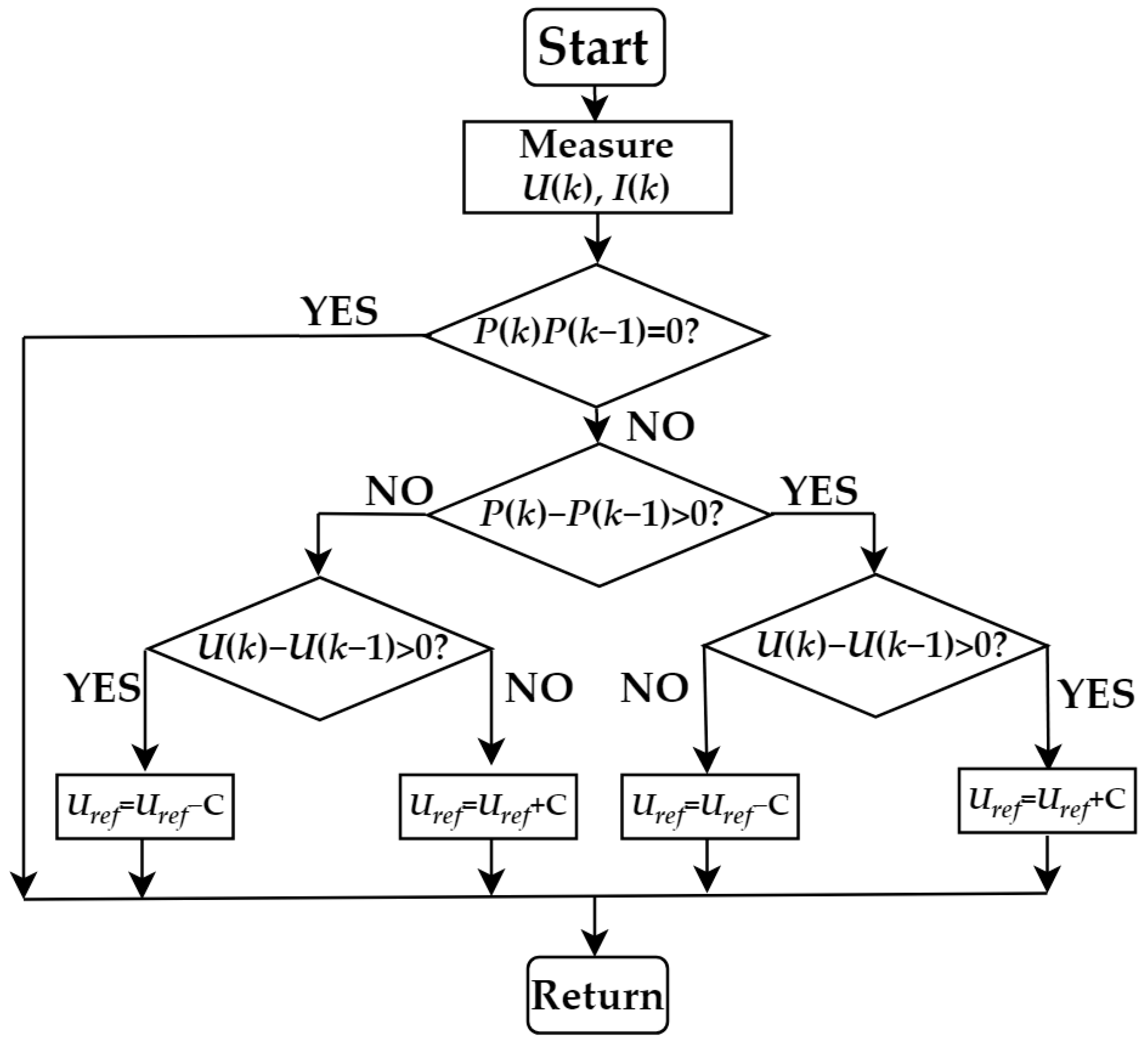
2.1. Photovoltaic Cell Model and Control Strategy

Photovoltaic cell is a DG that uses photovoltaic effect to convert light energy into electricity [19]. A photovoltaic cell is composed of three parts: Photovoltaic current source, diode, series and parallel resistances. The typical equivalent circuit of a photovoltaic cell is shown in Figure 1.
The formula for calculating the output current of a photovoltaic cell is as follows:
I P V = I p h I d [ exp ( U P V + I · R S n K T / q ) 1 ] U P V + I · R S R s h
Among them, Iph is the photogenerated current, Id is the reverse saturated current of the diode, UPV is the output voltage of the battery, RS and Rsh are the series resistance and parallel resistance of the battery respectively, n is the ideal factor of the diode, K is the Boltzmann constant (1.381 × 10⁻²³ J/K), T is the absolute temperature of the photovoltaic panel and q is quantity of electric charge (1.6 × 10⁻¹⁹ C) [20]. The simulation model of a photovoltaic cell is established in Matlab/Simulink, as shown in Figure 2.
Since the output voltage of a photovoltaic cell is low, the photovoltaic cell is connected with the DC bus by a boost circuit. The control mode of a boost circuit is Maximum Power Point Tracking (MPPT) method based on the disturbance observation method. The basic principle of the disturbance observation method is to add a small disturbance to the voltage, calculate the variation of the output voltage and power and compare it with the previous state. If the output power increases or decreases synchronously with the voltage value, the disturbance direction is correct and the maximum power tracking can be achieved by continuously disturbing the voltage [21]. The MPPT control flow chart of the disturbance observation method is shown in Figure 3 [22]. Among them, U(k) and U(k−1) are the current and previous output voltage of the photovoltaic cell respectively, I(k) is the current output current, P(k) and P(k−1) are the current and previous output power of the photovoltaic cell, respectively, Uref is the reference voltage of the photovoltaic cell and C is the step-size setting value.

2.2. Control Algorithm of a Photovoltaic and Energy Storage System

In the DC microgrid composed of photovoltaic cells, energy storage batteries and DC loads, energy storage batteries play the role of stabilizing the DC bus voltage and balancing the power allocation of each unit [23,24]. When the system load changes abruptly, the power of the microgrid system is unbalanced, and the DC bus power and bus voltage fluctuate sharply. In view of the shortcomings of the existing methods for suppressing load disturbances in the DC microgrid, a DC bus control algorithm based on DOB is proposed in this paper. The algorithm regards the change of the DC bus voltage caused by load change as an external disturbance. The DOB estimates the disturbance of the DC bus voltage. Feedforward compensation is used to dynamically eliminate the influence of the disturbance on the DC bus voltage. The parameter design of the algorithm is simple and easy to implement in engineering. It can not only improve the anti-disturbance performance of the control system against a load disturbance, but it also does not affect the following performance of the original control system. The control algorithm is shown in Figure 4.
Among them, Pdc and Udc represent the actual power and voltage of the DC bus, respectively, Ub and Ib represent the output voltage and current of energy storage system, respectively. The algorithm takes the DC bus power and voltage, battery output voltage and current as control signals, without the participation of a communication system.
The basic principle of DOB is that the difference between the output of the actual model and the reference model caused by the external disturbance of the controlled object and its parameter changes, is regarded as the system disturbance. DOB estimates the output difference caused by the disturbance in real time and feedforward compensates it to the input, so as to actively suppress the influence of the disturbance [25]. Its control structure is in Figure 5.
Among them, the dotted frame part is DOB, R(s) is the system input, Y(s) is the system output, C(s) is the transfer function of PI controller, c(s) is the PI controller output, u(s) is the intermediate operation variable, G(s) is the actual model of the controlled object, Gn(s) is the reference model of the controlled object, d(s) is the equivalent disturbance of the system, d ^ ( s ) is the disturbance compensation estimated by the DOB and Q(s) is the low-pass filter.
As can be seen from the figure above, the transfer function of output Y(s) without the DOB is as follows:
Y ( s ) = Φ R ( s ) R ( s ) + Φ d ( s ) d ( s )
Without the DOB, ΦR(s) and Φd(s) are transfer functions of input R(s) and disturbance d(s) to output Y(s), respectively.
{ Φ R ( s ) = C ( s ) G ( s ) 1 + C ( s ) G ( s ) Φ d ( s ) = G ( s ) 1 + C ( s ) G ( s )
After adding the DOB, the output of the system is as follows:
{ Y ( s ) = Φ R ( s ) R ( s ) + Φ d ( s ) d ( s ) Φ R ( s ) = C ( s ) G ( s ) G n ( s ) G n ( s ) ( 1 Q ( s ) + C ( s ) G ( s ) + G ( s ) Q ( s ) ) Φ d ( s ) = G ( s ) G n ( s ) ( 1 Q ( s ) ) G n ( s ) ( 1 Q ( s ) + C ( s ) G ( s ) + G ( s ) Q ( s ) )
After adding DOB, ΦR′(s) and Φd′(s) are transfer functions of input R(s) and disturbance d(s) to output Y(s), respectively.
When Q(s) = 1 in the middle and low frequency bands, the disturbance compensation can be as follows:
d ^ ( s ) = ( 1 G n ( s ) G ( s ) ) R ( s ) + d ( s )
From the above formula, when G(s) = Gn(s), d ^ ( s ) = d(s), ΦR(s) = ΦR′(s), Φd′(s) = 0, it shows that the disturbance compensation estimated by the DOB can completely offset the influence of parameter changes and external disturbances on the system, and has good robustness.
In a high frequency band, if Q(s) = 0, then ΦR(s) = ΦR′(s), Φd′(s) = Φd(s). At this time, the output of the system is the same as that without the DOB, and the control performance of the DOB disappears.
Let the frequency band of low pass filter Q(s) be fQ. When ffQ, Q ≈ 1, and when f > fQ, Q ≈ 0. Therefore, the design of Q(s) is the key point in the design of the DOB. The order of Q(s) must be no less than that of Gn(s) [26]. Since the transfer function of the generalized controlled object is a second-order inertial link, the second-order low-pass filter is chosen to satisfy the above characteristics. The DOB design is as follows:
Q ( s ) = 1 ( τ s + 1 ) 2
Q ( s ) G n ( s ) 1 = L f n C f n s 2 + R f n C f n s + 1 k P W M ( τ s + 1 ) 2
Among them, τ is the filter time constant, Lfn, Cfn and Rfn are inductance, capacitance and resistance of filter, respectively.

3. Control Strategy for a Grid-Connected Operation of the Low-Voltage DC Microgrid

3.1. Droop Control Strategy

On the basis of bus voltage stability of the DC microgrid, the voltage source inverter control system was adopted for its grid-connected operation. The structure of the system is in Figure 6.
The main circuit of the system is a three-phase full-bridge voltage source inverter [27]. The LC filter is connected to the output side of the inverter to filter high-order harmonics [28]. This paper adopted a droop control strategy to control the inverter. Droop control is a method to control the inverter by simulating the droop characteristics of synchronous generators in traditional power systems [29]. The control part of the system included power calculation, droop control, voltage and a current double loop control. Firstly, the output voltage and current of the inverters were collected to calculate the output power of the inverters. Then, the reference values of the output voltage amplitude and frequency were obtained by droop control and the reference voltage was obtained by voltage synthesis link as the input reference of the voltage and current double loop control link. Finally, the Sinusoidal Pulse Width Modulation (SPWM) signal was generated by adjusting the voltage and current double loop control link to control the inverter.
Droop control strategy can be expressed as:
{ ω = ω n m ( P P n ) U = U n n ( Q Q n )
Among them, ω and U are the angular frequency and amplitude of the actual output voltage, ωn and Un are the angular frequency and amplitude of the rated output voltage of the inverter, m and n are the active power droop coefficient and reactive power droop coefficient, P and Q are the actual output active power and reactive power and Pn and Qn are the rated output active power and reactive power of the inverters, respectively.
The traditional droop control was suitable for the case where the lines impedance of the microgrid was inductive. However, when the line impedance of the microgrid is large, it will be difficult for the traditional droop control to achieve the power sharing of the inverters and reduce the coupling degree of active and reactive power transmission [28]. For this reason, virtual impedance was added to the voltage and current double loop control link in the traditional droop control to improve the inductance of line impedance, as shown in Figure 7.
Among them, Uref and U are reference voltage and output voltage, i0 is load current, Lf and Cf are filter inductance and filter capacitance, Gu(s) and Gi(s) are transfer functions of the voltage outer loop and current inner loop respectively, and KSPWM is the pulse width modulation proportional coefficient of inverters. The virtual impedance Zv can be calculated from the above figure as follows:
Z v = Δ U i 0 ( Z l + Z 0 ) G
Zl is the line impedance, Z0 is the equivalent output impedance of the inverter and G is the equivalent voltage transfer function of the inverter. Due to the introduction of the virtual impedance Zv, the line resistance-inductance ratio is expressed as follows:
r = R X = R l R v s ( L l + L v )
Among them, Rv and Rl are virtual resistance and line resistance, Lv and Ll are virtual inductance and line inductance, respectively. According to the change of angle frequency and amplitude of the inverter output voltage, m, n and r were adjusted. The improved droop control algorithm is expressed as follows:
{ ω = ω n m P + n U r | Z v + Z l | Q U = U n m U r | Z v + Z l | P n Q

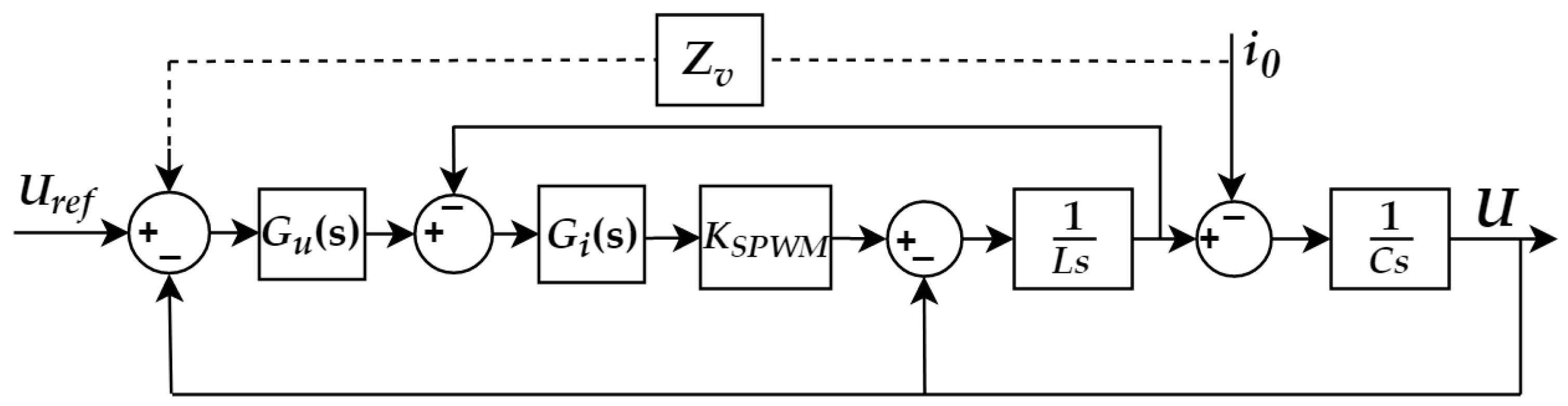
3.2. Grid-Connected Operation Control Strategy of the Microgrid

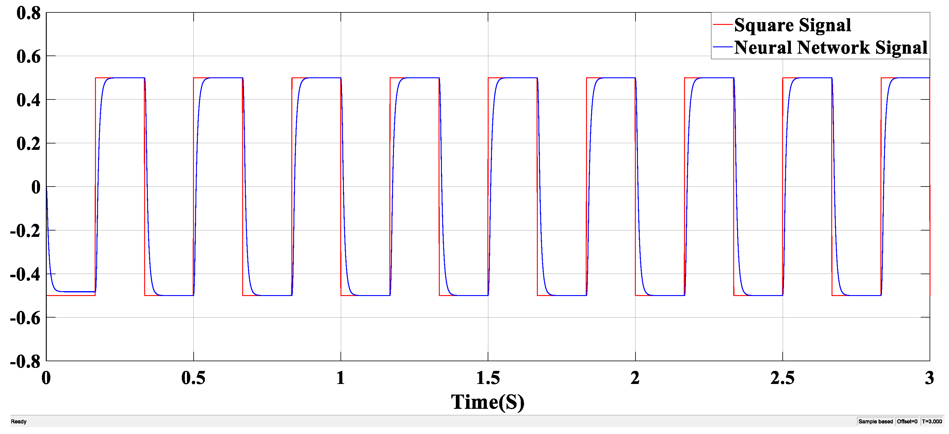
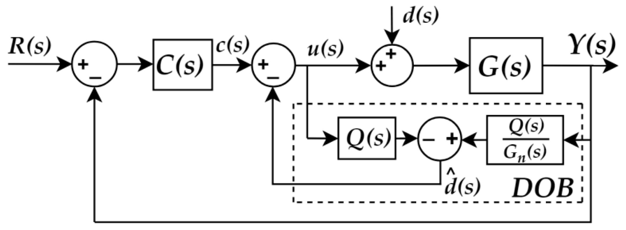
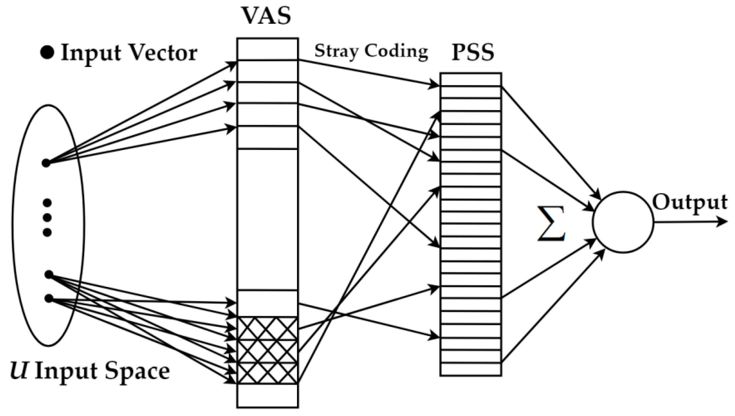
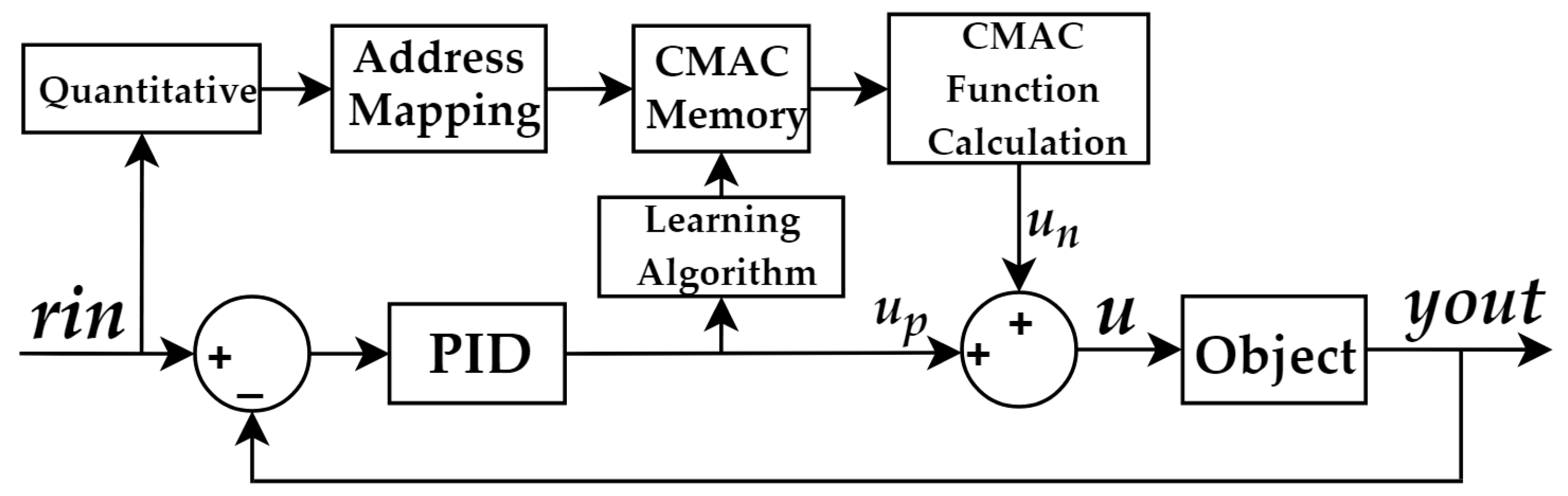
3.2.1. Neural Network Adaptive Control Algorithm

When the power grid needs to utilize the energy of the microgrid more effectively, it is necessary to parallelize each microgrid with the power grid. At this time, the microgrids works in grid-connected operation mode. When the microgrid and the power grid operate independently, their voltage amplitude, frequency and phase may not be the same. If the grid-connected operation was carried out directly at that time, it will cause a huge impulse current, damage power system equipment and even cause the paralysis of the whole power grid [30]. Therefore, it is necessary to control the parameters of the microgrid voltage to track the power grid voltage completely, in order to achieve a safe grid-connected operation [31,32]. Therefore, based on the droop control and neural network adaptive control algorithm, a pre-synchronization control algorithm is proposed in this paper.
CMAC is a table query adaptive neural network which can express complex non-linear functions, and can learn arbitrary multi-dimensional non-linear mapping [33]. Compared with Back Propagation (BP) and Radial Basis Function (RBF) neural networks, CMAC is based on local learning where the information is stored in the local structure, which makes the weight of each correction very small, and on the premise of approaching the non-linear function, it has advantages of a fast learning speed, high control timeliness and insensitive sequence of learning data [34]. The control structure of CMAC is shown in Figure 8.
The CMAC design method was divided into three steps: The first step was quantization and the N-dimensional input space was divided at the input layer. Each input falls into a hypercube unit of the N-dimensional network, for any input in the middle layer, only the output of a few intervals was non-zero, and the number of non-zero intervals was the normalized parameter c. The second step was address mapping. The division remainder method was used, which mapped the input sample to the address of the conceptual memory, and the remainder was used as the address value of the actual memory. The third step was the CMAC output, which mapped the input to the c cells of the actual memory with each cell storing the corresponding weight and the output of the CMAC was the sum of the weights of c actual memory cells [35].
In this paper, CMAC and traditional PID composite adaptive control algorithm is proposed. The structure of the algorithm is shown in Figure 9.
Among them, CMAC implements feedforward control to realize the inverse dynamic model of the controlled object and the traditional PID implements feedback control to suppress the disturbance. At the end of each control cycle of CMAC, the output un(k) was obtained. Compared with the total input u(k) of the system, the weight was corrected, and the learning process began, so that the difference between the total control input and the output of the CMAC was minimized. The total system output was generated by CMAC. The control algorithm can be expressed as follows:
u n ( k ) = i = 1 c w i a i
u ( k ) = u n ( k ) + u p ( k )
Among them, wi is the weight, ai is the binary selection vector, c is the normalized parameter of the CMAC network, un(k) is the output of CMAC and up(k) is the output of traditional PID. The adjustment indexes of CMAC are as follows:
E ( k ) = 1 2 ( u ( k ) u n ( k ) ) 2 · a i c
Δ w ( k ) = η u ( k ) u n ( k ) c a i = η u p ( k ) c a i
w ( k ) = w ( k 1 ) + Δ w ( k ) + α ( w ( k ) w ( k 1 ) )
Among them, η(0 < η < 1) is the learning rate of the network and α(0 < α < 1) is the inertia [36]. At the beginning, set w = 0, un = 0, u = up, the system was controlled by a traditional PID. In the learning process of CMAC, up(k) gradually tends to 0 and un(k) gradually approaches the total output of the system.
In order to ensure the fast convergence speed and smooth convergence process of CMAC neural network in the learning process, in this paper, the correction of the weight of (15) was improved. The learning rate was dynamically adjusted by the weight correction index up(k). The calculation formula is as follows.
η ( u p ( k ) ) = 2 exp ( u p ( k ) β )
Δ w ( k ) = i ( u p ( k ) ) u p ( k ) c a i
Where β represents the smoothing factor and set β = 10. It can be seen from (9) that when up(k) is larger, the learning rate is larger and the convergence speed of the network is faster. With the increase of learning times, up(k) decreases gradually, and the learning rate decreases gradually with the decrease of up(k), so as to ensure smooth convergence process and avoid large oscillation.

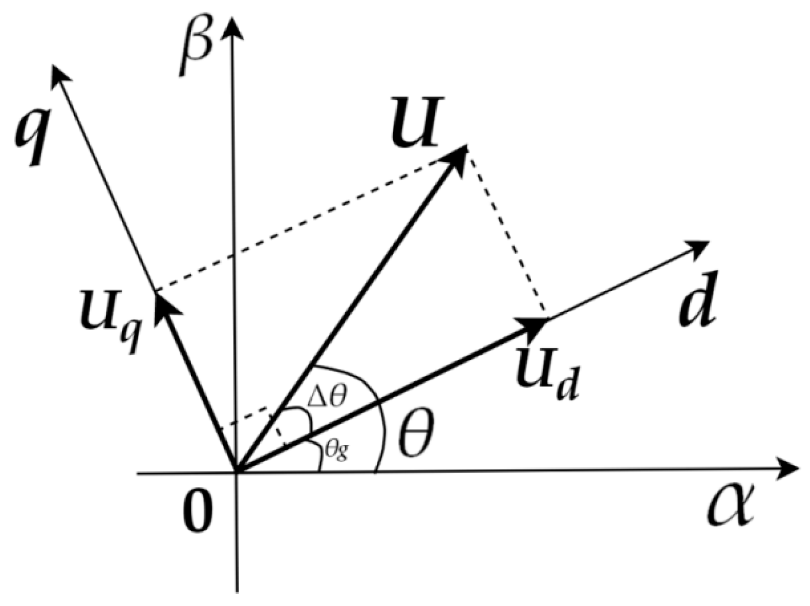
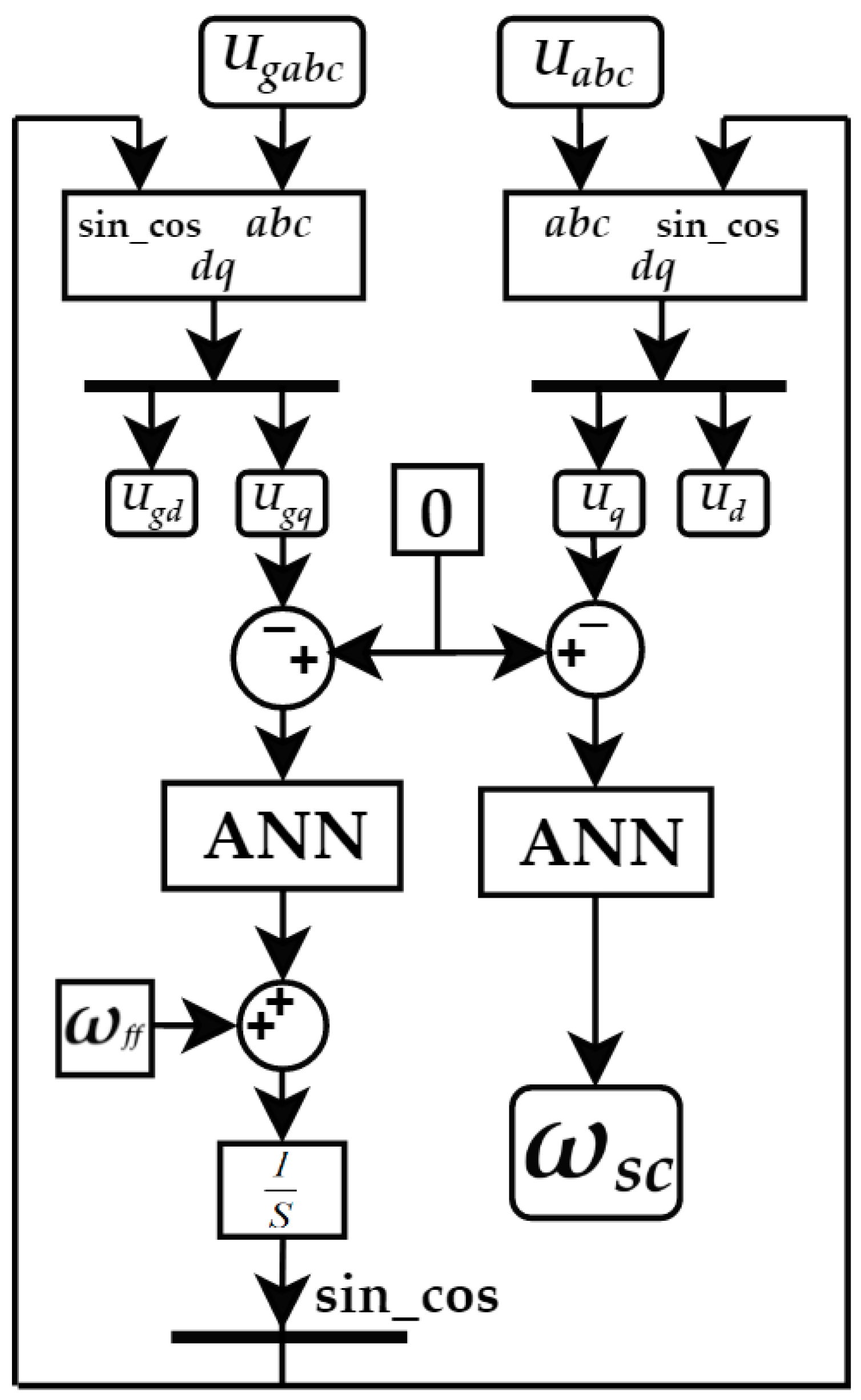
3.2.2. Pre-synchronization Control Algorithm of a Grid-Connected Operation

In order to satisfy the grid-connected conditions, under droop control, the amplitude and frequency of the inverter output voltage are consistent with the reference value. Only the phase factor can be considered at this time. In the dq rotating coordinate system, the phase θg and angular frequency ωg of the power grid voltage are obtained through the phase-locked structure. Then by adjusting the angular frequency of the output voltage of the microgrid inverter, the phase difference between the microgrid inverter and the power grid voltage tends to zero gradually. At the moment of Δθ = 0, the voltage of the microgrid and the power grid is completely synchronized. The schematic diagram of the process is shown in Figure 10.
The three-phase output voltage Uabc of the inverter was converted into Ud and Uq by Park transformation, as shown in (9) and θg is the phase angle of the power grid output voltage.
[ U d U q ] = 2 3 [ cos θ g cos ( θ g 2 π 3 ) cos ( θ g + 2 π 3 ) sin θ g sin ( θ g 2 π 3 ) sin ( θ g + 2 π 3 ) ] [ U a U b U c ]
Based on the CMAC and PID composite adaptive control algorithm, the pre-synchronization control algorithm proposed in this paper is shown in Figure 11.
The three-phase output voltage Ugabc of the power grid was transformed into Ugd and Ugq by Park transformation. Comparing the q-axis component Ugq with zero, the Ugq gradually tends to zero after being adjusted by the CMAC and PID composite adaptive control algorithm. When Ugq = 0, ωg is the angular frequency of the power grid voltage, the phase angle of the power grid voltage is obtained through an integral link. Through this closed-loop regulation process, θg is the output voltage phase angle of the power grid stable operation. The rated angular frequency of the power grid voltage is ωff, which is 100 πrad/s. θg is added to Park transformation of the three-phase output voltage Uabc of the microgrid. Comparing the q-axis component Uq with zero, the Uq gradually tends to zero after being adjusted by the composite adaptive control algorithm. When Uq = 0, the output angular frequency ωsc is the phase-locked tracking compensation angular frequency. By adding ωsc to the droop control link, and superimposing it with the angular frequency ω0 calculated by the active droop equation, the reference angular frequency ω of the microgrid inverter output voltage can be obtained. The calculation formula of the reference angular frequency is as follows:
ω = ω 0 + ω s c
The reference angular frequency ω of the inverter is added to the voltage and current double loop control link. Finally, the phase, frequency and amplitude of the microgrid inverter output voltage were consistent with the power grid voltage and the conditions of grid-connected operation were achieved.

4. Simulation Analysis

4.1. Simulation Analysis of Island Operation of DC Microgrid

In this paper, setting the filter time constant τ = 0.02 s of the DOB low-pass filter, Lfn = 10 mH, Cfn = 0.25 mF and Rfn = 0. The reference value of the DC bus voltage was set to 200 V [37]. The simulation parameters of the photovoltaic cell were as follows: Reference temperature Tref = 25 °C, illumination intensity Sref = 1000 W/m2, ISC = 8.58 A, Im = 7.94 A, Um = 17.7 V, Uoc = 22 V, α = 0.0025 /°C, β = 0.5 /°C and γ = 0.00288 /°C. When the simulation time is 2 s, the systems load increased suddenly. The waveforms of the DC bus voltage and bus power are shown in Figure 12 and Figure 13, respectively.
From Figure 12 and Figure 13, it can be concluded that the DC bus voltage was stable at 200 V, and the bus power was stable at the reference value of 1500 W after 0.6 s fluctuation. At 2 s, the system load increased suddenly. Since the power provided by photovoltaic cells cannot meet the power demand of the system, the bus power decreased obviously and the DC bus voltage decreased synchronously. Under the adjustment of the proposed algorithm, the DC bus power and bus voltage rose synchronously. The system underwent 0.55 s of transient fluctuation, and the DC bus voltage and bus power rose to the reference values of 200 V and 1500 W synchronously, finally reaching a stable state at the same time. The above simulation process shows that, under the adjustment of the proposed algorithm, the overload of the system does not cause the collapse of the system and there was no bus voltage deviation after the adjustment. The DOB solved the problem of excessive voltage deviation in the regulation process, the overshoot of bus voltage and bus power was controlled within 10%, which proved the effectiveness of the proposed algorithm.

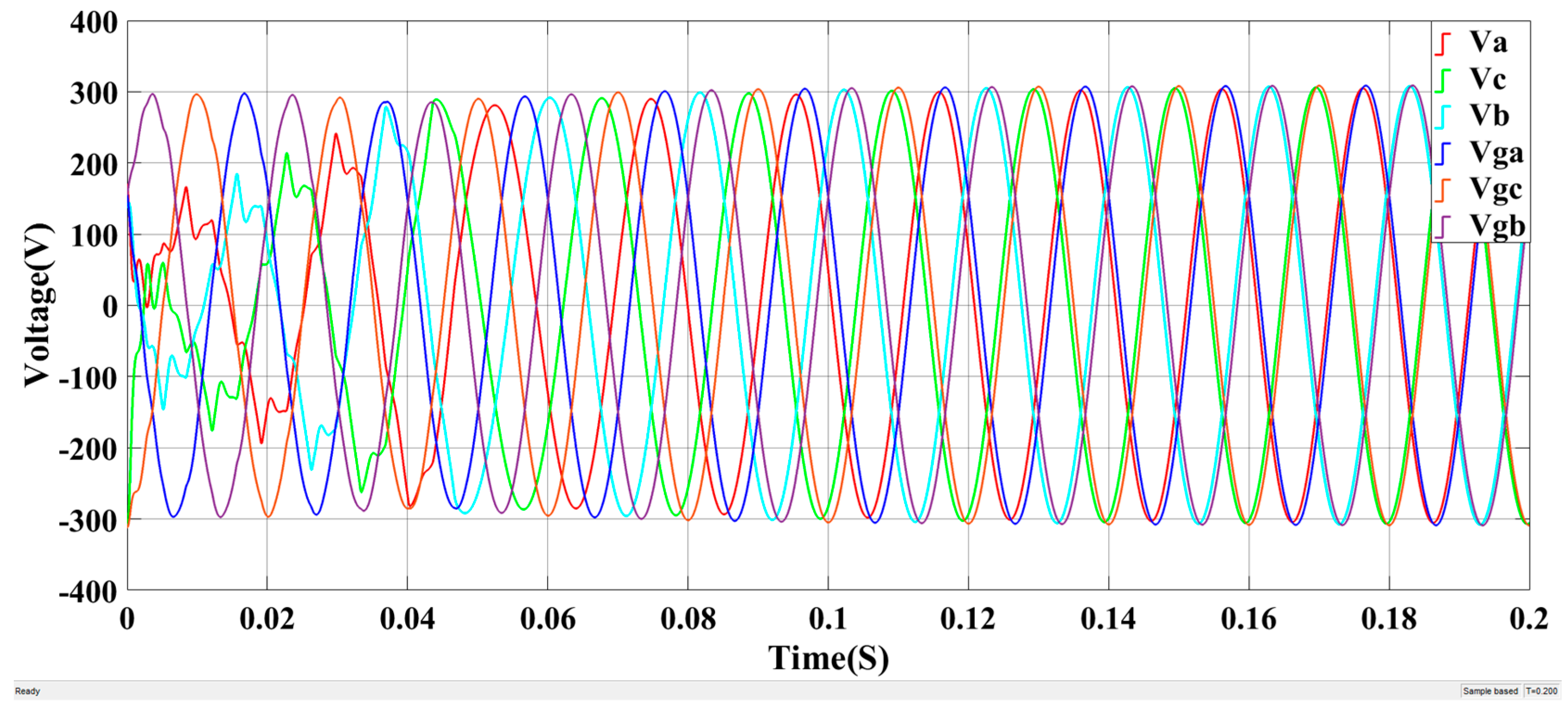
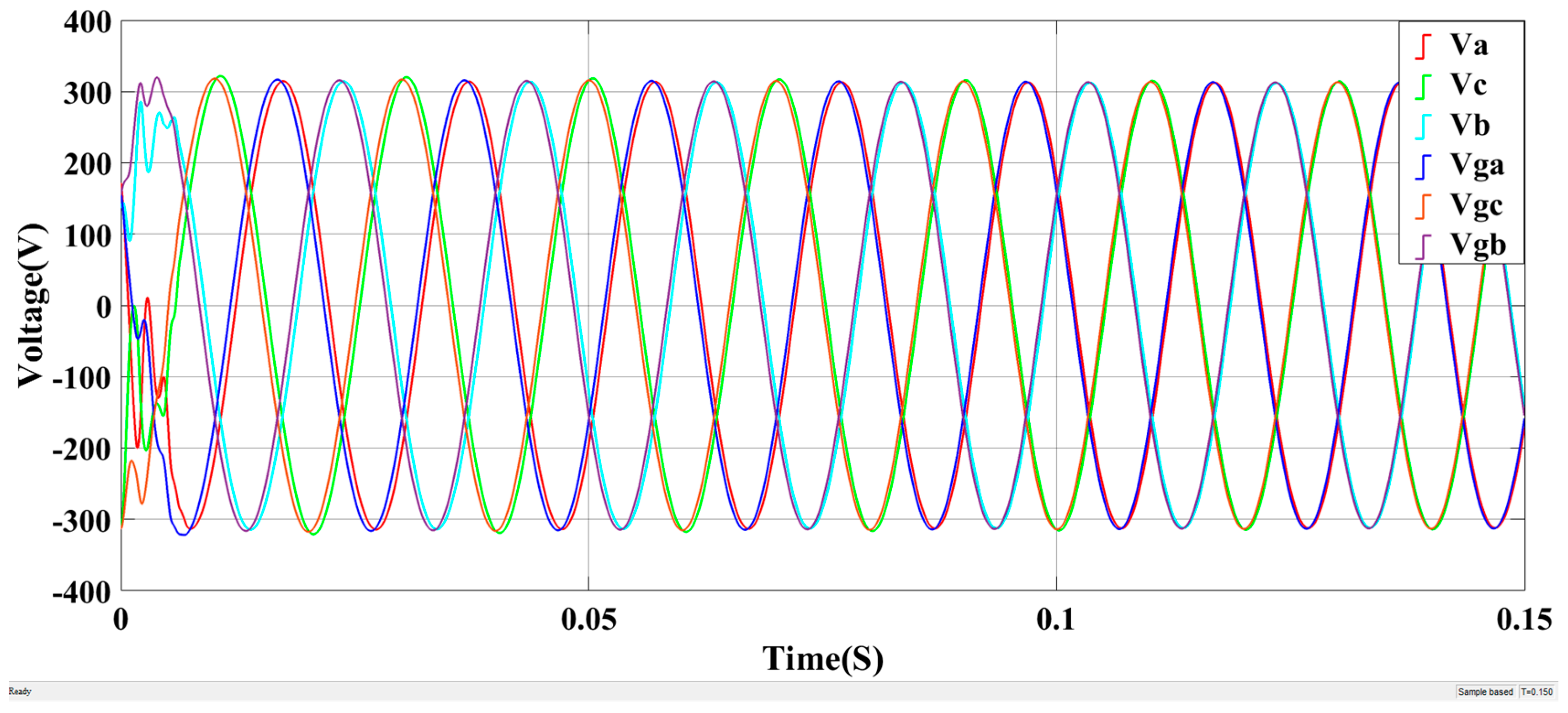
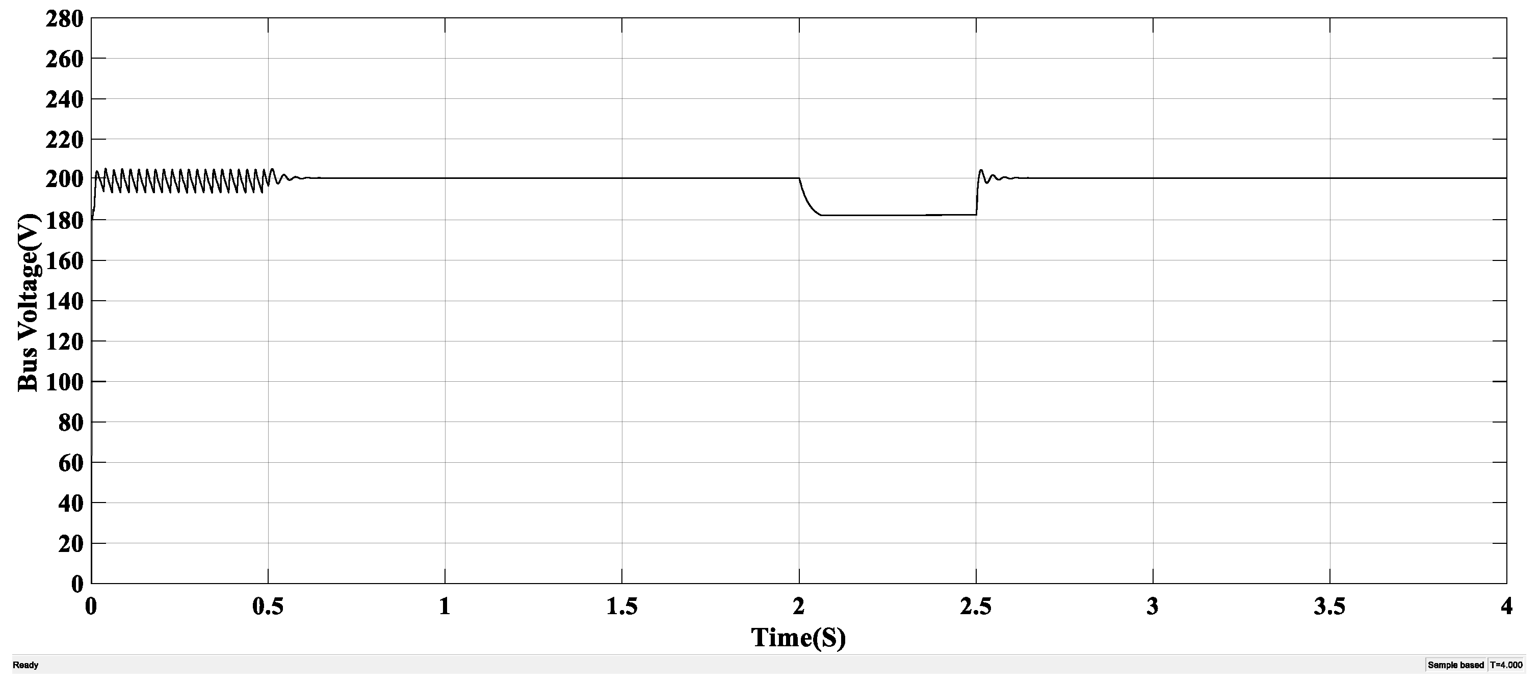
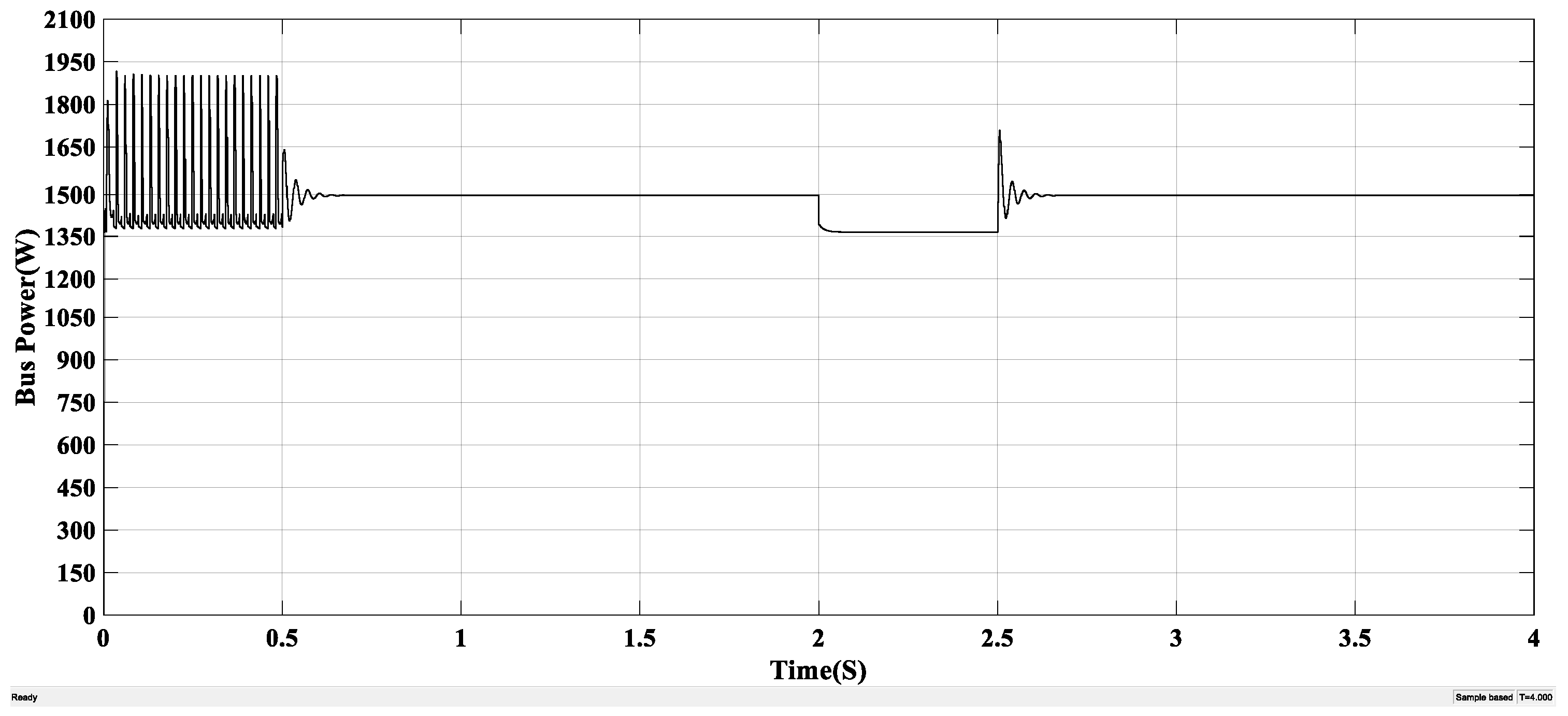
4.2. Simulation Analysis of Grid-Connected Operation of the DC Microgrid

For a grid-connected operation of the DC microgrid, the reference amplitude of the inverter output voltage was set to 311 V (effective value is 220 V). The LC filter parameters were set as follows: Lf = 0.6 mH and Cf = 1.5 mF. In order to verify the effectiveness of the improved droop control algorithm for the inverter, the inverter operated independently and the three-phase output voltage waveform of the inverter is shown in Figure 14.
The above simulation process shows that the voltage and current double loop control link eliminated voltage deviation, the output voltage was stable at the reference value and the adjustment time was only 0.01 s. After filtering via the LC filter, the output voltage followed a sinusoidal waveform with a waveform of high quality. The simulation results verified the effectiveness of the improved droop control algorithm for controlling the output voltage of the inverter.
In order to verify the effectiveness of the CMAC and traditional PID composite adaptive control algorithm, a square wave with an amplitude of 0.5 and f = 3 Hz was selected. The parameters of the neural network were set as follows: Network dimension N = 300, network normalized parameter c = 5, initial learning rate η = 0.10 and inertia coefficient α = 0.04. The parameters of the traditional PID were set as follows: kp = 0.01, ki = 0.1 and kd = 0.28. Under the action of this algorithm, the tracking experiment of the square wave was carried out. The simulation result is shown in Figure 15.
Since the learning rate was dynamically adjusted by the weight correction index up(k), it can be seen from Figure 15 that with the increase of learning times, up(k) decreased gradually, and the learning rate gradually decreased with the decrease of up(k). The convergence speed of the network changed from fast to slow, which ensured a smooth convergence process and avoided large oscillation. The output waveform of the neural network could completely track the square wave after about 0.04 s, with a short adjustment time, showing the system had a high stability.
In order to verify the effectiveness of the proposed pre-synchronization control algorithm based on the CMAC and PID composite adaptive control, the proposed algorithm was compared with the grid-connected control algorithm based on the PLL structure. The output voltage comparison diagram of the microgrid inverter and the power grid under the traditional PLL algorithm is shown in Figure 16. The output voltage comparison diagram under the proposed algorithm is shown in Figure 17.
From Figure 16 and Figure 17, it can be concluded that the inverter had obvious voltage oscillation under the traditional PLL algorithm, with a relatively long tracking time of 0.18 s. The proposed algorithm made the output voltage of the microgrid inverter track the power grid voltage in 0.05 s, with a required adjustment time of only 27.8% of the traditional PLL, and it achieved a complete synchronous and coordinated operation. There was no voltage oscillation and impulse current in the process, which guarantees the security of the system and verifies the timeliness of the proposed algorithm.

5. Discussion

A low-voltage DC microgrid with a DG has great potential in reducing power loss, enhancing power supply continuity and reliability as well as improving power quality. An adaptive approach for a distribution system reconfiguration and charging management of plug-in electric vehicles (PEV) is presented in [7]. It used a stochastic model predictive control to stochastically, adaptively and dynamically reconfigure the system, manage the incidental charging pattern of PEVs, and deal with the variable and uncertain power of renewable energy sources. The stochastic model predictive control (MPC) concept is applied in the problem to have dynamic and adaptability futures in the optimization problem and to deal with the uncertainty and variability issues of renewable energy resources in [8]. MPC is applied in the optimal reconfiguration of distribution systems, it has better consequences in the presence of variable power of renewables and increases the robustness and resiliency of optimization procedures of distribution systems. The intermittent modeling of renewable energy will be further studied in the next work.
At present, there is still much room for research on low-voltage DC microgrid. Further research is needed in aspects of system topology, electrical safety, reliability of power electronic equipment, control and protection methods as well as the treatment of DC corrosion problems. Various new energy generation technologies and their controls are still the future of microgrid development. These new energy generation technologies will provide more efficient and green energy for human beings and promote a sustainable development of the world.

6. Conclusions

In this paper, aimed at the low-voltage DC microgrid with photovoltaic and energy storage systems, a DC bus control algorithm based on the DOB was proposed for its island operation mode. The algorithm took the DC bus state and battery output state into account comprehensively. A DOB with second-order low-pass filter was designed to improve the anti-interference ability of the microgrid to system load change. The simulation results showed that when the system load suddenly increased, the DC bus voltage and power dropped. After the transient fluctuation of the system, the DC bus voltage and power synchronously rose to the reference value, and the system reached a new stable state. The proposed algorithm ensured that the system avoided a system collapse, that there was no voltage deviation, whilst ensuring that the bus power balance was realized at the same time. The introduction of the DOB resolved the problem of excessive bus voltage and power overshoot. This algorithm simplified the control system structure, reduced the cost and improved the autonomy, anti-interference ability and stability of the system. Therefore, the effectiveness of the algorithm was verified.
On the basis of the bus voltage stability of the DC microgrid, for the grid-connected operation of a microgrid, a pre-synchronization control algorithm was proposed based on the CMAC and traditional PID composite adaptive control algorithm. When the inverter ran independently, the improved droop control with virtual impedance eliminated voltage deviation and the adjustment time was very short. The LC filter improved waveform quality. Compared with the grid-connected control algorithm based on the traditional PLL structure, the proposed algorithm made the microgrid inverter output voltage track the power grid voltage quickly and accurately with an adjustment time of only 27.8% of the traditional PLL. The adjustment process did not produce voltage oscillation and impulse current, and the system had high stability.

7. Patents

The control algorithm proposed in this paper produces Chinese invention patents (No. 201811111204.7).

Author Contributions

Project administration, L.Z.; Validation, G.C.; Visualization, L.L.; Writing—original draft, K.C.; Writing–review & editing, L.Z.

Funding

This research was funded by the National Natural Science Foundation of China, grant number 51607031 and Science and Technology Research Project of the 13th five-year Plan of Jilin Provincial Education Department, grant number JJKH20180421KJ.

Conflicts of Interest

The authors declare no conflict of interest.

References

  1. Xiao, X.N.; Wang, P.; Chen, M. Secondary Voltage Control in an Islanded Microgrid Based on Distributed Multi-Agent System. Trans. China Electr. Soc. 2018, 33, 1894–1902. [Google Scholar]
  2. Yu, X.W.; She, X.; Ni, X.J.; Huang, A.Q. System Integration and Hierarchical Power Management Strategy for a Solid-state Transformer Interfaced Microgrid System. IEEE Trans. Power Electr. 2014, 29, 4414–4425. [Google Scholar] [CrossRef]
  3. Li, P.; Zheng, M.M.; Chen, A.W.; Han, J.P. Optimal Operation of Hybrid AC/DC Microgrid Based on Memetic Algorithm. Proc. CSEE 2018, 38, 3226–3234. [Google Scholar]
  4. Wang, L.; Lam, C.S.; Wong, M.C. Multifunctional Hybrid Structure of SVC and Capacitive Grid-Connected Inverter (SVC//CGCI) for Active Power Injection and Nonactive Power Compensation. IEEE Trans. Ind. Electr. 2019, 66, 1660–1670. [Google Scholar] [CrossRef]
  5. Yong, J.; Xu, X.; Zeng, L.Q.; Li, L.L. Research Overview of Low Voltage DC Power Supply System. Proc. CSEE 2013, 33, 42–52. [Google Scholar]
  6. Dragicevic, T.; Guerrero, J.M.; Vasquez, J.C.; Skrlec, D. Supervisory Control of an Adaptive-droop Regulated DC Microgrid with Battery Management Capability. IEEE Trans. Power Electr. 2014, 29, 695–706. [Google Scholar] [CrossRef]
  7. Rahmani-Andebili, M.; Fotuhi-Firuzabad, M. An Adaptive Approach for PEVs Charging Management and Reconfiguration of Electrical Distribution System Penetrated by Renewables. IEEE Trans. Ind. Inf. 2018, 14, 2001–2010. [Google Scholar] [CrossRef]
  8. Rahmani-Andebili, M. Dynamic and Adaptive Reconfiguration of Electrical Distribution System Including Renewables Applying Stochastic Model Predictive Control. IET Gen. Trans. Distrib. 2017, 11, 3912–3921. [Google Scholar] [CrossRef]
  9. Zhang, X.Y.; Shu, J.; Wu, C.H.; Zhou, L.H.; Song, X.R. Island Microgrid Based on Distributed Photovoltaic Generation. Power Syst. Prot. Control 2014, 42, 55–61. [Google Scholar]
  10. Papadaskalopoulos, D.; Pudjianto, D.; Strbac, G. Decentralized Coordination of Microgrids with Flexible Demand and Energy Storage. IEEE Trans. Sustain. Energy 2014, 5, 1406–1414. [Google Scholar] [CrossRef]
  11. Karimi, Y.; Oraee, H.; Golsorkhi, M.S.; Guerrero, J.M. Decentralized Method for Load Sharing and Power Management in a PV/Battery Hybrid Source Islanded Microgrid. IEEE Trans. Power Electr. 2017, 32, 6135–6144. [Google Scholar] [CrossRef]
  12. Gamboa, G.; Hamilton, C.; Kerley, R.; Elmes, S.; Arias, A.; Shen, J.; Batarseh, I. Control Strategy of a Multi-port Grid Connected Direct DC PV Charging Station for Plug-in Electric Vehicles. In Proceedings of the IEEE Energy Conversion Congress and Exposition, Atlanta, GA, USA, 12–16 September 2010. [Google Scholar]
  13. Benidris, M.; Elsaiah, S.; Sulaeman, S.; Mitra, J. Transient Stability of Distributed Generators in the Presence of Energy Storage Devices. In Proceedings of the 44th IEEE North American Power Symposium, Champaign, IL, USA, 9–11 September 2012. [Google Scholar]
  14. Rahmani-Andebili, M. Stochastic, Adaptive, and Dynamic Control of Energy Storage Systems Integrated with Renewable Energy Sources for Power Loss Minimization. Renew. Energy 2017, 113, 1462–1471. [Google Scholar] [CrossRef]
  15. Rahmani-Andebili, M. Cooperative Distributed Energy Scheduling in Microgrids. In Electric Distribution Network Management and Control; Springer: New York, NY, USA, 2018; pp. 235–254. [Google Scholar]
  16. Salamonsson, D.; Sannino, A. Low-voltage dc Distribution System for Commercial Power Systems with Sensitive Electronic Loads. IEEE Trans. Power Deliv. 2007, 22, 1620–1627. [Google Scholar] [CrossRef]
  17. Feng, W.; Sun, K.; Guan, Y.J.; Guerrero, J.M. Active Control Strategy Based on Hierarchical Control for Grid Connected Harmonic Current in Microgrid. Trans. China Electrotech. Soc. 2018, 33, 1400–1409. [Google Scholar]
  18. Jiang, Y.X.; Li, Y.G.; Tian, Y.J.; Wang, L. Phase-Locked Loop Research of Grid-Connected Inverter Based on Impedance Analysis. Energies 2018, 11, 3077. [Google Scholar] [CrossRef]
  19. Gao, C.W.; Liu, X.M.; Chen, H.; Li, H.Y. Modelling and Operation Characteristics of Photovoltaic-Grid Complementary System. Trans. China Electrotech. Soc. 2017, 32, 200–207. [Google Scholar]
  20. Ghoddami, H.; Yazdani, A. A Mitigation Strategy for Temporary Over-voltages Caused by Grid-Connected Photovoltaic Systems. IEEE Trans. Energy Conver. 2015, 30, 413–420. [Google Scholar] [CrossRef]
  21. Yang, Y.H.; Zhou, K.L. Photovoltaic Cell Modeling and MPPT Control Strategies. Trans. China Electrotech. Soc. 2011, 26, 229–234. [Google Scholar]
  22. Fan, Z.F.; Bi, D.Q.; Ren, X.W.; Xue, T.L.; Chen, Y.G. Low Voltage Ride-through Control of the Photovoltaic/Battery Microgrid System. Power Syst. Prot. Control 2015, 43, 6–12. [Google Scholar]
  23. Mendis, N.; Muttaqi, K.M.; Perera, S. Management of Battery-supercapacitor Hybrid Energy Storage and Synchronous Condenser for Isolated Operation of PMSG Based Variable-speed Wind Turbine Generating Systems. IEEE Trans. Smart Grid 2014, 5, 944–953. [Google Scholar] [CrossRef]
  24. Lu, X.N.; Sun, K.; Guerrero, J.M.; Vasquez, J.C.; Huang, L.P. State-of-charge Balance Using Adaptive Droop Control for Distributed Energy Storage Systems in DC Microgrid Applications. IEEE Trans. Ind. Electr. 2014, 61, 2804–2815. [Google Scholar] [CrossRef]
  25. Liu, X.D.; Li, K. A novel sliding mode single-loop speed control method based on disturbance observer for permanent magnet synchronous motor drives. Adv. Mech. Eng. 2018, 10, 1–10. [Google Scholar] [CrossRef]
  26. Liu, Y.L.; Wang, H.; Guo, L. Composite Robust H-infinity Control for Uncertain Stochastic Nonllinear Systems with State Delay via a Disturbance Observer. IEEE Trans. Autom. Control 2018, 63, 4345–4352. [Google Scholar] [CrossRef]
  27. Anand, S.; Fernandes, B.G.; Guerrero, J.M. Distributed Control to Ensure Proportional Load Sharing and Improve Voltage Regulation in Low Voltage DC Microgrids. IEEE Trans. Power Electr. 2013, 28, 1900–1903. [Google Scholar] [CrossRef]
  28. Hamzeh, M.; Karimi, H.; Mokhtari, H. Harmonic and Negative-sequence Current Control in an Islanded Multi-bus MV Microgrid. IEEE Trans. Smart Grid 2014, 5, 167–176. [Google Scholar] [CrossRef]
  29. Zhu, S.S.; Wang, F.; Guo, H.; Wang, Q.F.; Gao, Y.X. Overview of Droop Control in DC Microgrid. Proc. CSEE 2018, 38, 72–84. [Google Scholar]
  30. Li, P.; Zhang, X.S.; Zhao, B.; Wang, Z.L.; Sun, J.L. Microgrid Design and Mode Switching Control Strategy for Multi Microgrid and Multiple Dot Networks. Autom. Electr. Power Syst. 2015, 39, 172–178. [Google Scholar]
  31. Han, R.K.; Meng, L.X.; Guerrero, J.M.; Vasquez, J.C. Distributed Nonlinear Control with Event-triggered Communication to Achieve Current-sharing and Voltage Regulation in DC Microgrids. IEEE Trans. Power Electr. 2017, 33, 6416–6433. [Google Scholar] [CrossRef]
  32. Liu, S.C.; Wang, X.Y.; Liu, P.X. Impact of Communication Delays on Secondary Frequency Control in an Islanded Microgrid. IEEE Trans. Ind. Electr. 2014, 62, 2021–2031. [Google Scholar] [CrossRef]
  33. Wu, T.F. Tracking Control of Wheeled Mobile Robots Using Fuzzy CMAC Neural Networks. J. Internet Technol. 2018, 19, 1853–1869. [Google Scholar]
  34. He, S.D.; Dai, S.L.; Luo, F. Aaymptotic Trajectory Tracking Control with Guaranteed Transient Behavior for MSV with Uncertain Dynamics and External Disturbances. IEEE Trans. Ind. Electr. 2019, 66, 3712–3720. [Google Scholar] [CrossRef]
  35. Chao, F.; Zhou, D.J.; Lin, C.M.; Zhou, C.L.; Shi, M.H.; Lin, D.Z. Fuzzy Cerebellar Model Articulation Controller Network Optimization Via Self-adaptive Global Best Harmony Search Algorithm. Soft Comput. 2018, 22, 3141–3153. [Google Scholar] [CrossRef]
  36. Macnab, C.J.B. Comments on An intelligent CMAC-PD torque controller with anti-over-learning scheme for electric load simulator. Trans. Instit. Meas. Control 2018, 40, 1741–1745. [Google Scholar] [CrossRef]
  37. Lakshmi, M.; Hemamalini, S. Nonisolated High Gain DC-DC Converter for DC Microgrids. IEEE Trans. Ind. Electr. 2018, 65, 1205–1212. [Google Scholar] [CrossRef]
Figure 1. Equivalent circuit of a photovoltaic cell.
Energies 12 01162 g001
Figure 2. A simulation model of a photovoltaic cell. CCS: controlled current source; IGBT: Insulated Gate Bipolar Transistor; MPPT: Maximum Power Point Tracking.
Energies 12 01162 g002
Figure 3. A control flow chart of the disturbance observation method.
Energies 12 01162 g003
Figure 4. A control flow chart of the DC bus control algorithm. PI: proportion-integral; DOB: disturbance observer.
Energies 12 01162 g004
Figure 5. A DOB control structure.
Energies 12 01162 g005
Figure 6. A structure diagram of the voltage source inverter control system. PWM: Pulse Width Modulation; PCC: Point of Common Coupling; LC: inductance-capacitance.
Energies 12 01162 g006
Figure 7. Voltage and current double loop control link with virtual impedance.
Energies 12 01162 g007
Figure 8. A cerebellar model articulation controller (CMAC) control structure diagram. VAS: virtual associative space; PSS: physical storage space.
Energies 12 01162 g008
Figure 9. A CMAC and PID composite control structure diagram.
Energies 12 01162 g009
Figure 10. A schematic diagram of pre-synchronization process.
Energies 12 01162 g010
Figure 11. The pre-synchronization control algorithm. ANN: artificial neural network.
Energies 12 01162 g011
Figure 12. The DC bus voltage waveform in island operation.
Energies 12 01162 g012
Figure 13. The DC bus power waveform in island operation.
Energies 12 01162 g013
Figure 14. A three-phase output voltage waveform of the inverter.
Energies 12 01162 g014
Figure 15. A square wave tracing experimental waveform.
Energies 12 01162 g015
Figure 16. An output voltage comparison diagram between the inverter and the power grid under the traditional PLL algorithm.
Energies 12 01162 g016
Figure 17. An output voltage comparison diagram between the inverter and the power grid under the proposed algorithm.
Energies 12 01162 g017

