1. Introduction
As the need for more convenient methods of charging electrical equipment has grown, wireless power transfer (WPT), a novel power supply mode, has received increasing attention. Unlike traditional power transmission, which is wire-based, WPT technology is not constrained by cables, does not produce electrical sparks, and has high mobility. Due to these advantages, it has become a hot research topic in the field of energy transfer [
1,
2,
3].
At present, WPT is generally used to supply power on a one-to-one basis. For example, wireless charging has been applied to electric vehicles [
4,
5,
6] and to supply power to embedded medical equipment [
7,
8,
9]. In addition to this, the wireless charging of intelligent electronic devices is also a popular application [
10,
11,
12], one which has developed into an industry in itself. Meanwhile, charging standards have already been formulated for wireless charging. With the development of smart technology, the multi-load power supply scenarios such as smart home wireless charging and mobile electric vehicle wireless charging will be applied. It is foreseeable that the application of WPT technology will become increasingly popular as the technology, and other new power technologies, continue their rapid development. Furthermore, the technology can be expected to be able to charge multiple items of electrical equipment simultaneously (just like wireless fidelity or Wi-Fi allows the wireless connection of multiple devices).
However, numerous technological difficulties still remain to be solved in the application of WPT to a system containing multiple loads (i.e., several items of electrical equipment). Firstly, in terms of the modelling of the system, an increase in the number of loads introduces more variables and higher-order nonlinearities [
13,
14,
15]. Secondly, different loads will have dissimilar power demands. (For example, mobile phones, desk lamps, and tablet computers using the same intelligent WPT surface will have very different power requirements. Therefore, it is difficult to guarantee the power demands of each of these different types of load.) Thirdly, the characteristics of WPT systems indicate that the spatial positions of the electrical devices also have a marked influence on the power they receive [
16]. Finally, for various reasons, new loads will frequently access the system (and existing loads will frequently leave) during the operation of the multi-load WPT system. This will clearly reduce the stability of the power load on the system and, thus, its efficiency. This research focuses on finding a method to maintain the stability of the power received by each load when the number of loads changes. We also propose a corresponding control method to optimize the efficiency of the system.
Numerous scholars have studied the problem of controlling load power and efficiency of multi-load WPT systems, and they have made some significant achievements. In Ref. [
16], for example, a multi-load system is considered in which all of the load coils are treated as relay coils based on series–series (S–S) compensation topology. Subsequently, the multiple loads are able to receive the same energy at different distances. Another system based on S–S compensation topology has been analyzed using coupled-mode theory [
17]. In this work, the tuneable allocation of power to a multi-load system could be realized by dynamically controlling impedance matching. In Ref. [
18], a multi-load system based on S–S compensation topology was taken as the research object and the overall efficiency of the system maximized by adjusting impedance matching in the network. Subsequently, the input voltage of the system was regulated so that all of the loads in the system were able to receive the power they required. In Ref. [
19], the available and the transduce gains are defined in the form of the two-port network, which is helpful for the study of system characteristics and optimization of efficiency and power.
A frequency-tracking method is proposed in Ref. [
20] which uses a multiple-transmitter system. While this can improve performance overall, it cannot control the power delivered to each individual receiver (and hence the efficiency associated with each load). In Ref. [
21], the stability of the power received by each load was guaranteed as the number of loads in the system increased by constantly regulating the resonant capacitance in the system using a frequency-tracking method. A method of allocating the working frequency of a WPT system based on a single relay coil and self-resonant frequencies of each coil circuit therein has also been proposed [
22]. On this basis, a configuration method was proposed that ensured each load received an equal amount of charging power. In Ref. [
23], the operation mechanical of secondary side LCC (inductor–capacitor–capacitor) circuit under a rectifier load and the transfer efficiency characteristic under the rectifier load is studied. However, LCC structure on the secondary side will increase the volume and weight of the load equipment, and a simpler structure on the secondary side is more appropriate. A new impedance matching and power division method utilizing impedance inverters at receiver sides is proposed in Ref. [
24]. However, the influence of the cross-coupling of the receiving coil is neglected in this paper, and the control method of system efficiency optimization is not proposed. Aiming at a multi-load wireless power transfer system, Ref. [
25] analyzed the efficiency optimization methods of SP-SP (series–parallel capacitors and series–parallel capacitors), SP-PS(series–parallel capacitors and parallel-series capacitors), PS-SP(parallel- series capacitors and series–parallel capacitors) and PS-PS(parallel-series capacitor and parallel-series capacitors) topologies. The results show that the four topologies can achieve better efficiency optimization. Ref. [
26] introduced the LCC compensation network to WPT system oriented for dynamic wireless electric vehicle (EV) charging application, parametric design for both the LCC network used in the secondary side and the LCC network used in the primary side is elaborated theoretically. Ref. [
27] proposed a circuit, several paralleled LCC reactive power compensation networks in the primary side were excited by a sole inverter and the power distribution was realized automatically. Ref. [
28] proposes a double-sided LCC compensation network and its tuning method for wireless power transfer. However, these references have not yet proposed a load power stability control method with load access or exit.
In summary, the existing studies concerned with the optimization of multi-load WPT systems are mainly based on S–S (series topology in primary side and series topology in secondary side) compensation topology. In these studies, the following methods are generally used to optimize control over load power and system efficiency:
- (1)
Regulating the input voltage of the system in real-time to guarantee the stability of the power supplied to the loads;
- (2)
Changing the equivalent impedance of each load to optimize the load power and efficiency of the system;
- (3)
Using dynamic frequency tracking to realize optimum control over the efficiency of the system.
Although these control methods can optimize control over the system, they are complex. In addition, they influence the power supplied to the loads accessing the system and the efficiency of the system. Thus, they fail to guarantee that loads with different power demands receive the power they need. The complexity of the control process can be greatly reduced if the power received by the loads is guaranteed to be stable by designing a reasonable topology for the multi-load WPT system. Then, the system’s efficiency can be optimized on this basis.
To achieve this, in
Section 2 we analyse the characteristics of common multi-load WPT systems based on S–S compensation and reveal the dependency of the power load and efficiency on the number of loads connected. To guarantee the stability of the power received by the loads, an improved multi-load WPT system based on LCC/S (Inductor-capacitor-capacitor in primary side and series topology in secondary side)topology is proposed in
Section 3, wherein we also compare two important situations (with and without cross-coupling between receiving coils). Moreover, suggestions are proposed to eliminate the effect of cross-coupling between receiving coils to improve the stability of the power received by the loads. In addition, this section also proposes a method to optimize control over system efficiency by studying the relationship between loads (impedances) of different value and the overall efficiency of the system. Finally, the effectiveness of the new system and proposed control method is verified experimentally in
Section 4.
2. Multiple-Load System Based on S-S Compensation
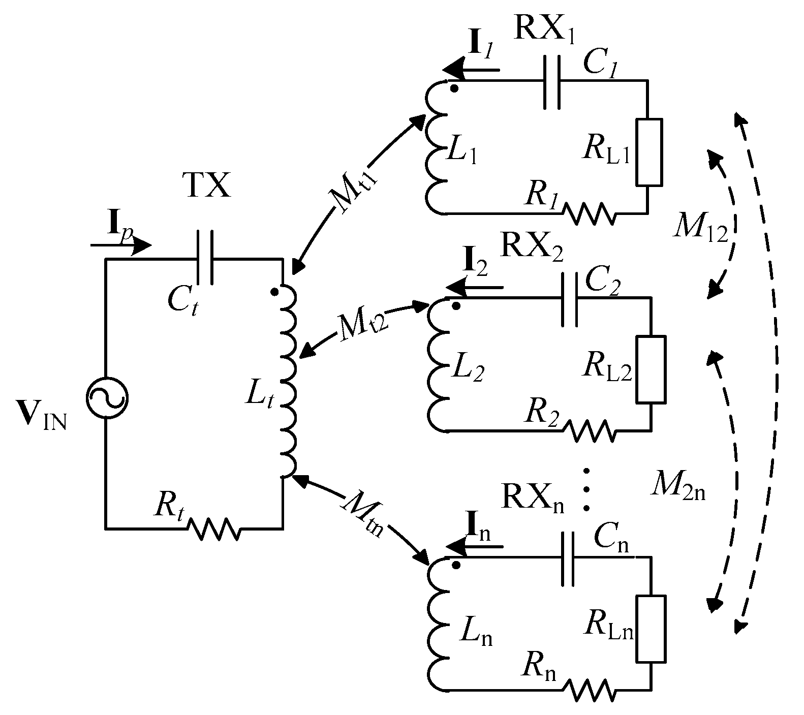
A circuit model for a multi-load WPT system that is commonly used is illustrated in
Figure 1. In the figure,
VIN is a high-frequency voltage source that supplies high-frequency alternating current (AC)
Ip to the system. The current produces a high-frequency electromagnetic field in the air as it flows through the transmitting coil on the transmission side and thus forms an induced voltage in the various receiving coils (so that the system simultaneously supplies power to multiple loads).
The inductances of the transmitting (TX) and
i-th receiving (RX
i) coils are
Lt and
Li, respectively. Furthermore,
Mti and
Mij represent the mutual inductances between TX and receiving coil RX
i and those between receiving coils RX
i and RX
j, respectively. Moreover,
Rt and
Ri are the internal resistances of these coils,
Ct and
Ci are their compensating capacitances, and the working frequency of the system is
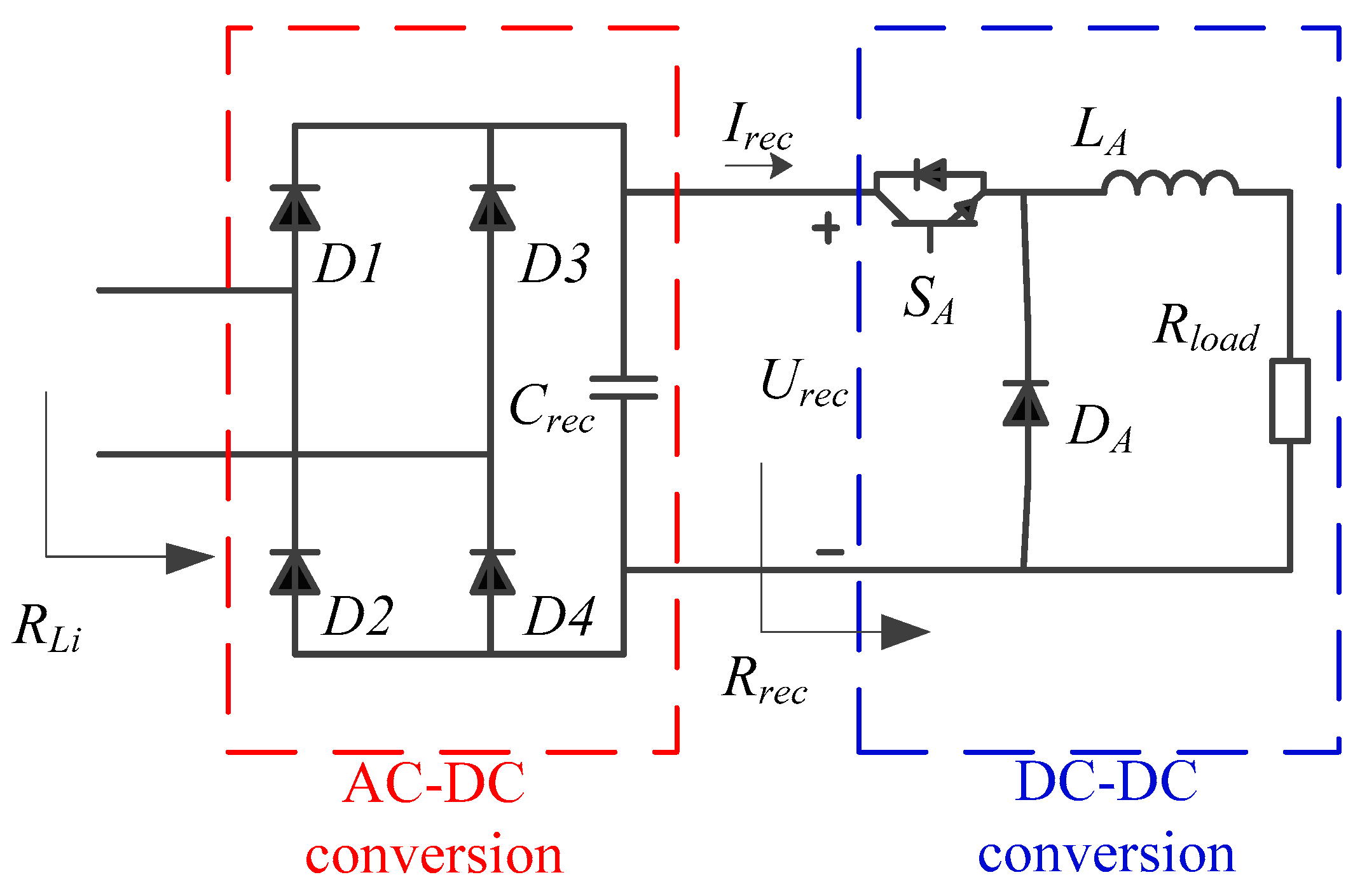
f. A WPT system generally uses a rectification and voltage regulation circuit (
Figure 2) to rectify the high-frequency AC before supplying power to the loads. As the rectified voltage
Urec and current
Irec are both direct, the direct current/direct current (DC/DC) conversion at the loads can be taken to be equivalent to a constant resistance,
Rrec, when the duty ratio
D of the driving signal of
SA remains unchanged.
As a result, the equivalent resistance of each load is
Therefore, each load can be represented by a constant equivalent resistance
RLi [
29].
Based on Kirchhoff’s voltage law, a matrix equation describing the relationship between the input voltage
VIN, current
Ip in the transmitting coil, and the currents
Ii in each receiving coil, can be written as follows:
where
Zt =
Rt + j
ωLt + 1/(j
ωCt),
Z2i = j
ωLi + 1/(j
ωCi) +
Ri +
RLi.
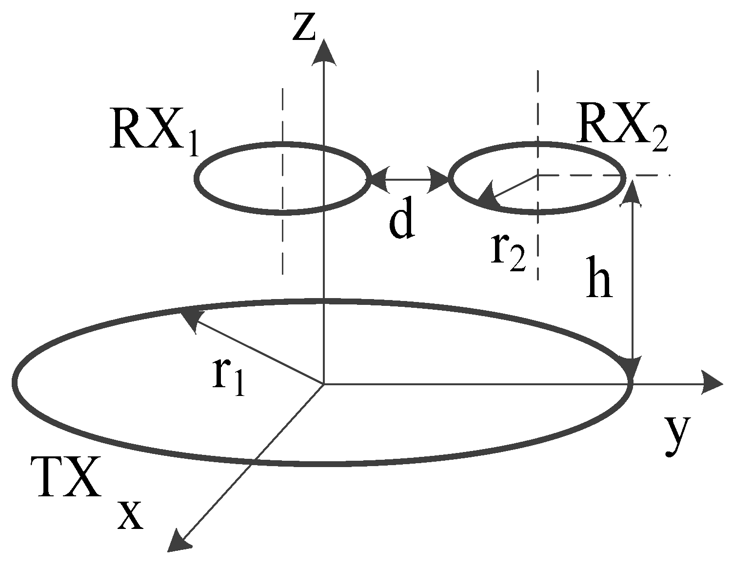
In a multi-load WPT system, TX generally has a larger size than the receiving coils to guarantee that the system has enough output capacity to enable it to simultaneously meet the power demands of each load. The position of the receiver coil is specified before the circuit design. For the sake of convenience, in this analysis we assume that all of the receiving coils are identical and in the same plane, i.e., we have a planar transmitting WPT system. The positions of coils TX and RX
i in normal operation are as shown in
Figure 3. In this diagram,
h represents the distance between the transmitting and receiving coils,
d refers to the distance between receiving coils, and
r1 and
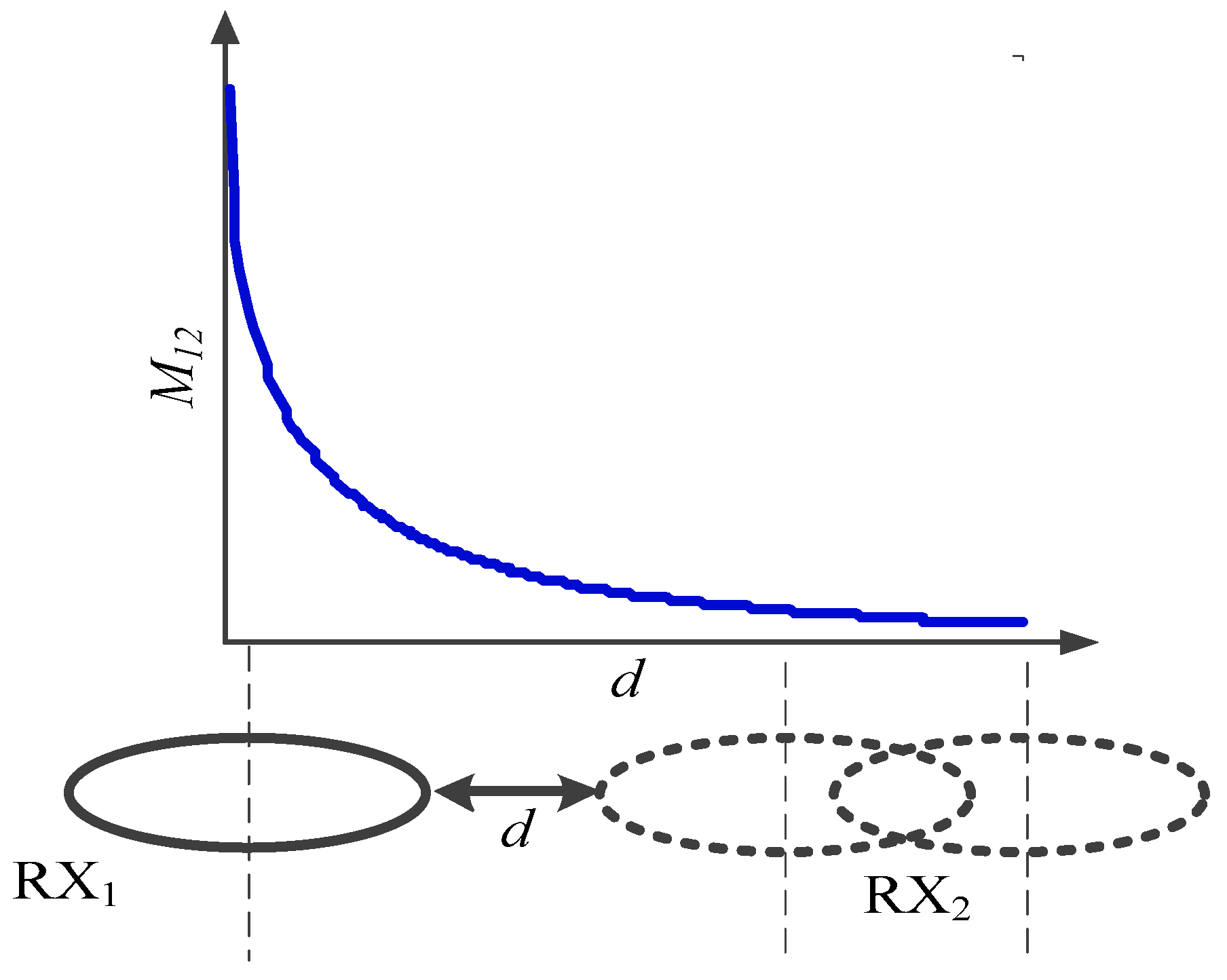
r2 denote the radii of the transmitting and receiving coils. Neumann’s equation indicates that the mutual inductance between the receiving coils is related to the distance
d. As shown in
Figure 4, cross-coupling between receiving coils can be ignored when the distance between the horizontal positions of the receiving coils reaches a certain distance as their separation is adjusted [
30].
Supposing that the distances between the horizontal positions of the receiving coils is sufficiently great (so that cross-coupling can be ignored), we have
Mij = 0 (i ≠ j; i, j = 1, 2, …,
n). Let the working angular frequency of the system be such that
, so that the reflected impedance of each load equivalent to the transmitting coil is:
By substituting this into Equation (3), we can obtain the output current of the system in the transmitting side.
According to the theory of mutual inductance, the current in each receiving coil after compensation is:
Thus, the power received by each load is:
The input power of the system is:
Since the loss of the system is composed of two parts, namely the power loss at the primary side and the power loss at the secondary side. In order to facilitate the calculation of the overall efficiency of the system, the efficiency of each load in the whole system is defined as:
where
ηTXi represents the efficiency with which the power input to the system is transferred to the reflected impedance when the load
RLi is reflected to the primary side of the system, so:
Similarly, when the input power of the system is transferred to the RX side,
ηRXi denotes the efficiency ratio associated with transferring power to the load
RLi, then:
In this way, the efficiency of each load in the whole system can be obtained.
The overall efficiency of the system is:
The theoretical analysis above indicates that when the number of loads in the system changes, the core factor influencing the received power and efficiency ratios of the loads in the system is the total reflected impedance
Zref for all the loads in the primary side of the system. The computation reveals that when there are n − k, n, or n + k loads in the system (and other parameters are unchanged), the ratio of the current flowing through the load
RLi to the power that the load receives is:
Likewise, when the number of the loads is n − k, n, or n + k, the efficiency ratio of the load
RLi in the whole system is:
It can be seen that when the number of loads changes in the system, the current flowing through load RLi changes consistently with the efficiency ratio of the load in the whole system.
The joining and leaving of loads connected to a multi-load WPT system is expected to occur frequently. It can be seen from Equations (7) and (12) that the power received and efficiency ratio of each load in the system are related to the overall condition of the loads in the system at any particular moment. For this reason, increasing or decreasing the number of loads is bound to change the overall efficiency of the system and the power transmission balance of each load. Considering this, an improved multi-load WPT system based on LCC/S topology is proposed to guarantee the stability of the power received by the loads.
3. Multi-Load Wireless Power Transfer (WPT) System Based on LCC Compensation Topology
We have seen above that when the number of loads in a multi-load WPT system based on S–S topology changes, the fundamental reason for the change in power received by each load is attributable to the variation in the total reflected impedance
Zref in the secondary side of the system equivalent to the primary side. As a result, the emission current changes in the primary side. If the emission current in the primary side could be fixed (using an appropriately designed topology), then, even if
Zref varied, the design would favour the stability of the power load.
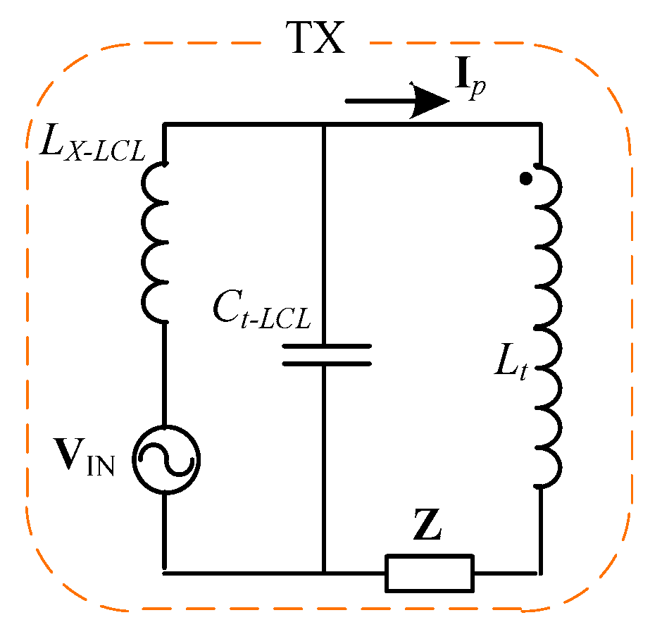
Figure 5 illustrates an LCL((inductor–capacitor–inductor)) structure in which
ωLt = 1/
ωCt-LCL =
ωLX-LCL (
Lt =
LX-LCL) and
Z represents an impedance of arbitrary magnitude that can be regarded as the total reflected impedance
Zref of the WPT system. The computation reveals that no matter how large
Z is, the current flowing through the inductor
LX-LCL is always
VIN/j
ωLp-LCL. If LCL topology is used for the primary topology of the WPT system, the power load can be guaranteed to be stable when the number of loads changes.
However, to simultaneously supply power to multiple loads in the system, the inductance of the transmitting coil essentially needs to be far larger than that of the receiving coils. Therefore, the coupling between the transmitting coil and the other receiving coils will be enhanced. While a constant current flow through the transmitting coil can be guaranteed using the LCL model, the input voltage of the system
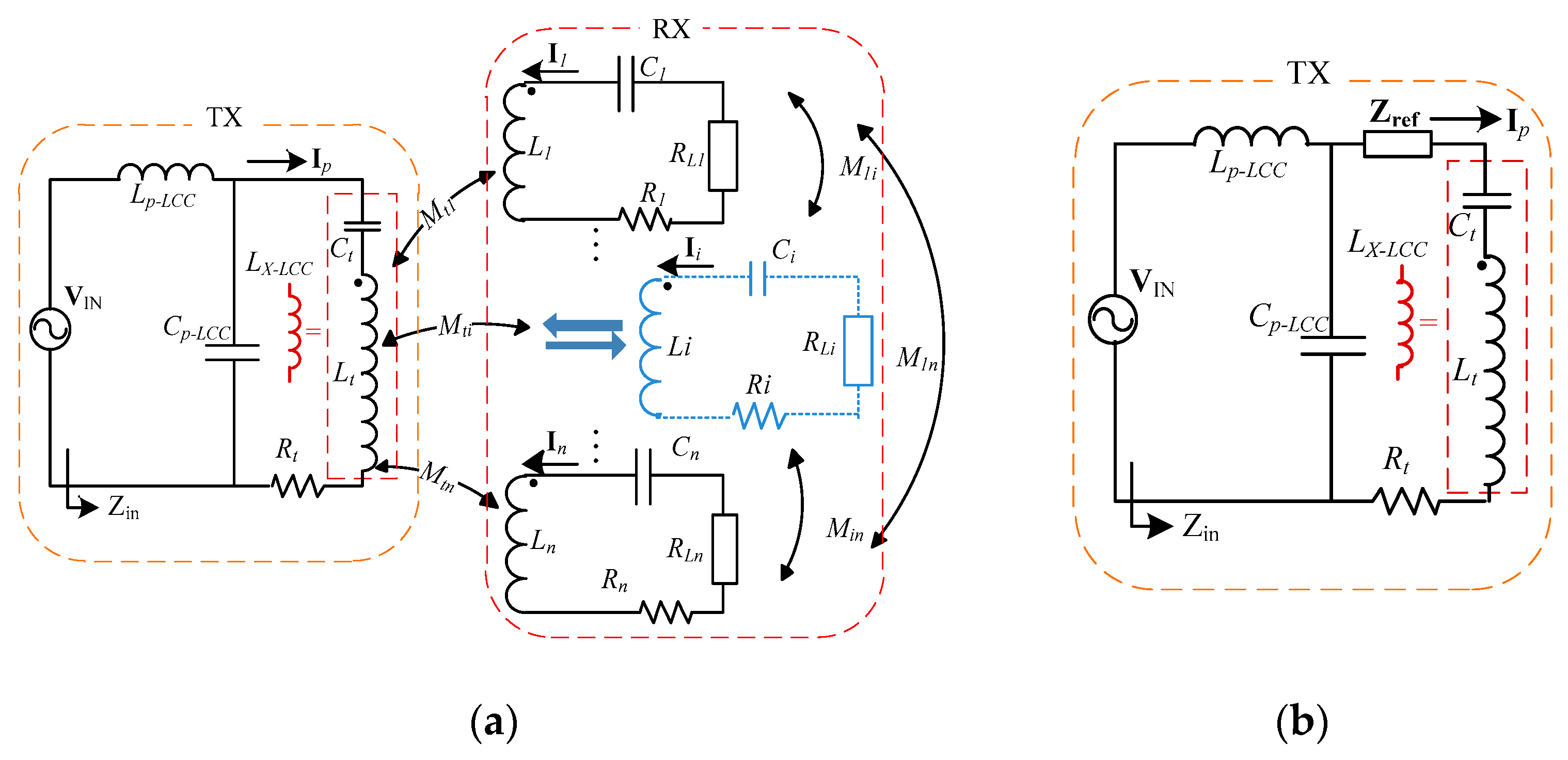
VIN is generally designed to be very large in order to meet the power demands of the loads. Therefore, we propose connecting a compensating capacitor
Ct in series at the transmitting coil
Lt so that an
Lp-LCC–
Cp-LCC–
Lx-LCC mode is formed in the transmission side of the system (
LX-LCC is used to describe the inductance of the transmitting coil in an LCC structure after the capacitor
Ct compensation), i.e., we have an LCC topology, as shown in
Figure 6.
Where
ωLp-LCC = 1/
ωCp-LCC =
ωLt − 1/
ωCt =
ωLX-LCC. Therefore, the input impedance
Zin can be obtained as:
Then, the formula of the input current can be obtained from the input impedance is:
Finally, the current
Ip flowing through the transmitting coil is:
It can be seen (compared with a multi-load WPT system based on S–S compensation) that the current flowing through the transmitting coil is independent of the circuit (number of loads) in the receiving side when the topology shown in
Figure 6 is adopted, i.e., the current is a constant [
27]. Meanwhile, this topology reduces the requirements placed on the supply voltage of the system (for a given demand in power load), simplifies the operating conditions of the system, and also lowers the cost of the system.
3.1. System Analysis Ignoring Cross-Coupling between Receiving Coils (‘Ideal’ Model)
The system shown in
Figure 6 comprises one transmitting and multiple receiving coils. As the compensating inductor
Lp in the transmitting side of the system is smaller than those in the receiving coils, its internal resistance can be ignored to make the analysis more convenient.
To ignore cross-coupling between receiving coils, we suppose that the receiving coils have large separations between them so that
Mij = 0 (
i ≠ j). Then, letting
ωLi = 1/
ωCi, the nodal voltage equation can be written according to
Figure 6.
The current flowing through each load can now be calculated using Equation (19).
Thus, the power received by each load is:
Equation (21) indicates that when cross-coupling is ignored between the receiving coils, the power received by load RLi is independent of the other loads. More precisely, it is merely related to parameters relevant to the transmitting side of the system and the mutual inductance between the transmitting and receiving coils. Therefore, the use of this LCC topology guarantees the stability of the power received by loads originally existing in the system when the number of loads is changed.
Similarly, the efficiency ratio of the power received by each load in the system can be obtained:
The overall efficiency of the system is:
3.2. System Analysis with Cross-Coupling between Receiving Coils (‘Real’ Model)
Of course, in practice the receiving coils are likely to be close to each other with their separation limited by the scope of the power supply. Thus, cross-coupling between receiving coils cannot be ignored. According to the circuit structure shown in
Figure 4, the nodal voltage equation can be rewritten as:
It can be seen from Equation (24) that the current flowing through the transmitting coil of the system always satisfies Equation (18), even if cross-coupling between receiving coils is considered, and remains unchanged due to the LCC compensation topology incorporated into the transmitting side.
Then, the current flowing through each receiving coil is:
Providing other parameters of the system remain the same, Equation (20) can be compared to Equation (25), whereupon we find that:
Based on Equations (25) and (26), the effects of considering cross-coupling between receiving coils on the transmission of power in the system are:
(1) Compared with the ideal model (ignoring cross-coupling between receiving coils), the power received by each load is smaller in the real model (where cross-coupling is considered) for a given set of system parameters and number of loads.
(2) Although the multi-load WPT system based on LCC/S topology is able to improve the stability of the power load, because of the cross-coupling between the receiving coils the power received by the loads is reduced slightly when the number of loads in the system is increased.
3.3. Optimizing Power Load and System Efficiency in the Case of Cross-Coupled Receiving Coils
In practice, the cross-coupling between the receiving coils cannot be ignored. Based on the foregoing analysis, the multi-load WPT system based on LCC/S topology is optimized according to the following two aspects:
(1) Compensating capacitors are connected in series on the receiving side to eliminate cross-coupling between the receiving coils, so as to improve the stability of the load power when the number of loads changes;
(2) The overall efficiency of the system is optimized by designing the load impedance appropriately.
As for the first optimization objective, the analysis above indicates that applying the LCC topology in the primary side of the system will reduce the tendency for the power received by the loads in the system to change due to loads accessing or leaving the system. However, due to the cross-coupling between receiving coils, a change in the number of loads will still affect the stability of the power received by the loads. To address this, we propose eliminating the influence of the cross-coupling between receiving coils by connecting compensating capacitors in series in the load circuits to further improve the stability of the power received by the loads.
To determine the capacitance, the matrix equations for the current and voltage of the system are rewritten according to the nodal voltage equation giving:
Because of the compensating capacitors, the currents in the sub-circuits of the loads in the presence of cross-coupling are the same as those in the ideal model (for the same system parameters and load number). Therefore, the value of the compensating capacitive reactance can be obtained by finding the difference between the above equation and Equation (19).
Given that
and
, the value of the compensating capacitive reactance is:
The above analysis reveals that provided the compensating capacitive reactance of the capacitors connected in series in the secondary circuits satisfies Equation (29), the cross-coupling between the receiving coils can be eliminated. In this way, the real system runs under the same conditions as the ideal system (where cross-coupling between receiving coils is ignored). In addition, the effect of loads accessing or leaving the system on the stability of the power received by the other loads is greatly reduced, thus realizing the first optimization objective.
At the same time, this also implies that the model for the real system can be converted to the model for an ideal system and then optimized. This dramatically simplifies the analysis process.
The second optimization objective can be tackled directly using the nodal voltage equation of the ideal system given in Equation (19). To optimize the overall efficiency of the system, we calculate the partial derivative with respect to
RLi of Equation (23), giving:
In accordance with the above equation, each load in the system needs to satisfy Equation (30) in order to ensure that the overall transmission efficiency of the system is optimized. Obviously, the optimal impedance of each load is irrelevant to the parameters of the other loads, being merely related to the number of loads and the coupling between the receiving coils of each load and the transmitting coil when the system has optimal transmission efficiency. This means that the efficiency of the system can be optimized by adjusting the duty ratio according to the impedance matching circuit shown in
Figure 2 (after obtaining the system parameters, number of loads, and mutual inductance between the load coils and transmitting coil). The mutual inductance is generally constant for a power supply in one plane.
4. Experimental Results
According to the foregoing analysis, a WPT system based on the LCC topology proposed in this research should be more suitable for supplying power to multiple loads at the same time than the commonly-employed multi-load WPT systems based on S–S compensation. To show that the above theoretical analysis is correct, a hardware system was therefore established for comparison and verification purposes.
Our first objective was to guarantee that each load can acquire the power it needs. To check that this objective can be achieved, multi-load WPT systems based on S–S and LCC/S topologies were established and compared. To facilitate the comparison and analysis process, the two systems were set up using transmitting coils of the same size, and the working frequency, receiving coils and loads were also the same. Meanwhile, the position of the receiving coils is specified before the circuit design. In the experiment, the mutual inductances between each receiving coil and the transmitting coil were configured to be identical by properly setting the locations of the receiving coils. Then the circuit is designed according to the position of transmitting coils and the load power demand. Cross-coupling was ignored in the initial design, and the final parameters used are detailed in
Table 1.
Based on
Table 1, we suppose that each of the systems has to supply power to two loads at the same time (both with 20 W power demands). Experiments were designed using three groups of parameters (
Table 2): Case 1 represents the parameters of the system based on S–S topology, and Case 2 and Case 3 relate to the system based on LCC topology. The difference between the latter two cases lies in their different compensating inductors
Lp.
According to the data in
Table 2, the system based on LCC/S topology reduces the demand on the supply voltage (compared to that based on S–S topology). This is achieved by appropriately designing the compensating capacitor/inductor (
Cp/
Lp) in the primary side for a given self-resonant frequency
f. For example, in cases 2 and 3, the designed values of
Lp and
Cp are such that the input voltage of the system required decreases from 11.2 to 8.9 V (but the power supplied to the loads remains the same).
Meanwhile, Equation (18) reveals that the current flowing through the transmitting coil of the system is controllable when the LCC topology is employed. Because of the influence of Lp, certain problems (such as the current exceeding the allowable limit in the transmitting side) did not occur due to the weak coupling between the transmitting and receiving coils. Therefore, the system using LCC topology in the primary side is a more suitable basis for a multi-load WPT system compared to one based on S–S topology, especially if the power in the system is high.
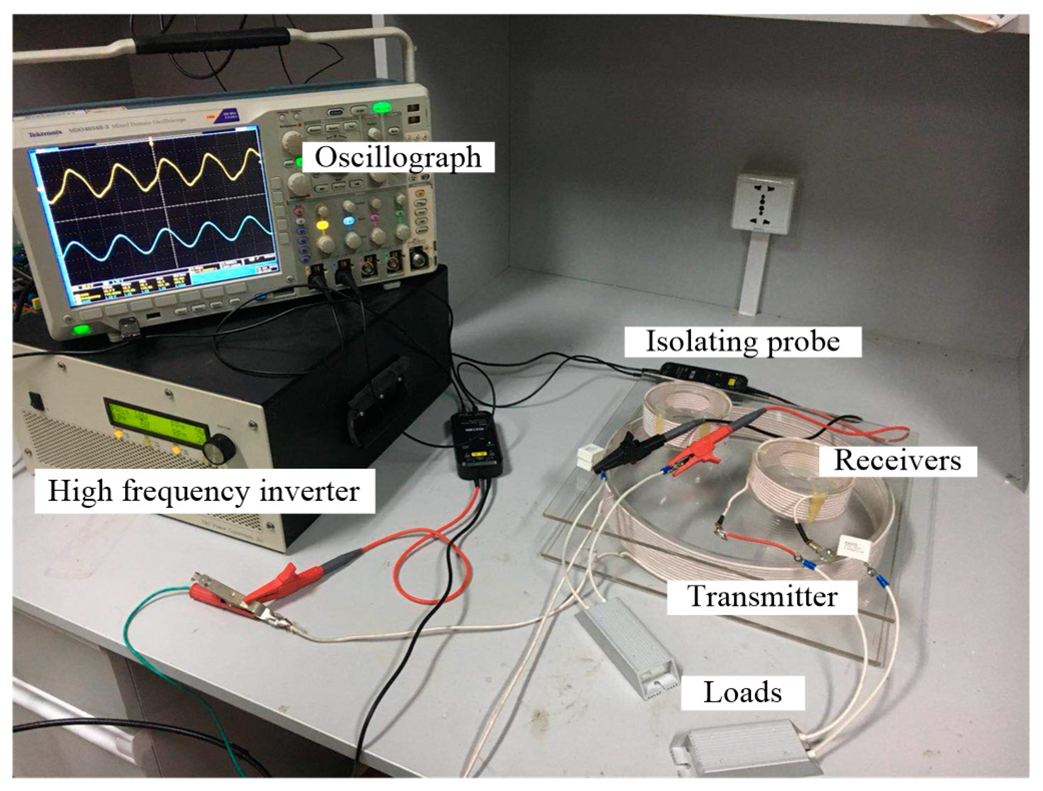
Figure 7 illustrates the experimental platform based on S–S topology that was built according to the system parameters given above. Both the transmitting and receiving coils were prepared by using litz wire of diameter 1.5 mm. The transmitting coil uses 13 turns and its internal resistance (i.e.,
Rt) is 186 mΩ. The number of turns and the internal resistance (
Ri) of the receiving coils were 12 and 40 mΩ, respectively. The transmitting and receiving coils were separated by a distance of 4 cm.
Based on the above system parameters, we suppose that the loads all have the same parameters. That is, the receiving coils and impedances of the loads have the same parameters.
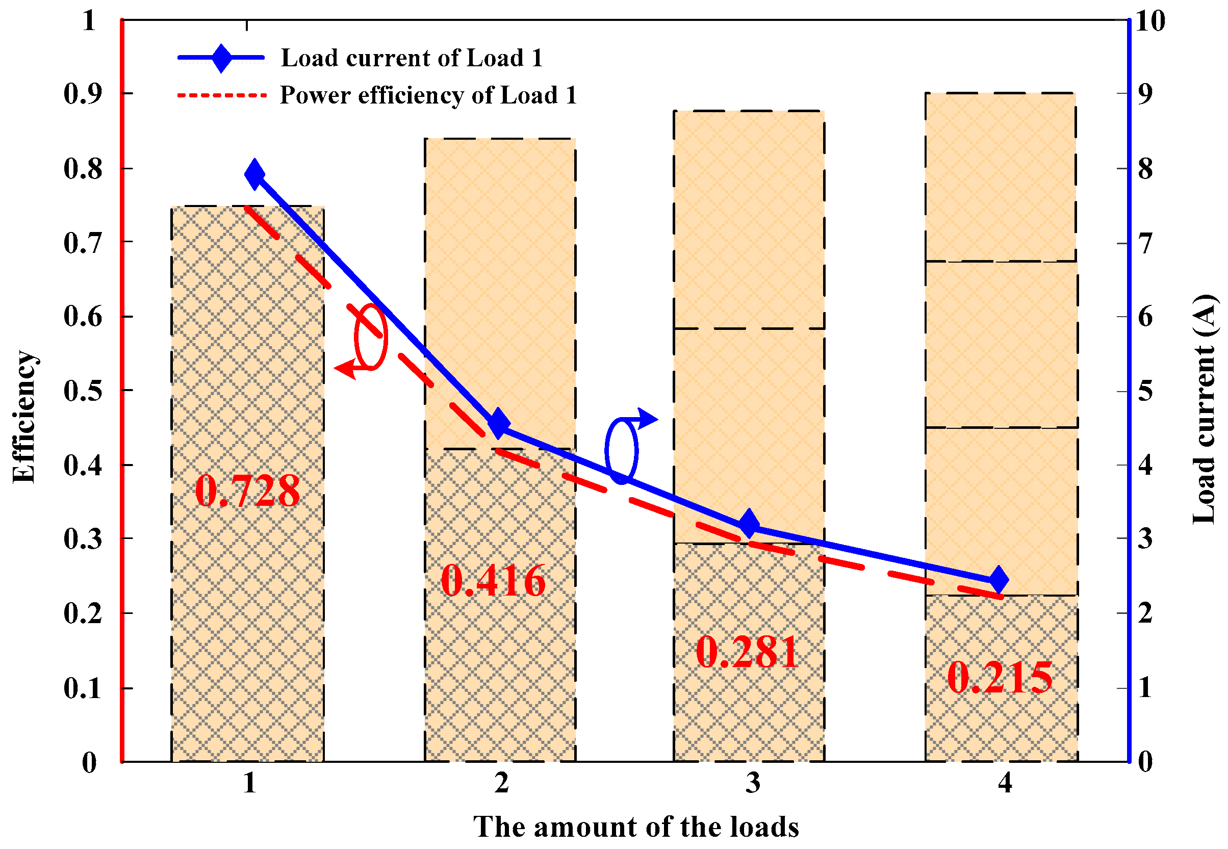
Figure 8 shows how the current flowing through the loads and the efficiency ratios of the loads in the system change as the number of loads changes. It can be seen from Equation (14) that the two factors vary according to the proportional relationship 1.1:0.62:0.43:0.33. In the figure, the actual change ratios for the load current are 7.9:4.32:2.98:2.24 and the actual efficiency ratios of the loads in the system are 0.73:0.42:0.28:0.22, respectively. The three sets of ratios essentially change in a consistent manner, which verifies that the theoretical analysis is correct. It also indicates that changing the number of loads greatly influences the power received by each load and the transmission efficiency of the system when the parameters are fixed and based on the S–S topology.
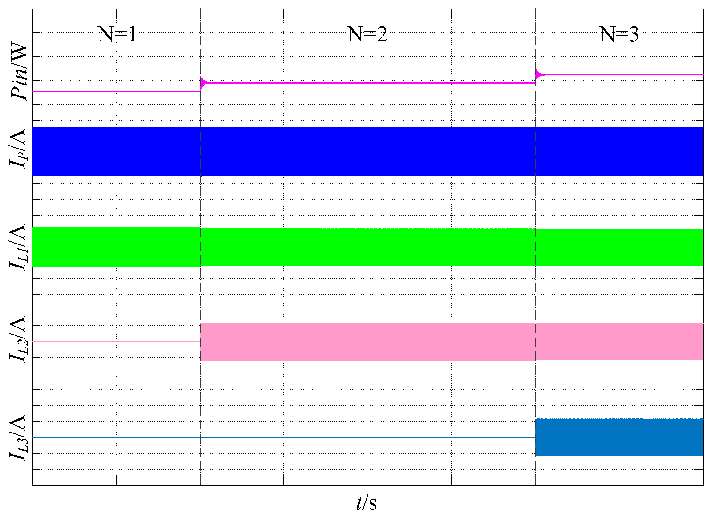
Next, a system based on LCC/S topology with parameters corresponding to Case 2 was tested. The waveforms shown in
Figure 9 are the input power
Pin, transmitting coil current
Ip, load 1 (the first load accessed to the system) current
IL1, load 2 (the second load accessed to the system) current
IL2 and load 3 (The last load accessed to the system) current
IL3 when the number of loads changes. As can be seen from
Figure 9, the transmitting coil current
Ip is basically unchanged when the number of loads changes from 1 to 3. And the current fluctuation of the load that has been accessed is also small after the new load is accessed.
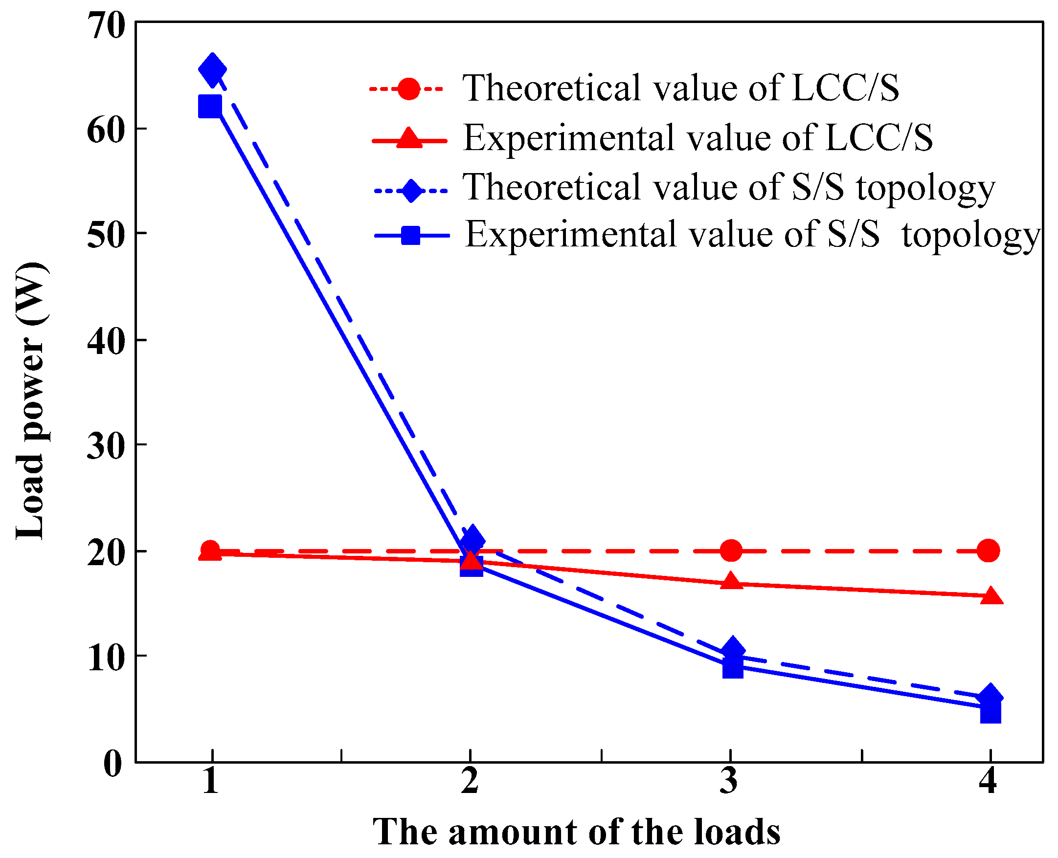
Figure 10 shows how the power received by the loads in this system changed when the number of loads was varied. In the multi-load WPT system based on S–S topology and only one load, the power received by the load reached 60 W when the initial excitation voltage was kept the same. This power level is far greater than the power level intended in the initial design of the system. In contrast, the power received by the load originally existing in the system based on LCC/S topology basically remains stable when the number of loads changes (at around 20 W, as designed). Therefore, introducing the LCC/S topology into the multi-load WPT system is capable of overcoming instability in the power received by loads due to the number of loads changing.
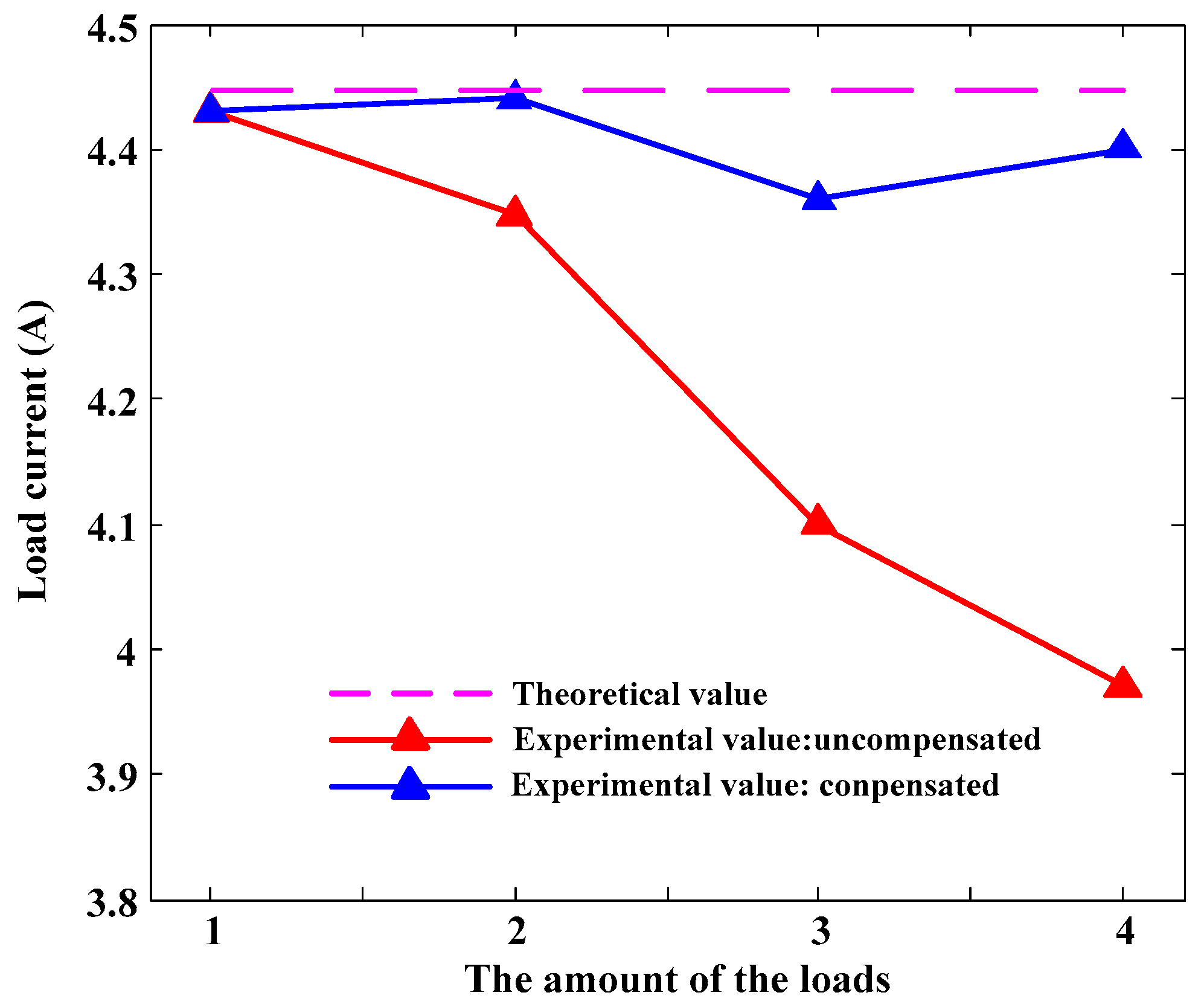
In these experiments, the value of the power received by the loads is designed to be 20 W, that is, the current flowing through the loads is designed to be 4.47 A. It can be seen from
Figure 10 that the actual power received declines as the number of loads increases. As already mentioned, this is mainly attributable to the effect of cross-coupling between receiving coils. It was found, via measurement, that the mutual inductance of the receiving coils was
Mij = 0.47 μH under the experimental conditions used. Thus, the capacitances of the compensating capacitors required to be connected in series in each load could easily be calculated. On this basis, the effect of cross-coupling between the receiving coils could be largely eliminated, thus stabilizing the power received by the loads to a value near to that designed theoretically.
Figure 11 illustrates the change in the load current with the number of loads when compensating capacitors were used to remove cross-coupling between receiving coils.
As shown in
Figure 11, the compensating capacitors essentially eliminate the effect of the cross-coupling between receiving coils as the number of loads changes. As a result, the load current basically remains around 4.4 A which is close to the designed value of 4.47 A. (When compensating capacitors are not used to counteract cross-coupling, the current decreased to 4 A when 4 loads were connected. Under these conditions, the power received by the loads is much lower than the power they require.)
Table 3 lists the values of compensating capacitance required, and the actual power received by each load, when there are different numbers of loads connected to the system. It should be noted that the compensation capacitance selected is the average value obtained within the range of mutual inductance changes between the receiver coils. The average capacitance value is selected through repeated experiments. Therefore, for the dynamic impedance changes, this paper adopts an approximate optimal compensation capacitance value. The experiments performed verify the feasibility of our proposed method of optimizing control over the power presented in
Section 3.3.
The theoretical analysis indicates that cross-coupling can be eliminated between the coils in the multi-load system based on LCC/S topology by using capacitance compensation. In this way, the real system operates in the same way as the ideal system (i.e., when there is no cross-coupling between receiving coils). Thus, the optimized control method obtained by analyzing the ideal system is also applicable to the real system.
We have suggested that the system should not only be optimized to ensure it satisfies the power requirements of the loads, but should also operate at optimal efficiency. As we have seen, the optimal efficiency of the system changes when the number of loads varies. To guarantee that the overall efficiency of the system is optimal, the resistance of each load needs to satisfy Equation (30). In accordance with the system parameters used in Case 2, we can thus derive the impedances of the loads required to realize the optimal efficiency of the system for different numbers of loads (
Table 4).
The experiment in our paper was designed under the existing conditions of the laboratory. Due to the low inductance of the receiving coil, the coupling between the receiving coil and the transmitting coil is not strong, so the theoretical values of the optimal impedances shown in
Table 4 are quite similar (around 1 ohm). Therefore, in the experiments, load resistances differing by 0.5 Ω were used in order to reveal the differences between the theoretically optimal impedances and actual optimal impedances required in the real system.
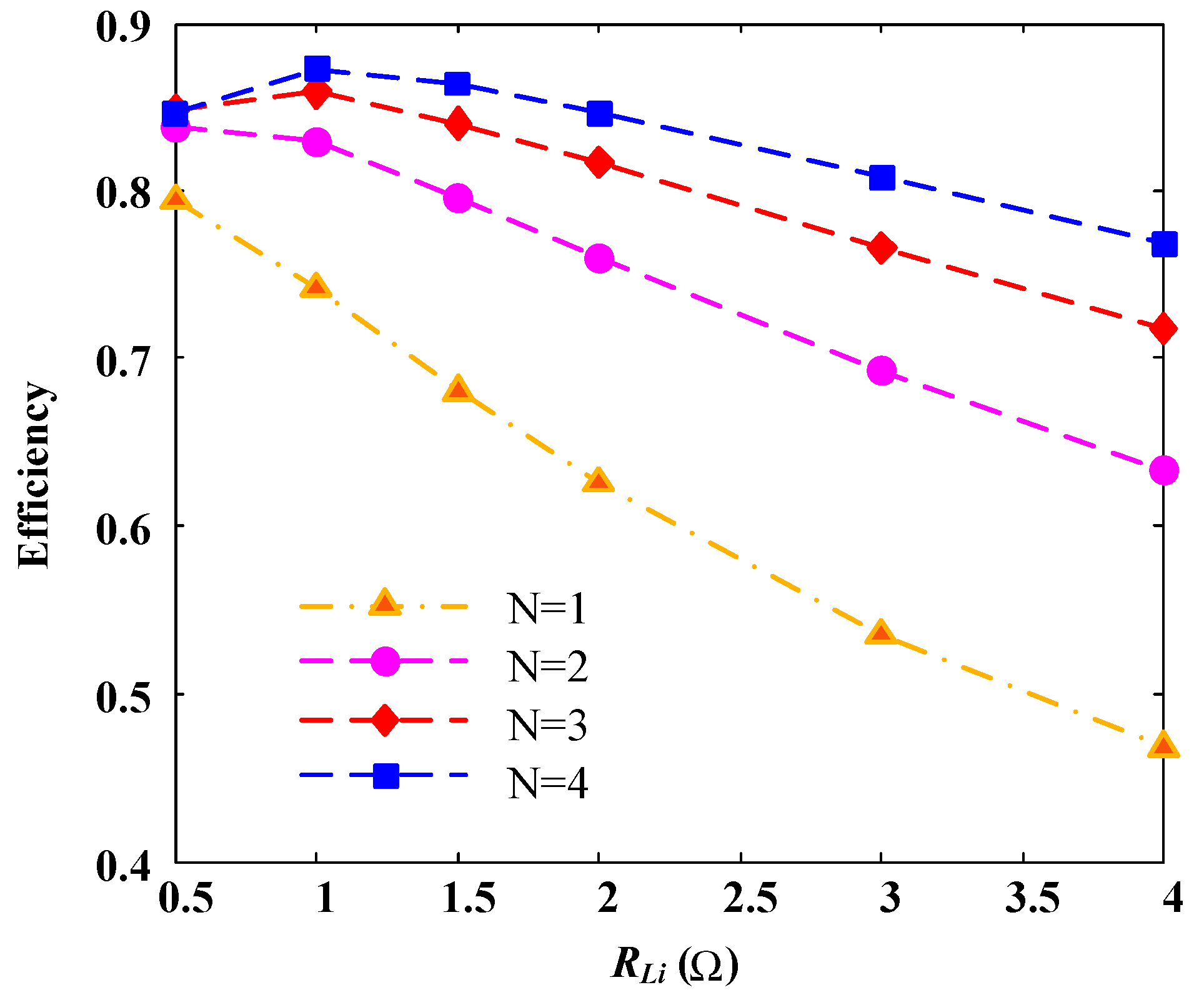
Figure 12 shows how the system efficiency changed with load resistance when different numbers of loads were used. For
N equal to 1–4, the theoretical and experimental values of the optimal impedance obtained are 0.39 and 0.5 Ω, 0.54 and 0.5 Ω, 0.67 and 1 Ω, and 0.77 and 1 Ω, respectively. It can be seen from the figure that the system efficiency can be optimized by changing the actual value of the impedance used. It also shows that the theoretically derived optimal impedances are close to the actual impedances required in the experiments.
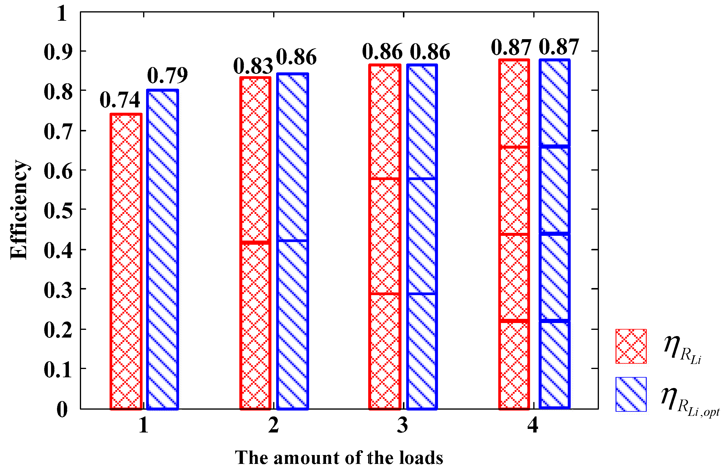
The experiments further indicate that the overall efficiency of the system can be optimized by adjusting the impedances of the loads accessing the system, as shown in
Figure 13. As can be seen from
Figure 12 and
Figure 13, the optimal load value shows an upward trend with the increase of the number of loads. And the overall efficiency of the system will gradually increase. Due to the limits of the selected load parameters in the experiments, although the loads in the actual simulations were different from the theoretical values when
N = 1 and
N = 2, which was helpful for improving system efficiency. It is conceivable that the efficiency of the system may be closer to the optimal theoretical value if a more precise method can be found to regulate the load impedance. When N = 3 and N = 4, the impedance before optimization was 1 Ω and that in the simulation was also 1 Ω after optimization. Hence, the system efficiency before and after optimization also remained unchanged. Therefore, as the number of loads in the system increases, the efficiency of the system can be optimized in any case by precisely regulating the equivalent impedance of the loads accessing the system.
As for the development of a control method which meets the power demands of loads in the system and makes the system run under optimal conditions in accordance with these power demands, further research is needed. We leave this problem to be further investigated in future work.


 ,
, 


