Review

System Configuration, Fault Detection, Location, Isolation and Restoration: A Review on LVDC Microgrid Protections

1
Department of Electrical and Electronic Engineering, Glasgow Caledonian University, Glasgow G4 0BA, UK
2
Department of Electrical Engineering, University of Engineering and Technology, Lahore (RCET Campus) 54890, Pakistan
3
State Key Laboratory of Alternate Electrical Power System with Renewable Energy Sources, North China Electricity Power University, Beijing 071003, China
*
Author to whom correspondence should be addressed.
Energies 2019, 12(6), 1001; https://doi.org/10.3390/en12061001
Submission received: 9 January 2019 / Revised: 5 March 2019 / Accepted: 10 March 2019 / Published: 14 March 2019

Abstract

:
Low voltage direct current (LVDC) distribution has gained the significant interest of research due to the advancements in power conversion technologies. However, the use of converters has given rise to several technical issues regarding their protections and controls of such devices under faulty conditions. Post-fault behaviour of converter-fed LVDC system involves both active converter control and passive circuit transient of similar time scale, which makes the protection for LVDC distribution significantly different and more challenging than low voltage AC. These protection and operational issues have handicapped the practical applications of DC distribution. This paper presents state-of-the-art protection schemes developed for DC Microgrids. With a close look at practical limitations such as the dependency on modelling accuracy, requirement on communications and so forth, a comprehensive evaluation is carried out on those system approaches in terms of system configurations, fault detection, location, isolation and restoration.

1. Introduction

Growing concern for climate change and carbon emissions (such as, EU’s plan for low-carbon economy by 2050 [1,2]) has directed the research focus towards the development and integration of Renewable Energy Sources (RES) to reduce fossil fuel usage and to enhance future energy sustainability. The EU’s framework plans to cut carbon emissions to 80–95% by 2050 and proposed to accomplish at least 27% renewable energy usage by 2030 [1]. However, the integration of renewable energy technologies into conventional power system is one of the main challenges to extract the maximum benefits from such technologies. This results in the evolution of the concept of smart grids to reduce operational cost, enhance efficiency and improve the resilience of power networks. With the development of smart grids, integration of distributed renewable resources at distribution level along with local loads and possible storages is forming a new structure characterized as Microgrids [2].
The incorporation of Distributed Energy Sources (DES) such as wind turbines, photovoltaic (PV) and energy storage systems on the end user side has demonstrated significant potential to reduce the use of fossil fuels and consequent CO2 emissions [3]. The interconnection of DES which behaves as a single entity as both a service provider to end customers and a customer to the utilities is termed as a microgrid [4]. Microgrids can be further categorized into AC and DC Microgrids. Extensive research and feasibility studies have been investigated for AC Microgrids because of its resemblance to the conventional macro AC power system. To avoid the unnecessary power conversion stages and simplify the complexity of system control, DC microgrid is proposed for a distribution system fully penetrated by power electronics converters. Exponential growth in the development of renewable energy resources (RES), energy storage systems (ESS) and electric vehicle infrastructure, led to the concept of distributing DC power at low voltage level, known as LVDC Microgrids [5]. The improved efficiency brought by the reductions of power conversion stages within a smart distribution system is the main contribution for the recognition of DC microgrid benefits.
Low and medium voltage DC are already in use in different applications such as railway traction systems, telecom data centres (up to 1.5kV) and vehicular power systems (up to 35 kV) [6,7]. The proliferation of RES with the increase in more RES, electronic loads and electric vehicles (EVs), demand in modern power systems has stimulated the concept of implementing LVDC distribution in residential and building applications as well. As a result, developing DC electrical system architectures, essential power electronics and protection devices have become the recent focus of research. Despite the fact of their extra benefits (such as reduced conversion stages, less losses, cost effectiveness, higher energy efficiency and so forth [8]), the development of an effective and economical protection scheme for a DC system with bidirectional power flow is still a bottleneck for DC Microgrids implementations. Consequently, widely acceptable guidelines and standards for LVDC microgrid protection is still to be explored [8]. For instance, some specified standards such as ETSI EN 300132-3-1, IEEE standard 946 and IEC SG4 have been developed for telecom data centres and DC auxiliary power systems in grids but they do not cover the protection aspect of LVDC microgrid system [9,10]. The lack of suitable standards is still one of the major limitations in the practical implementation of LVDC system of bidirectional power flow due to inadequate investigations.
Time constants for DC control and protections are usually very close, the post-fault behaviour of converters within a DC grid becomes a new issue that involves both active converter control and passive circuit transients. Therefore, a systematic view point has to be taken over the interaction among system configurations, protective device and strategies and individual power converters. And then, suitable schemes for the fault detection, isolation, location and restoration have to be developed with such interaction considered.
Existing reviews on the topic of LVDC Microgrids have mainly focused on the operation, control and energy management of the system [11]. The comprehension of integrating grid architecture, earthing configurations and circuit breaker selection simultaneously while developing the technique has not been adequately explored. Therefore, this paper presents protection systematic review considering system configurations, fault detections, locations, isolations and restorations.
The paper is organized as follows: Section 2 introduces the system configuration for LVDC Microgrids This section elaborates the DC Microgrid architecture, types of DC faults and earthing configurations for DC Microgrids. Circuit-breaking technology proposed for DC systems are all presented under Section 2. Evaluations and investigations of fault detection, isolation and fault locating methods are carried out in Section 3. Further, the post-fault restoration in DC Microgrids is analysed in Section 4. Finally, a conclusion is drawn in Section 5.

2. System Configuration

This section gives an overview and comparison on the configurations of LVDC distribution systems with respect to protection. LVDC networks are expected to play a promising role in the development of future power distribution networks. Different studies have been carried out for LVDC networks without developing any standard network and taking the impact of systems earthing for granted. However, since various grid configurations exists, an analysis of each configuration, earthing schemes, available circuit breaker technologies under different fault conditions is required to develop standard protection criteria for the network.

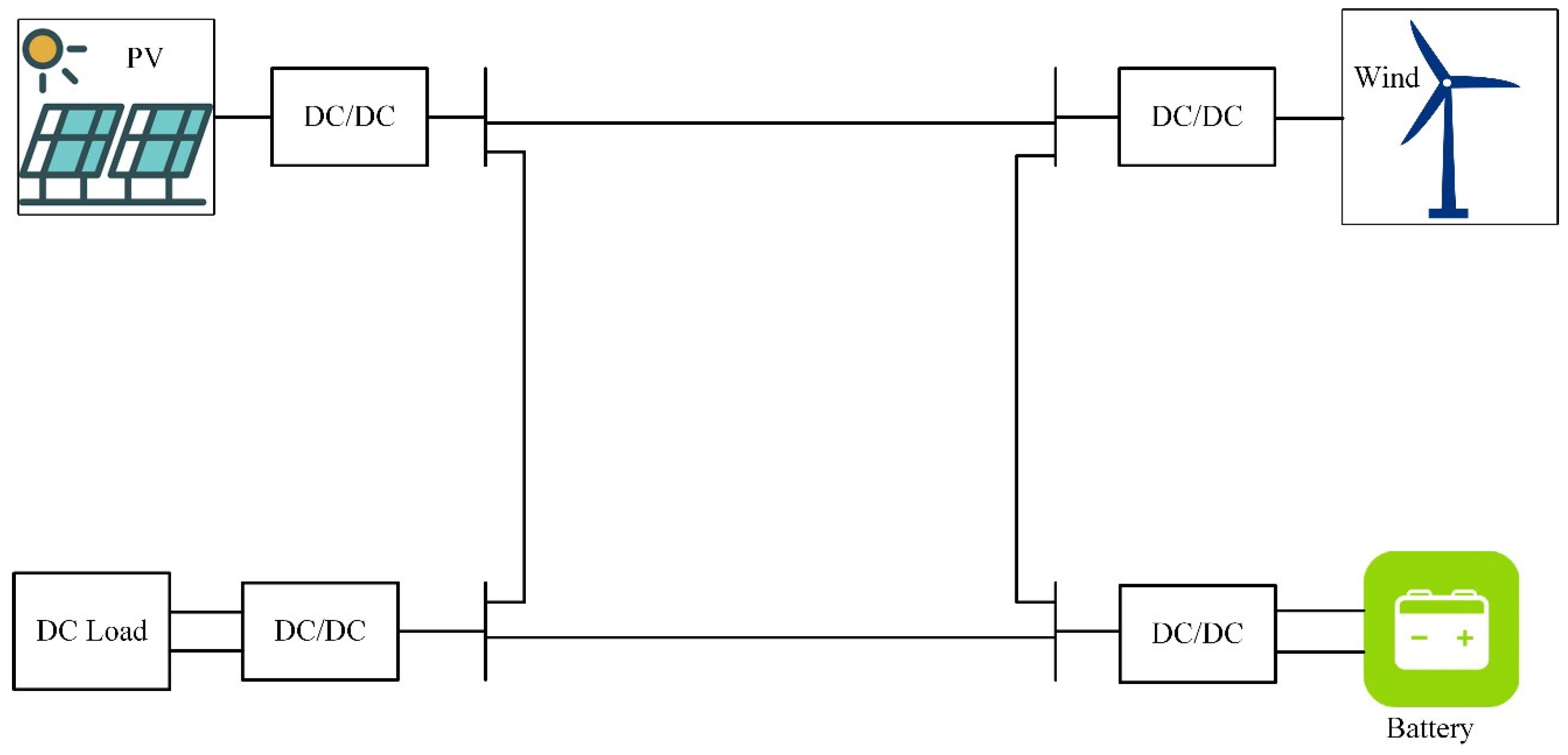
2.1. DC Microgrid Architecture

Similar as AC distribution network, there are a number of different DC Microgrid architectures considering specific design requirements and applications that have been proposed [11,12,13,14]. An analysis of DC configurations is carried out in this section, exploring the merits and demerits of the system. DC Microgrid architecture can broadly be classified as: (1) Single Bus Configuration, (2) Multi-bus Configuration, (3) Ring or Loop Configuration and (4) Interconnected Configuration.
Single bus topology interfaces AC generating renewable sources to DC bus via AC/DC converter. A single direction of power flow is created in the feeders towards the load. Figure 1 demonstrates the single line diagram for the single bus configuration in DC Microgrids [11,12].
Single bus topology is quite frequently in practice for supplying power in telecom applications at 48 VDC [14,15]. With simple structure and ease of voltage control, the available voltage level for a specific DC network is limited to one and a rigid pole-to-ground insulation requirement has to be considered according to the full pole-to-pole voltage when the negative pole is earthed.
By introducing bipolar configurations, the pole-to-neutral voltage becomes half of the pole-to-pole value [14] so the pole-to-ground voltage is reduced when neutral is earthed. DC bipolar regulated bus architecture, shown in Figure 2, with an operating voltage of +/−170 V was suggested [16]. In Figure 2, load side converters have the flexibility to be connected to voltages between 340, +170 and −170 V. The main challenge of such bipolar type system is the extra complexity of voltage regulation, voltage balancing between the poles in particular and the suppression of circulating current [14]. Such configurations are suggested to be implemented in residential buildings where multiple low voltage DC levels are required by appliances as well as a reduction of power converter stages and ratios [17].
The bipolar type configuration is further extended to a concept of multiple buses connections. This makes the system more flexible by providing different voltage levels between the buses (i.e., +170 V, −170 V and 340 V) which further improves power supply reliability [18]. The approach was further expanded to form a multiple DC Microgrid cluster configuration [19,20,21]. Whereas, developing a distributed control strategy among all the DC Microgrids and appropriate voltage regulation challenges are still under investigation for multi-bus architecture [22,23].
Simply enough to implement as a radial topology in a practical LVDC system, it might not be a suitable choice for a more complex distribution power system with multiple renewable sources, for example PV and Electric Vehicle (EV) charging systems. Its undesirable feature stems from the argument that radial structure may lower the reliability of the down-stream load feeders when a faulty bus occurs from the upper stream. On the other hand, if a permanent fault occurs at a lower-stream point, there is no other path to restore the power supply in a radial system so the downstream supply cannot be restored unless the fault it cleared.
Ring (or loop) type architecture in DC Microgrids has been proposed to provide sustainable power supply after the isolation of a permanent fault. Ring topology contains multiple paths among the sources and loads as shown in Figure 3. DC circuit breakers are suggested to be used to provide flexibility in disconnecting the faulty bus from the network. Intelligent Electronic Devices (IEDs) are suggested to control the line connection at each node and the links between neighbouring nodes [24]. Under faulty condition, IED detects the fault, isolates the specific faulty bus from the network and ideally enables supplies power using a healthy path. These type of topologies are proposed to be used in urban and industrial applications [22]. Similar to AC system, a ring network will allow the fault current to flow into the faulty point via multiple paths, which tends to increase the overall fault current and hence the complexity of protections as well.
Figure 4 demonstrates the interconnected configuration by connecting DC Microgrids to an existing AC network through AC-DC-AC converter interface, where, the power flow can be bidirectional according the requirements [22]. This configuration improves power supply reliability with the presence of a DC conversion stage in between AC systems, which can effectively regulate the fault propagation from one AC side to another. Interconnected configuration is often designed for the unmanned aerial vehicle (UAV), shipboards and aircrafts applications where power reliability is the primary concern [23].
As is shown above, since the system fault current contribution may vary according to the specific configuration of DC Microgrids, it adds up to the difficulty to develop a generic protection scheme that can effectively accommodate all kinds of DC microgrid configurations.

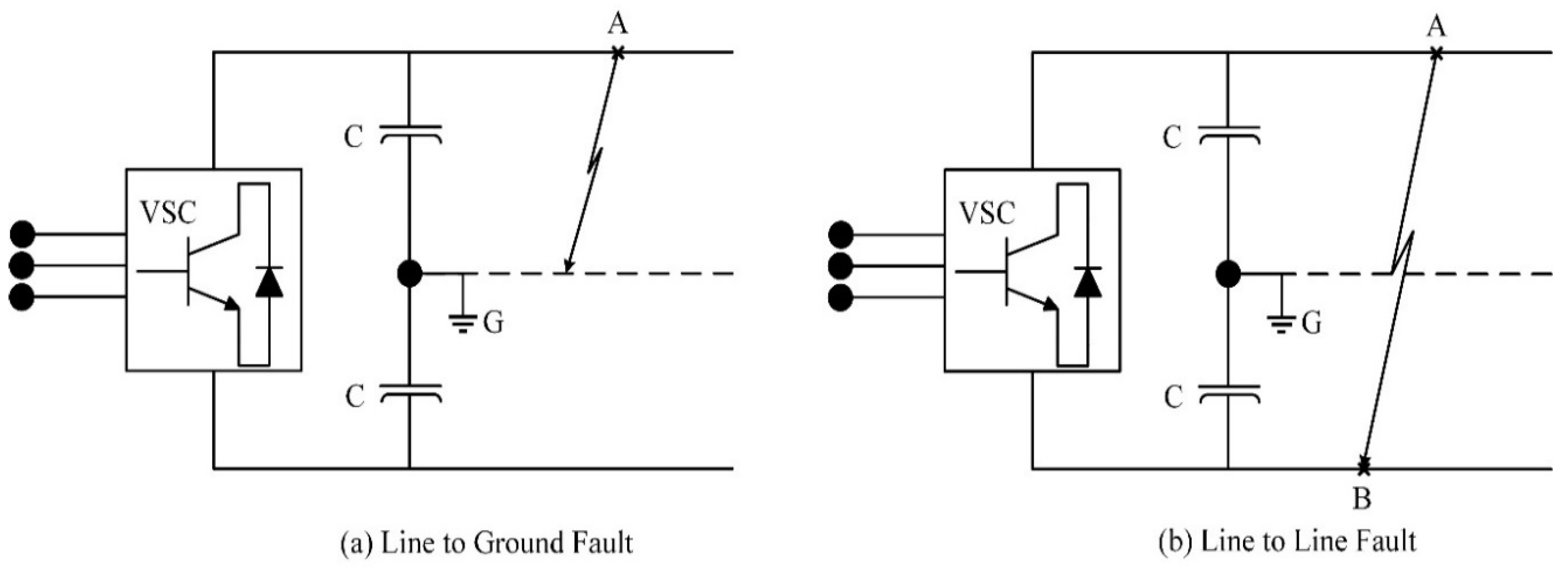
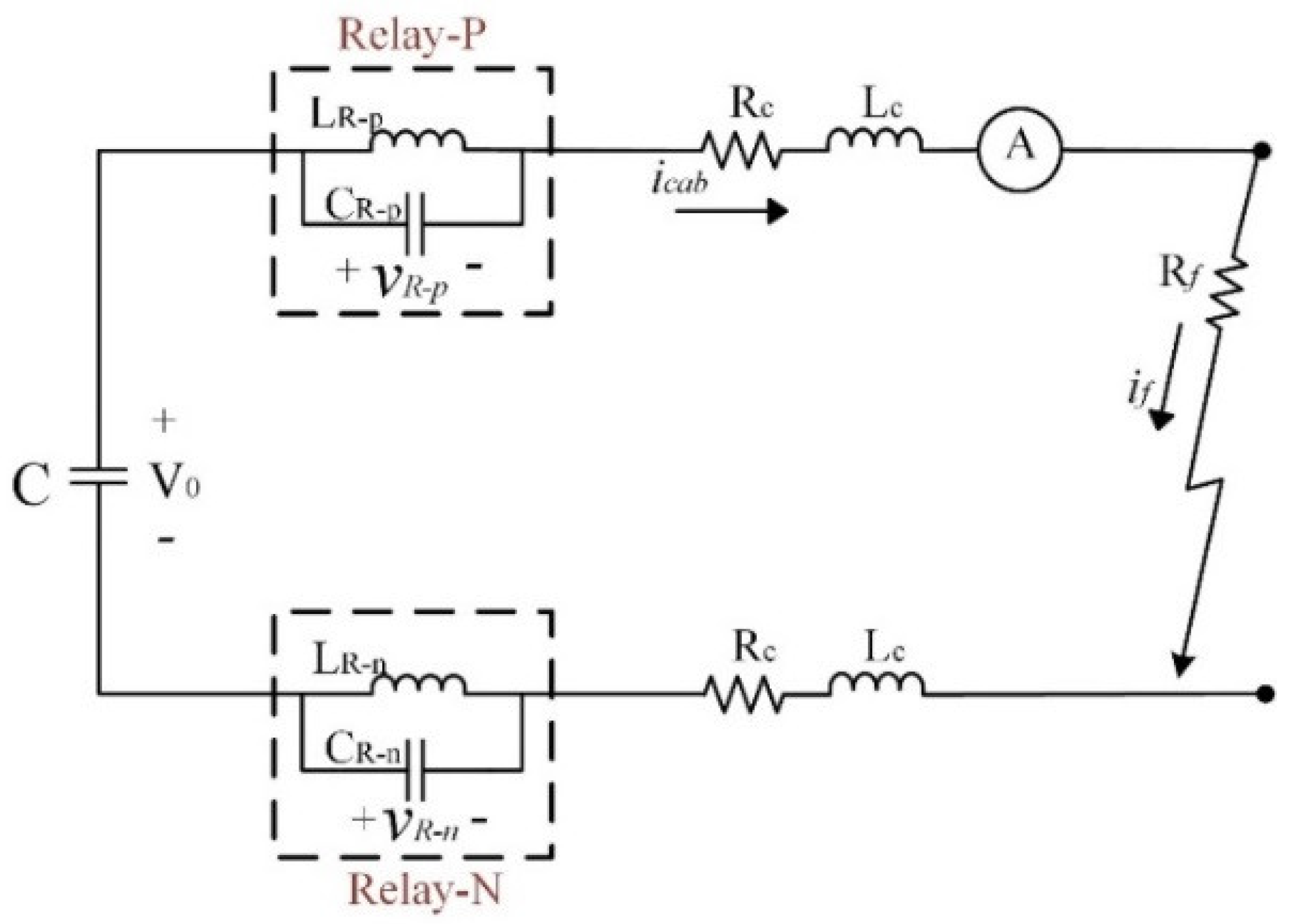
2.2. DC Fault Types and Fault Characteristics

Understanding system behaviour under various fault conditions is essential for developing an appropriate protection strategy. This section defines possible fault types in DC Microgrids and illustrates the post fault response of the system.
The network fault in a DC system can be categorized into 2 types: short-circuit fault and open-circuit fault. Considering the commonly implemented real-time hierarchical voltage control strategy, open-circuit is more of a control strategy issue rather than protection; hence not in the scope of this paper. Generally, there are two types of short-circuit faults in DC systems: (a) Positive to negative Pole short circuit fault (pole-to-pole fault) and (b) Positive or Negative Pole to ground fault (Pole-to-ground fault). Though the post-fault voltage profile may vary significantly in these two types; the nature of the short circuit current is largely similar for both types of short-circuit fault.
Apart from the fault impedance itself, the location of the short-circuit point may significantly affect the post fault behaviour as the feeder impedance between the fault point and source often plays a significant role to bring down the transient fault current. For example, the fault originating at the main bus produces higher transient current which usually posts the most severe threat to the network as the fault loop impedance contributed via the feeder line is minimum [25].
Fault current analyses for each located fault is crucial for designing a protection system as well as maintenance and post-fault restoration [26]. As all sources contribute towards the total fault current in the network, their participation, in addition to the control during the transient, also heavily relies on the actual impedances between the respective source and the fault locations. For elaboration, consider the (pole-to-pole) bus fault in a single bus DC system as shown in Figure 5 (b). The transient fault current from point A to B is caused by the immediate current discharging from the converters smoothing capacitors. Contribution of this fault current from the capacitors can be demonstrated by (1), [27]:
i c a p ( t ) =   v d c R c a p   ( e t / τ d   )
where v d c denotes the voltage at the dc bus when fault starts, R c a p is the capacitor series resistance and τ d = C d R c a p represents the time constant of the converter and dc bus RC system. Moreover, cable impedance should be incorporated in calculation if the cable length from converter to the dc bus is considerable which would result in a higher order dynamic system [27]. Similarly, if the feeder fault is initiated, the immediate fault current contribution towards the feeder fault can be obtained by considering the overall effective impedances [28]. Hence, total fault current between the short-circuited conductors can be evaluated by adding all the currents contributed to the fault current as [25]:
i f ( t ) =   k = 1 n i s , k ( t )
where k is the number of sources connected to the dc bus. Similarly, in those cases of poles-to-ground fault, the system principle of fault current contribution is the sum of the contribution of all connected sources; however, the paths of fault currents are heavily dependent on the earthing configurations.
Apart from the capacitor discharging current during fault, source side contribution towards the fault is another important factor needs to be considered while developing a fault locating criteria [29]. Source side contribution is highly dependent on the converter technology type, either non-isolated or isolated, being used in DC Microgrids [29]. Commonly suggested non-isolated type of converters for LVDC systems are two or three level voltage source converter (VSC), neutral-point-clamped (NPC) converter and modular multi-level converter (MMC) [30,31,32,33]. Short-circuit fault currents in LVDC systems based on VSC interfacing to AC-grid side can be divided into three stages, (1) capacitor discharge stage, (2) diode free-wheeling stage and (3) ac-side contribution stage. All the three stages during short-circuit fault is elaborated in Figure 6.
Then, the response of the system under all these stages (assuming the fault initializes at t o ) can be approximated as follows:
Stage 1 :   v c =   V o ω n ω e α t S i n ( ω t + σ )   I o ω C e α t   S i n ω t
i c a b =   C d v c d t =   I o ω n ω e α t S i n ( ω t σ )   V o ω L c a b e α t   S i n ω t
where α =   R c a b / 2 L c a b ,   ω 2 =   ( 1 / L c a b C ) ( R c a b / 2 L c a b ) 2 , ω n = α 2 + ω 2 , and σ = tan 1 ( ω / α ) .
Stage 2 :   i D =   I o e ( R c a b / L c a b ) t
Stage 3 :   v g a = V g S i n ( ω s t + β )
i g a = I g S i n ( ω s t + β ) + [ I g o S i n ( β o ) I g S i n ( β ) ] e t τ
where V g is the voltage at grid, ω s is the angular frequency, = t a n 1 ( ω s   τ ) , τ = ( L c a b / R c a b ) and β is the voltage angle at phase-a.
System’s response for NPC converter-based connection shows the similar behaviour as in the case of VSC under pole-to-pole short-circuit faults. Equivalent circuit of NPC converter is shown in Figure 7. Fault level controllability is quite limited for NPC type converters. Whereas, MMCs can provide enhanced fault controlling and resilient operational capabilities for LVDC systems [34,35]. The use of H-bridge sub-modules can enable a full blockage against the fault current [36]. Hence, these types of MMC with H-bridge configurations are capable enough to block AC side contribution under DC pole-to-pole fault conditions.
The requirement of limiting post-fault contribution from the source, balancing power flows, dc-bus voltage regulation and appropriate AC-DC-AC bi-directional interfacing conditions for LVDC systems led to the development of isolated converters [37]. Some of the most commonly considered isolated converters are dual active bridge (DAB) converters [38,39,40,41,42,43], isolated boost and phase-shift full bridge converters [44,45,46]. Isolated converters, for example DAB converter topology, have a simple structure with soft switching characteristics, which is shown in Figure 8. Due to the presence of galvanic isolation, the source side fault current is blocked upon a fault on the DC network side [47].
Apart from sophisticated converter architectures, the source side current contribution can be blocked by source side protective devices or converters with modified semiconductor devices. Installing single electronic switch along with fast mechanical disconnector or by replacing antiparallel diodes with GTO’s are some of the techniques suggested for blocking source contribution for fast DC fault isolation [48,49].
The fault current contributed from source side can be significant upon a DC fault. The use of extra semi-conductor device and/or galvanic isolation can effectively block fault current contributed from the source side though; it will normally introduce extra conduction loss.

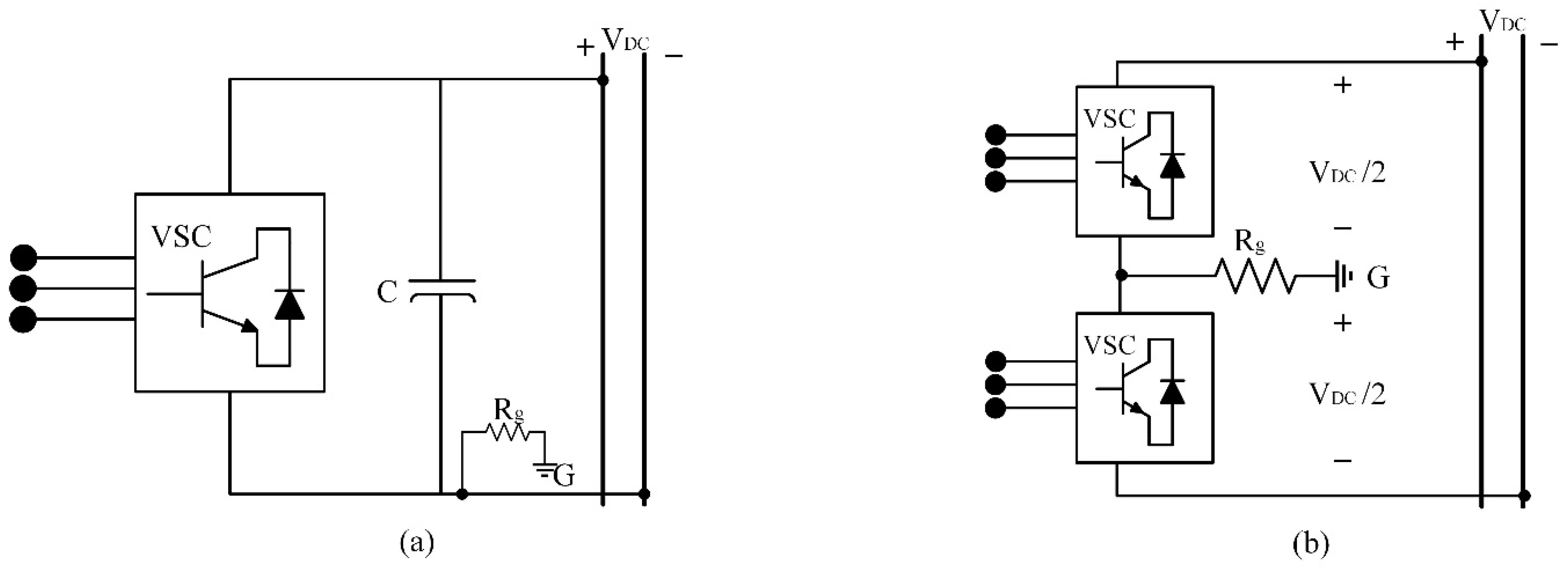
2.3. DC Earthing Configurations

Earthing is one of the key factors in a dc power networks which highly influence the transient fault current, over-voltage and the protection settings of the system [25]. Carefully designed earthing configuration helps in detecting the ground fault, minimizes the stray currents and provides safety to personnel and equipment [50,51,52,53]. For LV DC power system, earthing schemes can be categorized into the following types, that is, (a) Unearthed System, (b) Resistance earthed system and, (c) Solidly earthed system.

2.3.1. Unearthed DC System

Unearthed DC system provides better reliability of power supply as compared to other earthing configurations because it can allow the system continue its operation for a moment when single line to earth fault occurs [54]. Due to very low earthing current, pole-to-ground fault is difficult to be detected using fault current detection only [55]. In addition, unpredictable DC voltage offset in the presence of small leakage current is another shortcoming for such earthing configuration [56]. Moreover, problem of electrical noise in the entire system can be encountered, which may disrupt signals resulting in missing pulses. Additional insulation may be required to withstand the uncertain potential between conductor lines and earth, which increases the cable cost, weight and footprint as compared to other grounding configurations [57].

2.3.2. Earthed DC System

One option for DC earthing is to earth one pole via a certain amount of impedance, that is, resistance, which is illustrated by Figure 9a, where at the negative pole of a VSC-based terminal is earthed via a resistance. On the other hand, earthing can also be achieved by connecting the neutral point between the converters to the earth point through resistance, as shown in Figure 9b.
Resistance earthing is often configured without neutral point and is practically implemented in some early-stage VSC-based High Voltage DC (HVDC) systems [58,59]. If a DC power system is earthed at the neutral point, a bipolar system is formed; therefore a large earthing resistance can be used to limit the power losses during normal operation [60].
In general, neutral point earthing scheme is used for reducing ground potential against live conductors hence improve personnel safety and relieve some stress of insulation during normal operation [61]. It can also minimize the circulating current with respect to ac-side neutral grounded system, which helps to suppress the current and voltage transients during a pole-to-ground fault [62]. However, fault measurement and detection becomes challenging for small ground fault currents which may energizes metal enclosures of loads. Equipment insulation requirement becomes higher than normal condition during a pole-to-ground fault as it has to withstand the full bipolar DC voltages before the fault is isolated.

2.3.3. Solid earthed DC system

Solid earthing is the concept of connecting any of the DC poles to the earth without any (or very small) impedance in between. To solidly earth the Bipolar DC (BPDC) system, middle point between the two poles is electrically connected to the ground point as shown in the Figure 10. Solidly earthed scheme produces larger ground current and higher voltage transient than other earthing schemes [63]; hence successful detection of such fault becomes relatively easier. The insulations required for equipment and the cables is to withstand half DC pole-to-pole voltage, which reduces the overall systems cost, space and weight.
Solid earthing can also be implemented in monopole DC power grid by connecting negative pole to earth but it has been reported that leakage current can be 30 times greater than unearthed in traction systems [36]. Solid earthing is not suggested to be used in modern power systems due to its major drawback of corrosion and safety issues [49,50].

2.4. Circuit Breaker Technologies

To isolate a fault, suitable protective devices are required by regulation. Lack of natural zero crossing and high current changing rate (di/dt) are the major challenge to disconnect an LVDC fault circuit. This makes DC current interruption more difficult, thus, bringing consequent challenges for designing DC circuit breakers (DCCB). Appropriate design and implementation of circuit breakers is a fundamental requirement for developing the protection scheme for DC power system.
Various DC circuit breaking and fault limiting technologies have been developed, implemented and analysed in different DC applications. This section examines and evaluates these DC current breaking technologies with respect to their design, time of operation and power losses.

2.4.1. Mechanical Circuit Breakers

Mechanical circuit breakers are widely used as a protective device in most AC systems and LVDC systems. To further assist opening an DC circuit, the tripping device in conventional Moulded-Case Circuit Breakers (MCCB) are proposed to operate with resonance circuitry to generate zero crossing [64,65,66,67]. Basic configuration for such kind of implementation is shown in Figure 11. As the MCCB switch opens after the fault current detection, resonance circuit can generate a negative transient current to counter the fault current flow in the main circuit. As the negative current grows, it may eventually become greater than the fault current when a zero-crossing is created. Thus, the fault current can be interrupted with MCCB [68]. These types of MCCB are known as passive resonance DCCBs. Based on similar principles to create zero-crossing, active MCCB configuration adds an additional switch and pre-charges the capacitor to excite the resonant circuit [68]. This can accelerate the rise of the resonance current, eventually leading to a faster operation of MCCB. An active resonance MCCB configuration is illustrated in Figure 12 [69].
Though the mechanical circuit breakers are considered well-developed and in general mature in low voltage sector, their fault interruption time is typically as slow as 30-100 ms [70]. Such low operating speed limits their usage since a DC transient current can reach its peak value up to tens of the nominal value in a few milli-seconds, the application of mechanical circuit breaker requires system be able to withstand a let-through energy (i2t) over longer time comparing with those DCCBs that can operate faster (when no fault current limiting measurement is carried out).

Commercially Available LVDC Circuit Breakers 

With a rapid development of Photovoltaic (PV) generation, a range of mechanical CBs suitable for LVDC have been commercially available in the range of 500 VDC to 1000 VDC, can be seen in References [71,72]. PVGard DC circuit breakers are available for 500 VDC & 1000 VDC with an interrupting capacity ranging from 1.2 kA and 7.5 kA [71]. Both have the ability to open on signal from DC arc or ground fault detector.
ABB offers a wide variety of circuit breakers for the DC overcurrent protection of LVDC Microgrids falling in the category of air type circuit breakers (ACBs), miniature circuit breakers (MCBs) and moulded-case circuit breakers (MCCBs) [72]. ACBs are from Emax-series having breaking capacities from 35kA to 100 kA operating at 500, 750 and 1000 VDC. SACE Tmax T-MCCBs series typically for 500, 750 & 1000 VDC having breaking capacities up to 150 kA. Then, MCBs series of S200M UC, S800 UC and S800 PV are also available starting with rated operational voltage of 220 VDC to 1200 VDC. The short-circuit interruption capacity ranges from 5 kA to 10 kA in such breakers [72].

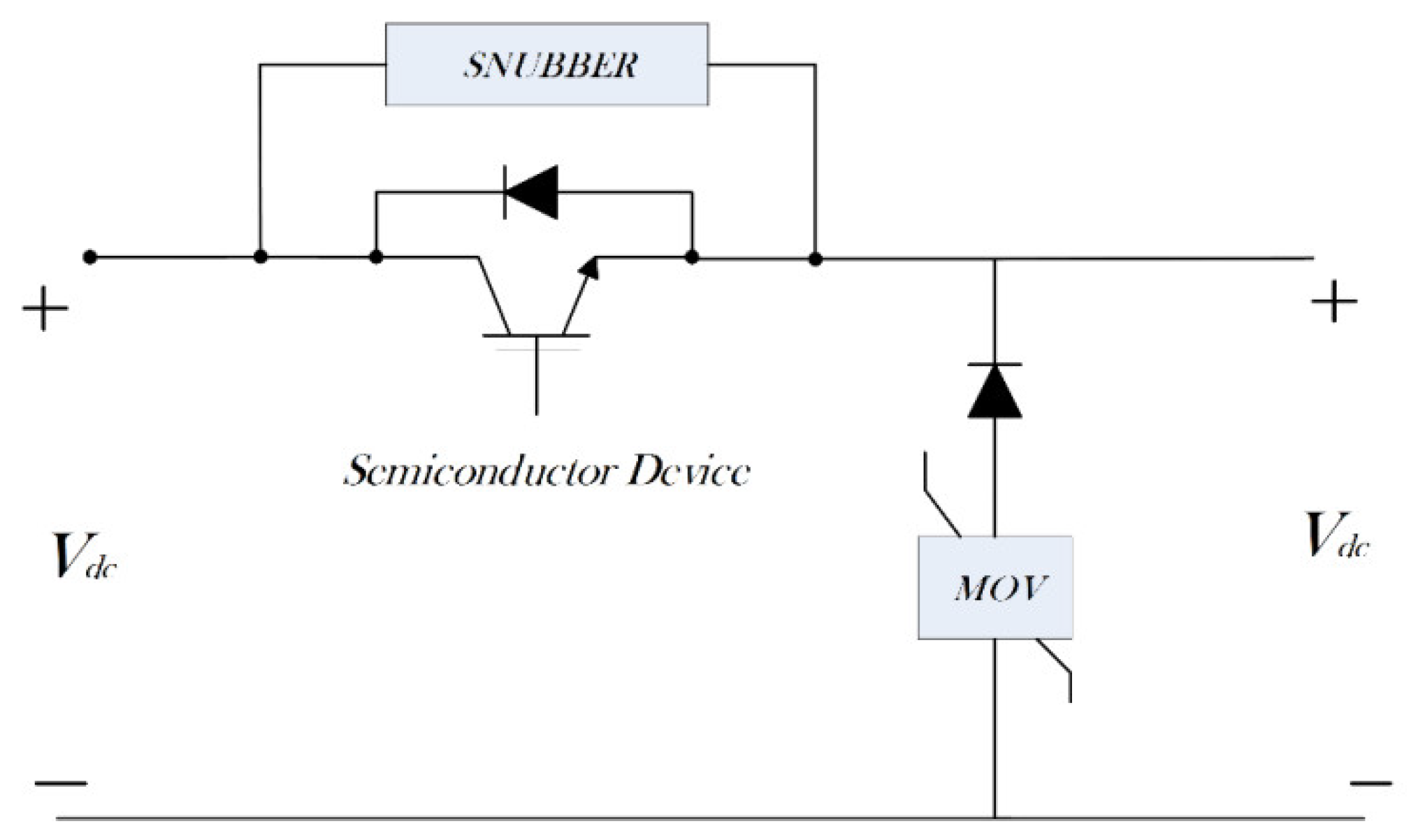
2.4.2. Solid-State Circuit Breakers

Since the inherent time delays in tripping and the overall protective operation with slow-reacting fuses and mechanical MCCBs limit the protective performances, power electronics-based protective devices have been developed for DC applications. Such devices are generally referred to as Solid-State Circuit Breakers (SSCBs) [73]. SSCBs are based on semiconductor devices, such as Insulated-Gate Commuted Thyristor (IGCT), Insulated-Gate Bipolar Transistor (IGBT) and Gate Turn-off Thyristor (GTO) [74]. These types of CBs require an energy dissipation element to be attached in the circuit so as to prevent the pulsing energy from damaging switching devices. Generally, those energy dissipation elements are Metal-Oxide Varistors (MOV), capacitors, switched resistors and combinations of them [75,76].
Various SSCBs configurations have been proposed for DC protection with their own pros and cons [77]. SSCBs started with simple architectures for unidirectional power flow which stem from the circuitry illustrated in Figure 13.
As shown in Figure 13, a surge arrester branch (i.e., MOV) is connected in series with a free-wheeling diode which is connected in parallel to the DC bus. Under normal conditions, semiconductor device remains on and load current flows through it. When a fault is initiated, the semiconductor turns off and the fault current is forced to commutate through the free-wheeling diodes with the surged energy captured by the MOV [78]. Since there is only one fully controllable semiconductor device, such CB structure is for unidirectional only. As an enhanced version, bi-directional SSCB, is proposed thereafter, which is illustrated in Figure 14 [79]. As is shown in Figure 14, two unidirectional SSCBs are connected in “anti-series” directions so the current flowing in both ways can be switched off. Enabling bidirectional operation, such structure also introduces twice as much as the conduction losses during-steady state operation for unidirectional SSCB.
Very fast operating time within 100 micro-seconds is the key advantage of SSCBs which enables the system with fast fault isolation capabilities. However, considerable conduction losses in SSCBs in steady state condition are the major drawback, which is more significant in LV systems since the conduction voltage drop of a semiconductor is more considerable with the respect to the nominal voltage level.

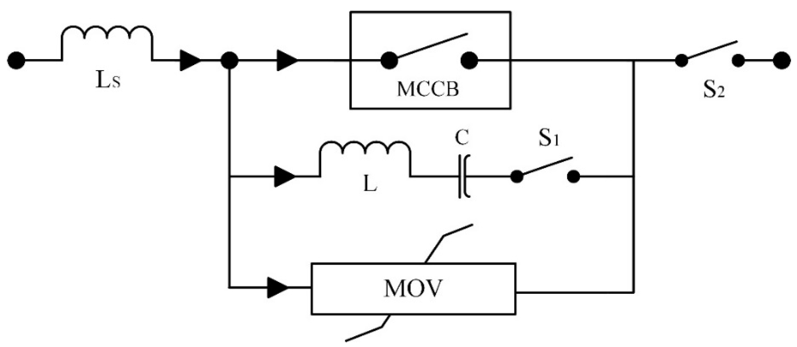
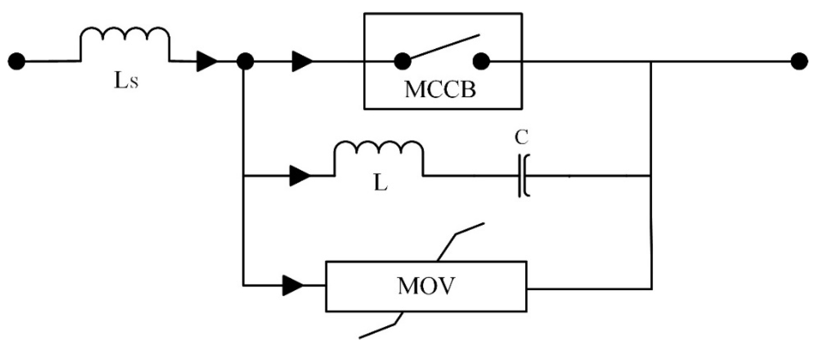
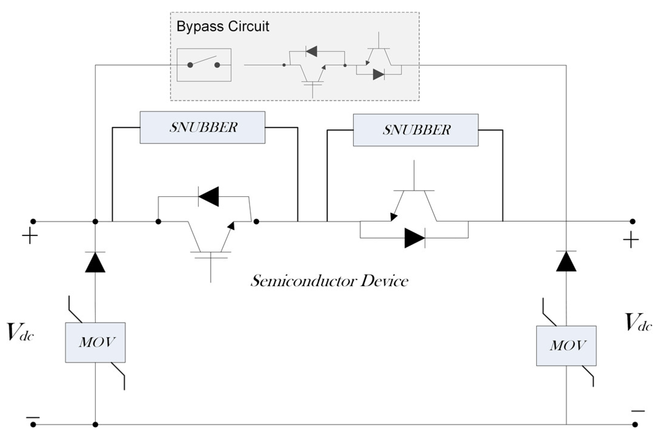
2.4.3. Hybrid Solid-State Circuit Breakers

In order to reduce the conduction losses in the main circuit, the concept of Hybrid Circuit Breaker (HCB), introduces a bypass branch mechanical switching devices to allow steady state current to pass through, which is illustrated in Figure 15 [80].
As is illustrated in Figure 15, all the current flows through bypass branch whereas current remains zero in the main branch under normal conditions. When a fault occurs, fast mechanical switch (or CB) opens and the fault currents instantly gets commutated to the main SSCB by load commutation switches [81]. Hybrid SSCBs have been modelled for 320kV (or higher) HVDC systems, which boasts an operational time of less than 5ms [80]. Combining the strength of mechanical CB and SSCB, the concept HCBs are not being generally used and developed for LVDC applications due to their high complexity and the inherited costs.

2.4.4. Fault Current Limiters

Fault Current Limiter (FCL) is a device that can instantly suppress transient fault current as well as the rate of current rising so as to assist circuit breaking [82]. FCL helps to reduce the required rating of the circuit breaker and brings down electrical stresses on the system components under faulty conditions. Therefore, FCLs potentially provides an opportunity to handle the problem of those most severe fault scenarios within DC systems. Generally, two different methods for limiting current transients have been developed: resistive based and inductance based FCL [83].
Inductive FCL can effectively reduce magnitude and the rate of change of transient current with insignificant steady state losses [83]. However, it may increase the energy that can contribute to fault current, which results in higher energy dissipation requirement for circuit breakers. On the other hand, resistive FCL have the ability to limit both continuous as well as transient DC currents within the system which introduces additional losses within the system. To avoid additional losses under steady state operation, resistive superconductive FCLs (SFCL) are designed to limit fault current. The resistance of SFCL can be increased immediately when it is triggered upon reaching the current and/or thermal threshold [83,84,85,86]; whereas the resistance value can be limited to minimum level during steady state under the condition of a very low ambient temperature.
Though SFCLs are compact and simple; their inability to withstand high voltages is one limiting factors against the application of SFCLs to DC systems. More importantly, SFCLs normally require extra power to maintain a low ambient temperature for the superconductors, which again will degrade the system efficiency. Further, although the design of SFCL has been considerably improved in recent years, it is still considered as immature and costly compared to other technologies used for LVDC protection.

3. DC Fault Detection, Location and Isolation

Detection, location and isolation of DC fault are three key aspects to be considered while designing a protection scheme for DC relays. During the design process, the specifications of bus configurations and earthing schemes has to be considered [49,87,88,89,90,91,92]. In this section, a review of DC microgrid protection schemes is carried out with respect to their capability and performance in these key aspects.

3.1. Local Measurement Based Fault Detection and Isolation Schemes

In order to achieve the fastest fault detection without any communication delays or consequent reliability issue, detection based on local measurement is an immediate thought. The schemes using local measurements are usually known as non-unit-based schemes. Such non-unit protection scheme is commonly implemented with pre-set threshold values. By building up the relationship between faulty conditions and certain electrical properties with mathematical modelling, thresholds are selected to set up the operating criteria. The electrical properties can be used to set up thresholds typically include overcurrent, overvoltage, under-voltage, di/dt, dv/dt and the impedance [49]. As soon as the measured value reaches the threshold, the protection system operates. Non-unit protection schemes are not capable of protecting a specific zone of the DC microgrid. However, these schemes have the ability to coordinate among the complete protection system and can be effectively used for back-up protection in the network [87].

3.1.1. Overcurrent Detection

Detecting fault by using the overcurrent principle is one of the most common protection strategies in AC distribution networks. Unlike the direction current magnitude detection for AC overcurrent, the methods of DC fault current detection vary. By detecting an instant overcurrent, the protective operation is tripped. The main challenge is that when the fault loop impedance is large, the sensitivity might be degraded. Therefore, overcurrent criteria is proposed along with under-voltage measurement [48]. Such fault detection scheme can provide fast response to a severe fault that is closely located to the relay, though; insignificant fault discrimination is provided. If the uncertainty of fault impedance is not fully considered in this method, it may result in unnecessary tripping of non-faulty sections and lead to a lower reliability. In order to improve the detection of large resistance fault, overcurrent detection has also been proposed by injecting LC circuit in series to the system, which is shown in Figure 16 [88]. The injected LC circuits can create voltage signals of different frequencies depending on the value of the fault resistance, which can be extracted by wavelet analysis; thus, large resistance faults can be detected. This protection technique requires the data acquisition over a certain amount of time with a relative complex mathematical calculations. One potential risk is that the introduction of LC circuit in to the main circuit may give rise to undesirable dynamics against stability.

3.1.2. Derivative Measurement-Based Fault Detection

One derived fault detection scheme based on DC current profile utilizes the measurement of derivatives of current and/or voltage profile. Such scheme has been suggested and analysed on a DC ring bus topology, where the DC microgrid is divided into different zones. The rate of current change(di/dt) is measured for each zone and the highest value of di/dt is used to detected and located the fault [91].
Further investigation on di/dt and dv/dt under fault conditions illustrates that the rising time of di/dt to reach its peak value after a fault is not sensitive to the variation of fault resistance and neither is du/dt [93]. This means that the oscillation frequency of di/dt and du/dt signals can be useful to detect the fault location.
This technique can be used for fault detection in general but the fault cannot be located accurately and requires fast duplex communication channels among all the relays [87]. In real practice, the accuracy of the indirect measurement of di/dt and dv/dt can be affected by the measurement noise introduced from the current/voltage sensing devices, which might, in turn, undermine the overall protection performances.

3.1.3. Source Current Blocking Protection Scheme

Since the fault current contribution from the terminal sources are considered to be the major support to a sustained DC fault current, blockage of current from all electrical sources in a DC network is considered to be a safe way to regulate DC fault current so as to allow the isolation of DC faults during the blockage period. Therefore, a fast DC current blocking approach, known as the “handshaking” DC protection schemes is proposed [74]. Based on a scenario that a DC grid is energized by AC sources via VSCs, it utilizes the conventional AC CBs on the AC sides to block the source of fault current when a fault is detected [92]; hence the DC protections are carried out by the cooperation of low-cost DC switches for isolation and AC CBs to cut-off the sustainability of fault current [92]. By disconnecting all the energy sources, the need for DCCB is not necessary to reconfigure the DC network. After all AC CBs are open, the fault detection approach can be divided into two steps. Firstly, to disconnect all the DC switches for the potentially faulty lines by selecting the appropriate faulty line and secondly, to identify the fault line by reconnecting the DC switches for the healthy part for system restoration from one line to another [92].
This method is reliable for identifying and isolating faulty line in multi-terminal DC systems. The identification of faulty line based on local measurement makes it cost effective and less complex which requires no communication network. However, it compromises the selectivity by producing a prolonged shutdown by momentarily de-energizing the entire network, which can significant downgrade the power distribution reliability in a distribution network [94].

3.1.4. Voltage Prediction-Based Protection

Voltage prediction-based protection method has been proposed for DC ring bus topology. Fault detection and its isolation is achieved by finding the difference between the expected normal conditions and measured values in an event of a fault [95,96]. The technique is implemented by using local measurement and estimate the normal voltage value at the relay point by using a developed mathematical model which is used to interpolate/predict the next data value. The prediction of the voltage is based on previously sampled values. It can result in large deviation between the measured and predicted voltage values during a fault. However, the voltage difference becomes insignificant when the fault loop impedance is high [95]. Such method also heavily relies on the accuracy of the mathematical model used. This may result in malfunction of the relays and protective devices when the fault location is far or with large fault resistances.

3.1.5. Oscillation Frequency-Based Protection

Fault detection and selectivity scheme based on oscillation frequency and power calculations of the first transient cycle of fault current is proposed to be employed in such scheme [97]. The local measurements are used to calculate the oscillation frequency and associated transient power as soon as the disturbance in current is detected. Intelligent electronic devices are used to record the oscillation frequencies at both ends of the line where they compare the measured oscillation frequencies with the threshold and confirm a fault’s occurrence when a threshold is reached. Transient power calculation is used to select the faulty line in the system. Despite the fact of its fault detection and appropriate fault selection capabilities, the protection method requires fast communication between intelligent devices to make decisions before fault isolation. Further, the determination of the threshold frequency heavily relies on the accuracy of the transient model of the faulty system. It could be very difficult to obtain the threshold frequency that can correctly tell a fault happens in a complex system with various types of converter architectures and non-linear post-fault responses. These together limit the practical implementation of such methods for DC Microgrids.

3.1.6. Differential Protection

Differential protection detects fault based on the difference in current magnitudes and the relative directions on both sides of a specific component within a system [29,87,98,99,100]. Consider that the current flowing into the protected component as i o , out from the component in. The difference between both currents is: Δ i = i n i o .
As a fault current occurs at the middle of protected component, Δ i , becomes greater than a threshold value, the occurrence of fault is detected and then suitable signals will be directed towards the protective devices to isolate the fault.
Since such method is able to tell a fault without the information of loop impedance, it has been proposed for all kinds of system topologies including ring type DC bus system [24]. With this method, DC faults can be detected with synchronous data detected from the Intelligent Electronic Devices (IED) installed by both ends of the protected component. This can be further explained by Figure 17. Differential current passing through devices helps to detect the fault and can be isolated quickly. On the other hand, in case of operation failure, IED sends configured signals to neighbouring IEDs to operate their adjacent CBs as a backup protection. As a result, faulty section can be isolated without shutting down the healthy sections [24,81].
This protection technique is reported to be quite effective because it detects fault by only observing the relative change between the inputs and output current of the protective component irrespective of fault impedance and fault current magnitude [99]. Comparing with other protection scheme that requires global data acquisition during a fault, the fast communication of this scheme is only required between the neighbouring relays, which improves the reliability.
Current measurement synchronization for high di/dt in LVDC systems is the major challenge for such scheme. It has been reported that Δi should be ideally zero for any external fault; however, it is found that the time delay, Δ t between the measurements of in and i o will lead to a non-zero differential sum and consequently can cause relay malfunctioning [101]. Further, in extreme circumstances, a small time delay, for example 10-µs, can cause a significant error, for example 75%, of the fault current in the calculation of Δi when the fault occurred out of the protected zone [100]. To mitigate the issues brought by asynchronous communications, sensory networks are suggested [102], which add up to the complexity and hence the difficulty of the practical implementations.

3.1.7. Artificial Inductive Line Impedance (AILI) based Protection

Event based fault classification method has recently been developed by combining non-unit and unit protection techniques [103]. This method utilizes artificial inductive line impedance (AILI) in each feeder of DC ring bus system to identify fault type with the help of di/dt values. To be more specific, fault types are categorized as: a bus fault, an interconnected fault or adjacent feeder or a bus fault. The protection method is based on three stages that is, classification of fault, identification of fault and finally the isolation of the fault. It is reported that the suggested technique can isolate the fault within 30 ms [103]. There is no fast communication and synchronization required between the units and less data is transferred as compared to differential protection scheme.
Specifications for the sources attached are given in detail; however, the cable impedance and its length specifications are difficult to design. Inaccuracy and difficulty for classifying high-resistance fault is the major drawback of this method which may limit the feasibility of this protection scheme.

3.1.8. Summary of DC Fault Detections and Isolations

Techniques discussed above for detecting and isolating fault generally rely on communication among protective devices. Such techniques divide the network into zones and sends signals to the devices in other zones, where it tries to detect the faulty region accurately and isolate it. However, this communication among the devices introduces operational delays in fault detection and isolation which makes the protection critical in such cases.
Based on the investigation above on different protection schemes for LVDC distribution system, their working principles, operating times, functions and applicable conditions are summarized in Table 1.

3.2. Fault Location Schemes

Locating fault accurately is one aspect of a protection system for timely maintenance and system restoration to increase the resilience of a DC microgrid.
In general, the techniques of fault location can be divided into two types: online methods and offline methods. Most of the existing techniques for locating fault primarily are based on offline based methods [24,104,105,106]. These methods usually employ a probe to inject current or voltage signals to the main circuit and identify the fault location by detecting the electrical response to the injected signals. Obviously, extra operating time and manual intervention are required for the offline method. To reduce the level of human invention and accelerate the post fault maintenance, online methods are proposed. This subsection analyses different offline and online methods and examines the accuracy of the different developed techniques.

3.2.1. Offline Fault Location Methods

(a) Active Distance Estimation-Based Technique
Distance protection scheme works on the principle of estimating the distance from the protective device to the fault by measuring the short circuit reactance based on predefined frequencies. Such methods are widely used for AC systems protection; however, very small series cable inductance in DC systems creates a main challenge for this method to be used for DC systems. Moreover, the term of fundamental frequency is no longer a predefined default value to define the impedances of a DC system in transient [81].
Deriving from similar concept of distance protection of AC systems, active distance estimation methods for DC Microgrids protections are proposed [24,107]. In such methods, power injecting unit (which is named as a probe power unit) is employed to inject low-power current or voltage signals of predefined frequency spectrum to the faulty loop. The voltage/current responses of the signals are sampled and analysed to estimate the fault distance to locate the fault. To implement, active distance relays usually incorporate a low power electronics converter as the probe unit to generate the intended signals. Voltage or current signals with various magnitudes and frequencies can be generated by these units using full-bridge or half-bridge architectures as shown in Figure 18a [106]. The injection unit can be embedded into the main DC circuit and share the passive components to save the cost, which is illustrated by Figure 18b [24,104], where the probe circuit is open during normal operation.
Signal processing analysis techniques, for example Fast Fourier Transform (FFT) and least square curve fitting, are used to extract the information of the fault impedance from the post-fault data acquisition over a certain amount of time. Using the mathematical relationship between the fault location and the fault impedance, the distance between the relay and fault point is estimated [47,48]. Sensitivity of fault location estimation is highly dependent on the mathematical relationship developed. Therefore, it is essential to carefully consider all the variables and dynamics of the system during fault transient. This is further elaborated and explained by comparing different research works carried out in Ref [24] and Ref [107] which uses the same methodology. It is assumed the natural frequency of the system to be equal to the damping frequency of the injected current which is not true and also ignored the damping co-efficient of current in calculation; whereas, Ref [107] tried to consider all the dynamics and variables of the system under fault conditions. Table 2 compares and analyse the variations in fault distance estimation error by both the methods when a pole-to-pole is created, where E1 and E2 represents the percentage estimation error by the methodologies adopted by [24,107], respectively. The comparison shows that it is essential to consider all system dynamics for developing any mathematical relationship for estimation or system modeling.
Ideal enough for a simple DC system as point-to-point, one single probe unit (as mentioned in Figure 18a) cannot clearly tell the remote fault location when there is a more complicated circuit on the far end. To locate the fault in a relatively complex system topology, the DC system is suggested to be divided into different zones where one probe is assigned to each of the zones independently. Even though the active distance protection demonstrates comprehensive information about the state of the system. The requirement of probing arrangement with signal injection and high bandwidth measuring unit for each node increases the protection system cost. The interaction between different probes and a more sophisticated DC system topology may significantly add up to the complexity of such scheme.

3.2.2. Online Fault Location Methods

(a) Derivative Based Technique
To provide faster fault location, online methods to estimate the fault location are proposed by measuring the voltage, current and di/dt values in a transient stage locally in a radial DC distribution system [108,109]. These methods are based on developing linear relationship between di/dt and the fault loop impedance. Fault inductance from the protective device to the fault point is estimated by using these measured values for distance estimation. The suggested time for fault detection and location estimation is assumed theoretically, for example in less than 0.65 ms with an error of less than 20% to effectively build up the linearized relationship between di/dt and the fault location. It is quite critical to establish an accurate transient model to minimize the fault locating error. This inaccuracy is added due to the non-linearity of the converters under fault conditions which introduces more complexity in the system evaluation. Time to locate fault, distance estimation error and DC microgrid modelling inaccuracies make this method difficult to be generically applied to a multi-terminal DC Microgrids with various converter topologies [91].
(b) Noise Pattern Analysis-Based Technique
Locating earth fault in unearthed system is one of the major difficulties in DC Microgrids. This is due to the insignificance of fault current under such faulty conditions. Most of the fault locating techniques cannot locate pole-to-ground fault for unearthed system. To address this issue, pole-to-ground fault locating technique based on Multi-Resolution Analysis (MRA) using wavelet analysis is proposed [110,111]. MRA is a technique used to extract significant features from the signal with higher resolution [112]. By analysing the electrical noises over a period of time, wavelet analysis technique is used to recognize inherent high frequency noise patterns. Presuming these specific patterns are introduced by interaction of parasitic inductances and capacitances with the switching patterns of power electronic devices, the information of earth faults can be extracted from the analysed feature of the noise signals. This method does not require any additional signal generating equipment, voltage or current measurement or communication among devices.
Nevertheless, the technique is suggested to work under the following conditions: (1) The system is unearthed or having very high impedance; (2) Creates a circuit loop with parasitic circuit elements through earth; (3) The presence of an excitation in the ring circuit; (4) Fault signal characteristics should be significantly relevant to fault location and (5) Noise signal should be measurable [110]. For a DC microgrid with a relatively sophisticated structure, for example a system with multiple terminals, various types of converters and variable switching frequencies, the fore cited conditions may become quite demanding to completely fulfil.
(c) Voltage R esonance-Based Technique
For VSC-based DC system, voltage and current resonance are initiated by the discharge of terminal capacitors after a short-circuit fault [111,113]. Such resonances can go through VSC-link capacitor, cable resistance, cable inductance and fault resistance and form an RLC resonance circuit in fault transients. By defining a relationship among the cable parameters (i.e., cable inductance and resistance) during the resonance behaviour of the circuit, a voltage resonance based fault location scheme can be developed [113]. Such scheme develops two separate relationships under solid fault and resistance fault conditions. Then, Prony’s method is applied to solve the transient circuit based on the RLC circuit. These results of the impedance values are then used to estimate the distance of fault location. Though the method does not use any communication links for fault location estimation, the accuracy still relies on the accuracy of the linearized RLC modelling and its consistency to the data acquisition.
(d) Transient Peak Current Based Technique
Given the fact that the values of both transient peak current and steady state fault current are closely relevant to the fault impedance, they are suggested to be used for online fault location as well. By developing a linear relationships among dc side resistance, inductance and transient peak current over a prolonged process of post-fault oscillations [114], the total inductance in the loop can be obtained. As a drawback, the use of steady-state current profile also implies that the semiconductor devices have to be able endure a let through energy (i2t) for longer time, which requires the ratings of the semiconductor and/or the fault current limiting devices be sufficiently large to survive after those most severe faults.

3.2.3. Summary of Fault Locating Techniques

Locating fault accurately with less network shutdown time is still a challenge. As various researchers have developed offline techniques for locating fault where all of them requires a separate signal injection unit (probe unit). These signal injection units add extra cost and increases the additional delay in the restoration of the network. Whereas, online methods for locating fault depends on the accurate circuit modelling of the system by considering the system’s dynamicity under fault conditions. Therefore, online techniques developed till date are not matured enough for their practical implementation.
Finally, Table 3 compares all the developed fault locating methods based on their operation criteria, indicative estimated time for locating fault, fault type that can be located and the maximum distance estimation error.

3.3. Other Protection Schemes

Artificial Intelligence Protection Scheme:

Artificial Intelligence (AI) has been extensively used in designing control and in developing protection schemes for power systems [115,116]. Various AI techniques have been investigated and proposed to be used for LVDC power system protection. Among them, Artificial Neural Network (ANN) technique is demonstrated to be a promising route for detecting and locating fault in DC Microgrids because of less development cost [117]. By collecting significant amount of data from the directly sampled faulty signal, it can effectively detect and locates the fault in the DC system. However, significant amount time has to be used for data collecting and algorithm training. To achieve satisfactory performance, the statistical modelling has to be highly consistent to the practical implementation, which in turn demands the collected data to be highly accurate. In this case, the signal noise and incorrect sampling may play a part in increasing the chance of protection malfunction under normal conditions [118,119].
Signal processing techniques, for example FFT and wavelet transform (WT), are proposed to extract the features of the faulty signal. In such techniques, extracted features of faulty signal are given as an input to ANN for fault analysis based on data collection over a significant period of time [116]. Whereas, wavelet transform has the ability to disintegrate signal into its frequency components with different resolution levels. As compared to FFT, wavelet transform characteristics make it reasonably effective to be used in ANN based protection schemes. WT is applied on a signal for extracting features of the signal. These features are then compared with the pre-defined normal signal which is used to determine the abnormality of the signal resulting in the detection of fault in the system [120]. On the other hand, the extracted characteristics are not similar for all DC system configurations. Hence, implementation of protection scheme using these techniques cannot be standardized for all DC systems as it requires restructuring on the basis of each distribution feeder characteristics. Further, some mathematical predictive modelling techniques based on Fuzzy logic have been developed to incorporate the non-linearity of DC-DC converters under fault conditions [121,122,123] However, these models have not been implemented yet on practical basis in LVDC networks, therefore still requires practical validation in this field.
Time consumption in training process and the data consistency with the practical implementation for each system are the major drawbacks for ANN based protection techniques. Moreover, the requirement of faster protection algorithm in DC Microgrids may also restrict the use of such techniques for those severe DC faults [24].

4. Post-Fault Restoration in DC Microgrids

DC Microgrids resilience is highly dependent on the post-fault restoration of the faulted part [124,125]. Therefore, after accurately locating the fault, fast restoration of the non-faulty part is desirable to ensure a minimum outage duration [126,127,128]. Though post-fault restoration is one of the essential part of protection; very few investigations have been reported apart from those source-current-blocking based schemes.
Considering the non-availability and/or high cost of commercialized fast CBs, the blocking-and–reclosing all the DC sources after a fault is considered to be a safe restoration strategy. This is based on the fact that after blocking all the fault current sources, there will be no sustained fault current to damage the semiconductor devices and there is no need to break a large DC current any more. As is suggested in the “handshaking protection technique” [92], after blocking all the energy sources, fast dc switches can be used in the dc system to re-close the healthy lines. After one certain DC switch is reclosed, message of the healthy condition of the line is acknowledged by DC voltage signalling. Only when the dc line voltage on the other side of the switch becomes equal to the dc voltage of the converters terminals, the reclosed DC switch will stay closed. Eventually, all the other converters reconnect themselves to the healthy lines one after another.
Similar to the “handshaking” method, DC Microgrid restoration process in the “block-and-reclose” scheme with DCCBs or terminal converters with self-blocking capability can also be used to block the sources and then reconfigure the network [129]. The blocked converters during dc fault are restarted again if no fault is detected in that part of the grid. Decision for reclosing is based on the residual voltages and currents of the rest of the circuit. Circuit breakers of the healthy part of the DC Microgrid are reclosed once the faulted part gets isolated. The determination in tripping/reclosing sequence and the possibility of a much more frequent system outages, though temporarily, is the major challenge of such block-and-reclose scheme which may lead to the complaint of the end-user customers in a distribution power system. Obviously, the use of block-and-reclose restoration scheme is a trading-off between equipment safety and power supply reliability, which is built upon the absence of generic fault isolation scheme without affecting the healthy lines.

5. Conclusions

This paper demonstrated and investigated the current status of research on the implementation of protection scheme in LVDC distribution system. Since power electronics devices are highly vulnerable to over-nominal transients, a DC fault may lead to severe damages to the converter in a very short period of time. Significant rising rate of current and rapid voltage drop in DC systems due to low impedance of DC grid is a well-defined challenge for DC protection design. Fast operating DC CB has been used in some protection techniques on the expense of additional power devices resulting in increased losses and cost. The optimization of DCCBs is still under development stage balancing the cost, efficiency and quickness. Therefore, the characteristics of a DCCB still have to be taken into account when designing a specific fault detection and isolation scheme.
The selection of system configuration and earthing scheme have a significant impact on the fault transient characteristics. Different system configurations have different fault transient characteristics and therefore, protection criteria may vary based on the transient characteristics of the fault. On the other hand, systems earthing scheme also have a greater impact on detecting and locating the fault. Such as, it is very difficult to detect a pole-to-earth fault in an unearthed system. Hence, dynamics of transient characteristics with the change in system configuration and earthing criteria needs to be considered while designing a protection scheme.
Most of the methodologies developed for detecting and isolating DC fault requires communication among the relays. Communication based methods introduces operational delays making the protection inefficient for the DC systems, as fault transient’s di/dt is very high in such systems. However, Local measurement-based methods for detection and isolation based on mathematical modelling adds inaccuracies due to the non-linear characteristics of power electronic devices. Locating fault using current injection technique is one of the commonly used methods which becomes ineffective for complicated circuits. Further, it increases the cost of the protection system which makes such techniques highly incompatible for DC Microgrids. Therefore, it is still required to develop an economical, reliable and effective protection scheme considering all the dynamic characteristics of the system under fault conditions.
Due to the absence of fast and reliable DC fault discrimination and isolation methods, the available restoration methods after a DC faults are mostly based on block-and-reclose approaches. In this, entire network has to be de-energized to allow the reconfiguration of the network. This will certainly degrade the power supply reliability when there is a large number of customers using the DC distribution system. Accurate identification of tripping/reclosing sequence is the major challenge in these techniques which leads to the unnecessary shutdown of the whole system. Such schemes are a compromise between equipment safety and systems reliability which have been established due to the absence of appropriate fault isolation technique.
Hence, protection of LVDC Microgrids is a challenging task and a systematic approach needs to be considered including converter dynamics, system coordination and control and the fault contribution from the AC side. Fault detection is still the main bottleneck where it is required to reduce the involvement of communication between devices to make the protection scheme reliable and economical.

Author Contributions

Conceptualization, D.C. and Y.X.; methodology, W.J. and D.C.; formal analysis, W.J. and D.C.; investigation, W.J.; writing—original draft preparation, W.J.; writing—review and editing, W.J. and D.C.; supervision, D.C. and M.E.F. (mentorship); funding acquisition, D.C. and Y.X.

Funding

This research was partially funded by the Open Fund of State Key Laboratory of Alternate Electrical Power System with Renewable Energy Sources (Grant No. LAPS17020), China, North China Electric Power University.

Acknowledgments

This paper is originally presented in 53rd University of Power Engineering Conference (UPEC 2018) and recommended for further submission by the conference committee with an upgraded version.

Conflicts of Interest

The authors declare no conflict of interest.

References

  1. EU Commission. Directive of the European Parliament and of the Council on the Promotion of the Use of Energy from Renewable Sources (Recast); EU Commission: Brussels, Belgium, 2017; Volume COM(2016). [Google Scholar]
  2. Oudalov, A.; Degner, T.; van Overbeeke, F.; Yarza, J.M. Microgrids; Hatziargyriou, N., Ed.; John Wiley and Sons Ltd.: Chichester, UK, 2013; ISBN 9781118720677. [Google Scholar]
  3. Ding, G.; Gao, F.; Zhang, S.; Loh, P.C.; Blaabjerg, F. Control of hybrid AC/DC microgrid under islanding operational conditions. J. Mod. Power Syst. Clean Energy 2014, 2, 223–232. [Google Scholar] [CrossRef]
  4. Bullich-Massagué, E.; Díaz-González, F.; Aragüés-Peñalba, M.; Girbau-Llistuella, F.; Olivella-Rosell, P.; Sumper, A. Microgrid clustering architectures. Appl. Energy 2018, 212, 340–361. [Google Scholar] [CrossRef]
  5. Hajian, M.; Jovcic, D.; Wu, B. Evaluation of Semiconductor Based Methods for Fault Isolation on High Voltage DC Grids. IEEE Trans. Smart Grid 2013, 4, 1171–1179. [Google Scholar] [CrossRef]
  6. AlLee, G.; Tschudi, W. Edison Redux: 380 Vdc Brings Reliability and Efficiency to Sustainable Data Centers. IEEE Power Energy Mag. 2012, 10, 50–59. [Google Scholar] [CrossRef]
  7. Kwasinski, A. Quantitative Evaluation of DC Microgrids Availability: Effects of System Architecture and Converter Topology Design Choices. IEEE Trans. Power Electron. 2011, 26, 835–851. [Google Scholar] [CrossRef]
  8. Dragicevic, T.; Lu, X.; Vasquez, J.C.; Guerrero, J.M. DC Microgrids—Part II: A Review of Power Architectures, Applications, and Standardization Issues. IEEE Trans. Power Electron. 2016, 31, 3528–3549. [Google Scholar] [CrossRef]
  9. IEEE. IEEE 946-1992 Recommended Practice for the Design of DC Auxiliary Power Systems for Generating Stations; IEEE: Piscataway, NJ, USA, 1992; Volume 1992. [Google Scholar]
  10. European Telecommunication Standards Institute. Part 3: ETSI EN 300 132-3-1; European Telecommunication Standards Institute: Sophia Antipolis, France, 2011; Volume 1, pp. 1–31. [Google Scholar]
  11. Wu, P.; Huang, W.; Tai, N.; Liang, S. A novel design of architecture and control for multiple microgrids with hybrid AC/DC connection. Appl. Energy 2018, 210, 1002–1016. [Google Scholar] [CrossRef]
  12. Saidi, A.; Chellali, B. Simulation and Control of Solar Wind Hybrid Renewable Power System. In Proceedings of the 2017 6th International Conference on Systems and Control (ICSC), Batna, Algeria, 7–9 May 2017; pp. 51–56. [Google Scholar]
  13. Cano, A.; Jurado, F.; Sanchez, H.; Castaneda, M.; Fernandez, L.M. Sizing and Energy Management of a Stand-Alone PV/Hydrogen/Battery-Based Hybrid System. In Proceedings of the International Symposium on Power Electronics Power Electronics, Electrical Drives, Automation and Motion, Sorrento, Italy, 20–22 June 2012; pp. 969–973. [Google Scholar]
  14. Zare, F. Modular Multi-Parallel Rectifiers (MMR) with two DC link current sensors. In Proceedings of the 2016 IEEE Energy Conversion Congress and Exposition (ECCE), Milwaukee, WI, USA, 18–22 September 2016; pp. 1–7. [Google Scholar]
  15. Lindman, P.; Thorsell, L. Applying distributed power modules in telecom systems. IEEE Trans. Power Electron. 1996, 11, 365–373. [Google Scholar] [CrossRef]
  16. Rodriguez-Diaz, E.; Savaghebi, M.; Vasquez, J.C.; Guerrero, J.M. An Overview of Low Voltage DC Distribution Systems for Residential Applications. In Proceedings of the 2015 IEEE 5th International Conference on Consumer Electronics—Berlin (ICCE-Berlin), Berlin, Germany, 6–9 September 2015; pp. 318–322. [Google Scholar]
  17. Kakigano, H.; Miura, Y.; Ise, T. Low-Voltage Bipolar-Type DC Microgrid for Super High Quality Distribution. IEEE Trans. Power Electron. 2010, 25, 3066–3075. [Google Scholar] [CrossRef]
  18. Balog, R.S.; Krein, P.T. Bus Selection in Multibus DC Microgrids. IEEE Trans. Power Electron. 2011, 26, 860–867. [Google Scholar] [CrossRef]
  19. Dragicevic, T.; Vasquez, J.C.; Guerrero, J.M.; Skrlec, D. Advanced LVDC Electrical Power Architectures and Microgrids: A step toward a new generation of power distribution networks. IEEE Electrif. Mag. 2014, 2, 54–65. [Google Scholar] [CrossRef]
  20. Boroyevich, D.; Cvetković, I.; Dong, D.; Burgos, R.; Wang, F.; Lee, F. Future Electronic Power Distribution Systems—A Contemplative View. In Proceedings of the 2010 12th International Conference on Optimization of Electrical and Electronic Equipment, Brasov, Romania, 20–22 May 2010; pp. 1369–1380. [Google Scholar]
  21. Shafiee, Q.; Dragicevic, T.; Vasquez, J.C.; Guerrero, J.M. Modeling, stability analysis and active stabilization of multiple DC-microgrid clusters. In Proceedings of the 2014 IEEE International Energy Conference (ENERGYCON), Cavtat, Croatia, 13–16 May 2014; pp. 1284–1290. [Google Scholar]
  22. Kumar, D.; Zare, F.; Ghosh, A. DC Microgrid Technology: System Architectures, AC Grid Interfaces, Grounding Schemes, Power Quality, Communication Networks, Applications, and Standardizations Aspects. IEEE Access 2017, 5, 12230–12256. [Google Scholar] [CrossRef]
  23. Burt, G.M.; Galloway, S.J.; Fletcher, S.D. a.; Norman, P.J. Determination of protection system requirements for DC unmanned aerial vehicle electrical power networks for enhanced capability and survivability. IET Electr. Syst. Transp. 2011, 1, 137–147. [Google Scholar]
  24. Park, J.; Candelaria, J.; Ma, L.; Dunn, K. DC Ring-Bus Microgrid Fault Protection and Identification of Fault Location. IEEE Trans. Power Deliv. 2013, 28, 2574–2584. [Google Scholar] [CrossRef]
  25. Park, J.-D.; Candelaria, J. Fault Detection and Isolation in Low-Voltage DC-Bus Microgrid System. IEEE Trans. Power Deliv. 2013, 28, 779–787. [Google Scholar] [CrossRef]
  26. Salomonsson, D.; Soder, L.; Sannino, A. Protection of Low-Voltage DC Microgrids. IEEE Trans. Power Deliv. 2009, 24, 1045–1053. [Google Scholar] [CrossRef]
  27. Yang, J.; Fletcher, J.E.; O’Reilly, J. Short-Circuit and Ground Fault Analyses and Location in VSC-Based DC Network Cables. IEEE Trans. Ind. Electron. 2012, 59, 3827–3837. [Google Scholar] [CrossRef]
  28. Aswani, J.; Kanakasabapathy, P. Protection of a low-voltage DC ring microgrid system. In Proceedings of the 2016 International Conference on Energy Efficient Technologies for Sustainability (ICEETS), Nagercoil, India, 7–8 April 2016; Volume 24, pp. 17–22. [Google Scholar]
  29. Monadi, M.; Amin Zamani, M.; Ignacio Candela, J.; Luna, A.; Rodriguez, P. Protection of AC and DC distribution systems Embedding distributed energy resources: A comparative review and analysis. Renew. Sustain. Energy Rev. 2015, 51, 1578–1593. [Google Scholar] [CrossRef]
  30. Nuutinen, P.; Kaipia, T.; Peltoniemi, P.; Lana, A.; Pinomaa, A.; Mattsson, A.; Silventoinen, P.; Partanen, J.; Lohjala, J.; Matikainen, M. Research Site for Low-Voltage Direct Current Distribution in a Utility Network—Structure, Functions, and Operation. IEEE Trans. Smart Grid 2014, 5, 2574–2582. [Google Scholar] [CrossRef]
  31. Diaz, E.R.; Su, X.; Savaghebi, M.; Vasquez, J.C.; Han, M.; Guerrero, J.M. Intelligent DC Microgrid living Laboratories—A Chinese-Danish cooperation project. In Proceedings of the 2015 IEEE First International Conference on DC Microgrids (ICDCM), Atlanta, GA, USA, 7–10 June 2015; pp. 365–370. [Google Scholar]
  32. Kim, J.; Lee, H.; Kim, J. Design and Construction of Korean LVDC Distribution System for Supplying DC Power to Customer. In Proceedings of the 23rd International Conference on Electricity Distribution, Lyon, France, 15–18 June 2015; pp. 15–18. [Google Scholar]
  33. Nakanishi, T.; Orikawa, K.; Itoh, J. Modular Multilevel Converter for wind power generation system connected to micro-grid. In Proceedings of the 2014 International Conference on Renewable Energy Research and Application (ICRERA), Milwaukee, WI, USA, 19–22 October 2014; pp. 653–658. [Google Scholar]
  34. Staudt, V.; Jager, M.K.; Rothstein, A.; Steimel, A.; Meyer, D.; Bartelt, R.; Heising, C. Short-circuit protection in DC ship grids based on MMC with full-bridge modules. In Proceedings of the 2015 International Conference on Electrical Systems for Aircraft, Railway, Ship Propulsion and Road Vehicles (ESARS), Aachen, Germany, 3–5 March 2015; Volume 2015–May, pp. 1–5. [Google Scholar]
  35. Zhong, Y.; Roscoe, N.M.; Finney, S.J.; Holliday, D. MMC with Parallel-connected MOSFETs for LVDC Distribution Networks. In Proceedings of the 8th IET International Conference on Power Electronics, Machines and Drives (PEMD 2016); Institution of Engineering and Technology: Michael Faraday House, Stevenage, 2016; pp. 1–6. [Google Scholar]
  36. Kontos, E.; Pinto, R.T.; Bauer, P. Fast DC fault recovery technique for H-bridge MMC-based HVDC networks. In Proceedings of the 2015 IEEE Energy Conversion Congress and Exposition (ECCE), Montreal, QC, Canada, 20–24 September 2015; pp. 3351–3358. [Google Scholar]
  37. Ryu, M.H.; Kim, H.S.; Baek, J.W.; Kim, H.G.; Jung, J.H. Effective test bed of 380-V DC distribution system using isolated power converters. IEEE Trans. Ind. Electron. 2015, 62, 4525–4536. [Google Scholar] [CrossRef]
  38. Naayagi, R.T.; Forsyth, A.J.; Shuttleworth, R. High-Power Bidirectional DC–DC Converter for Aerospace Applications. IEEE Trans. Power Electron. 2012, 27, 4366–4379. [Google Scholar] [CrossRef]
  39. Oggier, G.G.; GarcÍa, G.O.; Oliva, A.R. Switching Control Strategy to Minimize Dual Active Bridge Converter Losses. IEEE Trans. Power Electron. 2009, 24, 1826–1838. [Google Scholar] [CrossRef]
  40. Zhao, B.; Yu, Q.; Sun, W. Extended-Phase-Shift Control of Isolated Bidirectional DC–DC Converter for Power Distribution in Microgrid. IEEE Trans. Power Electron. 2012, 27, 4667–4680. [Google Scholar] [CrossRef]
  41. Krismer, F.; Kolar, J.W. Accurate Power Loss Model Derivation of a High-Current Dual Active Bridge Converter for an Automotive Application. IEEE Trans. Ind. Electron. 2010, 57, 881–891. [Google Scholar] [CrossRef]
  42. Tan, N.M.L.; Abe, T.; Akagi, H. Design and Performance of a Bidirectional Isolated DC–DC Converter for a Battery Energy Storage System. IEEE Trans. Power Electron. 2012, 27, 1237–1248. [Google Scholar] [CrossRef]
  43. Krismer, F.; Kolar, J.W. Efficiency-Optimized High-Current Dual Active Bridge Converter for Automotive Applications. IEEE Trans. Ind. Electron. 2012, 59, 2745–2760. [Google Scholar] [CrossRef]
  44. Garcia, O.; Flores, L.A.; Oliver, J.A.; Cobos, J.A.; de la Pena, J. Bi-directional DC/DC Converter for Hybrid Vehicles. In Proceedings of the IEEE 36th Conference on Power Electronics Specialists, Recife, Brazil, 16 June 2005; Volume 2005, pp. 1881–1886. [Google Scholar]
  45. Wu, T.-F.; Chen, Y.-C.; Yang, J.-G.; Kuo, C.-L. Isolated Bidirectional Full-Bridge DC–DC Converter With a Flyback Snubber. IEEE Trans. Power Electron. 2010, 25, 1915–1922. [Google Scholar]
  46. Zhu, L. A novel soft-commutating isolated boost full-bridge ZVS-PWM DC-DC converter for bidirectional high power applications. In Proceedings of the 2004 IEEE 35th Annual Power Electronics Specialists Conference (IEEE Cat. No. 04CH37551), Aachen, Germany, 20–25 June 2004; pp. 2141–2146. [Google Scholar]
  47. Virdag, A.; Hager, T.; Hu, J.; Doncker, R.W.D. Short circuit behavior of Dual Active Bridge DCDC converter with low resistance DC side fault. In Proceedings of the 2017 IEEE 8th International Symposium on Power Electronics for Distributed Generation Systems (PEDG), Florianopolis, Brazil, 17–20 April 2017; pp. 1–6. [Google Scholar]
  48. Baran, M.E.; Mahajan, N.R. Overcurrent Protection on Voltage-Source-Converter-Based Multiterminal DC Distribution Systems. IEEE Trans. Power Deliv. 2007, 22, 406–412. [Google Scholar] [CrossRef]
  49. Tang, L.; Ooi, B.-T. Protection of VSC-multi-terminal HVDC against DC faults. In Proceedings of the 2002 IEEE 33rd Annual IEEE Power Electronics Specialists Conference (Cat. No. 02CH37289), Cairns, Australia, 23–27 June 2002; Volume 2, pp. 719–724. [Google Scholar]
  50. Lee, C.H.; Lu, C.J. Assessment of grounding schemes on rail potential and stray currents in a DC transit system. IEEE Trans. Power Deliv. 2006, 21, 1941–1947. [Google Scholar] [CrossRef]
  51. Lee, C.-H.; Wang, H.-M. Effects of grounding schemes on rail potential and stray currents in Taipei rail transit systems. IEE Proc. Electr. Power Appl. 2001, 148, 148–154. [Google Scholar] [CrossRef]
  52. Paul, D. DC traction power system grounding. IEEE Trans. Ind. Appl. 2002, 38, 818–824. [Google Scholar] [CrossRef]
  53. Cotton, I.; Charalambous, C.; Aylott, P.; Ernst, P. Stray Current Control in DC Mass Transit Systems. IEEE Trans. Veh. Technol. 2005, 54, 722–730. [Google Scholar] [CrossRef]
  54. Chen, S.-L.; Hsu, S.-C.; Tseng, C.-T.; Yan, K.-H.; Chou, H.-Y.; Too, T.-M. Analysis of Rail Potential and Stray Current for Taipei Metro. IEEE Trans. Veh. Technol. 2006, 55, 67–75. [Google Scholar] [CrossRef]
  55. Park, J.-D. Ground Fault Detection and Location for Ungrounded DC Traction Power Systems. IEEE Trans. Veh. Technol. 2015, 64, 5667–5676. [Google Scholar] [CrossRef]
  56. IEEE Std. 1709–2010. IEEE Recommended Practice for 1 kV to 35 kV Medium-Voltage DC Power Systems on Ships; IEEE: Piscataway, NJ, USA, 2010. [Google Scholar]
  57. Nejadpak, A.; Sarikhani, A.; Mohammed, O.A. Analysis of Radiated EMI and Noise Propagation in Three-Phase Inverter System Operating Under Different Switching Patterns. IEEE Trans. Magn. 2013, 49, 2213–2216. [Google Scholar] [CrossRef]
  58. Leterme, W.; Tielens, P.; De Boeck, S.; Van Hertem, D. Overview of Grounding and Configuration Options for Meshed HVDC Grids. IEEE Trans. Power Deliv. 2014, 29, 2467–2475. [Google Scholar] [CrossRef]
  59. Le Blond, S.; Bertho, R.; Coury, D.V.; Vieira, J.C.M. Design of protection schemes for multi-terminal HVDC systems. Renew. Sustain. Energy Rev. 2016, 56, 965–974. [Google Scholar] [CrossRef]
  60. Masoud, M.I. Fully controlled 5-phase, 10-pulse, line commutated rectifier. Alex. Eng. J. 2015, 54, 1091–1104. [Google Scholar] [CrossRef]
  61. Clement-Nyns, K.; Haesen, E.; Driesen, J. The impact of Charging plug-in hybrid electric vehicles on a residential distribution grid. IEEE Trans. Power Syst. 2010, 25, 371–380. [Google Scholar] [CrossRef]
  62. Jian, C.; Emadi, A. A new battery/ultra-capacitor hybrid energy storage system for electric, hybrid and plug-in hybrid electric vehicles. In Proceedings of the 2009 IEEE Vehicle Power and Propulsion Conference, Dearborn, MI, USA, 7–11 September 2009; pp. 941–946. [Google Scholar]
  63. Zhou, H.; Bhattacharya, T.; Tran, D.; Siew, T.S.T.; Khambadkone, A.M. Composite Energy Storage System Involving Battery and Ultracapacitor With Dynamic Energy Management in Microgrid Applications. IEEE Trans. Power Electron. 2011, 26, 923–930. [Google Scholar] [CrossRef]
  64. Emhemed, A.A.S.; Fong, K.; Fletcher, S.; Burt, G.M. Validation of Fast and Selective Protection Scheme for an LVDC Distribution Network. IEEE Trans. Power Deliv. 2017, 32, 1432–1440. [Google Scholar] [CrossRef]
  65. Tokuyama, S.; Arimatsu, K.; Yoshioka, Y.; Kato, Y.; Hirata, K. Development and Interrupting Tests on 250KV 8KA HVDC Circuit Breaker. IEEE Power Eng. Rev. 1985, PER-5, 42–43. [Google Scholar] [CrossRef]
  66. Pauli, B.; Mauthe, G.; Ruoss, E.; Ecklin, G.; Porter, J.; Vithayathil, J. Development of a high current HVDC circuit breaker with fast fault clearing capability. IEEE Trans. Power Deliv. 1988, 3, 2072–2080. [Google Scholar] [CrossRef]
  67. Zhang, Y.; Ravishankar, J.; Fletcher, J.; Li, R.; Han, M. Review of modular multilevel converter based multi-terminal HVDC systems for offshore wind power transmission. Renew. Sustain. Energy Rev. 2016, 61, 572–586. [Google Scholar] [CrossRef]
  68. Ela, E.; Kirby, B.; Navid, N.; Smith, J.C. A low loss mechanical HVDC breaker for HVDC Grid applications. In Proceedings of the 2012 IEEE Power and Energy Society General Meeting, San Diego, CA, USA, 22–26 July 2012; Volume 2016, pp. 1–8. [Google Scholar]
  69. Liu, L.; Zhuang, J.; Wang, C.; Jiang, Z.; Wu, J.; Chen, B. A Hybrid DC Vacuum Circuit Breaker for Medium Voltage: Principle and First Measurements. IEEE Trans. Power Deliv. 2015, 30, 2096–2101. [Google Scholar] [CrossRef]
  70. Tamura, S.; Shimada, R.; Kito, Y.; Kanai, Y.; Koike, H.; Ikeda, H.; Yanabu, S. Parallel Interruption of Heavy Direct Current by Vacuum Circuit Breakers. IEEE Trans. Power Appar. Syst. 1980, PAS-99, 1119–1129. [Google Scholar] [CrossRef]
  71. Eaton. PVGard 600 and 1000 Vdc Solar Photovoltaic Circuit Breakers; Eaton: Dublin, Ireland, 2014. [Google Scholar]
  72. ABB. Technical Application Papers No. 14 Faults in LVDC Microgrids with Front-End Converters; ABB Group: Zürich, Switzerland, 2015. [Google Scholar]
  73. Meyer, C.; Schroder, S.; DeDoncker, R.W. Solid-State Circuit Breakers and Current Limiters for Medium-Voltage Systems Having Distributed Power Systems. IEEE Trans. Power Electron. 2004, 19, 1333–1340. [Google Scholar] [CrossRef]
  74. Lawes, D.; Ran, L.; Xu, Z. Design of a solid-state D.C. circuit breaker for light rail transit power supply network. In Proceedings of the 2014 IEEE Energy Conversion Congress and Exposition (ECCE), Pittsburgh, PA, USA, 14–18 September 2014; pp. 350–357. [Google Scholar]
  75. Krstic, S.; Wellner, E.L.; Bendre, A.R.; Semenov, B. Circuit breaker technologies for advanced ship power systems. In Proceedings of the 2007 IEEE Electric Ship Technologies Symposium, Arlington, VA, USA, 21–23 May 2007; pp. 201–207. [Google Scholar]
  76. Shen, Z.J.; Sabui, G.; Miao, Z.; Shuai, Z. Wide-Bandgap Solid-State Circuit Breakers for DC Power Systems: Device and Circuit Considerations. IEEE Trans. Electron Devices 2015, 62, 294–300. [Google Scholar] [CrossRef]
  77. Franck, C.M. HVDC Circuit Breakers: A Review Identifying Future Research Needs. IEEE Trans. Power Deliv. 2011, 26, 998–1007. [Google Scholar] [CrossRef]
  78. Meyer, C.; Kowal, M.; De Doncker, R.W. Circuit breaker concepts for future high-power DC-applications. In Proceedings of the Fourtieth IAS Annual Meeting. Conference Record of the 2005 Industry Applications Conference, Hong Kong, China, 2–6 October 2005; Volume 2, pp. 860–866. [Google Scholar]
  79. Sano, K.; Takasaki, M. A Surgeless Solid-State DC Circuit Breaker for Voltage-Source-Converter-Based HVDC Systems. IEEE Trans. Ind. Appl. 2014, 50, 2690–2699. [Google Scholar] [CrossRef]
  80. Callavik, M.; Blomberg, A.; Häfner, J.; Jacobson, B. The Hybrid HVDC Breaker, An innovation breakthrough enabling reliable HVDC grids. In Proceedings of the ABB Grid Systems; ABB Group: Zürich, Switzerland, 2012. [Google Scholar]
  81. Häfner, J.; Jacobson, B. Proactive Hybrid HVDC Breakers—A key innovation for reliable HVDC grids. In Proceedings of the The Electric Power System of the Future—Integrating Supergrids and Microgrids International Symposium, Bologna, Italy, 13–15 September 2011; p. 9. [Google Scholar]
  82. Chen, D.; Xu, L.; Yu, J. Adaptive DC Stabilizer with Reduced DC Fault Current for Active Distribution Power System Application. IEEE Trans. Power Syst. 2017, 32, 1430–1439. [Google Scholar] [CrossRef]
  83. Zhang, Z.; Guo, T.; Yang, J.; Qi, Q.; Xiao, L.; Zhang, G.; Lin, L. Resistance varying characteristics of DC superconducting fault current limiter in MTDC system. Cryogenics 2017, 81, 1–7. [Google Scholar] [CrossRef]
  84. Colmenar-Santos, A.; Pecharromán-Lázaro, J.M.; de Palacio Rodríguez, C.; Collado-Fernández, E. Performance analysis of a Superconducting Fault Current Limiter in a power distribution substation. Electr. Power Syst. Res. 2016, 136, 89–99. [Google Scholar] [CrossRef]
  85. Ishigohka, T.; Sasaki, N. Fundamental test of new DC superconducting fault current limiter. IEEE Trans. Magn. 1991, 27, 2341–2344. [Google Scholar] [CrossRef]
  86. Blair, S.M.; Booth, C.D.; Elders, I.M.; Singh, N.K.; Burt, G.M.; McCarthy, J. Superconducting fault current limiter application in a power-dense marine electrical system. IET Electr. Syst. Transp. 2011, 1, 93–102. [Google Scholar] [CrossRef]
  87. Fletcher, S.D.A.; Norman, P.J.; Galloway, S.J.; Crolla, P.; Burt, G.M. Optimizing the Roles of Unit and Non-unit Protection Methods Within DC Microgrids. IEEE Trans. Smart Grid 2012, 3, 2079–2087. [Google Scholar] [CrossRef]
  88. Saleh, K.A.; Hooshyar, A.; El-Saadany, E.F. Hybrid Passive-Overcurrent Relay for Detection of Faults in Low-Voltage DC Grids. IEEE Trans. Smart Grid 2017, 8, 1129–1138. [Google Scholar] [CrossRef]
  89. Vanteddu, S.R.B.; Mohamed, A.; Mohammed, O. Protection design and coordination of DC Distributed Power Systems Architectures. In Proceedings of the 2013 IEEE Power & Energy Society General Meeting, Vancouver, BC, Canada, 21–25 July 2013; pp. 1–5. [Google Scholar]
  90. Cairoli, P.; Kondratiev, I.; Dougal, R.A. Coordinated Control of the Bus Tie Switches and Power Supply Converters for Fault Protection in DC Microgrids. IEEE Trans. Power Electron. 2013, 28, 2037–2047. [Google Scholar] [CrossRef]
  91. Madingou, G.; Zarghami, M.; Vaziri, M. Fault detection and isolation in a DC microgrid using a central processing unit. In Proceedings of the 2015 IEEE Power & Energy Society Innovative Smart Grid Technologies Conference (ISGT), Washington, DC, USA, 18–20 Febuary 2015; pp. 1–5. [Google Scholar]
  92. Tang, L.; Ooi, B. Locating and Isolating DC Faults in Multi-Terminal DC Systems. IEEE Trans. Power Deliv. 2007, 22, 1877–1884. [Google Scholar] [CrossRef]
  93. Fletcher, S.D.A.; Norman, P.J.; Galloway, S.J.; Burt, G.M. Analysis of the effectiveness of non-unit protection methods within DC microgrids. In Proceedings of the IET Conference on Renewable Power Generation (RPG 2011), Edinburgh, UK, 6–8 September 2011; p. 111. [Google Scholar]
  94. Emhemed, A.A.S.; Burt, G.M. An Advanced Protection Scheme for Enabling an LVDC Last Mile Distribution Network. IEEE Trans. Smart Grid 2014, 5, 2602–2609. [Google Scholar] [CrossRef]
  95. Meghwani, A.; Chakrabarti, S.; Srivastava, S.C. A fast scheme for fault detection in DC microgrid based on voltage prediction. In Proceedings of the 2016 National Power Systems Conference (NPSC), Bhubaneswar, India, 19–21 December 2016; pp. 1–6. [Google Scholar]
  96. Alluhaidan, M.; Almutairy, I. Modeling and Protection for Low-Voltage DC Microgrids Riding Through Short Circuiting. Procedia Comput. Sci. 2017, 114, 457–464. [Google Scholar] [CrossRef]
  97. Mohanty, R.; Pradhan, A.K. DC Ring Bus Microgrid Protection Using the Oscillation Frequency and Transient Power. IEEE Syst. J. 2018, 13, 875–884. [Google Scholar] [CrossRef]
  98. Abu-Elanien, A.E.B.; Elserougi, A.A.; Abdel-Khalik, A.S.; Massoud, A.M.; Ahmed, S. A differential protection technique for multi-terminal HVDC. Electr. Power Syst. Res. 2016, 130, 78–88. [Google Scholar] [CrossRef]
  99. Monadi, M.; Koch-Ciobotaru, C.; Luna, A.; Candela, J.I.; Rodriguez, P. A protection strategy for fault detection and location for multi-terminal MVDC distribution systems with renewable energy systems. In Proceedings of the 2014 International Conference on Renewable Energy Research and Application (ICRERA), Milwaukee, WI, USA, 19–22 October 2014; pp. 496–501. [Google Scholar]
  100. Fletcher, S.D.A.; Norman, P.J.; Fong, K.; Galloway, S.J.; Burt, G.M. High-Speed Differential Protection for Smart DC Distribution Systems. IEEE Trans. Smart Grid 2014, 5, 2610–2617. [Google Scholar] [CrossRef]
  101. Weaver, W.W.; Robinett, R.D.; Parker, G.G.; Wilson, D.G. Distributed control and energy storage requirements of networked Dc microgrids. Control Eng. Pract. 2015, 44, 10–19. [Google Scholar] [CrossRef]
  102. Farhangi, H. The path of the smart grid. IEEE Power Energy Mag. 2010, 8, 18–28. [Google Scholar] [CrossRef]
  103. Farhadi, M.; Mohammed, O.A. Event-Based Protection Scheme for a Multiterminal Hybrid DC Power System. IEEE Trans. Smart Grid 2015, 6, 1658–1669. [Google Scholar] [CrossRef]
  104. Christopher, E.; Sumner, M.; Thomas, D.W.P.; Wang, X.; de Wildt, F. Fault Location in a Zonal DC Marine Power System Using Active Impedance Estimation. IEEE Trans. Ind. Appl. 2013, 49, 860–865. [Google Scholar] [CrossRef]
  105. Meghwani, A.; Srivastava, S.C.; Chakrabarti, S. A Non-unit Protection Scheme for DC Microgrid Based on Local Measurements. IEEE Trans. Power Deliv. 2017, 32, 172–181. [Google Scholar] [CrossRef]
  106. Jia, K.; Sumner, M.; Christopher, E.; Bi, T.; Thomas, D. Advanced DC zonal marine power system protection. IET Gener. Transm. Distrib. 2014, 8, 301–309. [Google Scholar] [CrossRef]
  107. Mohanty, R.; Balaji, U.S.M.; Pradhan, A.K. An Accurate Noniterative Fault-Location Technique for Low-Voltage DC Microgrid. IEEE Trans. Power Deliv. 2016, 31, 475–481. [Google Scholar] [CrossRef]
  108. Feng, X.; Qi, L.; Pan, J. A Novel Fault Location Method and Algorithm for DC Distribution Protection. IEEE Trans. Ind. Appl. 2017, 53, 1834–1840. [Google Scholar] [CrossRef]
  109. Meghwani, A.; Srivastava, S.C.; Chakrabarti, S. Local measurement-based technique for estimating fault location in multi-source DC microgrids. IET Gener. Transm. Distrib. 2018, 12, 3305–3313. [Google Scholar] [CrossRef]
  110. Pan, Y.; Steurer, M.; Baldwin, T.L. Ground Fault Location Testing of a Noise-Pattern-Based Approach on an Ungrounded DC System. IEEE Trans. Ind. Appl. 2011, 47, 996–1002. [Google Scholar] [CrossRef]
  111. Pan, Y.; Silveira, P.M.; Steurer, M.; Baldwin, T.L.; Ribeiro, P.F. A fault location approach for high-impedance grounded DC shipboard power distribution systems. In Proceedings of the 2008 IEEE Power and Energy Society General Meeting—Conversion and Delivery of Electrical Energy in the 21st Century, Pittsburgh, PA, USA, 20–24 July 2008; Volume 37, pp. 1–6. [Google Scholar]
  112. Mitchell, H.B. Image Fusion; Springer: Berlin/Heidelberg, Germany, 2010; ISBN 978-3-642-11215-7. [Google Scholar]
  113. Jia, K.; Li, M.; Bi, T.; Yang, Q. A voltage resonance-based single-ended online fault location algorithm for DC distribution networks. Sci. China Technol. Sci. 2016, 59, 721–729. [Google Scholar] [CrossRef]
  114. Xue, S.-M.X.; Liu, C. Line-to-Line Fault Analysis and Location in a VSC-Based Low-Voltage DC Distribution Network. Energies 2018, 11, 536. [Google Scholar]
  115. Bose, B.K. Expert system, fuzzy logic, and neural network applications in power electronics and motion control. Proc. IEEE 1994, 82, 1303–1323. [Google Scholar] [CrossRef]
  116. Filippetti, F.; Franceschini, G.; Tassoni, C.; Vas, P. Recent developments of induction motor drives fault diagnosis using AI techniques. IEEE Trans. Ind. Electron. 2000, 47, 994–1004. [Google Scholar] [CrossRef]
  117. Chanda, N.K.; Fu, Y. ANN-based fault classification and location in MVDC shipboard power systems. In Proceedings of the 2011 North American Power Symposium, Boston, MA, USA, 4–6 August 2011; pp. 1–7. [Google Scholar]
  118. De Kerf, K.; Srivastava, K.; Reza, M.; Bekaert, D.; Cole, S.; Van Hertem, D.; Belmans, R. Wavelet-based protection strategy for DC faults in multi-terminal VSC HVDC systems. IET Gener. Transm. Distrib. 2011, 5, 496–503. [Google Scholar] [CrossRef]
  119. Li, W.; Monti, A.; Ponci, F. Fault Detection and Classification in Medium Voltage DC Shipboard Power Systems With Wavelets and Artificial Neural Networks. IEEE Trans. Instrum. Meas. 2014, 63, 2651–2665. [Google Scholar] [CrossRef]
  120. Chang, C.S.; Xu, Z.; Khambadkone, A. Enhancement and laboratory implementation of neural network detection of short circuit faults in DC transit system. IEE Proc. Electr. Power Appl. 2003, 150, 344–350. [Google Scholar] [CrossRef]
  121. Bououden, S.; Chadli, M.; Zelinka, I. LMI Approach of Constrained Fuzzy Model Predictive Control Control of DC-DC Boost Converter. In Advances in Intelligent Systems and Computing; Zelinka, I., Suganthan, P.N., Chen, G., Snasel, V., Abraham, A., Rössler, O., Eds.; Springer International Publishing: Cham, Switzerland, 2014; Volume 289, ISBN 978-3-319-07400-9. [Google Scholar]
  122. Saifia, D.; Chadli, M.; Labiod, S.; Karimi, H.R. Fuzzy Control of DC-DC Converters with Input Constraint. Math. Probl. Eng. 2012, 2012, 973082. [Google Scholar] [CrossRef]
  123. Akhenak, A.; Chadli, M.; Maquin, D.; Ragot, J. Sliding mode multiple observer for fault detection and isolation. In Proceedings of the 42nd IEEE International Conference on Decision and Control (IEEE Cat. No. 03CH37475), Maui, HI, USA, 9–12 December 2003; Volume 1, pp. 953–958. [Google Scholar]
  124. Zadsar, M.; Haghifam, M.R.; Miri Larimi, S.M. Approach for self-healing resilient operation of active distribution network with microgrid. IET Gener. Transm. Distrib. 2017, 11, 4633–4643. [Google Scholar] [CrossRef]
  125. Butler-Purry, K.L.; Sarma, N.D.R. Self-healing reconfiguration for restoration of naval shipboard power systems. IEEE Trans. Power Syst. 2004, 19, 754–762. [Google Scholar] [CrossRef]
  126. Ericsen, T.; Hingorani, N.; Khersonsky, Y. Power electronics and future marine electrical systems. IEEE Trans. Ind. Appl. 2006, 42, 155–163. [Google Scholar] [CrossRef]
  127. Cuzner, R.M.; Venkataramanan, G. The Status of DC Micro-Grid Protection. In Proceedings of the 2008 IEEE Industry Applications Society Annual Meeting, Edmonton, AB, Canada, 5–9 October 2008; pp. 1–8. [Google Scholar]
  128. Baran, M.E.; Mahajan, N. System reconfiguration on shipboard DC zonal electrical system. In Proceedings of the IEEE Electric Ship Technologies Symposium, Philadelphia, PA, USA, 27 July 2005; Volume 2005, pp. 86–92. [Google Scholar]
  129. Li, G.; Liang, J.; Ugalde-Loo, C.E.; Coventry, P.; Rimez, J. Dynamic interactions of DC and AC grids subject to DC faults. In Proceedings of the 2016 IEEE 8th International Power Electronics and Motion Control Conference (IPEMC-ECCE Asia), Hefei, China, 22–26 May 2016; pp. 2627–2633. [Google Scholar]
Figure 1. DC single bus configuration.
Energies 12 01001 g001
Figure 2. DC Bi-Polar Single Bus Configuration.
Energies 12 01001 g002
Figure 3. Ring bus configuration.
Energies 12 01001 g003
Figure 4. Interconnected bus configuration.
Energies 12 01001 g004
Figure 5. Types of faults in DC systems.
Energies 12 01001 g005
Figure 6. Three stages of fault current for pole-pole short-circuit fault. (a) Capacitor discharging stage. (b) Free-wheeling stage. (c) AC-side current feeding stage.
Energies 12 01001 g006
Figure 7. Neutral point clamped (NPC) converter.
Energies 12 01001 g007
Figure 8. Basic circuit of DAB DC/DC converter and DC fault.
Energies 12 01001 g008
Figure 9. Earthing methods of DC power systems [59]; (a) Monopole Earthing; (b) Neutral-Point Earthing.
Energies 12 01001 g009
Figure 10. Solid Grounding at the mid-point [58].
Energies 12 01001 g010
Figure 11. Passive resonance MCCB configuration [68].
Energies 12 01001 g011
Figure 12. Active resonance MCCB configuration [69].
Energies 12 01001 g012
Figure 13. General configuration of SSCB [77].
Energies 12 01001 g013
Figure 14. Bi-directional SSCB configuration [79].
Energies 12 01001 g014
Figure 15. Hybrid Circuit Breaker [80].
Energies 12 01001 g015
Figure 16. LC based Overcurrent relay [88].
Energies 12 01001 g016
Figure 17. Differential Protection Scheme Schematic Diagram [24].
Energies 12 01001 g017
Figure 18. (a) Full-bridge Inverter based Probe; and (b) Equivalent circuit for probe power unit [24].
Energies 12 01001 g018
Table 1. Comparison of Different Protection Schemes for LVDC Application.
Protection SchemesWorking PrincipalClaimed Operation TimeProposed FunctionsSuggested Configuration
Overcurrent [48,88]I > Ith<2 ms—Low Impedance Faults & <5 ms—High Impedance FaultFault DetectionLVDC Test Grid based on IEEE 14-bus system & Interconnected Topology
di/dt [26,105]Idiff > dI/dt<0.1 ms—Solid Fault & <0.2 ms—Low/High Impedance FaultFault DetectionRing Topology
Voltage Estimation [95]ΔV > Vth<0.5 msFault DetectionRing Topology
Handshaking [92]ΔI > Δ IthTakes approx.
<0.3 s
For the complete operation
Fault Detection, Location and IsolationRing Topology
Differential [24]Idiff =|Iin + Iout| > Ith<2 msFault Detection and IsolationSingle bus & Ring Topology
Artificial Inductive [103]Based on
dI/dt
Takes approx.
<30 ms
For the complete operation
Fault Detection, Location and IsolationInterconnected Topology
Active Distance Estimation [24,106]Based on
dI/dt & I > Ith
Takes approx.
<60 ms
For the complete operation
Fault Detection, Location and IsolationRing Topology
Table 2. Comparison of two different methods under same fault conditions [107].
Fault Resistance (in Ω)
0.51.01.52.0
Length (%)E1 (%)E2 (%)E1E2E1E2E1E2
200.9430.4214.2312.1148.3223.8878.2255.219
400.7130.2122.3120.9564.8562.0148.0653.843
600.7080.4651.8870.6924.1321.9566.7592.935
800.3620.1541.3420.6582.7211.3434.4412.272
1000.3890.1841.0860.4582.4731.2243.8431.943
Table 3. Comparison of Different Fault Location Schemes for LVDC Application.
Fault Locating SchemesTypeIndicative Fault Locating TimeGeneral Proposed ApplicationIndicative Max. Error
Active Distance Estimation [24,104,106,107]Offline20 msPole-to-Pole fault only7%–8%
Derivative based [108,109]Online0.65 ms–0.75 msPole-to-Pole & Pole-to-ground2%–20%
Noise pattern based [110,111]Online-Pole-to-ground in unearthed system-
Voltage Resonance based [113]Online>1.6 msPole-to-Pole only<1%
Transient Peak Current based [114]Online>2 msPole-to-Pole only<13%

