Article

Robust Speed Controller Design Using H_infinity Theory for High-Performance Sensorless Induction Motor Drives

by
Ahmed A. Zaki Diab
1,*,
Abou-Hashema M. El-Sayed
1,
Hossam Hefnawy Abbas
1 and
Montaser Abd El Sattar
2
1
Electrical Engineering Department, Faculty of Engineering, Minia University, Minia 61111, Egypt
2
El-Minia High Institute of Engineering and Technology, Minia 61111, Egypt
*
Author to whom correspondence should be addressed.
Energies 2019, 12(5), 961; https://doi.org/10.3390/en12050961
Submission received: 31 January 2019 / Revised: 6 March 2019 / Accepted: 9 March 2019 / Published: 12 March 2019
(This article belongs to the Special Issue Advances in Rotating Electric Machines)

Abstract

:
In this paper, a robust speed control scheme for high dynamic performance sensorless induction motor drives based on the H_infinity (H) theory has been presented and analyzed. The proposed controller is robust against system parameter variations and achieves good dynamic performance. In addition, it rejects disturbances well and can minimize system noise. The H controller design has a standard form that emphasizes the selection of the weighting functions that achieve the robustness and performance goals of motor drives in a wide range of operating conditions. Moreover, for eliminating the speed encoder—which increases the cost and decreases the overall system reliability—a motor speed estimation using a Model Reference Adaptive System (MRAS) is included. The estimated speed of the motor is used as a control signal in a sensor-free field-oriented control mechanism for induction motor drives. To explore the effectiveness of the suggested robust control scheme, the performance of the control scheme with the proposed controllers at different operating conditions such as a sudden change of the speed command/load torque disturbance is compared with that when using a classical controller. Experimental and simulation results demonstrate that the presented control scheme with the H controller and MRAS speed estimator has a reasonable estimated motor speed accuracy and a good dynamic performance.

1. Introduction

The development of effective induction motor drives for various applications in industry has received intensive effort for many researchers. Many methods have been developed to control induction motor drives such as scalar control, field-oriented control and direct torque control, among which field-oriented control [1,2,3,4,5] is one of the most successful and effective methods. In field orientation, with respect to using the two-axis synchronously rotating frame, the phase current of the stator is represented by two component parts: the field current part and the torque-producing current part. When the component of the field current is adjusted constantly, the electromagnetic torque of the controlled motor is linearly proportional to the torque-producing components, which is comparable to the control of a separately excited DC motor. The torque and flux are considered as input commands for a field-oriented controlled induction motor drive, while the three-phase stator reference currents after a coordinated transformation of the two-axis currents are considered as the output commands. To achieve the decoupling control between the torque and flux currents components, the three-phase currents of the induction motor are controlled so that they follow their reference current commands through the use of current-regulated pulse-width-modulated (CRPWM) inverters [2,3,4,5,6,7,8]. Moreover, the controls of the rotor magnetic flux level and the electromagnetic torque are entirely decoupled using an additional outer feedback speed loop. Therefore, the control scheme has two loops; the inner loop of the decoupling the currents components of flux and torque, and the outer control loop which controls the rotor speed and produces the reference electromagnetic torque. Based on that, the control of an induction motor drive can be considered as a multi feedback-loop control problem consisting of current control and speed-control loops. The classical Proportional-Integral (PI) controller is frequently used in a speed-control loop due to its simplicity and stability. The parameters of the PI controller are designed through trial-and-error [3,4,5]. However, PI controllers often yield poor dynamic responses to changes in the load torque and moment of inertia. To overcome this problem of classical PI controllers and to improve the dynamic performance, various approaches have been proposed in References [6] and [7]. The classical two-degree-of-freedom controller (phase lead compensator and PI controller) [6] was used for indirect vector control of an induction motor drive. However, the parameters of this controller are still obtained through trial-and-error to reach a satisfactory performance level.
In Reference [8], the authors presented a control scheme for the induction motors drives based on fuzzy logic. The proposed control scheme has been applied to improve the overall performance of an induction motor drive system. This controller does not require a system model and it is insensitive to external load torque disturbances and information error. On the other hand, the presented control scheme suffers from drawbacks such as large oscillations in transient operation. Moreover, the control system requires an optical encoder to measure the motor speed [8].
A linear quadratic Gaussian controller was applied in References [9] and [10] to regulate motor speed and improve the motor’s dynamic performance. The merits of this controller are as follows: fast response, robustness and the ability to operate with available noise data. However, this controller’s drawbacks are that it needs an accurate system model, does not guarantee a stability margin and requires more computation.
Recently, H_infinity (H) control theory has been widely implemented for its robustness against model uncertainty perturbations, external disturbances and noise. Some applications of this technique in different systems, such as permanent magnet DC motors [11], switching converters [12] and synchronous motors [13], have been reported. Moreover, researchers have worked to apply the H controllers in the induction machines drives. In Reference [14], a control scheme based on the H is presented for control the speed of the induction motors. However, the control system is validated only through the simulation results. Additionally, the speed sensor which used to measure the rotor speed is reduced the control system reliability and also its cost. In Reference [15], a vector control scheme for the induction machines based on H has been designed and experimentally validated. However, the authors used a sensor to measure the rotor speed. Additionally, a comparison between the performances of the sensor vector-control scheme of induction motor based on the PI controller and is presented. The results show the priority of the H control scheme rather than the PI controller. The main drawbacks of the control system of Ref. [15] were that speed sensor data simulation verification results were not included. Another control scheme based on the H has been presented in Reference [16]. The introduced control scheme in Ref. [16] has many drawbacks such as the need for a speed encoder, and the control law which is based on the linear parameter varying (LPV) should be updated online which increases the cost of implementation. However, validation of the control scheme has been carried out based on only a simulation using the MATLAB/Simulink (2014a, MathWorks, Natick, MA, USA) package. The authors of this paper recommended future work to eliminate the speed sensor and to minimization the implementation time. An interesting research work about the application of induction machines drives has been presented in Reference [17]. The control scheme is applied for Electric Trains application. The control system suffers from reliability reduction because of presence of the speed sensor and also the increasing of the implementation time because of the time which is needed to reach the solution of the Riccati equation. From the previous discussion, further research work is required to enhance the dynamic performance of the induction motor drives with the application of the H control theory. Moreover, the application of sensorless algorithms with the H based induction machine drives is an essential research point. Furthermore, the experimental implementation of the induction machines drives based on H is required for greater validation of the control scheme. Additionally, the major aspect of an H control is to synthesize a feedback law that forces the closed-loop system to satisfy a prescribed H norm constraint. This aspect achieves the desired stability and tracking requirements.
In this paper, a robust speed controller design for high-performance sensor-free induction motor drives based on the H theory is proposed. The proposed speed controller is used to achieve both robust stability and good dynamic performance even under system parameter variations. It can withstand disturbances well and ignores system noise. Moreover, it is simple to implement and has a low computational cost. Additionally, this paper formulates the design problem of an H controller in a standard form with an emphasis on the selection of the weighting functions that reflect the robustness and performance goals of motor drives. The motor speed is estimated based on a presented model-reference adaptive system (MRAS). The estimated motor speed is used as a control signal in a sensor-free field-oriented control mechanism for induction motor drives. To demonstrate the effectiveness of the proposed controller, the motor speed response following a step-change in speed command and load torque disturbance is compared with that when using a classical controller. The presented experimental and simulation results demonstrate that the proposed control system achieves reasonable estimated motor speed accuracy and good dynamic performance.

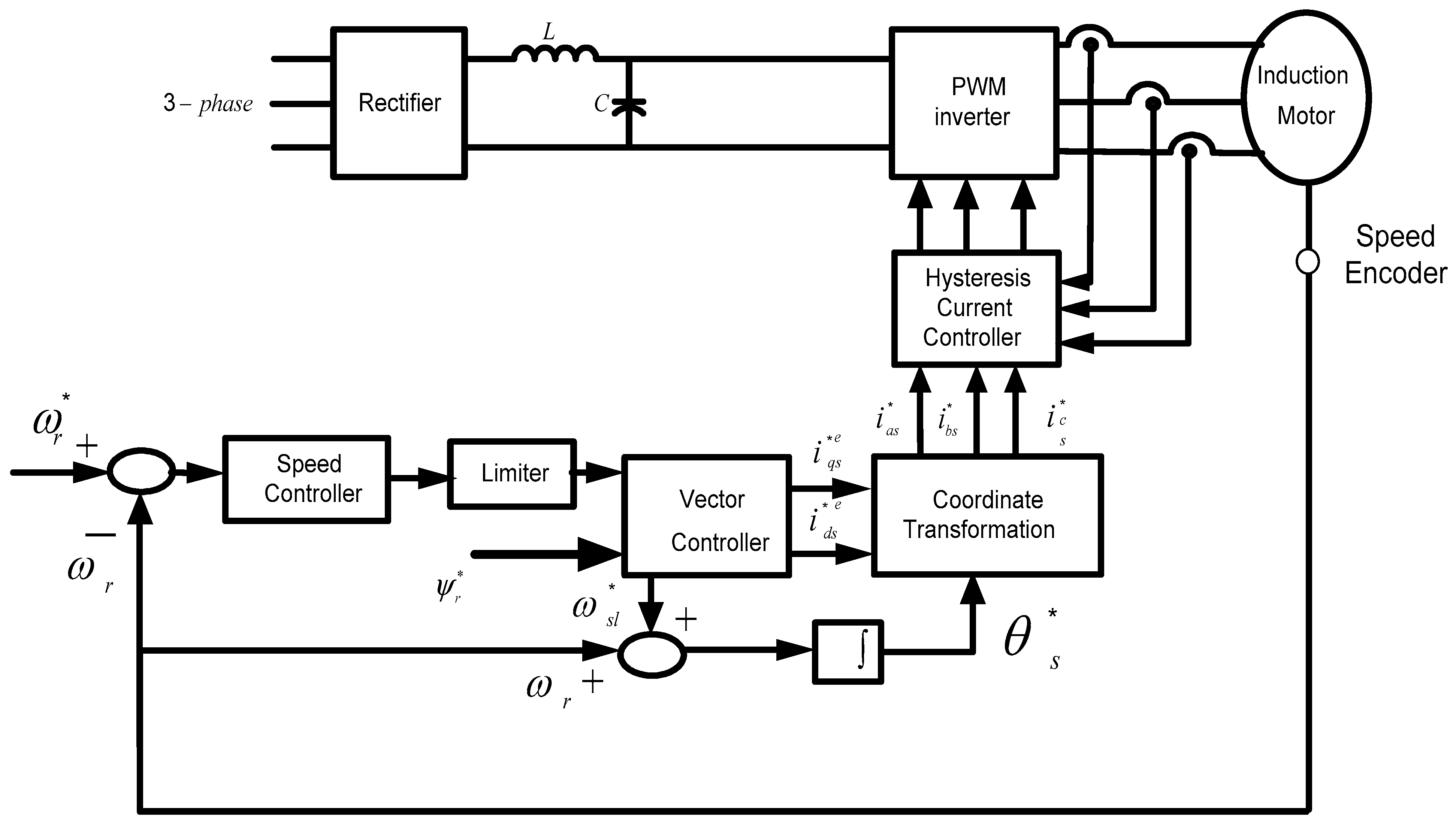
2. Mathematical Model of an Induction Motor

The induction motor can be modeled in the following mathematical differential equations represented in the rotating reference frame [8,9]:
[ v d s v q s 0 0 ] = [ R s + p L s ω s L s p L m ω s L m ω s L s R s + p L s ω s L m p L m p L m s ω s L m R r p L r s ω s L r s ω s L m p L m s ω s L r R r + p L r ] [ i d s i q s i d r i q r ]
where, p is the differential operator, d / d t , L n m is the equivalent magnetizing inductance and s represents the difference between the synchronous speed and the rotor speed and it refers to slip. The self-inductances of the motor can be represented as the following:
L n s = L n m + L l s L n r = L n m + L l r ,
where L l s and L l r are the stator and rotor leakage reactances, respectively.
The torque equation, in this case, is expressed as
T e = 3 2 P L n m L n r ( i q s ψ d r i d s ψ q r )
The previous Equation (2) is to calculate the electromagnetic torque of the motor as a function of the stator currents components, rotor flux components, pole pairs P and rotor and magnetizing inductances. Moreover, the rotor flux linkage can be written as the following equations [10]:
ψ d r = L n r i d r + L n m i d s
ψ q r = L n r i q r + L n m i q s .
The equation of motion is
J m d ω r d t + f d ω r + T l = T e
where J m is the moment of inertia, ω r is the angular speed the rotor shaft, f d is to express the damping coefficient, T e indicates the electromagnetic torque of the induction motor and T l indicates the load torque.
For achieving the finest decoupling between the d s - and q s -axis currents components, the two components of the rotor flux can be written as the following:
ψ q r = 0   and   ψ d r = ψ r
Based on operational requirements, when the rotor flux is set to a constant, the equation of the electromagnetic torque Equation (2) will be as follows:
T e = K T i q s
where
K T = 3 P 2 L n m L n r ψ r .
Equation (3) can be rewritten in the s-domain as follows:
ω r = G p ( s ) ( T e ( s ) T l ( s ) )
where
G p ( s ) = 1 / J m s + f d / J m
A block diagram representing an indirect vector-controlled induction motor drive is shown in Figure 1. The diagram consists mainly of three sub-models; a model for an induction motor under load when considering the core-loss, a hysteresis current-controlled pulse-width-modulated (PWM) inverter, and vector-control technique followed by a coordinate transformation and an outer speed-control loop.
In the vector-control scheme of Figure 1, the currents i * d s and i * q s are, respectively, the magnetizing and torque current components commands.
Where I * s = i * 2 d s + i * 2 q s , θ * t = t a n 1 ( i * q s / i * d s ) , and ω * s = ω * s l + ω r (the * refers to the command value). The stator current commands of phase “a”, which is the reference current command for the CRPWM inverter, is presented in References [3,4,5,6].
i * a s = I * s cos ( ω * s t + θ * t )
The commands for the other two stator phases are defined below. Referring to Figure 1, the slip speed command is calculated by
ω * s l = 1 T r i * q s i * d s
The torque current component command, i * q s , is obtained from the error of the speed, which applied to a speed controller provided that i * d s remains constant according to the operational requirements.
According to the above-mentioned analysis, the dynamic performance of the entire drive system, described in Figure 1, can be represented by the control system block diagram in Figure 2. This block diagram calls for accurate KT parameters and the transfer function blocks of G p ( s ) . In this paper, the speed controller K ( s ) is designed using H theory to eliminate the problems inherent to classical controllers.

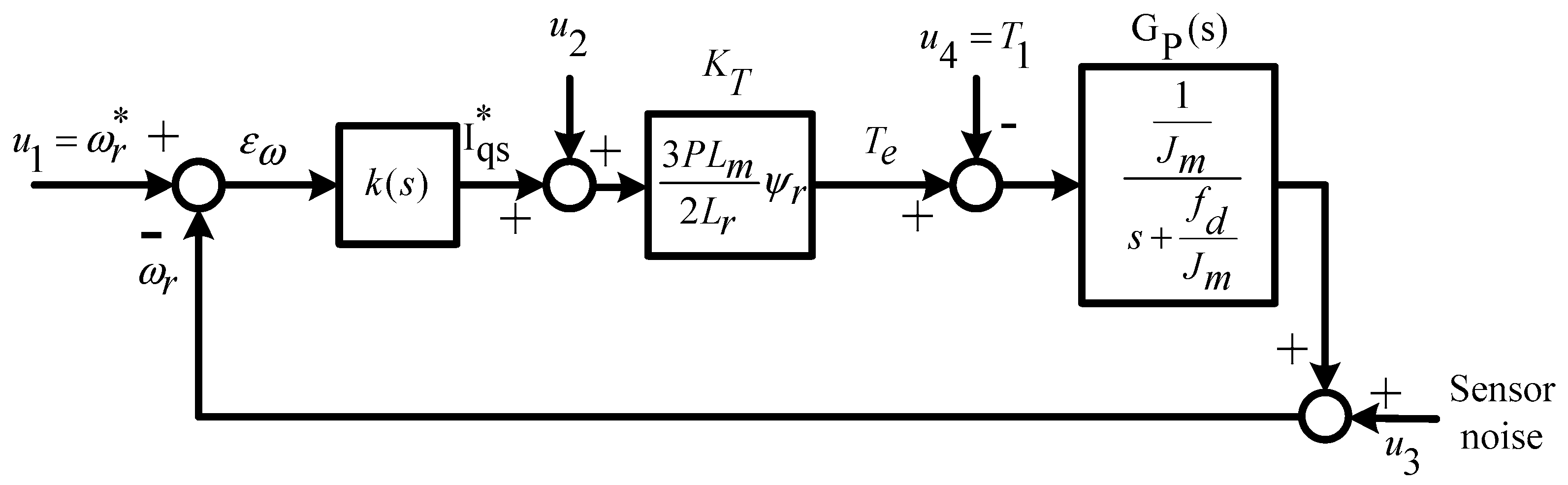
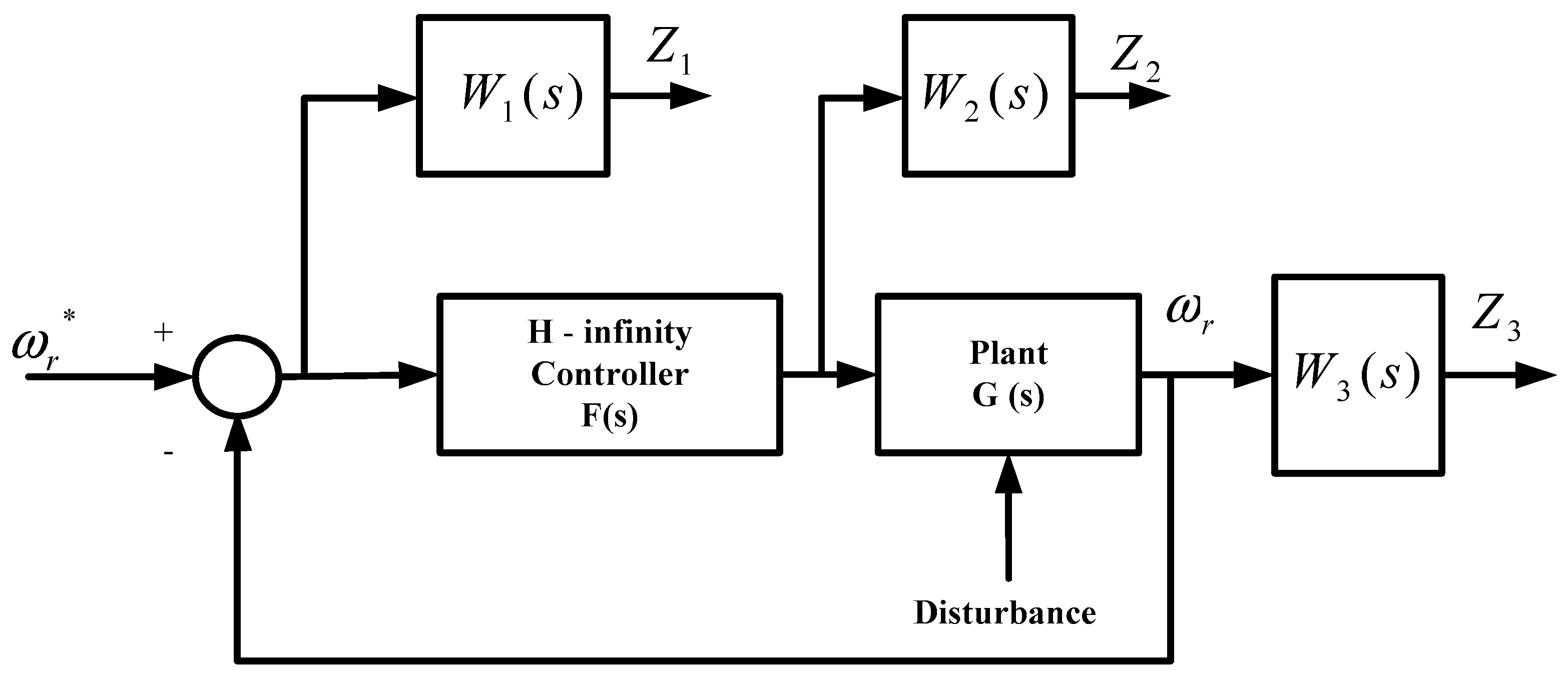
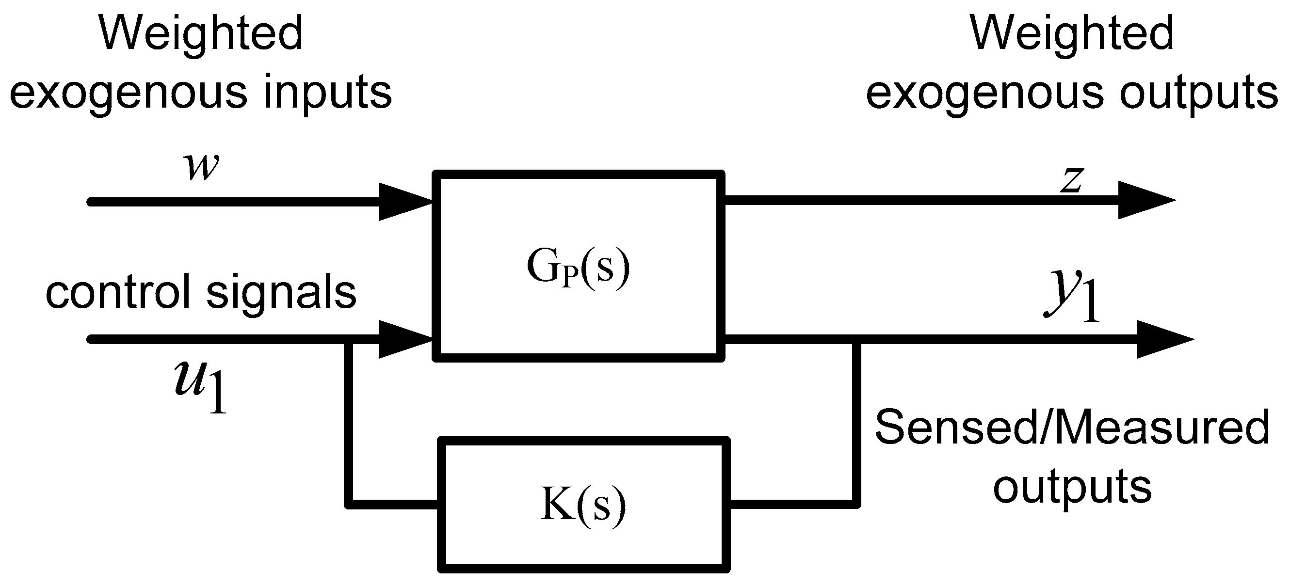
3. Design of the Proposed Controller Based on H Theory

The proposed controller is designed to achieve the following objectives:
(1)
Minimum effect of the measurement noise at high frequency
(2)
Maximum bounds on closed-loop signals to prevent saturation
(3)
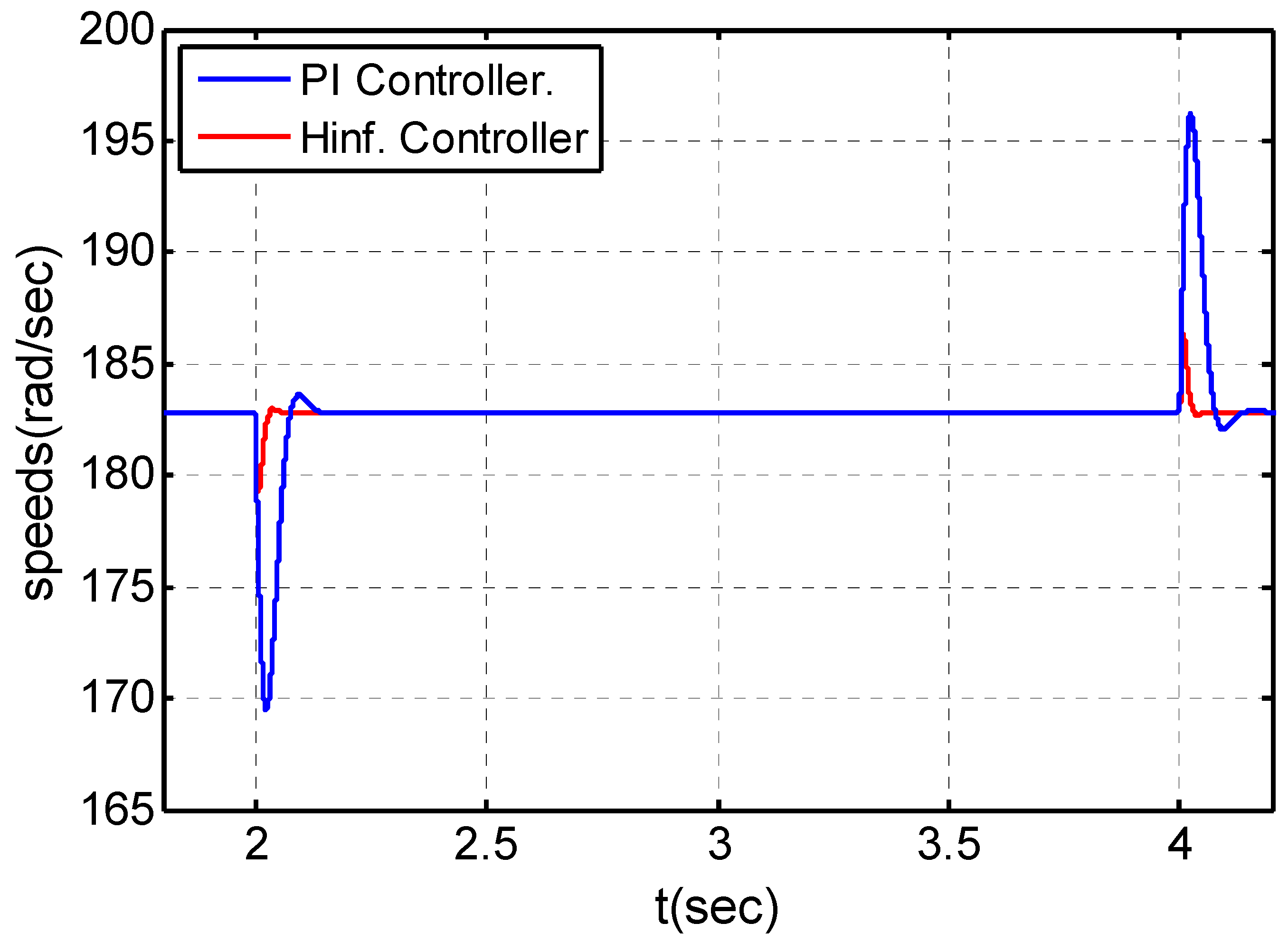
Minimum effect of load disturbance rejection, reducing the maximum speed dip
(4)
Asymptotic and good tracking for sudden changes in command signals, in addition to a rapid and excellent damping response
(5)
Survivability against system parameter variations.
The H theory offers a reliable procedure for synthesizing a controller that optimally verifies singular value loop-shaping specifications [11,12,13,14,15,16,17]. The standard setup of the H control problem consists of finding a static or dynamic feedback controller such that the H norm (a standard quantitative measure for the size of the system uncertainty) of the closed-loop transfer function below a given positive number under the constraint that the closed-loop system is internally stable.
H synthesis is performed in two stages:
  • Formulation: the first stage is to select the optimal weighting functions. The proper selections of the weighting functions give the ability to improve the robustness of the system at different operation condition and varying the model parameters. Moreover, this to reject the disturbance and noises besides the parameter uncertainties.
  • Solution: The transfer function of the weights has been updated to reach the optimal configuration. In this paper, the MATLAB optimization toolbox in the Simulink is used to determine the best weighting functions.
Figure 3 illustrates the block diagram of the H design problem, where G(s) is the transfer function of the supplemented plant (nominal plant Gp(s)) plus the weighting functions that represent the design features and objectives. u1 is the control signal and w is the exogenous input vector, which generally comprises the command signals, perturbation, disturbance, noise and measurement interference; and y1 is the controller inputs such as commands, measured output to be controlled, and measured disturbance; its components are typically tracking errors and filtered actuator signal; and z is the exogenous outputs; “error” signals to be minimized.
The objective of this problem is to design a controller K(s) for the augmented plant G(s) to have desirable characteristics for the input/output transfer based on the information of y1 (inputs to the controller k(s)) to generate the control signal u1. Therefore, the design and selection of the K(s) should counteract the influence of w and z. As a conclusion, the H design problem can be subedited as detecting an equiponderating feedback control law u1 (s) = K(s) y1(s) to neutralizes the effect of w and z and so to minimize the closed loop norm from w to z.
In the proposed control system that includes the H controller, one feedback loop is designed to adjust the speed of the motor, as given in Figure 4. The nominal system GP(s) is augmented with the weighting transfer functions W 1 ( s ) , W 2 ( s ) and W 3 ( s ) , which penalize the error signals, control signals, and output signals, respectively. The selection of the appropriate weighting functions is the quintessence of the H control. The wrong weighting function may cause the system to suffer from poor dynamic performance and instability characteristics.
Consider the augmented system shown in Figure 3. The following set of weighting transfer functions are selected to represent the required robustness and operation objectives:
A good choice for W 1 ( s ) is helpful for achieving good input reference tracking and good disturbance rejection. The matrix of the weighted error transfer function Z 1 , which is needed for regulation, can be driven as follows:
Z 1 = W 1 ( s ) ω r e f ω r .
A proper selection for the second weight W 2 ( s ) will assist in excluding actuator saturation and provide robustness to plant supplemented disturbances. The matrix of the weighted control function Z 2 can be expressed as:
Z 2 = W 2 ( s ) · u ( s ) ,
where u ( s ) is the transfer function matrix of the control signal output of the H controller.
Additionally, a proper selection for the third weight W 3 ( s ) will restrict the bandwidth of the closed loop and achieve robustness to plant output multiplicative perturbations and sensor noise attenuation at high frequencies. The weighted output variable can be provided as:
Z 3 = ω r W 3 ( s ) .
In summary, the transfer functions of interest that determine the behavior of the voltage and power closed-loop systems are:
(a) Sensitivity function: S = [I + G(s)·K(s)]−1,
where G(s) and F(s) are the transfer functions of the nominal plant and the H controller, respectively, while I is the identity matrix. Therefore, when S is minimized at low frequencies, it will secure perfect tracking and disturbance rejection.
(b) Control function: C = K(s) [I + G(s)·K(s)]−1.
Minimizing C will preclude saturation of the actuator and acquire robustness to plant additional disturbances.
(c) Complementary function: T = I − S.
Minimizing T at high frequencies will ensure robustness to plant output multiplicative perturbations and achieve noise attenuation.

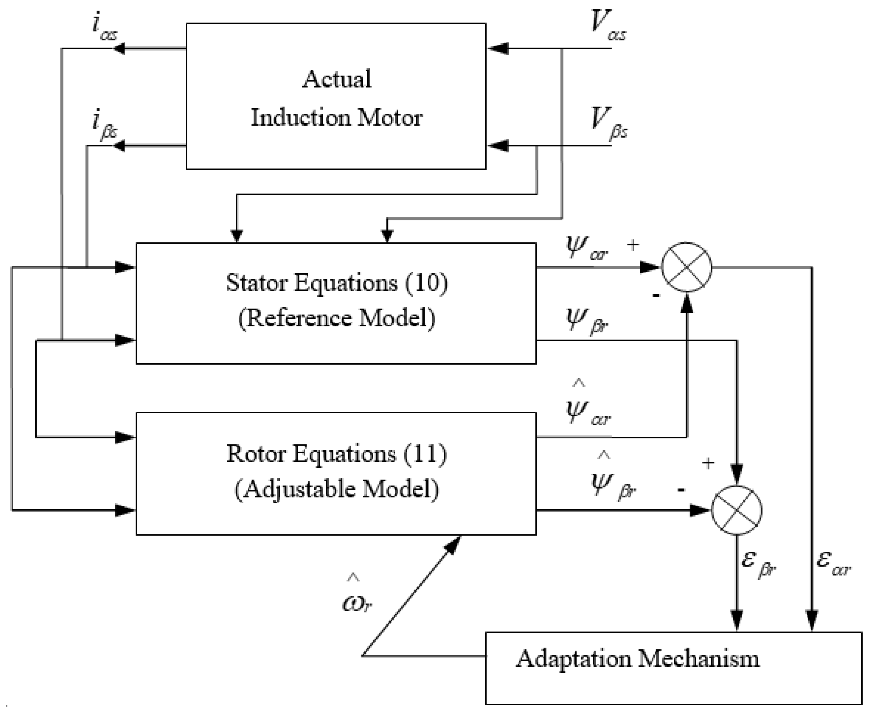
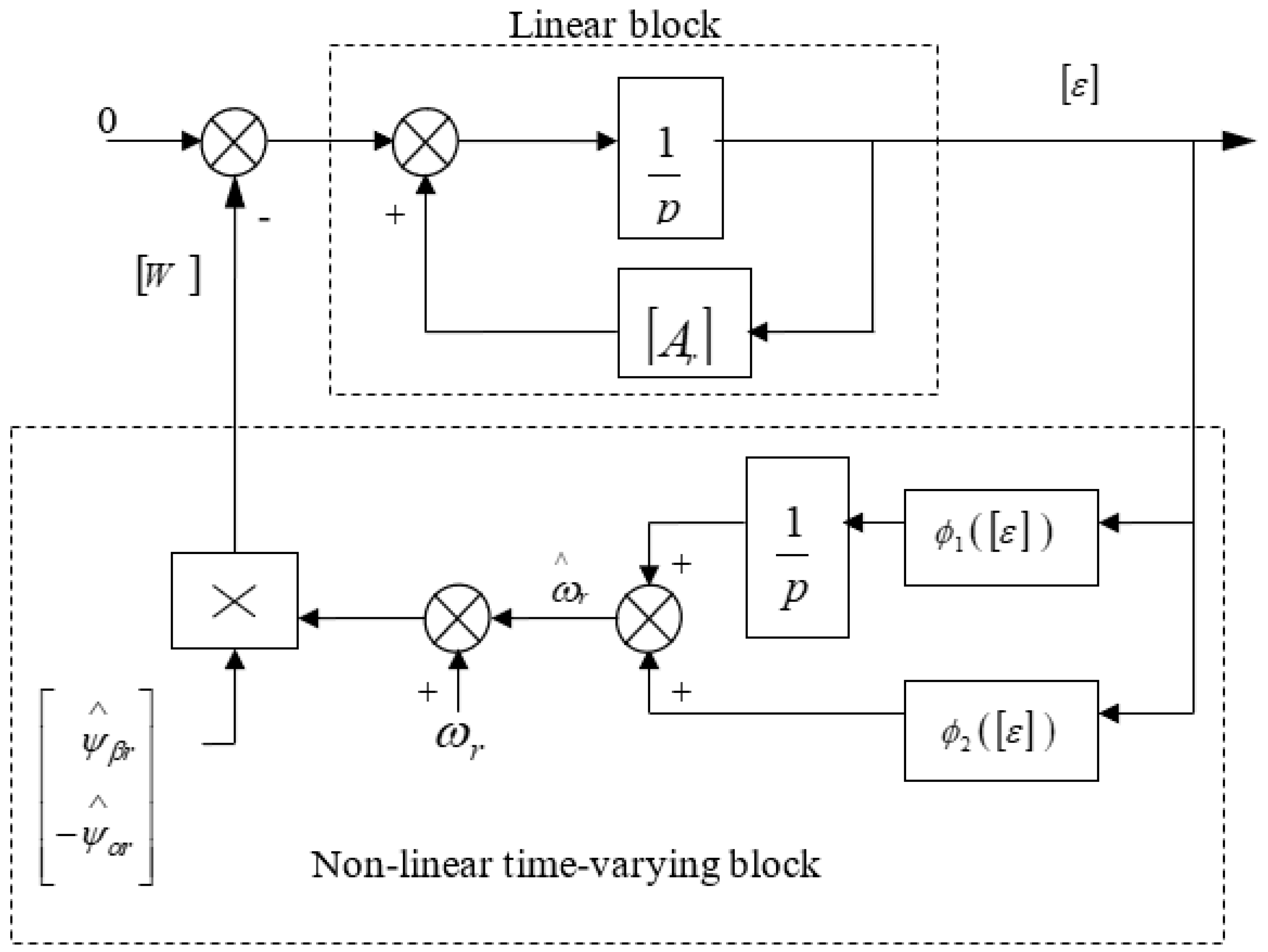
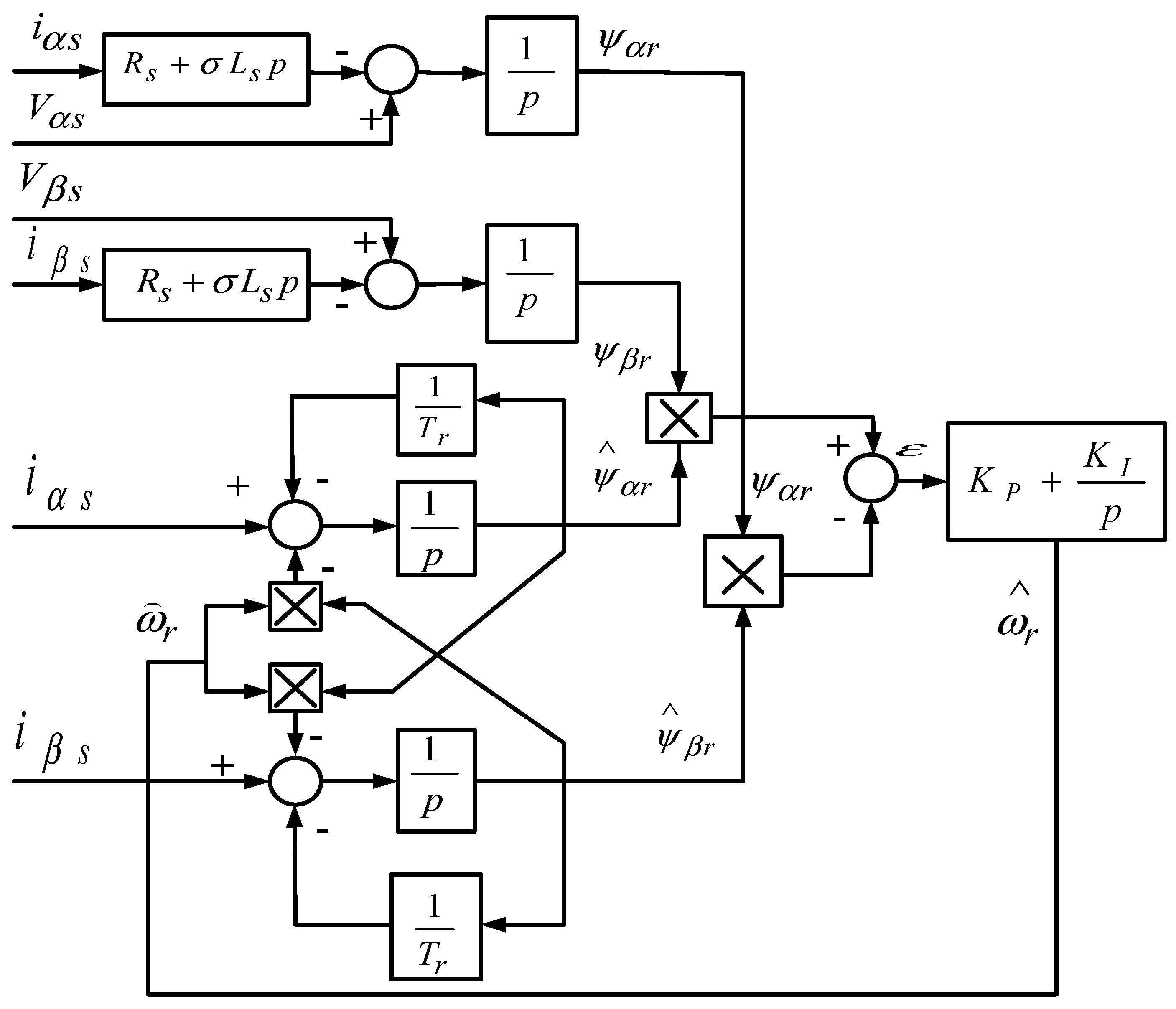
4. Robust Speed Estimation Based on MRAS Techniques for an IFO Control

The using of speed encoder in induction machines drives spoils the ruggedness and simplicity of the induction motor. Moreover, the speed sensor increases the cost of the induction motor drives. To eliminate the speed sensor, the calculation of the speed may be based on the coupled circuit equations of the motor [18,19,20,21,22,23,24,25,26,27,28,29,30,31,32,33,34]. The following explanation and analysis of the stability of the Model Reference Adaptive System (MRAS) speed estimator. In this work, the stability estimator is proven based on Popov’s criterion. The measured stator voltages and currents have been used in a stationary reference frame to describe the stator and rotor models of the induction motor. The voltage model (stator model) and the current model (rotor equation) can be written as the following in the stationary reference frame α β [18,19,20,21,22,23,24,25,26,27,28,29]:
The voltage model (stator equation):
p [ ψ α r ψ β r ] = L r L m ( [ V α s V β s ] [ ( R s + σ L s p ) 0 0 ( R s + σ L s p ) ] [ i α s i β s ] )
The current model (rotor equation):
p [ ψ α r ψ β r ] = [ ( 1 / T r ) ω r ω r ( 1 / T r ) ] [ ψ α r ψ β r ] + L m T r [ i α s i β s ]
Figure 5 illustrates an alternative way of observing the rotor speed using MRAS. Two independent rotor flux observers are constructed to estimate the components of the rotor flux vector: one based on Equation (10) and the other based on Equation (11). Because Equation (10) does not involve the quantity ω r , this observer may be regarded as a reference model of the induction motor, while Equation (11), which does involve ω r , may be regarded as an adjustable model. The states of the two models are compared and the error between them is applied to a suitable adaptation mechanism that produces the observed ω ^ r for the adjustable model until the estimated motor speed tracks well against the actual speed.
When eliciting an adaptation mechanism, it is adequate to initially act as a constant parameter of the reference model. By subtracting Equation (11) for the adjustable model from the corresponding equations belonged to the reference model Equation (10) for the rotor equations, the following equations for the state error can be obtained:
p [ ε α r ε β r ] = [ ( 1 / T r ) ω r ω r ( 1 / T r ) ] [ ε α r ε β r ] + [ ψ ^ β r ψ ^ α r ] ( ω r ω ^ r )
that is,
p [ ε ] = [ A r ] [ ε ] [ W ]
Because ω ^ r is a function of the state error, Equations (12) and (13) represent a non-linear feedback system, as shown in Figure 6.
According to Landau, hyperstability is confirmed as long as the linear time-invariant forward-path transfer matrix is precisely positive real and that the non-linear feedback (which includes the adaptation mechanism) comply with Popov’s hyperstability criterion. Popov’s criterion demands a bounded negative limit on the input/output inner product of the non-linear feedback system. Assuring this criterion leads to the following candidate adaptation mechanism [31,32,33,34]:
Let
ω ^ r = ϕ 2 ( [ ε ] ) + 0 t ϕ 1 ( [ ε ] ) d τ
then, Popov’s criterion presupposes that
0 t 1 [ ε ] T [ W ] d t γ 0 2      for   all   t 1 0
where γ 0 2 is a positive constant. Substituting for [ ε ] and [ W ] in this inequality using the definition of ω ^ r , Popov’s criterion for the system under study will be
0 t 1 { [ ε α r ψ β r ε β r ψ α r ] [ ω r ϕ 2 ( [ ε ] ) 0 t ϕ 1 ( [ ε ] ) d τ ] } d t γ 0 2
A proper solution to this inequality can be realized via the following well-known formula:
0 t 1 k ( p f ( t ) ) f ( t ) d t 1 2 k f ( 0 ) 2 ,     k 0
Using this expression, Popov’s inequality is satisfied by the following functions:
ϕ 1 = K P ( ε β r ψ ^ α r ε α r ψ ^ β r ) = K P ( ψ β r ψ ^ α r ψ α r ψ ^ β r ) .
ϕ 2 = K I ( ε β r ψ ^ α r ε α r ψ ^ β r ) = K I ( ψ β r ψ ^ α r ψ α r ψ ^ β r ) .
Figure 7 illustrates the block diagram of the MRAS. The outputs of the two models the rotor flux components. Moreover, the measured stator voltages and currents are in the stationary reference frame have been applied to be as the inputs of MRAS.

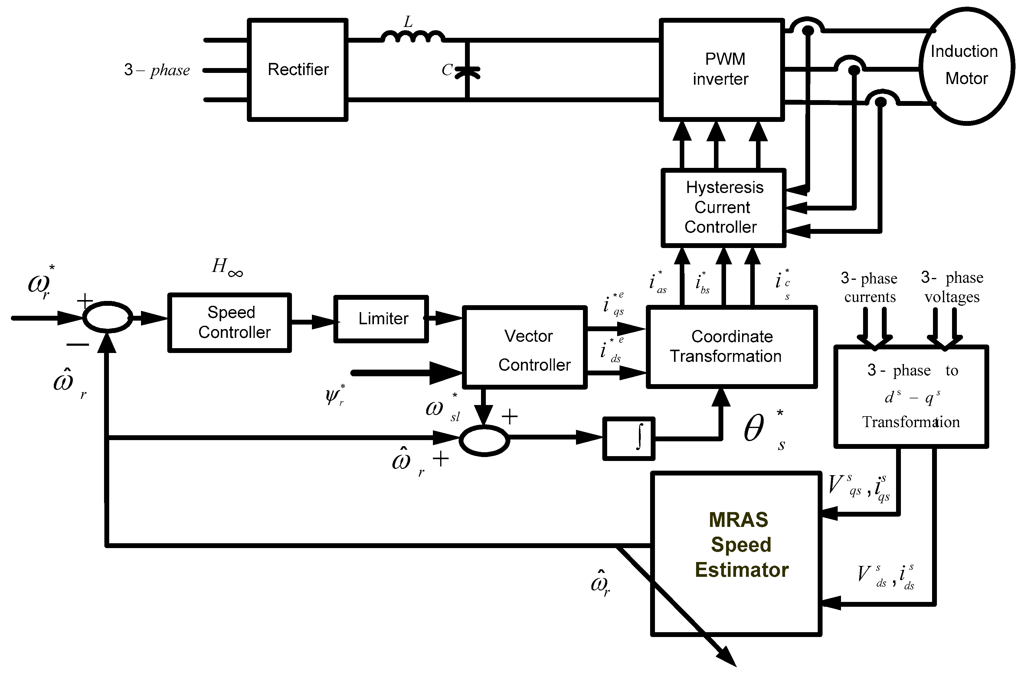
5. Proposed Sensor-Free Induction Motor Drive for High-Performance Applications

Figure 8 shows a block diagram of the proposed controller sensor-free induction motor drive system. The control system is composed of a robust controller based on H theory, hysteresis controllers, a vector rotator, a digital pulse with modulation (PWM) scheme for a transistor bridge voltage source inverter (VSI) and a motor speed estimator based on MRAS. The speed controller makes speed corrections by assessing the error between the command and estimated motor speed. The speed controller is used to generate the command q-component of the stator current i * q s . The vector rotator and phase transform in Figure 8 are used to transform the stator current components command to the three-phase stator current commands ( i * a s , i * b s and i * c s ) using the field angle position θ ^ r . The field angle is obtained by integrating the summation of the estimated speed and slip speed. The hysteresis current control compares the stator current commands to the actual currents of the machine and switches the inverter transistors in such a way as to obtain the desired command currents. Moreover, the MRAS rotor speed estimator can observe the rotor speed ω ^ r based its inputs of measured stator voltages and currents. This estimated speed is fed back to the speed controller. Additionally, the estimated speed is added to the slip speed, and the sum is integrated to obtain the field angle θ s .

6. Simulation and Experimental Results

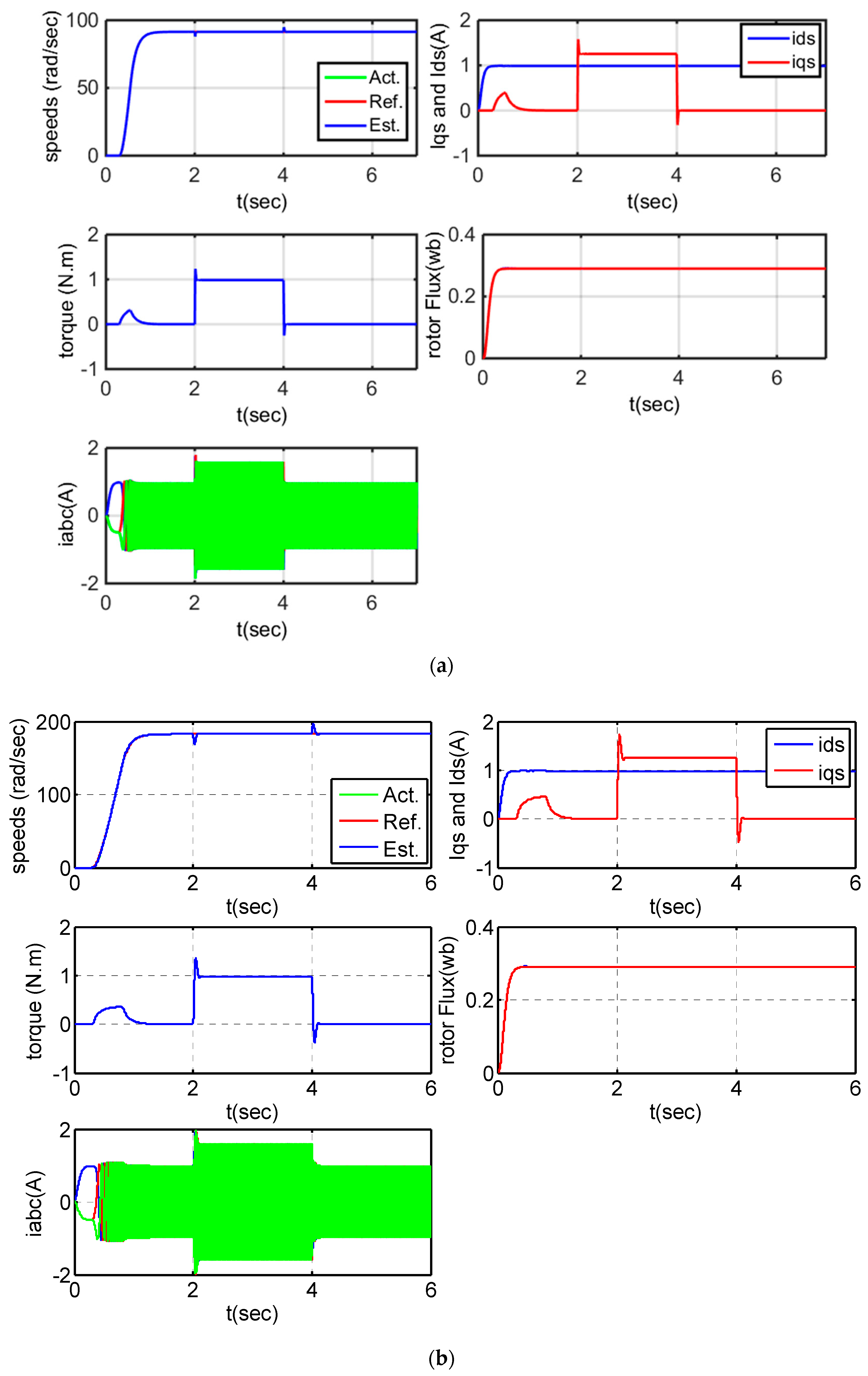
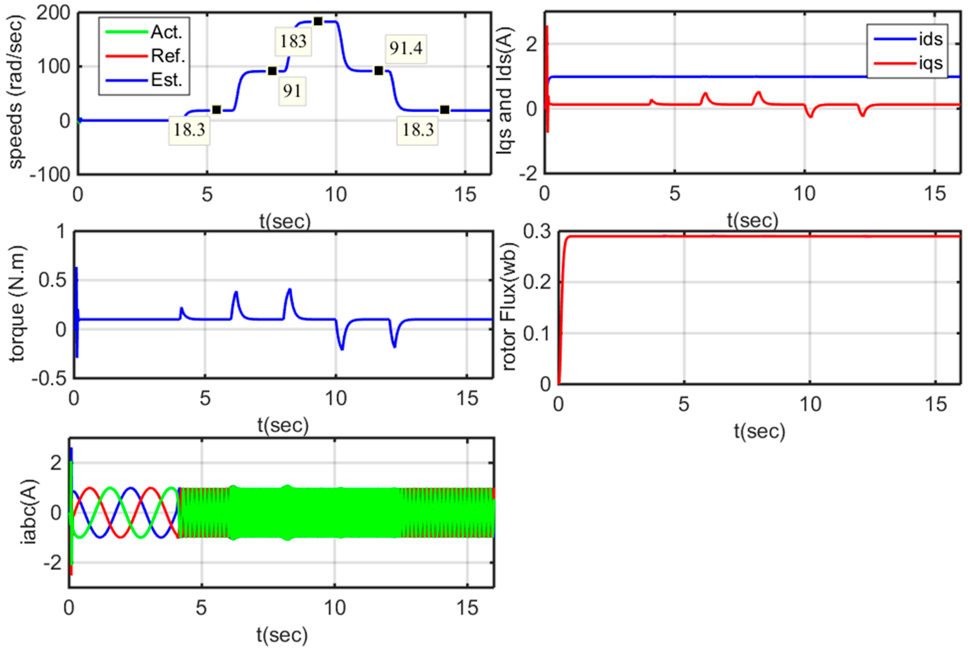
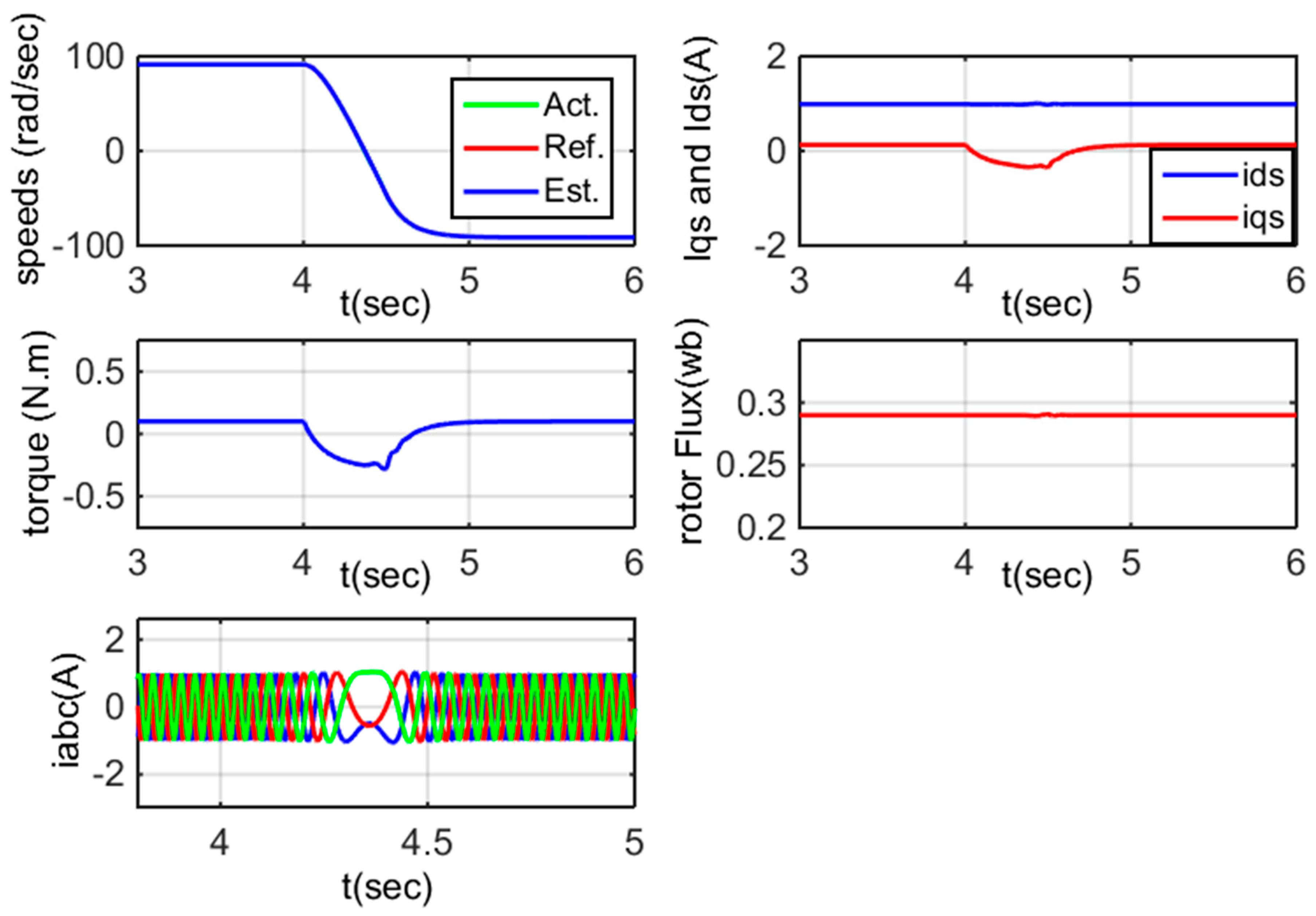
6.1. Simulation Results

The complete block diagram of the field-oriented induction motor drive with the proposed H and MRAS speed estimator has been presented in Figure 8. The proposed system has been simulated using MATLAB/Simulink under different operating conditions. The parameters and data specifications of the entire system used in the simulation are given in Table 1. The following set of weighting functions are obtained based on the application of the optimization toolbox in MATLAB/Simulink to achieve the proposed robustness and operation objectives:
W 1 = γ 1 s + 1 e 4 s + 0.001 ,   W 2 = γ 2 s + 1 e 4 s + 10 ,   W 3 = γ 3 ,
where γ 1 = 12 , γ 2 = 0.00001 , γ 3 = 0 .
The transient behavior of the proposed sensorless control system is evaluated by applying and removing the motor-rated torque (1 N.m), as shown in Figure 9. Figure 9a shows the performance of the proposed control scheme with H controller. While Figure 9b illustrates the performance of sensorless induction motor (IM) drive based on the conventional PI controller for the comparison purpose. Figure 9 shows that the motor speed can be effectively estimated and accurately tracks the actual speed when using the proposed sensorless scheme. Moreover, the figure shows that the performance of the two controllers of the PI controller and the proposed H controller have acceptable dynamic performance. Furthermore, the figure also indicates that a fast and precise transient response to motor torque is achieved with the H controller. Additionally, the stator phase current matches the value of the application and removal of the motor-rated torque.
For more validating of the H controller, Figure 10 describes the dynamic response of the control scheme based on the proposed H controller versus the PI controller when the system is subjected to a step change in the load torque. From the figure, the results show an acceptable dynamic performance of the control scheme with the PI controllers and the H against the step change in the load torque. However, the application of the H controller causes improvements in the dynamic response of the rotor speed. Clearly, the PI controller requires a long rise time compared to the H controller and the speed response has a larger overshoot with respect to the H controller. The reasons for these results of the priority of the H based induction motor drive may be because the H controller has been designed taking the weighting function for the disturbance. The discussion of these results can be more discussed as follows: The fixed parameter controllers such as PI controllers are developed at nominal operating points. However, it may not be suitable under various operating conditions. However, the real problem in the robust nonlinear feedback control system is to synthesize a control law which maintains system response and error signals to within prespecified tolerances despite the effects of uncertainty on the system. Uncertainty may take many forms but among the most significant are noise, disturbance signals, and modeling errors. Another source of uncertainty is unmodeled nonlinear distortion. Consequently, researchers have adopted a standard quantitative measure the size of the uncertainty, called the H. Therefore, the dynamic performance of the control scheme with the H controller is improved rather than the acceptable performance with the PI controller.
Figure 11 shows the actual and estimated speed transient, motor torque and stator phase current during acceleration and deceleration at different speeds. The estimated speed agreed satisfactorily with the actual speed. Additionally, a small deviation occurs from the actual speed before reaching steady-state and subsequently tracking quickly towards the command value. The motor torque response exhibits good dynamic performance. Figure 11 also shows the stator phase current during acceleration. From these simulation results, the proposed sensorless drive system is capable of operating at high speed, as illustrated in Figure 11.
In the last case of the study, the transient performance of the sensorless induction machine drive is examined by reversing the rotor speed. Figure 12 shows that induction motor drive based on the proposed robust controller has high dynamic performance at the reversing the rotor speed from 150 rad/s. Moreover, the speed estimator MRAS can accurately observe the rotor speed.

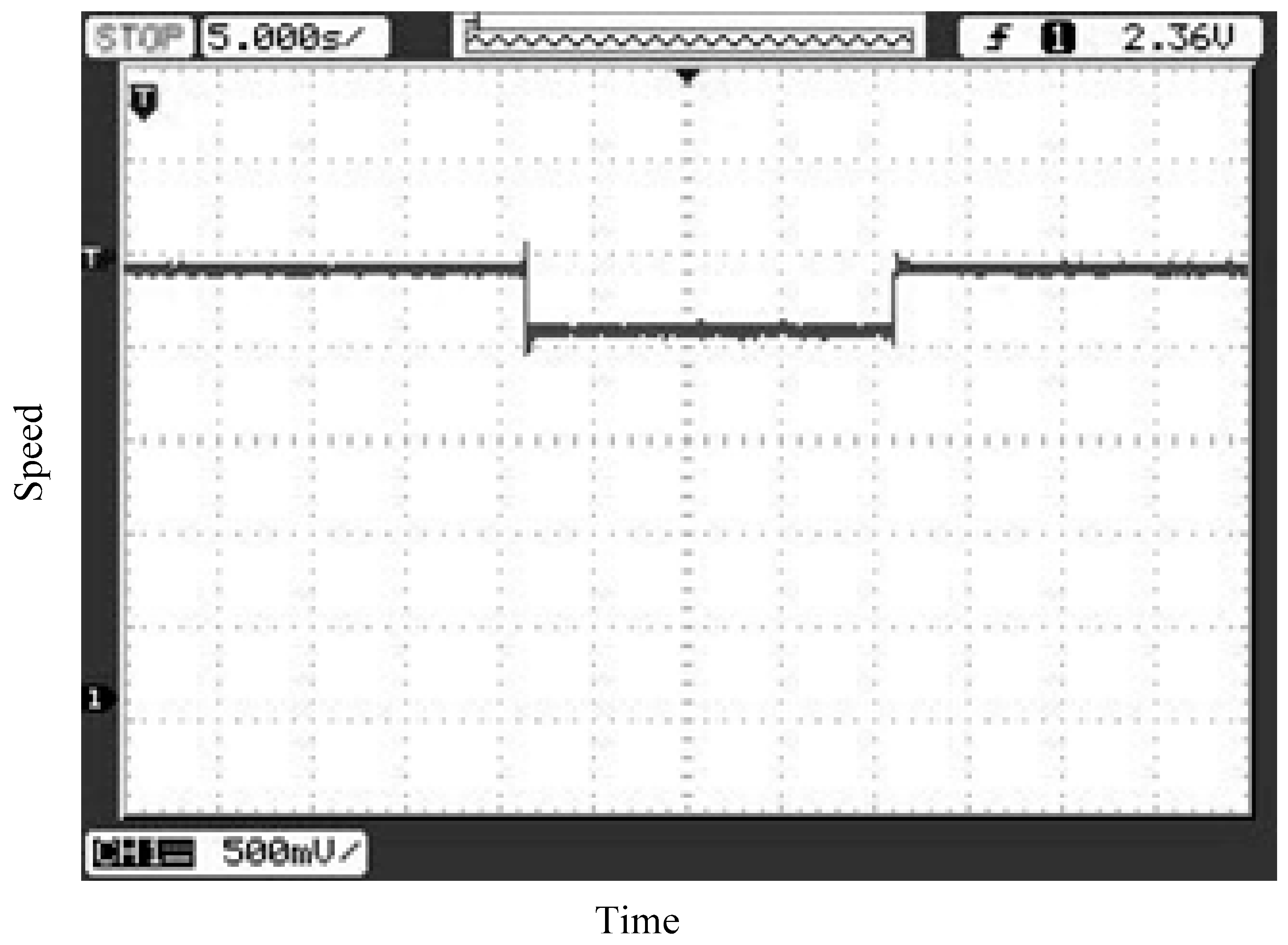
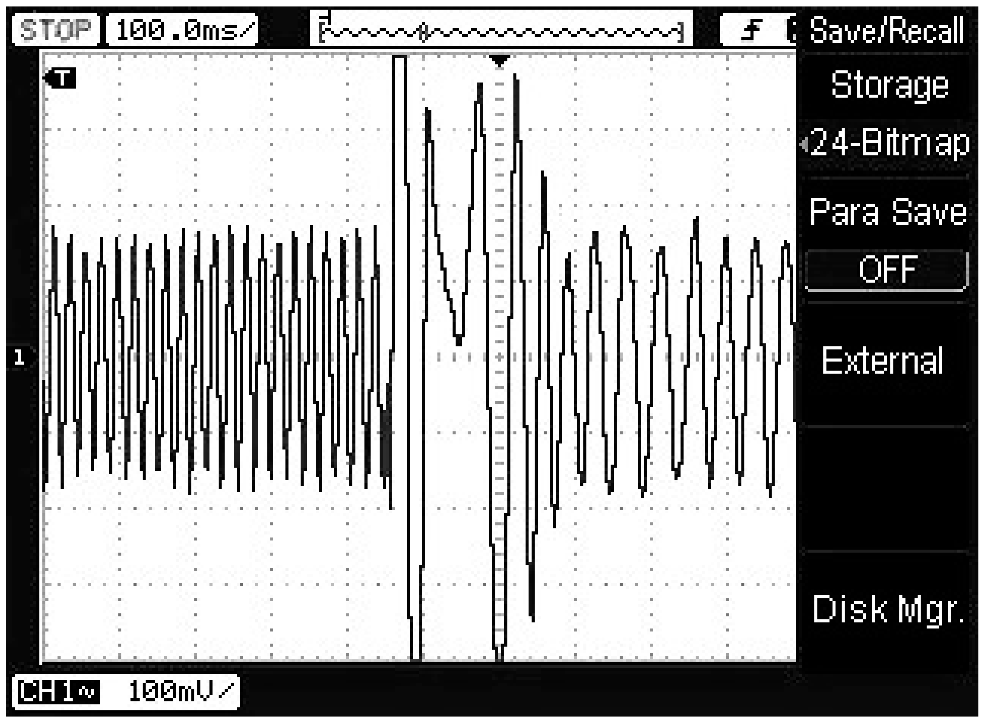
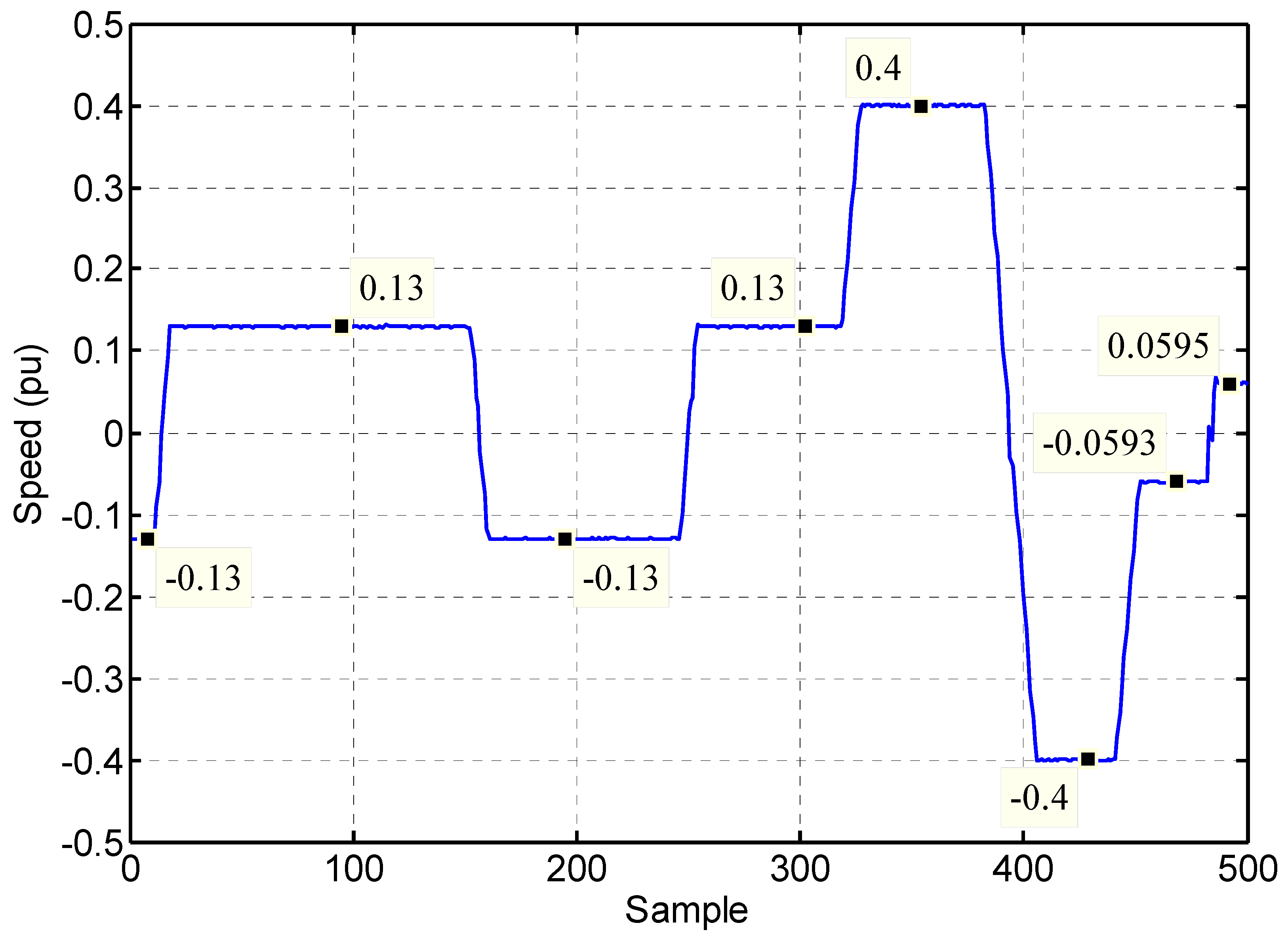
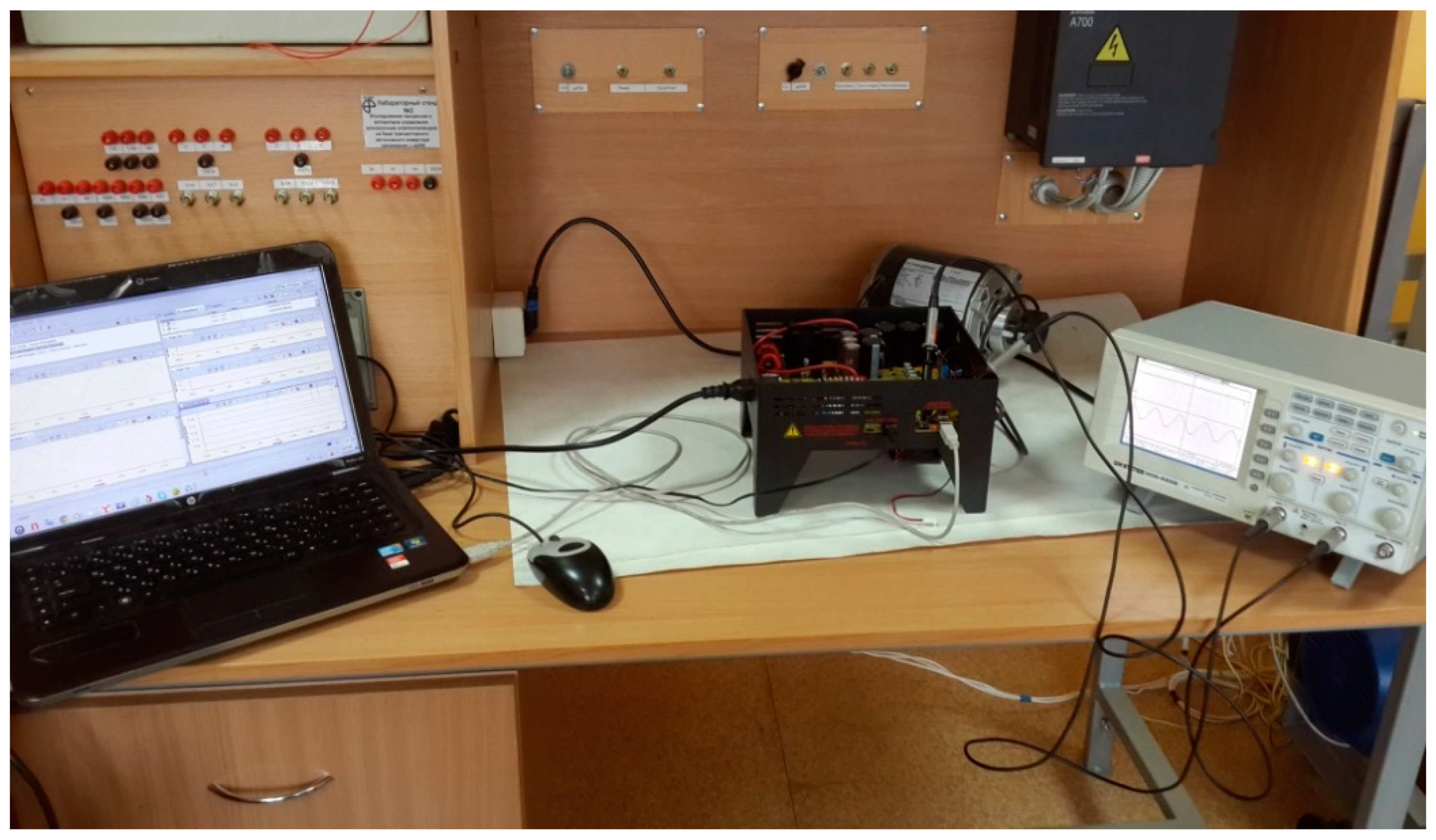
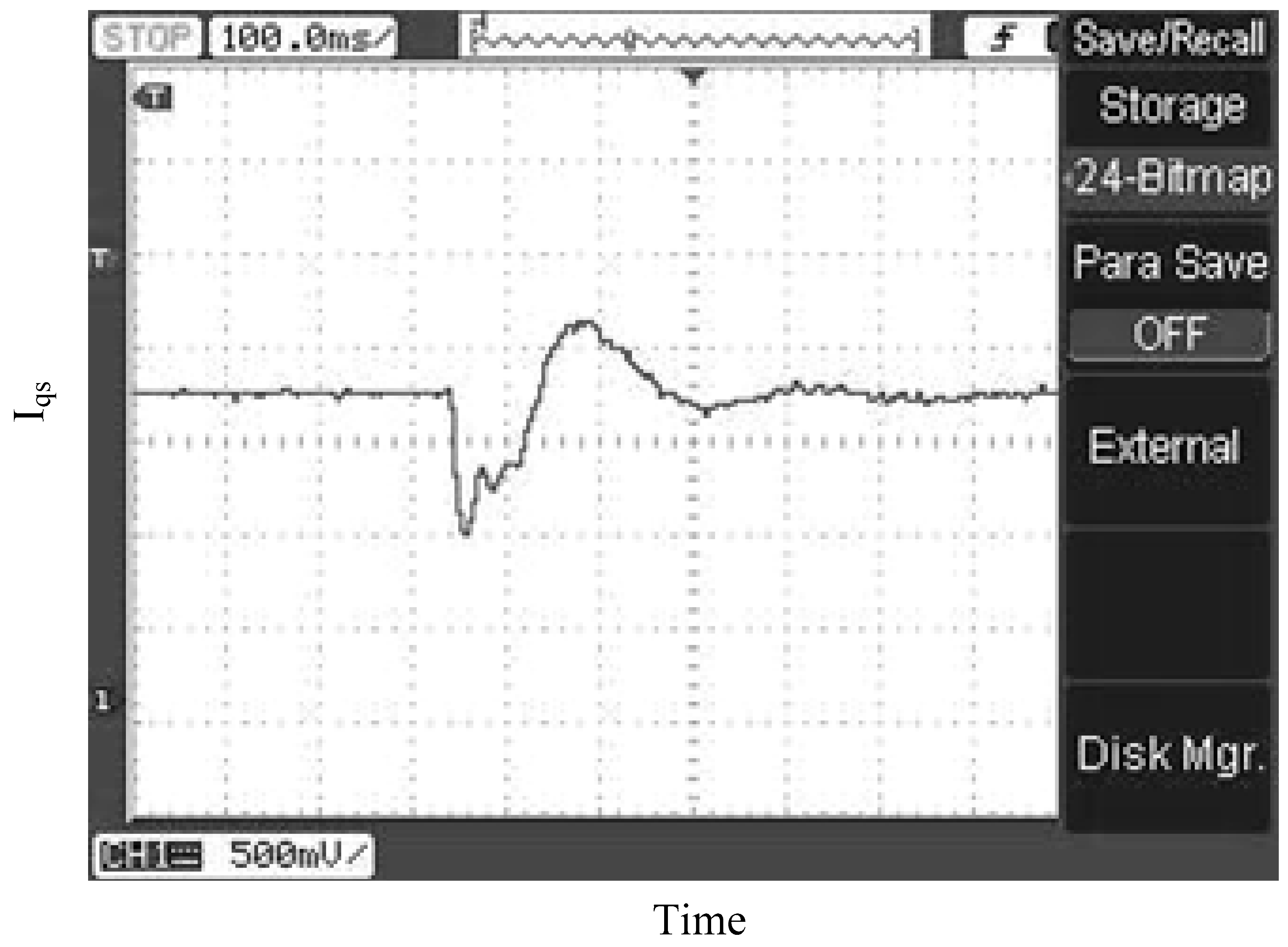
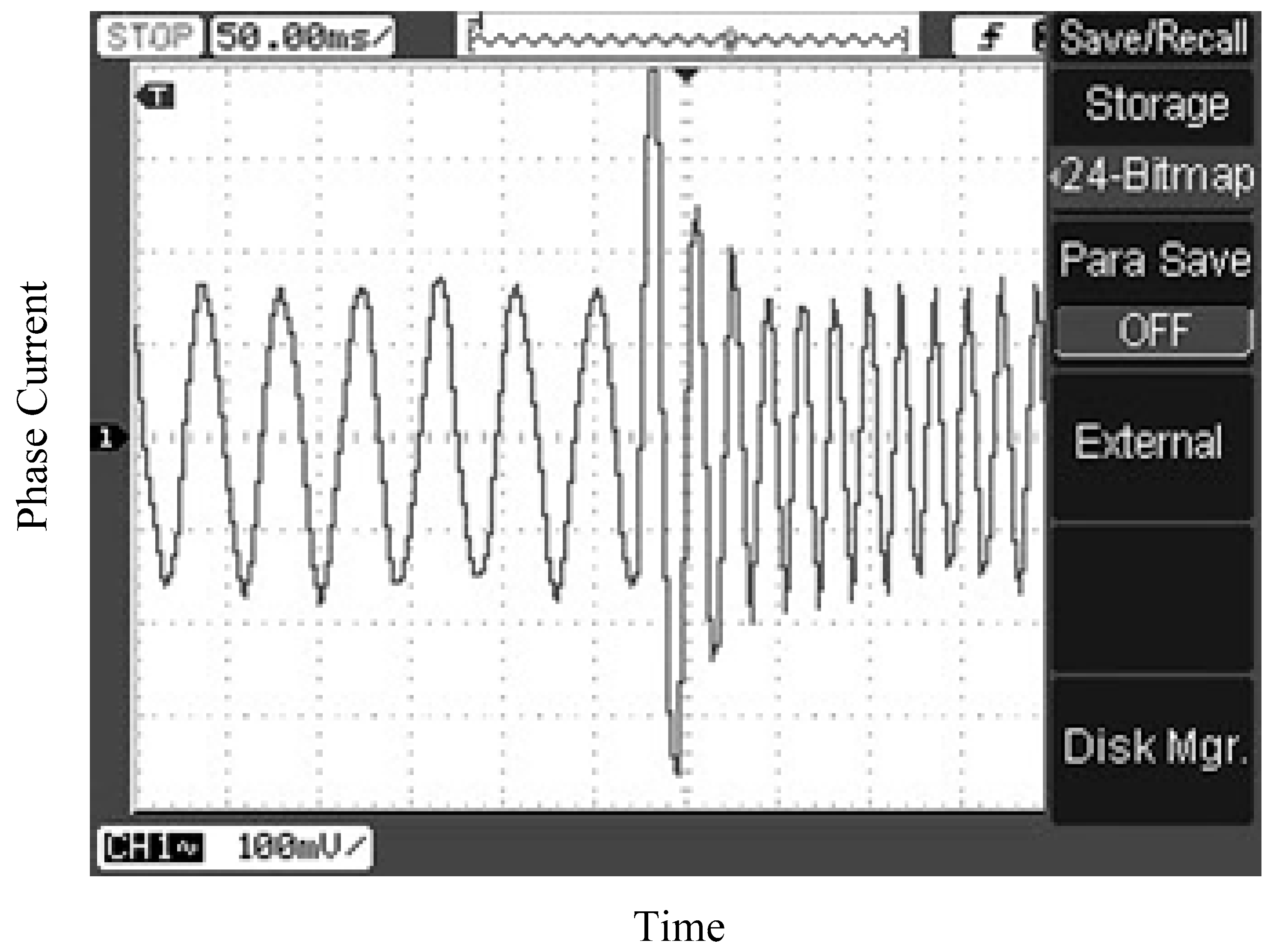
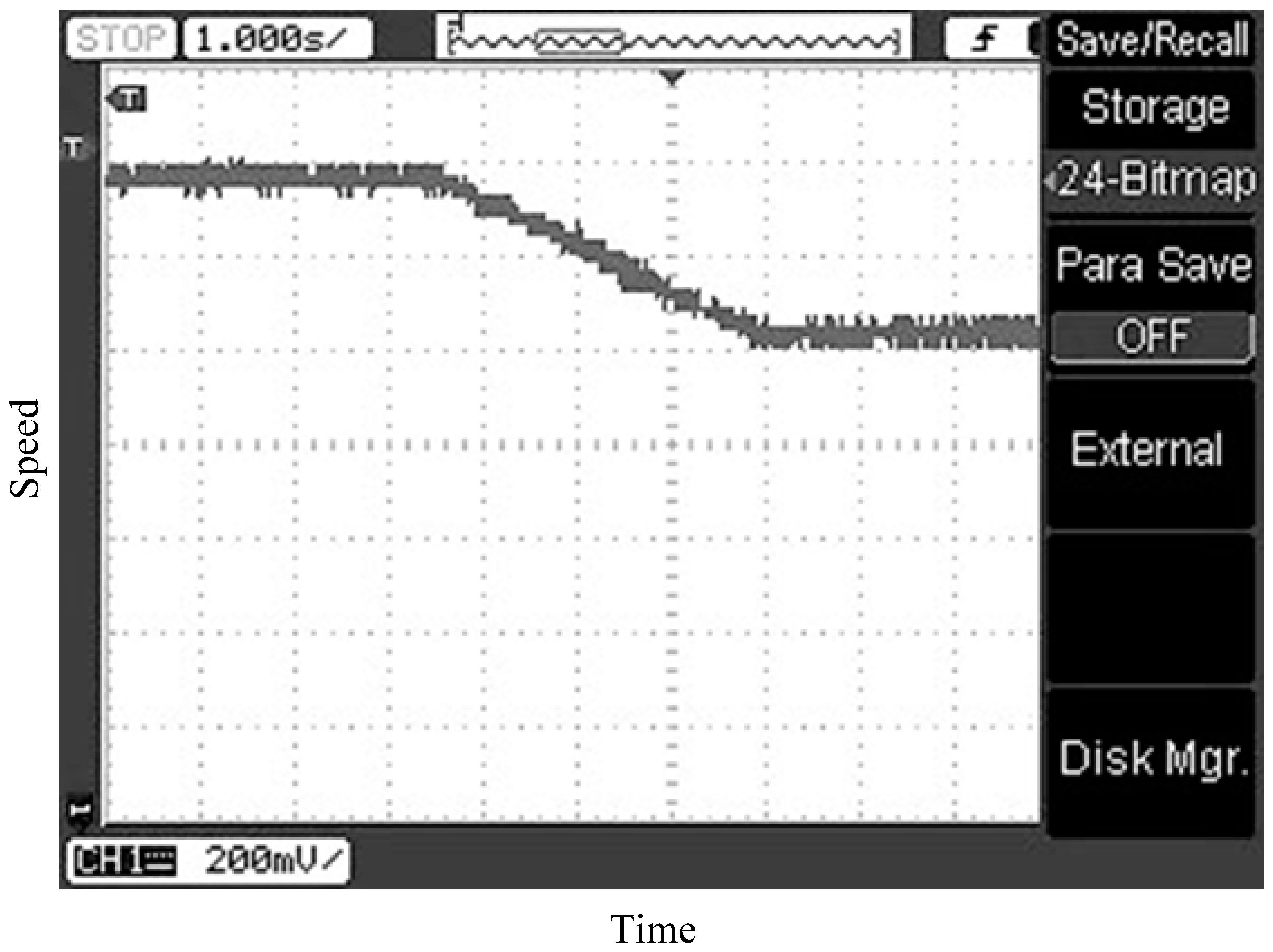
6.2. Practical Results

Figure 13 shows the experimental setup for the configured drive system. The drive system includes an induction motor; with the same parameters and data specification of the induction motor which used for simulating the proposed control scheme; linked with a digital control board (TMDSHVMTRPFCKIT from Texas Instruments with a TMS320F28035 control card) [32,35]. The complete control scheme has been programmed in the package of Code Composer Studio CCS from Texas Instruments.
To validate the effectiveness of the sensorless vector control of the induction motor drive, the experiments were accomplished at different values of the reference speed. Figure 14, Figure 15 and Figure 16 show samples of the results when the proposed system is tested at reference speeds of 0.2 pu and 0.4 pu; the base speed is assumed to be 3600 rpm (So, when the reference speed is 0.5 pu, it is mean the speed equals 1800 rpm). The results proved that the drive system effectively works at an extensive range of speeds. In addition, the actual and estimated speeds have coincided. Moreover, from Figure 16, it is obviously seen that the current of the motor is sinusoidal.
Another case of study has been tested for more evaluating of the control scheme. In this case of study, the reference speed has been reversed from 0.4 pu to 0.2 pu in the reverse direction in a ramp variation. The results of this case of study are shown in Figure 17 and Figure 18. Figure 17 shows the speed response of the control scheme. Moreover, the phase current is shown in Figure 18. The results show the control scheme has a good dynamic performance.
The last case of study has assumed many ramp changes in the references including reversing the speed. The rotor speed response is shown in Figure 19. The results have been plotted with the aid of CCS package and Digital Signal Processing (DSP). The results show the control scheme has a good dynamic performance.

7. Conclusions

In this paper, H theory has been proposed for designing an optimal robust speed controller for a field-oriented induction motor drive. The design problem of the H controller was explained and derived in standard form with an assertion on the choice of weighting functions, which fulfills the optimal robustness and performance of the drive system. The proposed control strategy has many advantages: it is robust to plant uncertainties, and has a simple implementation and a fast response. Moreover, a robust motor speed estimator based on the MRAS is presented that estimates motor speed accurately for a sensorless IFO control system. The validation of the induction motor drive was performed using both simulated and experimental implementations. The main conclusions that can be drawn from the results in this study are as follows:
(1) The effectiveness of the considered induction motor drive system with the proposed controller has been demonstrated.
(2) Compared with a PI classical controller, the response of the proposed controller shows a reduced settling time in the case of a sudden change of the speed command in addition to smaller values of the maximum speed dip and overshoot as a result of the application and removal of stepped changes in load torque.
(3) The proposed controller achieved robust performance under stepped speed change commands or changes in load torque even when the parameters of the controlled system were varied.
(4) The forward-reverse operation of the drive is obtained by the robust MRAS speed estimator and guarantees the stability of the proposed sensorless control to the system at a speed of zero. Moreover, the presented speed estimator provides an accurate speed estimation regardless of the load conditions.
(5) Both simulated and real-world experimental results demonstrate that the proposed control drive system is capable of working at a wide range of motor speeds and that it exhibits good performance in both dynamic and steady-state conditions.
Further research work should consider the nonlinearity of the induction machine parameters tacking saturation and/or iron losses into consideration. Additionally, recent optimization techniques may be applied to determine the optimal weight functions for designing the controller. Moreover, the operation range should be expanded to study and analyse the operation of the control scheme in the field weakening region. Moreover, the estimation of the machine parameters may be an interesting research point for future work for improving the overall performance of the control scheme and speed estimator.

Author Contributions

A.A.Z.D. and H.H.A. developed the idea and the simulation models. A.A.Z.D. performed the experiments and analyzed the data. A.A.Z.D., A.-H.M.E.-S. and H.H.A. wrote the paper. A.A.Z.D., A.-H.M.E.-S. and M.A.E.S. contributed by drafting and making critical revisions. All the authors organized and refined the manuscript to its present form.

Funding

This work was supported by Minia University, Egypt.

Conflicts of Interest

The authors declare no conflicts of interest.

References

  1. Vas, P. Vector Control of AC Machines; Oxford University Press: Oxford, UK, 1990; pp. 122–215. [Google Scholar]
  2. Krishnan, R.; Doran, F.C. Study of parameter Sensitivity in High Performance Inverter Fed Induction Motor Drive Systems. IEEE Trans. Ind. Appl. 1987, IA-23, 623–635. [Google Scholar] [CrossRef]
  3. Vas, P. Parameter Estimation, Condition Monitoring, and Diagnosis of Electrical Machines; Oxford Science Publications: Oxford, UK, 1993. [Google Scholar]
  4. Toliyat, H.A.; Levi, E.; Raina, M. A Review of RFO Induction Motor Parameter Estimation Techniques. IEEE Trans. Energy Convers. 2003, 18, 271–283. [Google Scholar] [CrossRef]
  5. Minami, K.; Veles-Reyes, M.; Elten, D.; Verghese, G.C.; Filbert, D. Multi-Stage Speed and Parameter Estimation for Induction Machines. In Proceedings of the Record 22nd Annual IEEE Power Electronics Specialists Conference (IEEE PESC’91), Cambridge, MA, USA, 24–27 June 1991; pp. 596–604. [Google Scholar]
  6. Roncero-Sánchez, P.L.; García-Cerrada, A.; Feliú, V. Rotor-Resistance Estimation for Induction Machines with Indirect-Field Orientation. Control Eng. Pract. 2007, 15, 1119–1133. [Google Scholar] [CrossRef]
  7. Karayaka, H.B.; Marwali, M.N.; Keyhani, A. Induction Machines Parameter Tracking from Test Data Via PWM Inverters. In Proceedings of the Record of the 1997 IEEE Industry Applications Conference Thirty-Second IAS Annual Meeting, New Orleans, LA, USA, 5–9 October 1997; pp. 227–233. [Google Scholar]
  8. Godoy, M.; Bose, B.K.; Spiegel, R.J. Design and performance evaluation of a fuzzy-logic-based variable-speed wind generation system. IEEE Trans. Energy Convers. 1997, 33, 956–964. [Google Scholar]
  9. Munteau, I.; Cutululis, N.A.; Bratcu, A.I.; Ceanga, E. Optimization of variable speed wind power systems based on a LQG approach. In Proceedings of the IFAC Workshop on Control Applications of Optimisation—CAO’03 Visegrad, Visegrad, Hungary, 30 June–2 July 2003. [Google Scholar]
  10. Hassan, A.A.; Mohamed, Y.S.; Yousef, A.M.; Kassem, A.M. Robust control of a wind driven induction generator connected to the utility grid. Bull. Fac. Eng. Assiut Univ. 2006, 34, 107–121. [Google Scholar]
  11. Attaiaence, C.; Perfetto, A.; Tomasso, G. Robust postion control of DC drives by means of H controllers. Proc. IEE Electr. Power Appl. 1999, 146, 391–396. [Google Scholar] [CrossRef]
  12. Naim, R.; Weiss, G.; Ben-Yakakov, S. H control applied to boost power converters. IEEE Trans. Power Electron. 1997, 12, 677–683. [Google Scholar] [CrossRef]
  13. Lin, F.-J.; Lee, T.; Lin, C. Robust H controller design with recurrent neural network for linear synchronous motor drive. IEEE Trans. Ind. Electron. 2003, 50, 456–470. [Google Scholar]
  14. Pohl, L.; Vesely, I. Speed Control of Induction Motor Using H Linear Parameter Varying Controller. IFAC-PapersOnLine 2016, 49, 74–79. [Google Scholar] [CrossRef]
  15. Kao, Y.-T.; Liu, C.-H. Analysis and design of microprocessor-based vector-controlled induction motor drives. IEEE Trans. Ind. Electron. 1992, 39, 46–54. [Google Scholar] [CrossRef]
  16. Prempain, E.; Postlethwaite, I.; Benchaib, A. A linear parameter variant H control design for an induction motor. Control Eng. Pract. 2002, 10, 633–644. [Google Scholar] [CrossRef]
  17. Rigatos, G.; Siano, P.; Wira, P.; Profumo, F. Nonlinear H-infinity feedback control for asynchronous motors of electric trains. Intell. Ind. Syst. 2015, 1, 85–98. [Google Scholar] [CrossRef]
  18. Riberiro, L.A.D.; Lima, A.M.N. Parameter Estimation of Induction Machines Under Sinusoidal PWM Excitation. IEEE Trans. Energy Convers. 1999, 14, 1218–1223. [Google Scholar] [CrossRef]
  19. Moonl, S.; Keyhani, A. Estimation of Induction Machines Parameters from Standstill Time-Domain Data. IEEE Trans. Ind. Appl. 1994, 30, 1609–1615. [Google Scholar] [CrossRef]
  20. Lima, A.M.N.; Jacobina, C.B.; Filho, E.B.D. Nonlinear Parameter Estimation of Steady-state Induction Machine Models. IEEE Trans. Ind. Electron. 1997, 44, 390–397. [Google Scholar] [CrossRef]
  21. Yang, G.; Chin, T.H. Adaptive-Speed Identification Scheme for a Vector-Controlled Speed Sensorless Inverter-Induction Motor Drive. IEEE Trans. Ind. Appl. 1993, 29, 820–825. [Google Scholar] [CrossRef]
  22. Kubota, H.; Matsuse, K. Speed Sensorless Field-Oriented Control of Induction Motor with Rotor Resistance Adaptation. IEEE Trans. Ind. Appl. 1994, 30, 1219–1224. [Google Scholar] [CrossRef]
  23. Suwankawin, S.; Sangwongwanich, S. Design Strategy of an Adaptive Full Order Observer for Speed Sensorless Induction Motor Drives Tracking Performance and Stabilization. IEEE Trans. Ind. Electron. 2006, 53, 96–119. [Google Scholar] [CrossRef]
  24. Al-Tayie, J.; Acarnley, P. Estimation of Speed, Stator Temperature and Rotor Temperature in Cage Induction Motor Drive Using the Extended Kalman Filter Algorithm. Proc. IEE Electr. Power Appl. 1997, 144, 301–309. [Google Scholar] [CrossRef]
  25. Barut, M.; Bogosyan, O.S.; Gokasan, M. Switching EKF Technique for Rotor and Stator Resistance Estimation in Speed Sensorless Control of Induction Motors. Energy Convers. Manag. 2007, 48, 3120–3134. [Google Scholar] [CrossRef]
  26. Jingchuan, L.; Longya, X.; Zhang, Z. An Adaptive Sliding-Mode Observer for Induction Motor sensorless Speed Control. IEEE Trans. Ind. Appl. 2005, 41, 1039–1046. [Google Scholar]
  27. Rashed, M.; Stronach, A.F. A Stable Back-EMF MRAS-Based Sensorless Low Speed Induction Motor Drive Insensitive to Stator Resistance Variation. IEE Proc. Electr. Power Appl. 2004, 151, 685–693. [Google Scholar] [CrossRef]
  28. Mohamed, Y.S.; El-Sawy, A.M.; Zaki, A.A. Rotor Resistance Identification for Speed Sensorless Vector Controlled Induction Motor Drives Taking Saturation Into Account. J. Eng. Sci. Assiut Univ. 2009, 37, 393–412. [Google Scholar]
  29. Middeton, R.H.; Goodwin, G.C. Digital Control and Estimation, 1st ed.; Prentice-Hall, Inc.: Englewood Cliffs, NJ, USA, 1990; Volume 1. [Google Scholar]
  30. Blasco-Gimenez, R.; Asher, G.; Summer, M.; Bradley, K. Dynamic Performance Limitations for MRAS Based Sensorless Induction Motor Drives. Part 1: Stability Analysis for the Closed Loop Drive. Proc. IEE-Electr. Power Appl. 1996, 143, 113–122. [Google Scholar] [CrossRef]
  31. Diab, A.A.; Khaled, A.; Elwany, M.A.; Hassaneen, B.M. Parallel estimation of rotor resistance and speed for sensorless vector controlled induction motor drive. In Proceedings of the 2016 17th International Conference of Young Specialists on Micro/Nanotechnologies and Electron Devices (EDM), Erlagol, Russia, 30 June–4 July 2016. [Google Scholar]
  32. Diab, A.A. Real-Time Implementation of Full-Order Observer for Speed Sensorless Vector Control of Induction Motor Drive. J. Control Autom. Electr. Syst. 2014, 25, 639–648. [Google Scholar] [CrossRef]
  33. Diab, A.A.Z. Implementation of a novel full-order observer for speed sensorless vector control of induction motor drives. Electr. Eng. 2016, 99, 907–921. [Google Scholar] [CrossRef]
  34. Diab, A.A.Z. Novel robust simultaneous estimation of stator and rotor resistances and rotor speed to improve induction motor efficiency. Int. J. Power Electron. 2017, 8, 267–287. [Google Scholar] [CrossRef]
  35. Texas Instruments C2000 Systems and Applications Team. High Voltage Motor Control and PFC (R1.1) Kit Hardware Reference Guide, v. 2. 2012. Available online: http://www.ti.com/tool/TMDSHVMTRPFCKIT (accessed on 31 January 2019).
Figure 1. Block diagram of an indirect field-oriented (IFO)-controlled induction motor drive.
Energies 12 00961 g001
Figure 2. Block diagram of the speed-control system of an IFO-controlled induction motor drive.
Energies 12 00961 g002
Figure 3. General setup of the H design problem.
Energies 12 00961 g003
Figure 4. Simplified block diagram of the augmented plant, including the H controller.
Energies 12 00961 g004
Figure 5. Structure of the MRAS system for motor speed estimation.
Energies 12 00961 g005
Figure 6. Representation of MRAS as a non-linear feedback system.
Energies 12 00961 g006
Figure 7. Block diagram of the Model Reference Adaptive System (MRAS) speed estimation system.
Energies 12 00961 g007
Figure 8. The block diagram of the proposed sensorless induction motor drive based on H theory.
Energies 12 00961 g008
Figure 9. Simulation results of speed transient with load step changes of rated values using the proposed sensorless drive system; (a) with H controller and (b) with PI controller.
Energies 12 00961 g009
Figure 10. Response of the H controller versus the PI controller.
Energies 12 00961 g010
Figure 11. Simulation results of the acceleration and deceleration operation using the proposed sensorless drive system.
Energies 12 00961 g011
Figure 12. System performance when reversing the motor speed.
Energies 12 00961 g012
Figure 13. A photo of the experimental setup for induction motor drive.
Energies 12 00961 g013
Figure 14. The transient performance of the entire drive system under variable speed from 0.4 pu to 0.2 pu to 0.4 pu.
Energies 12 00961 g014
Figure 15. The transient performance of IqS of the entire drive system under variable speed from 0.4 pu to 0.2 pu.
Energies 12 00961 g015
Figure 16. Current of phase (a) at reference speeds of 0.2 pu to 0.4 pu.
Energies 12 00961 g016
Figure 17. The transient performance of IqS of the entire drive system under variable speed from 0.4 pu to 0.2 pu.
Energies 12 00961 g017
Figure 18. Current of phase (a) for the case of speed reversing from 0.4 pu to 0.2 pu.
Energies 12 00961 g018
Figure 19. The transient performance of multi-variation in the rotor speed with reversing (The experimental data and measurements have been collected with the aid of the DSP and plotted using Matlab plot tool).
Energies 12 00961 g019
Table 1. Parameters and data specifications of the induction motor.
Rated Power (W)180Rated Voltage (V)220
Rated current (A)1.3–1.4Rated frequency (Hz)60
Rs (Ω)11.29Rr (Ω)6.11
Ls (H)0.021Lr (H)0.021
Lm (H)0.29Rated rotor flux, (wb)0.3
J (kg.m2)0.00940Rated speed (rpm)1750

