Power Management Control Strategy Based on Artificial Neural Networks for Standalone PV Applications with a Hybrid Energy Storage System


Abstract
1. Introduction
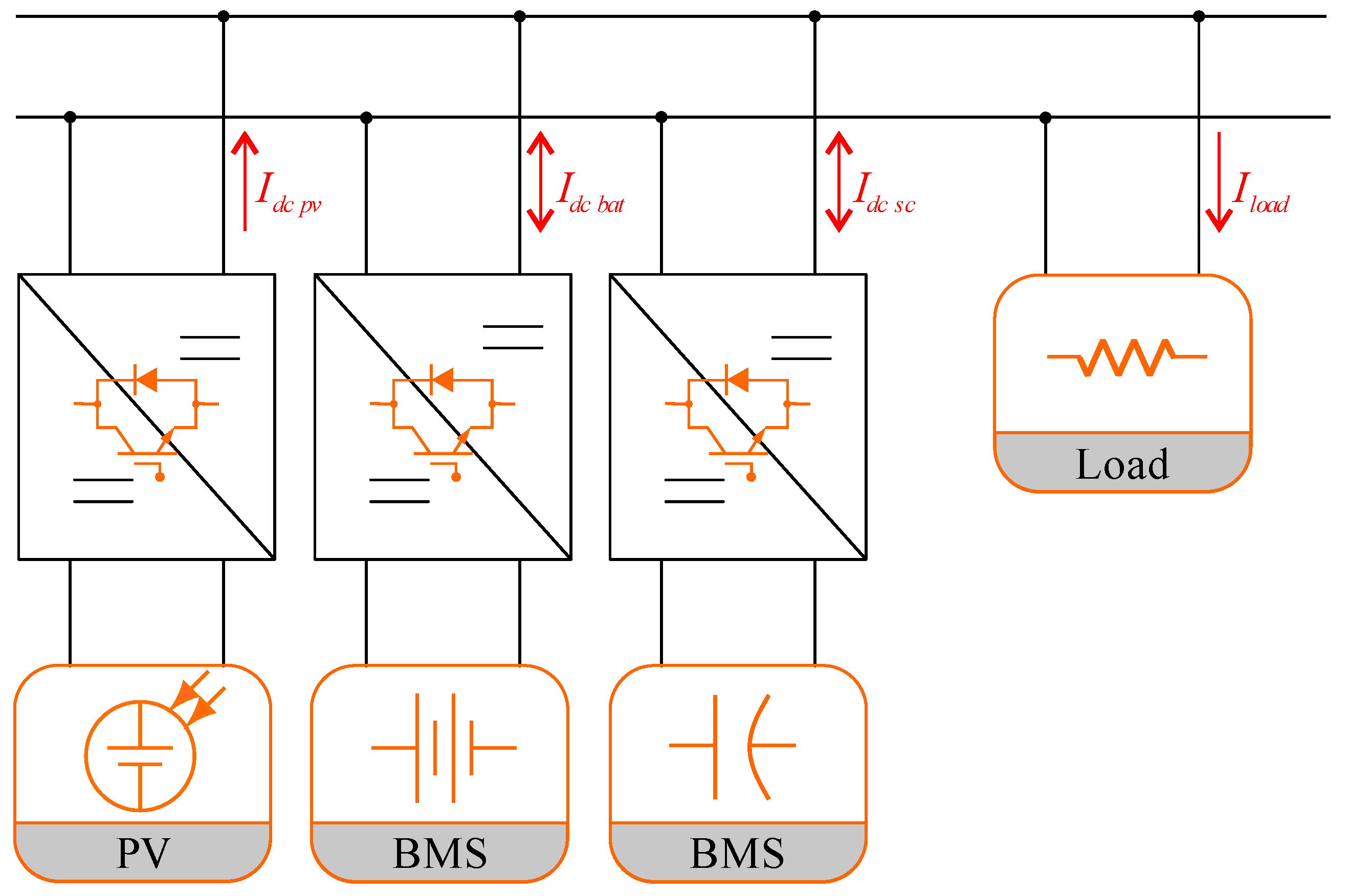
2. Proposed System Structure
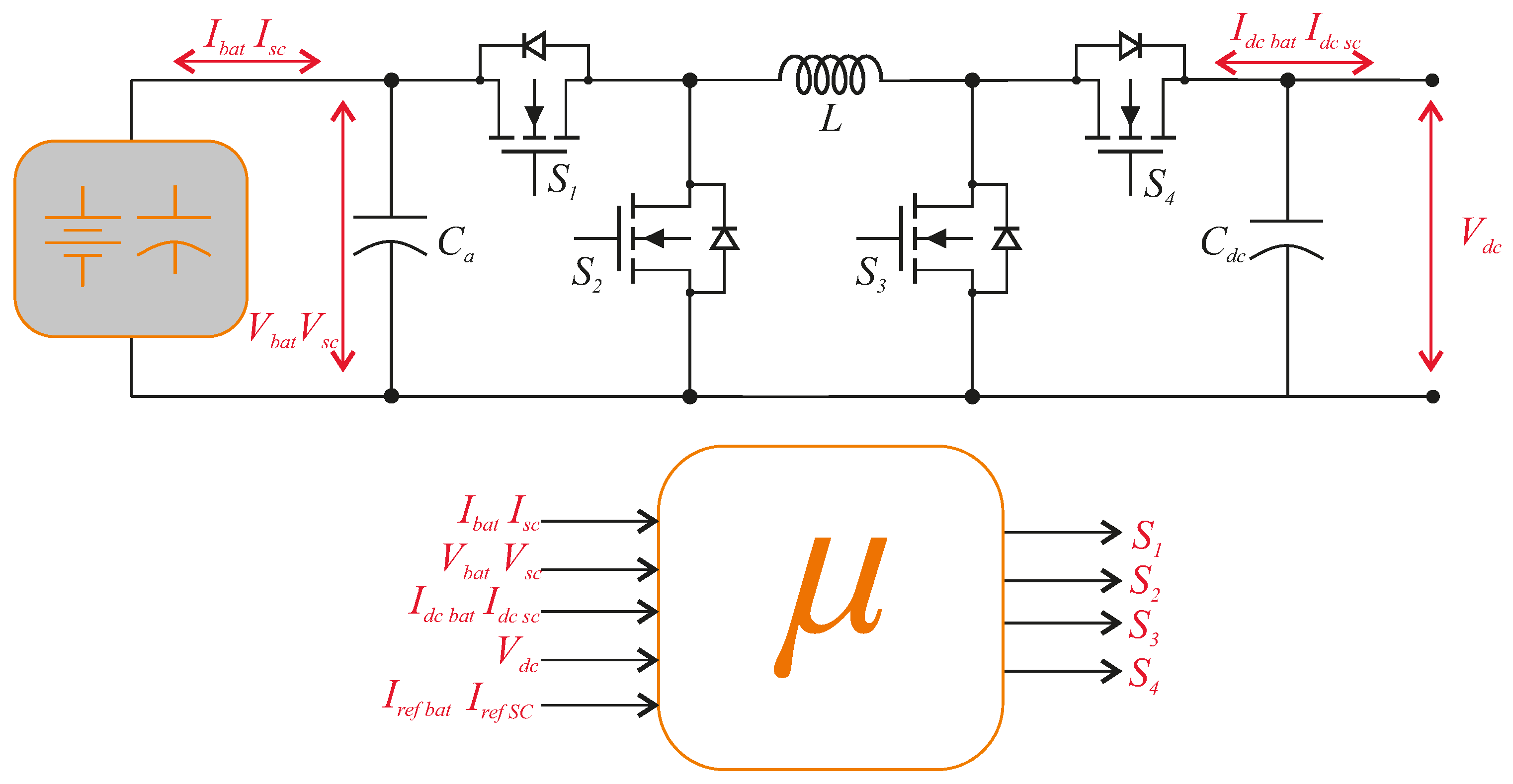
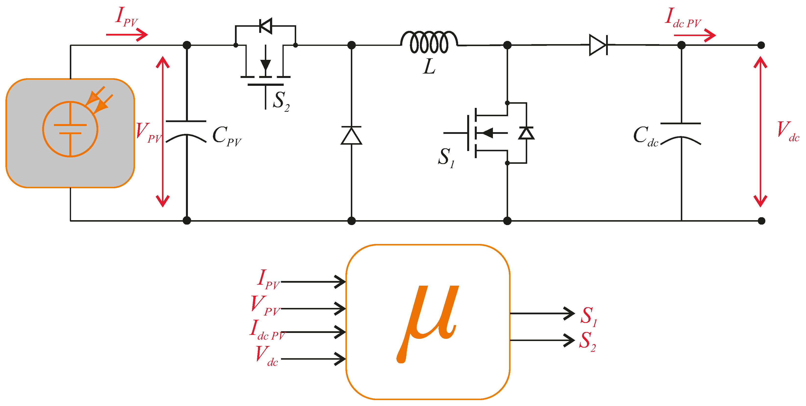
2.1. DC‒DC Converter
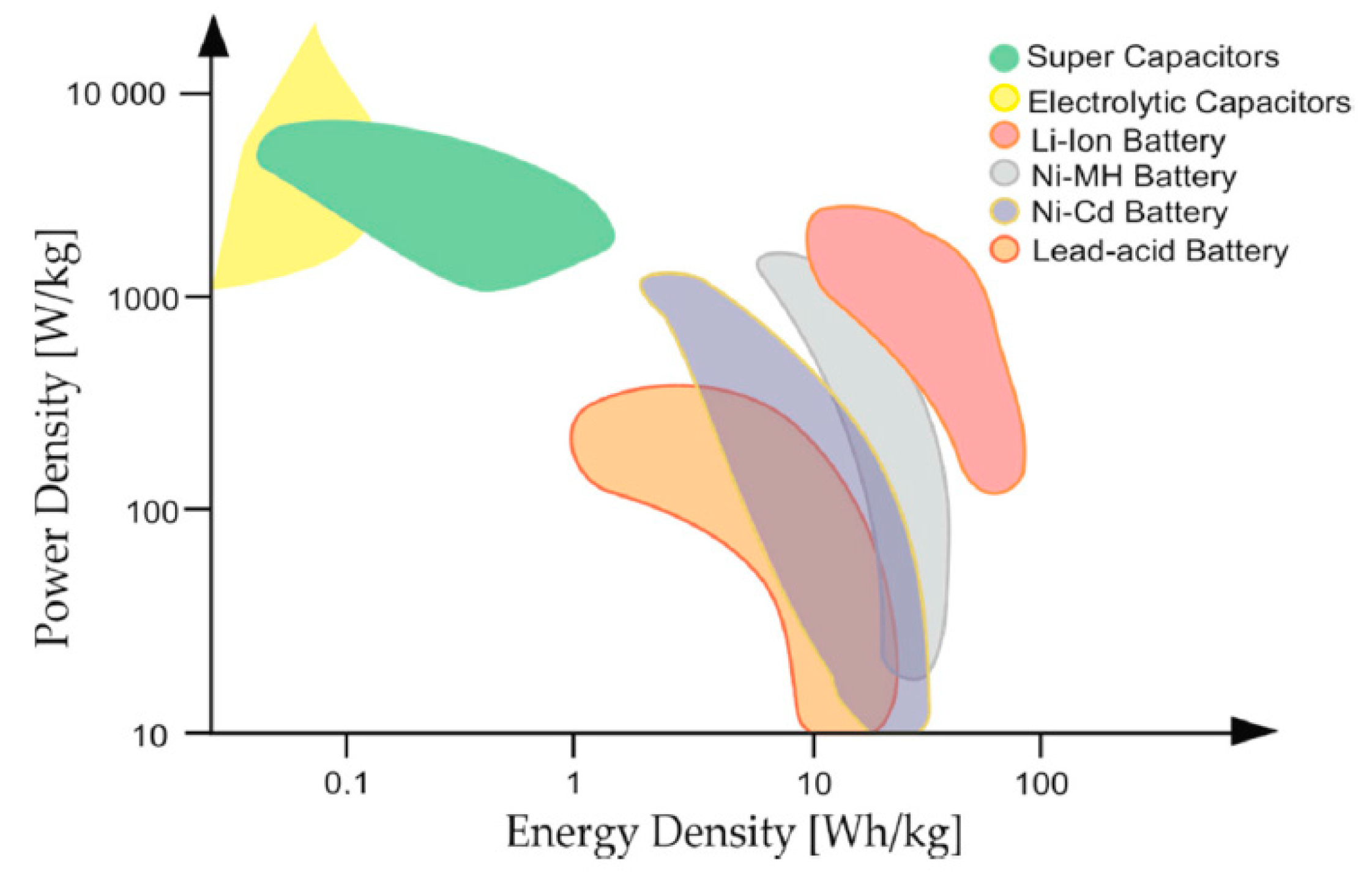
2.2. Storage Systems
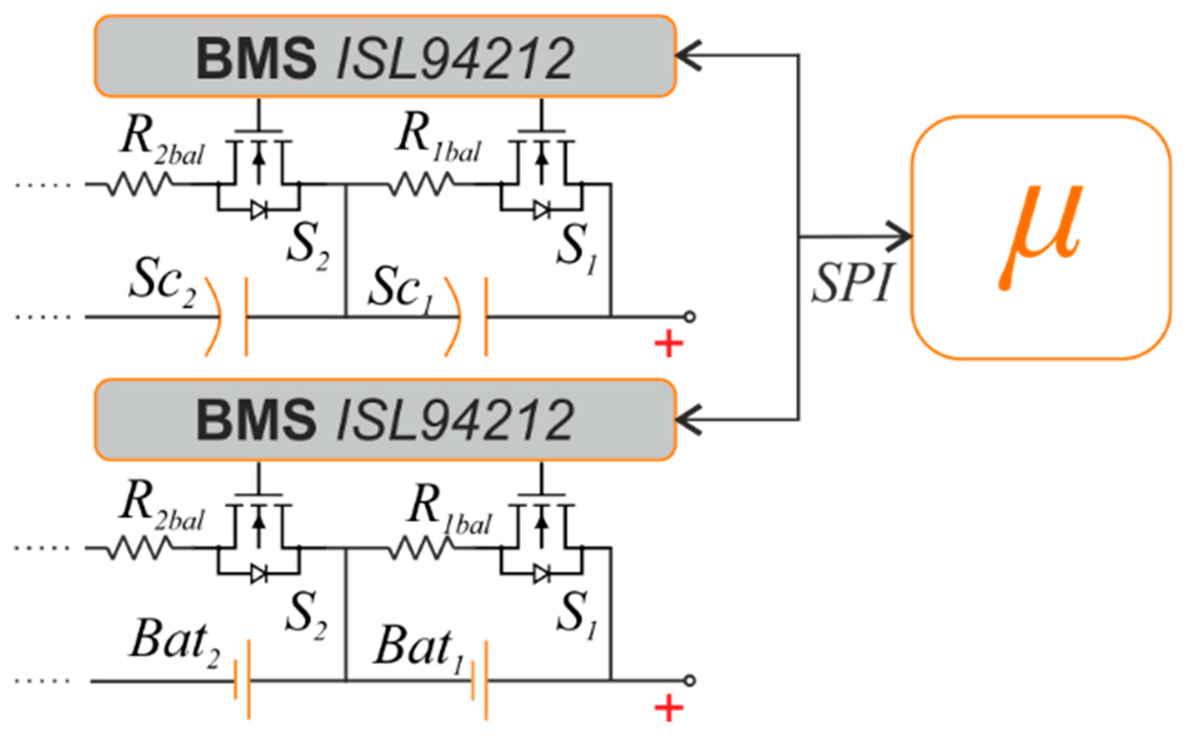
Balancing System
3. Control Scheme and Proposed Power Management Strategy
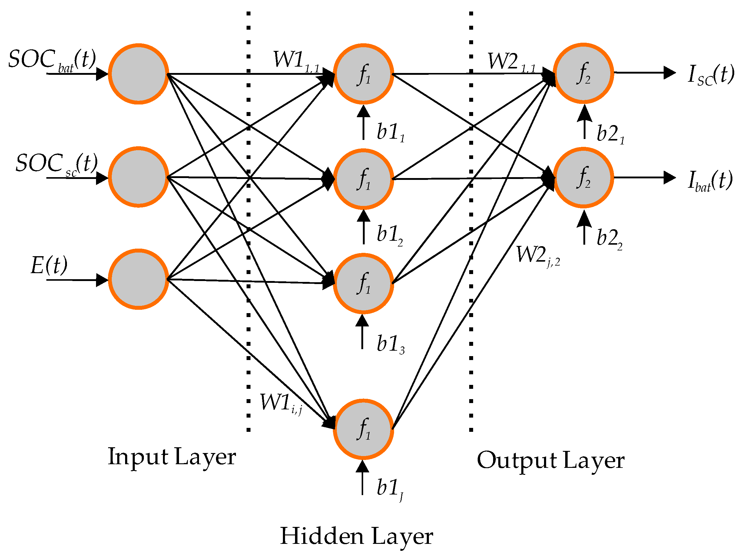
3.1. HESS Power Management Strategy
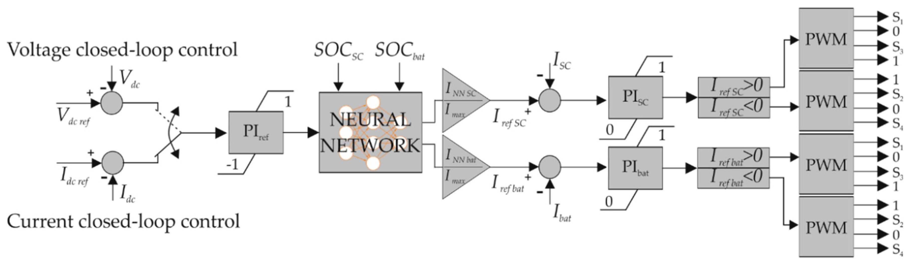
3.2. Control Scheme
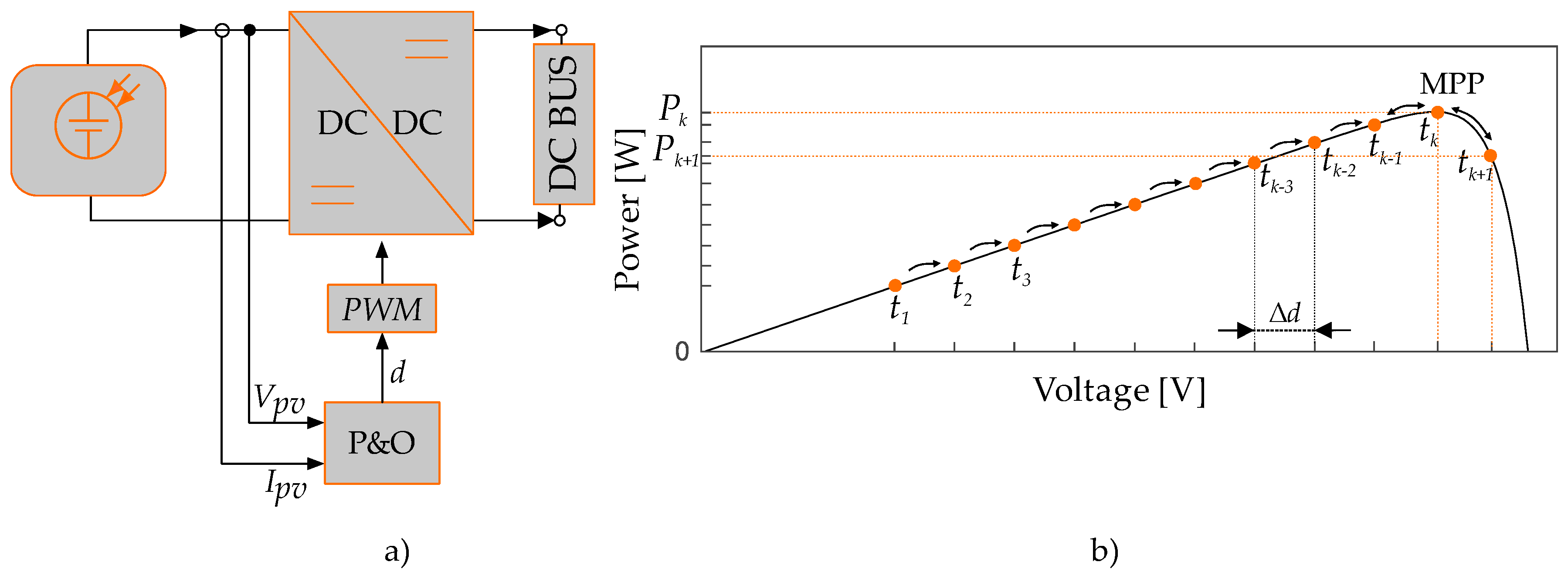
3.3. MPPT Algorithm
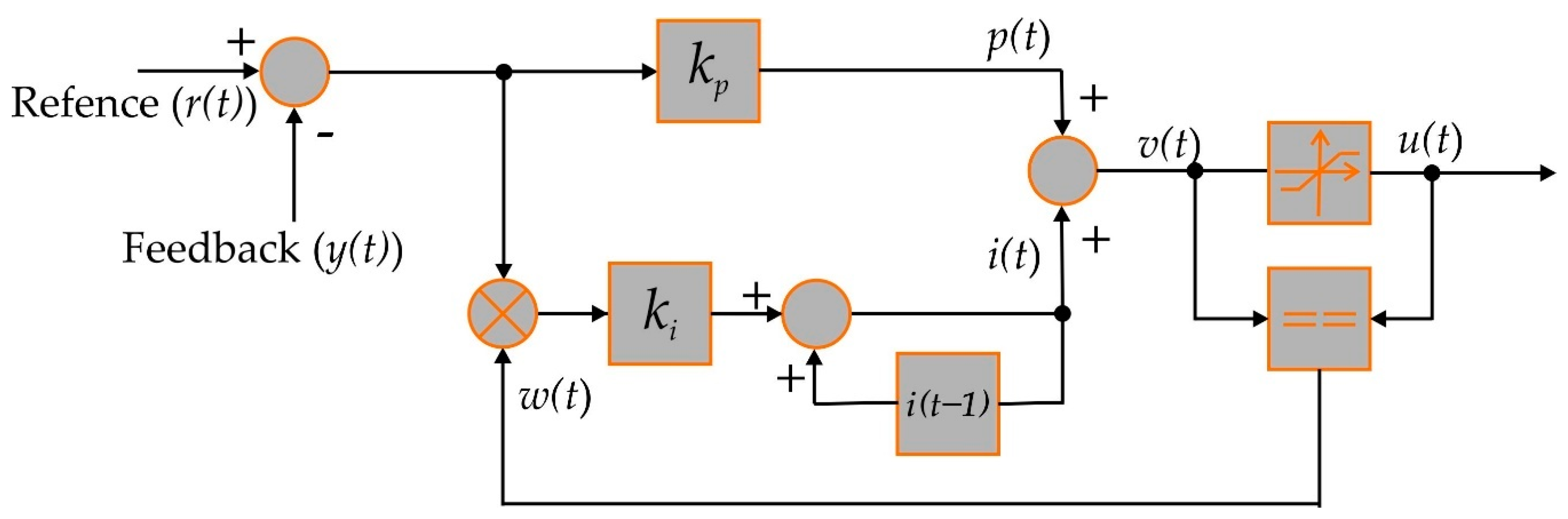
3.4. Proportional Integral Controller with Anti-Wind-Up Mechanism
PI Controllers Optimization
4. Computational Simulations
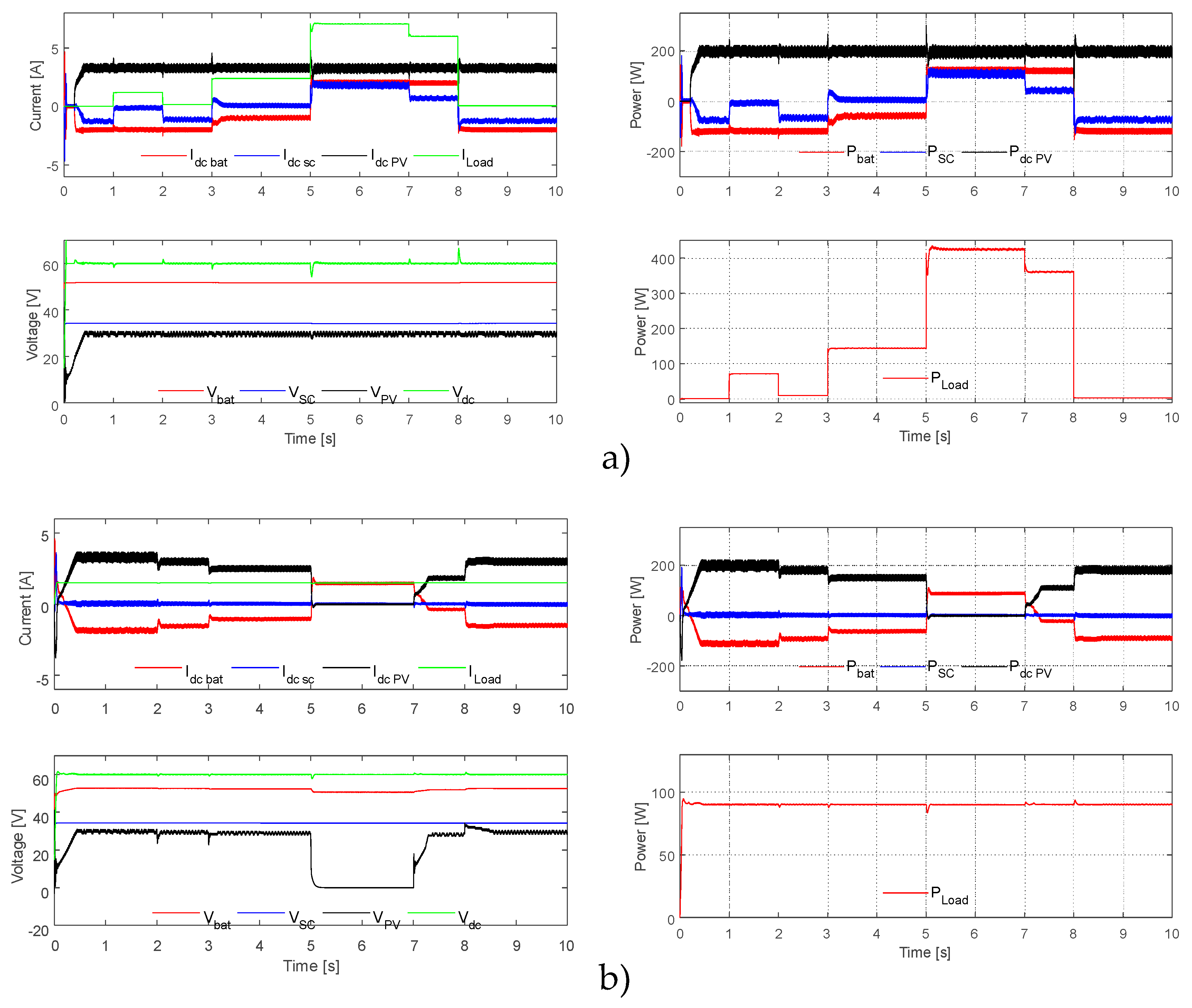
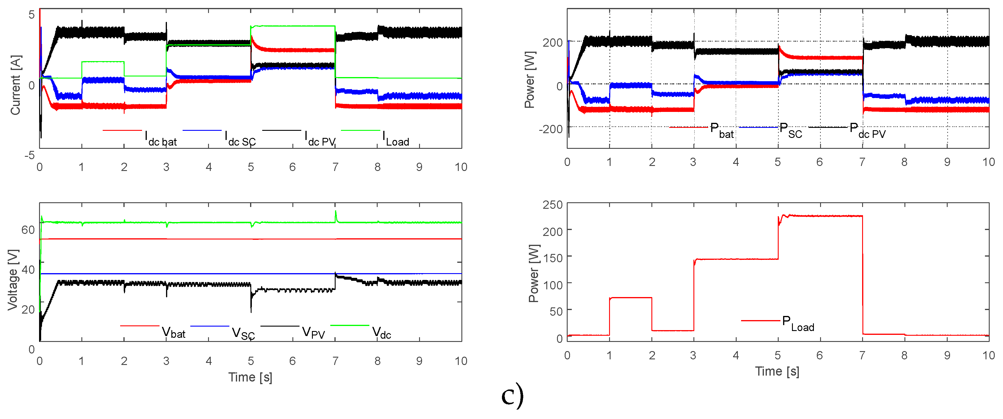
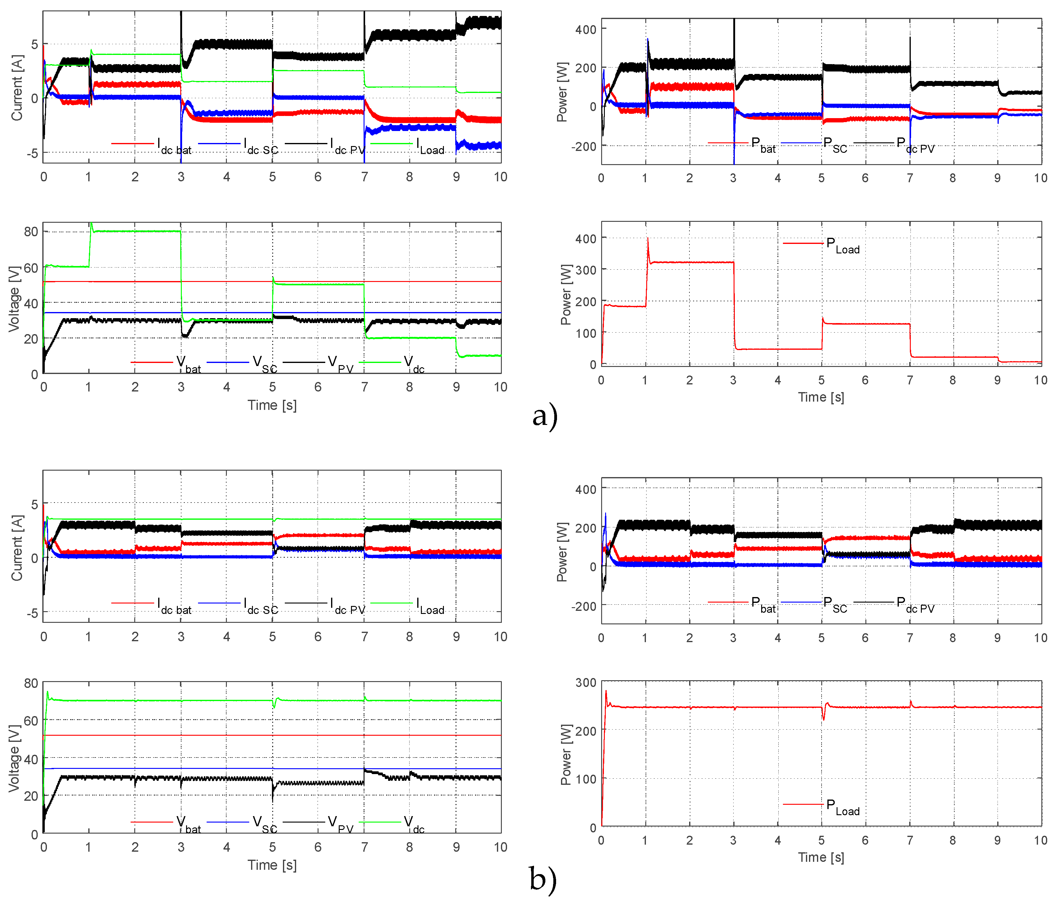
4.1. Computational Simulations with Voltage Closed-Loop Controller
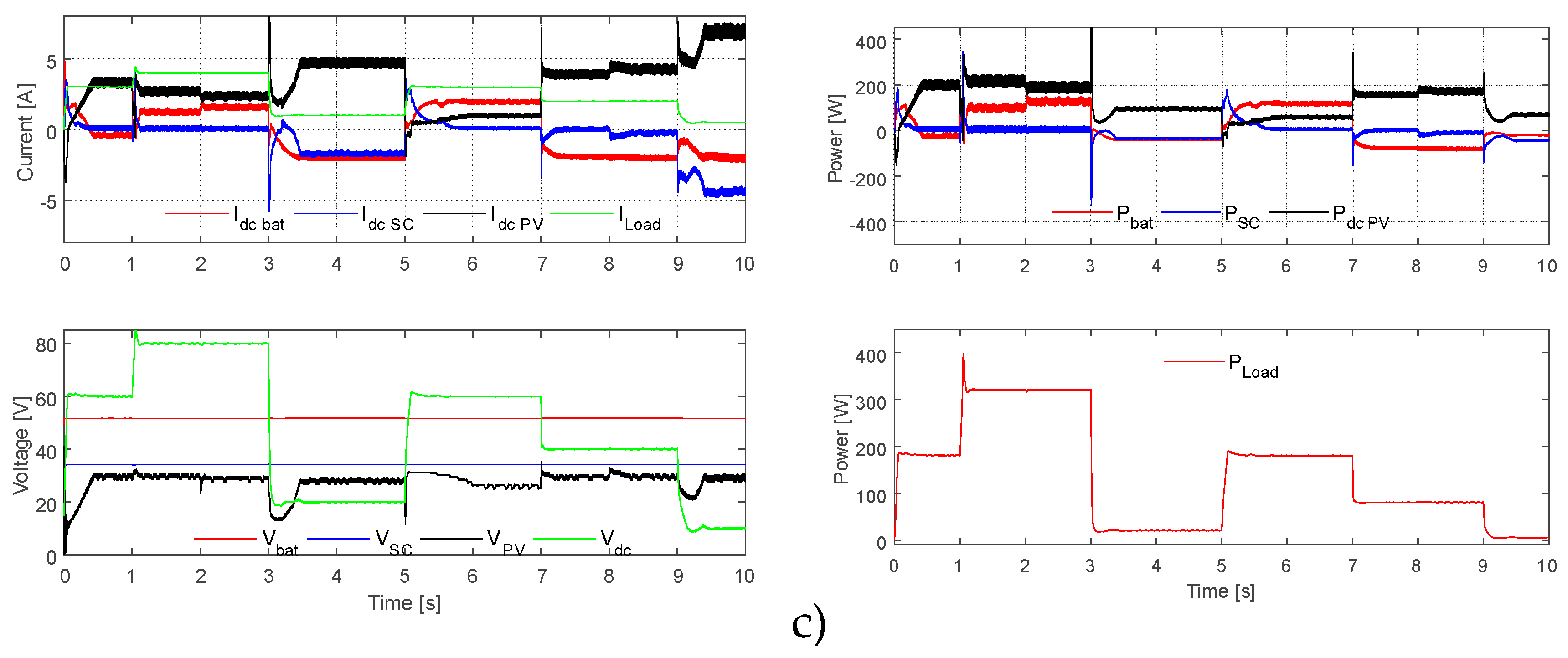
4.2. Computational Simulations with Current Closed-Loop Controller
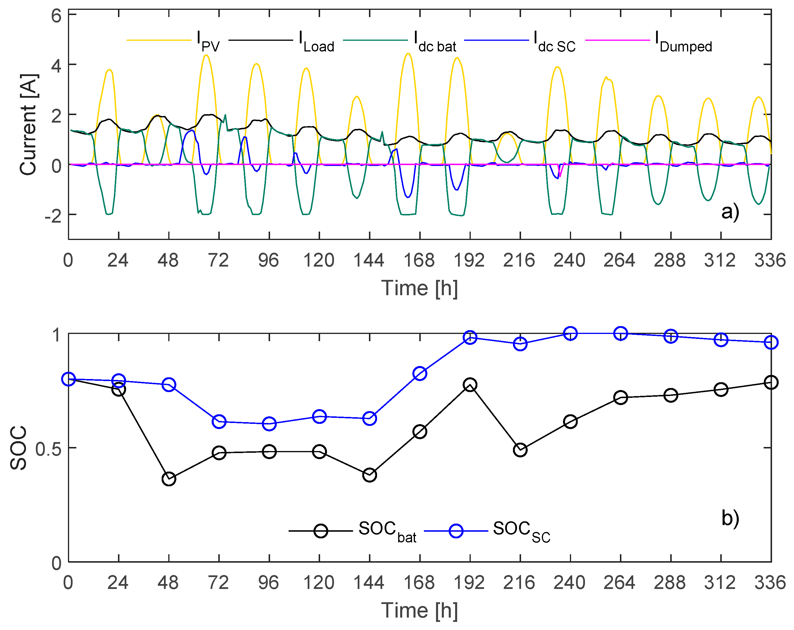
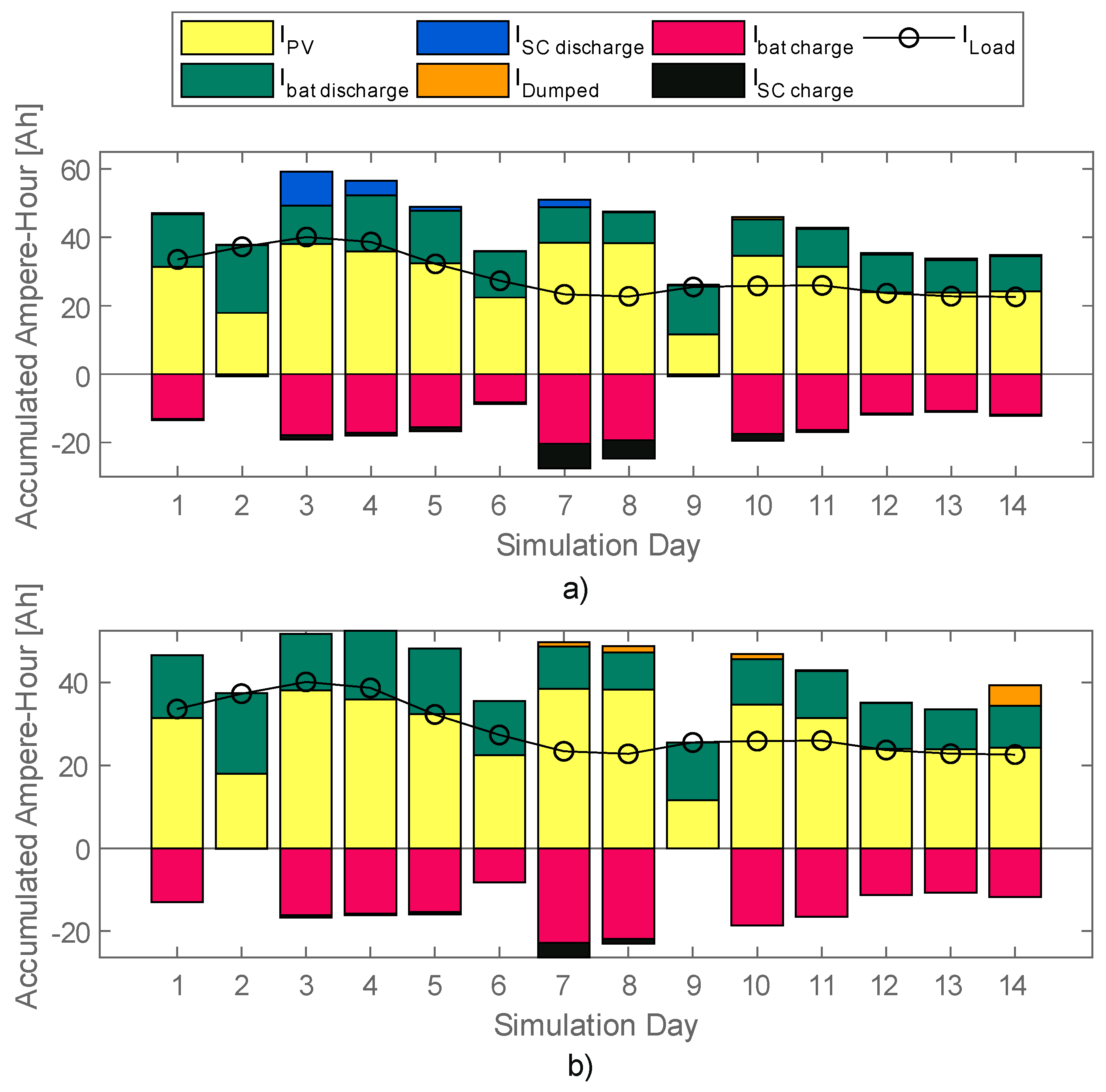
4.3. Performance under Long-Term Operation Scenario
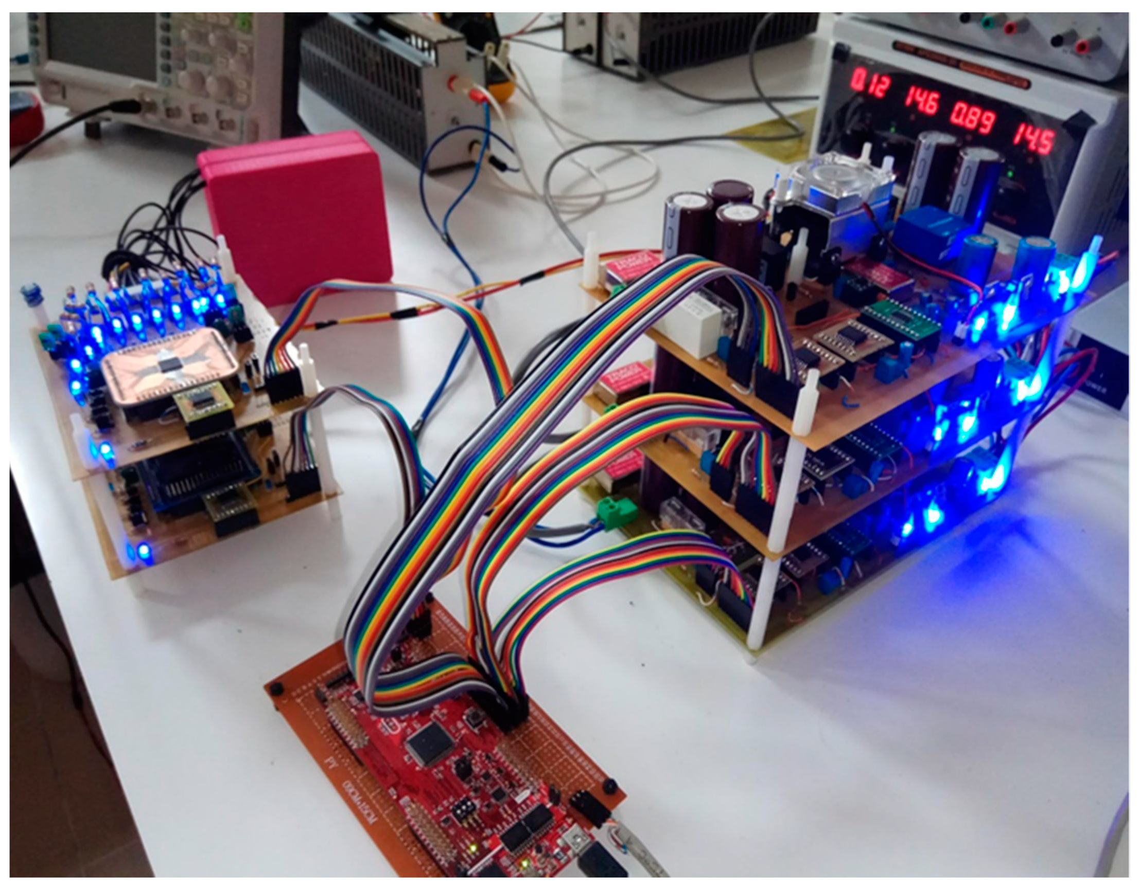
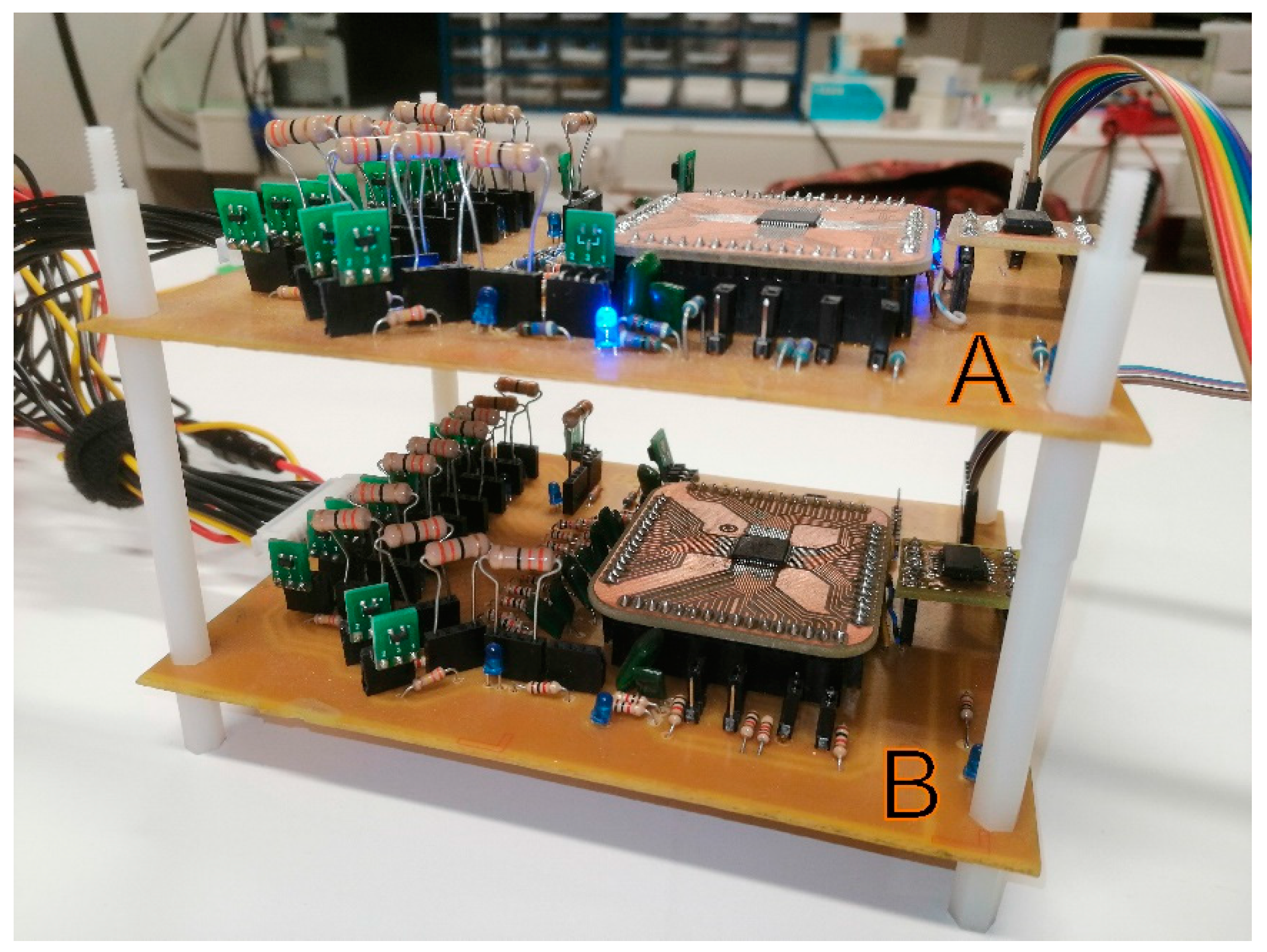
5. Experimental Results
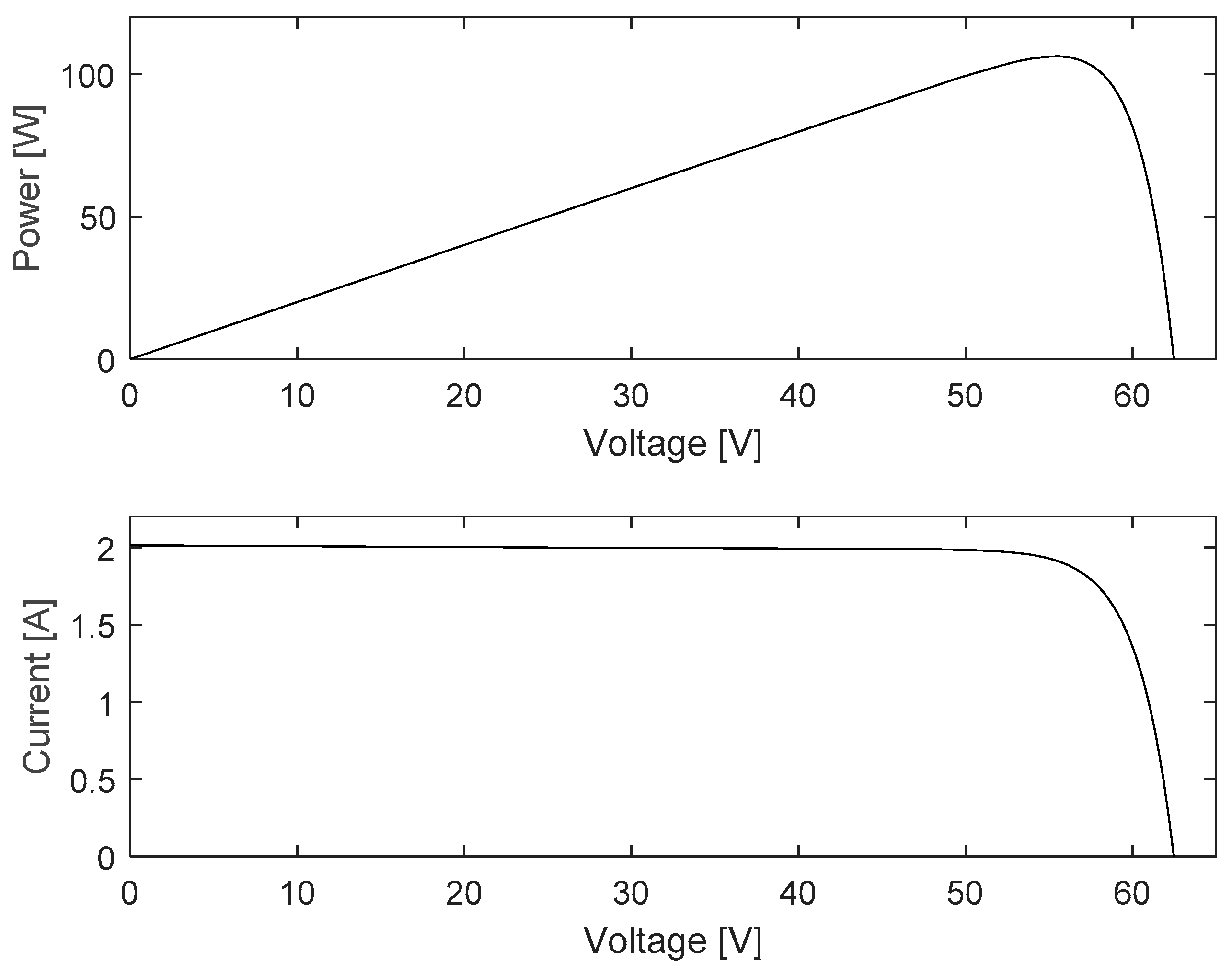
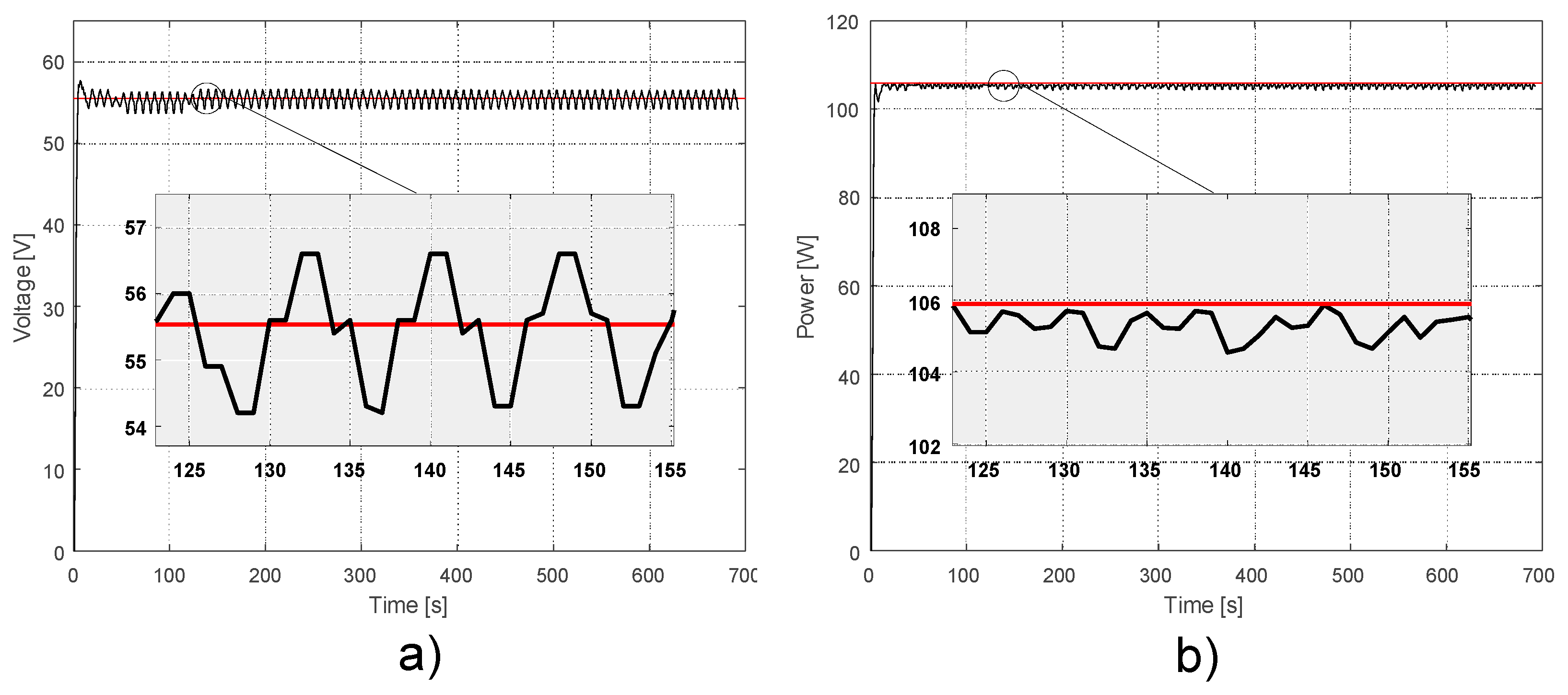
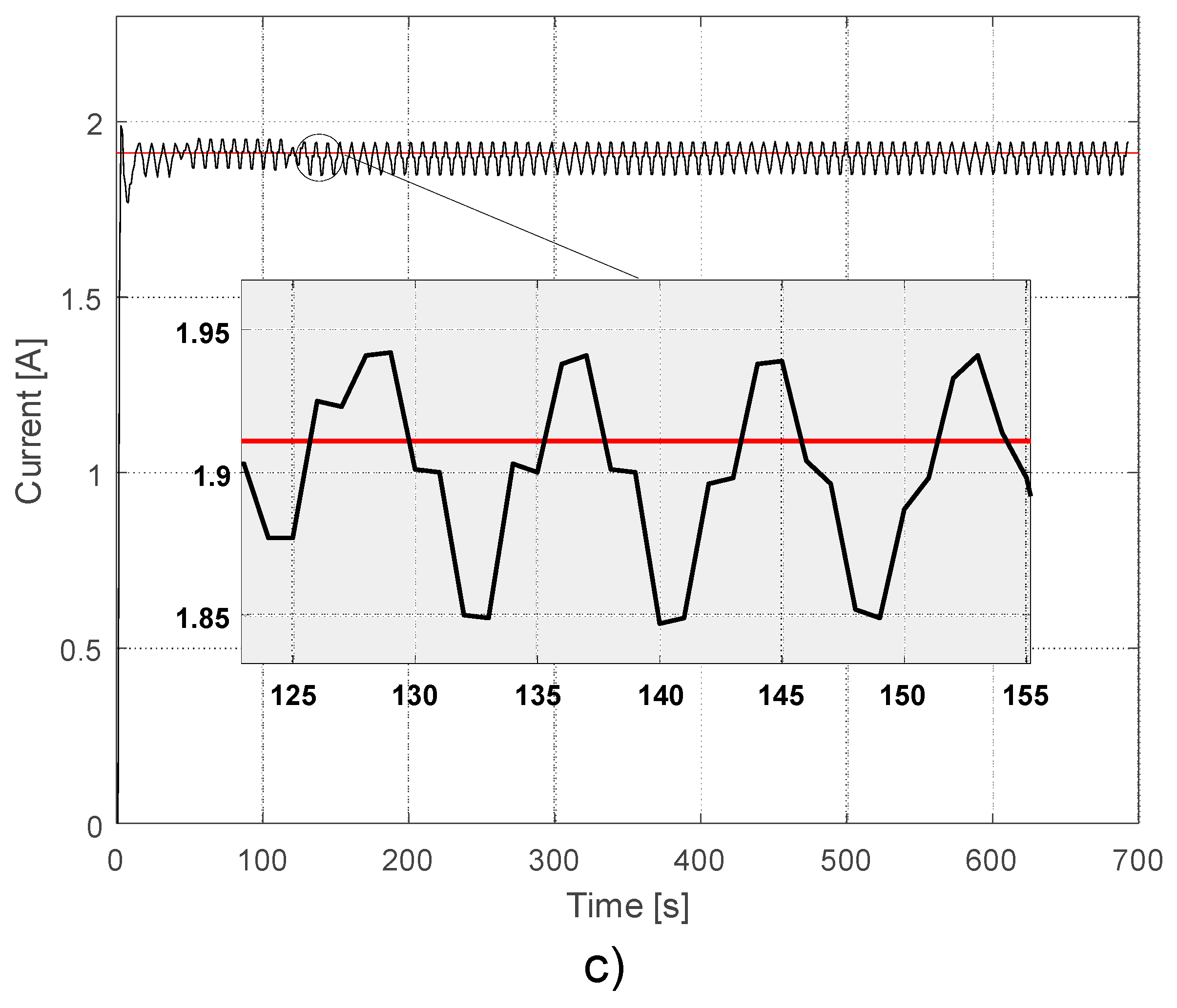
5.1. Photovoltaic Energy Extraction Results
5.2. HESS Controllers and Power Management Strategy Performance Test
6. Conclusions
Author Contributions
Funding
Acknowledgments
Conflicts of Interest
References
- Carreño-Ortega, A.; Galdeano-Gómez, E.; Pérez-Mesa, J.C.; Galera-Quiles, M.D.C. Policy and Environmental Implications of Photovoltaic Systems in Farming in Southeast Spain: Can Greenhouses Reduce the Greenhouse Effect? Energies 2017, 10, 761. [Google Scholar] [CrossRef]
- Jing, W.; Lai, C.H.; Wong, W.S.H.; Wong, M.L.D. Dynamic Power Allocation of Battery-Supercapacitor Hybrid Energy Storage for Standalone PV Microgrid Applications. Sustain. Energy Technol. Assess. 2017, 22, 55–64. [Google Scholar] [CrossRef]
- Chong, L.W.; Wong, Y.W.; Rajkumar, R.K.; Isa, D. An Optimal Control Strategy for Standalone PV System with Battery-Supercapacitor Hybrid Energy Storage System. J. Power Sources 2016, 331, 553–565. [Google Scholar] [CrossRef]
- Uddin, K.; Moore, A.D.; Barai, A.; Marco, J. The Effects of High Frequency Current Ripple on Electric Vehicle Battery Performance. Appl. Energy 2016, 178, 142–154. [Google Scholar] [CrossRef]
- Kan, S.Y.; Verwaal, M.; Broekhuizen, H. The Use of Battery-Capacitor Combinations in Photovoltaic Powered Products. J. Power Sources 2006, 162, 971–974. [Google Scholar] [CrossRef]
- Zhou, Z.; Benbouzid, M.; Frédéric Charpentier, J.; Scuiller, F.; Tang, T. A Review of Energy Storage Technologies for Marine Current Energy Systems. Renew. Sustain. Energy Rev. 2013, 18, 390–400. [Google Scholar] [CrossRef]
- Zuo, W.; Li, R.; Zhou, C.; Li, Y.; Xia, J.; Liu, J. Battery-Supercapacitor Hybrid Devices: Recent Progress and Future Prospects. Adv. Sci. 2017, 4, 1–21. [Google Scholar] [CrossRef] [PubMed]
- Choi, M.-E.; Kim, S.-W.; Seo, S.-W. Energy Management Optimization in a Battery/Supercapacitor Hybrid Energy Storage System. IEEE Trans. Smart Grid 2012, 3, 463–472. [Google Scholar] [CrossRef]
- Masih-Tehrani, M.; Ha’iri-Yazdi, M.R.; Esfahanian, V.; Safaei, A. Optimum Sizing and Optimum Energy Management of a Hybrid Energy Storage System for Lithium Battery Life Improvement. J. Power Sources 2013, 244, 2–10. [Google Scholar] [CrossRef]
- Allègre, A.L.; Trigui, R.; Bouscayrol, A. Different Energy Management Strategies of Hybrid Energy Storage System (HESS) Using Batteries and Supercapacitors for Vehicular Applications. In Proceedings of the 2010 IEEE Vehicle Power and Propulsion Conference (VPPC 2010), Lille, France, 1–3 September 2010. [Google Scholar] [CrossRef]
- Cao, J.; Emadi, A. A New Battery/Ultracapacitor Hybrid Energy Storage System for Electric, Hybrid, and Plug-in Hybrid Electric Vehicles. IEEE Trans. Power Electron. 2012, 27, 122–132. [Google Scholar] [CrossRef]
- Jiang, Z.; Dougal, R.A. Hierarchical Microgrid Paradigm for Integration of Distributed Energy Resources. In Proceedings of the 2008 IEEE Power and Energy Society General Meeting—Conversion and Delivery of Electrical Energy in the 21st Century, Pittsburgh, PA, USA, 20–24 July 2008; pp. 1–8. [Google Scholar] [CrossRef]
- Yuan, C.; Chen, K.; Chan, C.C.; Bouscayrol, A.; Shumei, C. Global Modeling and Control Strategy Simulation for a Hybrid Electric Vehicle Using Electrical Variable Transmission. In Proceedings of the 2008 IEEE Vehicle Power and Propulsion Conference, Harbin, China, 3–5 September 2008; pp. 1–5. [Google Scholar] [CrossRef]
- Tani, A.; Camara, M.B.; Dakyo, B. Energy Management Based on Frequency Approach for Hybrid Electric Vehicle Applications: Fuel-Cell/Lithium-Battery and Ultracapacitors. IEEE Trans. Veh. Technol. 2012, 61, 3375–3386. [Google Scholar] [CrossRef]
- Manandhar, U.; Tummuru, N.R.; Kollimalla, S.K.; Ukil, A.; Beng, G.H.; Chaudhari, K. Validation of Faster Joint Control Strategy for Battery- and Supercapacitor-Based Energy Storage System. IEEE Trans. Ind. Electron. 2018, 65, 3286–3295. [Google Scholar] [CrossRef]
- Kollimalla, S.K.; Mishra, M.K.; Narasamma, N.L. Design and Analysis of Novel Control Strategy for Battery and Supercapacitor Storage System. IEEE Trans. Sustain. Energy 2014, 5, 1137–1144. [Google Scholar] [CrossRef]
- Sun, L.; Feng, K.; Chapman, C.; Zhang, N. An Adaptive Power-Split Strategy for Battery-Supercapacitor Powertrain-Design, Simulation, and Experiment. IEEE Trans. Power Electron. 2017, 32, 9364–9375. [Google Scholar] [CrossRef]
- Montazeri-Gh, M.; Mahmoodi-k, M. Development a New Power Management Strategy for Power Split Hybrid Electric Vehicles. Transp. Res. Part D Transp. Environ. 2015, 37, 79–96. [Google Scholar] [CrossRef]
- Shengzhe, Z.; Kai, W.; Wen, X. Fuzzy Logic-Based Control Strategy for a Battery/Supercapacitor Hybrid Energy Storage System in Electric Vehicles. In Proceedings of the 2017 Chinese Automation Congress (CAC), Jinan, China, 20–22 October 2017; Volume 1. [Google Scholar]
- Won, J.S.; Langari, R. Intelligent Energy Management Agent for a Parallel Hybrid Vehicle—Part II: Torque Distribution, Charge Sustenance Strategies, and Performance Results. IEEE Trans. Veh. Technol. 2005, 54, 935–953. [Google Scholar] [CrossRef]
- Hajimiri, M.H.; Salmasi, F.R. A Fuzzy Energy Management Strategy for Series Hybrid Electric Vehicle with Predictive Control and Durability Extension of the Battery. In Proceedings of the 2006 IEEE Conference on Electric and Hybrid Vehicles, Pune, India, 18–20 December 2006; pp. 1–5. [Google Scholar] [CrossRef]
- Wang, Y.; Wang, W.; Zhao, Y.; Yang, L.; Chen, W. A Fuzzy-Logic Power Management Strategy Based on Markov Random Prediction for Hybrid Energy Storage Systems. Energies 2016, 9, 25. [Google Scholar] [CrossRef]
- Jing, W.; Hung Lai, C.; Wong, S.H.W.; Wong, M.L.D. Battery-Supercapacitor Hybrid Energy Storage System in Standalone DC Microgrids: Areview. IET Renew. Power Gener. 2017, 11, 461–469. [Google Scholar] [CrossRef]
- Wu, G.; Boriboonsomsin, K.; Barth, M.J. Development and Evaluation of an Intelligent Energy-Management Strategy for Plug-in Hybrid Electric Vehicles. IEEE Trans. Intell. Transp. Syst. 2014, 15, 1091–1100. [Google Scholar] [CrossRef]
- Wegmann, R.; Döge, V.; Becker, J.; Sauer, D.U. Optimized Operation of Hybrid Battery Systems for Electric Vehicles Using Deterministic and Stochastic Dynamic Programming. J. Energy Storage 2017, 14, 22–38. [Google Scholar] [CrossRef]
- Madanipour, V.; Montazeri-Gh, M.; Mahmoodi-K, M. Optimization of the Component Sizing for a Plug-in Hybrid Electric Vehicle Using a Genetic Algorithm. Proc. Inst. Mech. Eng. Part D J. Automob. Eng. 2016, 230, 692–708. [Google Scholar] [CrossRef]
- Paganelli, G.; Guerra, T.M.; Delprat, S.; Guezennec, Y.; Rizzoni, G. To Hybrid Fuel Cell Powered Vehicle. In Proceedings of the 15th IFAC World Congress, Barcelona, Spain, 21–26 July 2002; Volume 35. [Google Scholar] [CrossRef]
- Chen, Z.; Xiong, R.; Cao, J. Particle Swarm Optimization-Based Optimal Power Management of Plug-in Hybrid Electric Vehicles Considering Uncertain Driving Conditions. Energy 2016, 96, 197–208. [Google Scholar] [CrossRef]
- Xia, C.; Zhang, C. Power Management Strategy of Hybrid Electric Vehicles Based on Quadratic Performance Index. Energies 2015, 8, 12458–12473. [Google Scholar] [CrossRef]
- Borhan, H.; Member, S.; Vahidi, A.; Phillips, A.M.; Kuang, M.L.; Kolmanovsky, I.V.; Di Cairano, S. MPC-Based Energy Management of a Power-Split Hybrid Electric Vehicle. IEEE Trans. Control Syst. Technol. 2012, 20, 593–603. [Google Scholar] [CrossRef]
- Hredzak, B.; Agelidis, V.G.; Jang, M. A Model Predictive Control System for a Hybrid Battery-Ultracapacitor Power Source. IEEE Trans. Power Electron. 2014, 29, 1469–1479. [Google Scholar] [CrossRef]
- Guay, M.; Zhang, T. Adaptive Extremum Seeking Control of Nonlinear Dynamic Systems with Parametric Uncertainties. Automatica 2003, 39, 1283–1293. [Google Scholar] [CrossRef]
- Pisu, P.; Rizzoni, G. A Comparative Study of Supervisory Control Strategies for Hybrid Electric Vehicles. IEEE Trans. Control Syst. Technol. 2007, 15, 506–518. [Google Scholar] [CrossRef]
- Barelli, L.; Bidini, G.; Bonucci, F.; Ottaviano, A. Residential Micro-Grid Load Management through Arti Fi Cial Neural Networks. J. Energy Storage 2018, 17, 287–298. [Google Scholar] [CrossRef]
- Sharma, R.K.; Mishra, S. Dynamic Power Management and Control of a PV PEM Fuel-Cell-Based Standalone Ac/Dc Microgrid Using Hybrid Energy Storage. IEEE Trans. Ind. Appl. 2018, 54, 526–538. [Google Scholar] [CrossRef]
- Wai, L.; Wong, Y.W.; Rajkumar, R.K.; Rajkumar, R.K.; Isa, D. Hybrid Energy Storage Systems and Control Strategies for Stand-Alone Renewable Energy Power Systems. Renew. Sustain. Energy Rev. 2016, 66, 174–189. [Google Scholar] [CrossRef]
- Akcayol, M.A. Application of Adaptive Neuro-Fuzzy Controller for SRM. Adv. Eng. Softw. 2004, 35, 129–137. [Google Scholar] [CrossRef]
- Yumurtaci, R. Role of Energy Management in Hybrid Renewable Energy Systems: Case Study-Based Analysis Considering Varying Seasonal Conditions. Turk. J. Electr. Eng. Comput. Sci. 2013, 21, 1077–1091. [Google Scholar] [CrossRef]
- Song, Y.D.; Cao, Q.; Du, X.; Karimi, H.R. Control Strategy Based on Wavelet Transform and Neural Network for Hybrid Power System. J. Appl. Math. 2013, 2013, 1–8. [Google Scholar] [CrossRef]
- Shen, J.; Khaligh, A.; Member, S. A Supervisory Energy Management Control Strategy in a Battery Ultracapacitor Hybrid Energy Storage System. IEEE Trans. Transp. Electr. 2015, 1, 223–231. [Google Scholar] [CrossRef]
- Velho, R.; Beirão, M.; Calado, M.; Pombo, J.; Fermeiro, J.; Mariano, S. Management System for Large Li-Ion Battery Packs with a New Adaptive Multistage Charging Method. Energies 2017, 10, 605. [Google Scholar] [CrossRef]
- Waffler, S.; Kolar, J.W. A Novel Low-Loss Modulation Strategy for High-Power Bidirectional Buck + Boost Converters. IEEE Trans. Power Electron. 2009, 24, 1589–1599. [Google Scholar] [CrossRef]
- Liu, K.-B.; Liu, C.Y.; Liu, Y.H.; Chien, Y.C.; Wang, B.S.; Wong, Y.S. Analysis and Controller Design of a Universal Bidirectional DC-DC Converter. Energies 2016, 9, 501. [Google Scholar] [CrossRef]
- Vazquez, S.; Lukic, S.M.; Galvan, E.; Franquelo, L.G.; Carrasco, J.M. Energy Storage Systems for Transport and Grid Applications. IEEE Trans. Ind. Electron. 2010, 57, 3881–3895. [Google Scholar] [CrossRef]
- Glavin, M.E.E.; Chan, P.K.W.; Armstrong, S.; Hurley, W.G.G. A Stand-Alone Photovoltaic Supercapacitor Battery Hybrid Energy Storage System. In Proceedings of the 2008 13th International Power Electronics and Motion Control Conference, Poznan, Poland, 1–3 September 2008; pp. 1688–1695. [Google Scholar] [CrossRef]
- Sathishkumar, R.; Kollimalla, S.K.; Mishra, M.K. Dynamic Energy Management of Micro Grids Using Battery Super Capacitor Combined Storage. In Proceedings of the 2012 Annual IEEE India Conference (INDICON), Kochi, India, 7–9 December 2012; pp. 1078–1083. [Google Scholar] [CrossRef]
- Zhang, G.; Tang, X.; Qi, Z. Research on Battery Supercapacitor Hybrid Storage and Its Application in MicroGrid. In Proceedings of the 2010 Asia-Pacific Power and Energy Engineering Conference, Chengdu, China, 28–31 March 2010; pp. 5–8. [Google Scholar] [CrossRef]
- Steinhorst, S.; Shao, Z.; Chakraborty, S.; Kauer, M.; Li, S.; Lukasiewycz, M.; Narayanaswamy, S.; Rafique, M.U.; Wang, Q. Distributed Reconfigurable Battery System Management Architectures. In Proceedings of the 2016 21st Asia and South Pacific Design Automation Conference (ASP-DAC), Macau, China, 25–28 January 2016; pp. 429–434. [Google Scholar] [CrossRef]
- Japkowicz, N. Supervised versus Unsupervised Binary-Learning by Feedforward Neural Networks. Mach. Learn. 2001, 42, 97–122. [Google Scholar] [CrossRef]
- Hannan, M.A.; Member, S. State-of-the-Art and Energy Management System of Lithium-Ion Batteries in Electric Vehicle Applications: Issues and Recommendations. IEEE Access 2018, 6, 19362–19378. [Google Scholar] [CrossRef]
- Tobón, A.; Peláez-Restrepo, J.; Villegas-Ceballos, J.P.; Serna-Garcés, S.I.; Herrera, J.; Ibeas, A. Maximum Power Point Tracking of Photovoltaic Panels by Using Improved Pattern Search Methods. Energies 2017, 10, 1316. [Google Scholar] [CrossRef]
- Wang, S.C.; Liu, Y.H. A PSO-Based Fuzzy-Controlled Searching for the Optimal Charge Pattern of Li-Ion Batteries. IEEE Trans. Ind. Electron. 2015, 62, 2983–2993. [Google Scholar] [CrossRef]
- Zhang, Y.; Jiang, Z.; Yu, X. Control Strategies for Battery/Supercapacitor Hybrid Energy Storage Systems. In Proceedings of the 2008 IEEE Energy 2030 Conference, Atlanta, GA, USA, 17–18 November 2008; pp. 1–6. [Google Scholar] [CrossRef]


| BOOST | BUCK | BUCK-BOOST | ||||
|---|---|---|---|---|---|---|
| Discharge | Charge | Discharge | Charge | Discharge | Charge | |
| S1 | 1 | 1 | ||||
| S2 | 0 | 0 | 0 | |||
| S3 | 0 | 0 | 0 | |||
| S4 | 1 | 1 | 1 | |||
| SOC | 0 < E(t) < Imd bat | E(t) > Imd bat | ||
|---|---|---|---|---|
| SC | Li-ion | SC | Li-ion | |
| SOCbat < SOCbat min & SOCsc < SOCsc min | Safety condition | |||
| SOCbat < SOCbat min & SOCsc > SOCsc min | E(t) × Imax | 0 | E(t) × Imax | 0 |
| SOCbat > SOCbat min & SOCsc > SOCsc min | 0 | E(t) × Imax | (E(t) − Imax bat) × Imd bat | Imd bat × Imax |
| SOCbat > SOCbat min & SOCsc < SOCsc min | 0 | E(t) × Imax | 0 | Imd bat × Imax |
| SOC | Imc bat < E(t) < 0 | E(t) < Imc bat | ||
|---|---|---|---|---|
| SC | Li-ion | SC | Li-ion | |
| SOCbat > SOCbat max & SOCsc = SOCsc max | Safety condition | |||
| SOCbat < SOCbat max & SOCsc = SOCsc max | 0 | −E(t) × Imax | 0 | Imc bat × Imax |
| SOCbat < SOCbat max & SOCsc ≠ SOCsc max | 0 | −E(t) × Imax | −(E(t) − Imc bat) × Imax | Imc bat × Imax |
| SOCbat > SOCbat max & SOCsc ≠ SOCsc max | −E(t) × Imax | 0 | −E(t) × Imax | 0 |
| Controller | Parameters | Current Closed-Loop Control Scheme | Voltage Closed-Loop Control Scheme |
|---|---|---|---|
| PIbat | ki | 0.0043074 | 0.0206 |
| kp | 1.7812 | 0.0514 | |
| PIsc | ki | 0.001 | 0.0001 |
| kp | 0.7789 | 0.9377 | |
| PIref | ki | 0.005966 | 0.041 |
| kp | 4 | 4.6144 |
© 2019 by the authors. Licensee MDPI, Basel, Switzerland. This article is an open access article distributed under the terms and conditions of the Creative Commons Attribution (CC BY) license (http://creativecommons.org/licenses/by/4.0/).
Share and Cite
Faria, J.; Pombo, J.; Calado, M.d.R.; Mariano, S. Power Management Control Strategy Based on Artificial Neural Networks for Standalone PV Applications with a Hybrid Energy Storage System. Energies 2019, 12, 902. https://doi.org/10.3390/en12050902
Faria J, Pombo J, Calado MdR, Mariano S. Power Management Control Strategy Based on Artificial Neural Networks for Standalone PV Applications with a Hybrid Energy Storage System. Energies. 2019; 12(5):902. https://doi.org/10.3390/en12050902
Chicago/Turabian StyleFaria, João, José Pombo, Maria do Rosário Calado, and Sílvio Mariano. 2019. "Power Management Control Strategy Based on Artificial Neural Networks for Standalone PV Applications with a Hybrid Energy Storage System" Energies 12, no. 5: 902. https://doi.org/10.3390/en12050902
APA StyleFaria, J., Pombo, J., Calado, M. d. R., & Mariano, S. (2019). Power Management Control Strategy Based on Artificial Neural Networks for Standalone PV Applications with a Hybrid Energy Storage System. Energies, 12(5), 902. https://doi.org/10.3390/en12050902