1. Introduction
It is known that mining operations are heavily reliant on energy due to their intrinsic nature. However, subsurface mining operations taking the lead in terms of heavy energy demands. In fact, they demand roughly 20% more energy than open pit mines per tonne of ore extracted and processed [
1]. This difference is mainly due to mine air heating, ventilation and refrigeration (HVAC) purposes. Although it may depend on several other factors, in a general sense, a typical underground mine may need up to 100 kWh of energy per tonne of ore extracted and processed [
1].
Mining is a locomotive industry in Canada and, just by itself, it occupies a significant portion of the domestic economy by bringing some
$56 billion contribution to the GDP (gross domestic product) and employing more than half-a-million people [
2]. A significant percentage of the Canadian mines are relying on fossil fuel driven energy generation systems to keep operating [
3]. This energy dependency and attached GHG (greenhouse gas) emissions pulls the spotlights over the industry questioning its energy profile in the era of clean energy. According to Thollander and Ottosson, several studies are already assuming this; potential issues related to the environmental and energy aspects of the mining industry are soon to be harshly regulated based on the forthcoming economic and regulatory means [
4]. This might possibly stretch the socio-environmental and financial success of future and existing mining operations. In this perspective, mining companies are aiming to lessen their energy and environmental footprints with cleaner solutions by targeting their most ‘energy-intensive’ activities. This study aims to outline the end-to-end process of one of these effective, alternative solutions, shortly referred as ‘lake cooling’.
Conventional mine refrigeration systems use mechanical refrigeration methods and they rely on the energy intensive, compression cycles [
5]. Additionally, installation and operational expenses of conventional ambient air conditioning systems can result in a considerable financial burden for companies due to attached heavy machinery requirements. Strongly depending on the operational needs, a typical underground Canadian mine may require up to
$4.5 million/year worth of ventilation air and
$1–3 million/year worth of refrigeration provision [
1,
6,
7,
8,
9]. Additionally, the associated CAPEX (capital expenditure) of similar scale HVAC (heating ventilation and air conditioning) implementations may total up to
$50 million [
8]. A similarly sized underground mine HVAC system can be confidently considered to deal with hours of cooling duty with tens of megawatts of installed power. Moreover, tons of GHG emissions per year might as well be associated with such cooling strategies, if they are located off-grid and obliged to be fed with energy from fossil fuels. There is a good potential to change all these expenditures and energy related issues of mine cooling systems by substituting it with lake cooling as it seems to show a better harmony with the environment.
Shortly, deep lake cooling system proposed here suggests utilization of naturally available chilled water sources as coolant, substituting the conventional mine refrigeration system. It is crucial to note that, although there are many benefits that can be associated to lake cooling, it should be kept in mind that it requires existence of certain physical conditions (i.e., physical size of the surface water, geographic conditions and depth of the lake).
This paper not only aims to provide a detailed background information about surface water cooling systems, it also investigates a well descriptive, real-life Canadian example to better identify the state of the art and associated financial assessments by using a realistic data set.
Finally, it is worthwhile to note that this paper merely contains information regarding a specific Canadian example and does not provide generic studies based on project specific constraints, such as lake-mine distance, lake size and depth, solar irradiation capacity, etc. These dimensions are strongly recommended to be examined within their own scope in assessing the financial outcomes of a particular project. All of this information is strongly tentative from project to project and shall be considered within the individual framework of the project proposal.
1.1. Technical Background
1.1.1. Heat Load of Mines
There are several sources of heat in a complex mining environment and each one of them are usually case specific. However, according to several studies listed in [
1] exercising any subsurface mining activity at depths greater than 2000 m increases the impact of auto-compression component so significantly that mostly this kind of operations require mine air refrigeration [
1]. In addition to auto-compression, it is very well known that mines are also challenged by the heat emission from equipment fleet, U/G (underground) auxiliary machinery (pumps, electric sub-stations, fans, and so on) and strata. For a complex subsurface mining network, associated heat sources are summarized by de la Vergne [
1], as follows in
Table 1.
To elaborate more on stratification and geothermal gradient one can simply expect to have different behaviors on different geological settings. As Rothstein [
10] mentions in his work, the geothermal gradient of the stratification may range between 15°C/km to 50°C/km and this creates additional heat load for the mine ambient. Man-chao provides some examples in his study [
11] regarding the ambient air of some deep South African mines reaching up to 50 °C at depths of 3300 m. Kenny et al. states this figure as 40 °C beyond 2000 m [
12]. Nonetheless, North American standards state that maximum allowable conditions are way less than those are stated by Man-chao and Kenny et al.
As summarized in
Table 2 below by ASHRAE (American Society of Heating, Refrigerating and Air-Conditioning Engineers) [
13], there are different temperature ranges allowing different working limits for underground working networks. Accordingly, most of the standardized North American mines aim to stay in the maximum range of 27–29 °C wet-bulb temperature to prevent hyperthermia induced health and safety issues.
1.1.2. Deep Lake Cooling Systems
Large surface water bodies, (i.e., large-scale lakes) form thermal stratifications due to water flow regimes and seasonal temperature changes [
14]. Throughout the year, these thermal layers may be subjected to swift turnarounds allowing stratifications within the water body. Across these layers, there is a zone named as ‘thermocline’ that shows sharp temperature decline allowing the layer below, also known as ‘hypolimnion’ to be thermally more stable and relatively colder year-round [
15,
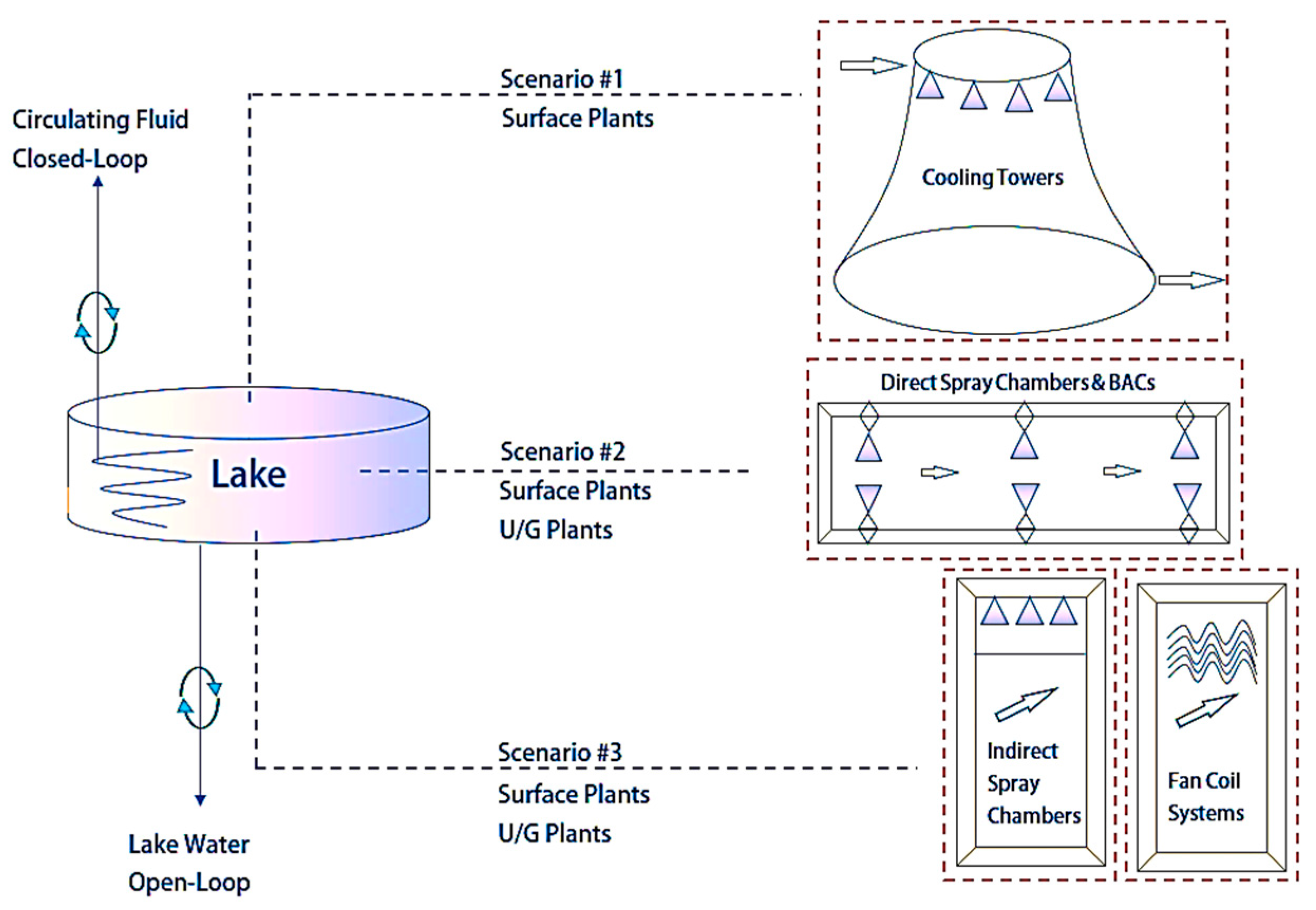
16]. Deep lake mine cooling system suggests reaching out to this colder water body and extracting the coolth by employment of either open-loop or closed-loop heat exchanging systems. A very brief schematics is presented in
Figure 1 below.
Deep lake cooling systems can be a very elegant solution to outsource the indispensable energy burden caused by the conventional refrigeration systems. However, success of the applicability of deep lake cooling systems is highly attached to the financial feasibility of the projects over their conventional counterparts. Realistically, there is no given recipe in deploying such systems as the profitability of these projects are strongly based on the physical limiting factors, such as proximity of the cold-water resources, terrain conditions, size of the water sources, temperature distribution within the lake body, and accessibility of the associated technology.
These conditions are highly project dependent and each one of them can turn out to be a project specific engineering challenge in the way of employment of lake cooling systems. Therefore, a proper financial assessment of such projects should be well-studied within their own framework for the given operating conditions of each mining operation.
1.1.3. Water Looping Systems
Loop characteristics of a deep-lake mine cooling system is dictated by the technique used for the coolth extraction. Mainly, there are two different techniques exist that allows the coolth extraction from hypolimnion, namely; closed-loop systems and open-loop systems.
In the former system, rather than displacing the lake water to another location, a helical pipeline network is simply sunk to the hypolimnion depth and a circulating water is pumped to pass through the network allowing the heat exchange during the circulation. A very good example of this case can be found in Toronto, Ontario, Canada operating as a district cooling system which employs a closed-loop system buried under the Lake Ontario [
17].
However, in the latter technique, the lake water is taken out via submerged pump/pipe system and sent to the destination where cooling is aimed to be achieved. Note that, depending on the water utilization scheme additional water treatment process may also be incurred having displaced/replaced a natural source governed by the provincial regulations. A very brief representation of these systems can be seen in
Figure 1. In any case, once the coolth from the hypolimnion of the lake is extracted, the cold water is used to cool the mine air at the mine site by employment of several methods to be covered in the next section.
1.1.4. Direct or Indirect Cooling of the Mine Air
Regardless from the circulating media (i.e., mine water in a closed-loop or lake water in an open-loop) the heat exchanging process from water to air and how is it achieved also matters dearly. In fact, the way the coolth is dumped to the mine air may impact the ultimate project financials very significantly. Similar to the techniques introduced in water looping systems, mine air cooling systems can also be distinguished based on the interaction of the fluids involved in the heat exchanging process.
Accordingly, the first heat exchanging mechanism is named as ‘direct cooling’. In direct cooling, the circulating water is simply sprayed over a flowing body of hot air in a chamber to remove its heat [
18]. These systems are also referred as ‘spray cooling’ systems. In this type of cooling systems, chilled water (discrete phase fluid) is sent to pressurized nozzles and gets into physical contact with hot air (continuous phase fluid) after leaving the nozzle outlet. Therefore, the heat exchange happens through physical contact. As McPherson states in this type of direct cooling techniques, latent heat transfer due to evaporation is usually negligible and most of the heat transfer happens via conduction between the fluid molecules [
18].
In contrast to the first technique, in the second technique the heat exchanging mechanism is named as ‘indirect cooling’. Conversely, in this cooling technique, chilled water does not come into touch with mine air by no means and loops in a closed system. In these systems, the heat exchange between cold and hot stream is either achieved via fan-coil heat exchangers or closed-loop heat exchanging chambers as stated by Lin [
19]. Both systems are simply represented in
Figure 1 for visualization.
1.1.5. Advantages of Spray Cooling Systems
Liquid cooling technologies have been out in the market for decades. There are numerous methods of employing liquid phase cooling techniques. However, as Kim states in his paper [
20], spray cooling methods stand out amongst the others with their relatively higher thermal flux capacities and this can be deemed as the biggest advantage of spray cooling systems [
20]. In fact, as Alkhedhair and his colleagues explain in their work, spray cooling became indispensably effective cooling technique in many fields of application [
21] and up to 14 °C of temperature drops can be achieved according to wind-tunnel tests conducted by Sureshkumar and his colleagues [
22,
23].
Nonetheless, spray cooling is a ‘technologically mature but scientifically yet to be fully understood’ phenomenon due to diversity of complex thermal impacts of different droplet characteristics. At this point, it is important to mention that the thermodynamic processes associated with the droplet size is mathematically sophisticated and conceptually reaches beyond the scope of this paper. Yet, shortly, it can be said that while smaller size, atomized droplets are providing latent cooling due to evaporation, cooling via larger droplet sizes are mostly based on conduction [
18,
24] and this type of cooling is more relevant for large scale spray cooling systems employed in mining applications. Therefore, empirical designs for such cooling systems are very effective and deemed to be sufficient in FEL (front-end loading) level designs. Correspondingly, this work investigates them by using the methodologies as mostly stated by McPherson [
18].
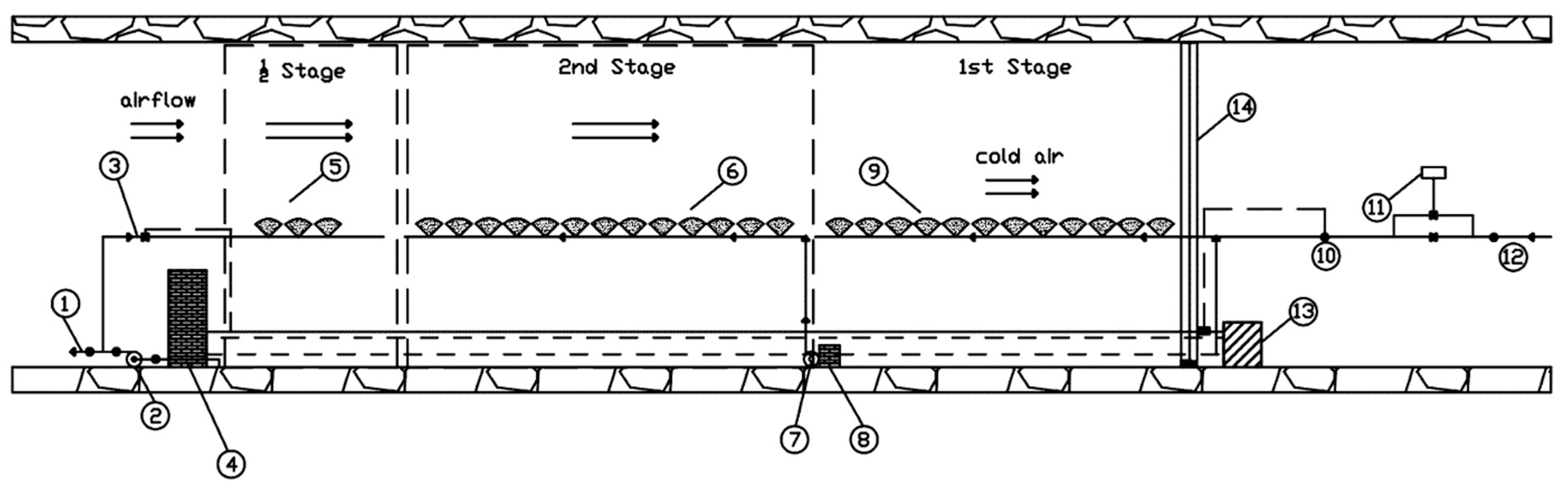
1.1.6. Large-Scale Spray Cooling: Bulk-Air-Coolers (BACs)
Bulk air coolers (BAC) are typically most preferred large-scale cooling systems in mining. As the name may imply, bulk air coolers are deemed as direct heat exchangers and can be employed in various scales. BACs are either horizontal or vertical chambers equipped with chilled water spraying nozzle systems. Heat exchange occurs between water spray and air within these chambers. The continuous stream (air) is simply forced to flow between the walls of the BAC and get sprayed over with chilled water. For design purposes it should be noted that the horizontal counter-flow industrial BAC units may come up with more than one stages depending on the required cooling duty. These stages simply represent compartmentalized cooling chambers and their number is usually determined depending on the factor of merit of the selected design [
18]. Note that the merit factor indicates the performance of the counter-flow direct heat exchangers and it ranges between 0 and 1 [
18]. Typical industrial merit factors range between 0.3 and 0.8 [
18].
Figure 2 is reprinted from Bluhm’s and Whillier’s work showing different components of a typical horizontal spray chamber with 2.5 stages [
25].
2. Methodology
At this point, it is important to remark that due to confidentiality reasons all the information provided in the following sections of this paper is presented anonymously.
Essentially, to better understand the feasibility of the proposed deep lake cooling project, it was crucial to understand mine’s cooling demand over the cooling days of the year. Having modeled the critical temperature and airflow model in a computer aided environment, the cooling feasibility of the lake was investigated to see if the coolth extracted would be enough for cooling sustainably over the life-of-mine (LoM). This study highly focuses on the amount of the water needed to be used for cooling purposes.
2.1. Theoretical Background
In the light of modern mine cooling strategies and conventional mine refrigeration applications it is observable that; conventional mine cooling strategies are mostly put forward based on the principles put together in McPherson’s book, Chapter 18 [
18]. Based on the theoretical perspectives stated here [
18] a cooling strategy for the given mine was developed.
To summarize the mathematical relation used in designing the cooling systems proposed here, the following thermodynamic relationship was used as shown in Equation (1):
where
and
stand for the mass flow rates of air and water,
and
represent outlet and inlet enthalpy for mine air,
and
is used for water inlet and outlet temperatures and
stands for specific heat for water flow, respectively [
18].
Moving from Equation (1) one can determine ideal conditions where
equals to
being the inlet air wet-bulb temperature and
equals to
being outlet air wet-bulb temperature. Where the ratio in between these gradients yield the non-dimensional ratio called water efficiency,
ηw [
18]:
Additionally, similar relationship can be constructed on air side by using the enthalpies as well. Therefore, one can say:
where the ratio of these two non-dimensional parameters yield to another non-dimensional ratio named as tower capacity factor called,
R [
18] as shown below:
Accordingly, McPherson [
18] defines effectiveness,
E of the cooling plant as a logical statement attaching it to these efficiency factors as shown in conditions below:
As cited in McPherson in his book [
18], then another logical factor,
R* was being introduced by Whillier (as cited in McPherson [
18]) allowing to flip the ratio
R for the conditions where
R overpasses the unity as shown below:
Then he refers to Whillier’s attempt to fit this relationship to a curve (as cited in McPherson [
18]) yielding the effectiveness as:
where
F stands for the factor of merit of the cooling design and ranges between 0 and 1. The factor of merit values for this particular design project was based on the industry based, empirical values predicted by Whillier and Bluhm (as cited in McPherson [
18]) and mentioned further in the following parts of the present study.
Finally, McPherson mentions the number of staging,
N in a BAC system with the following relationship stated in Equation (8):
2.2. Cooling Demand of the Mine
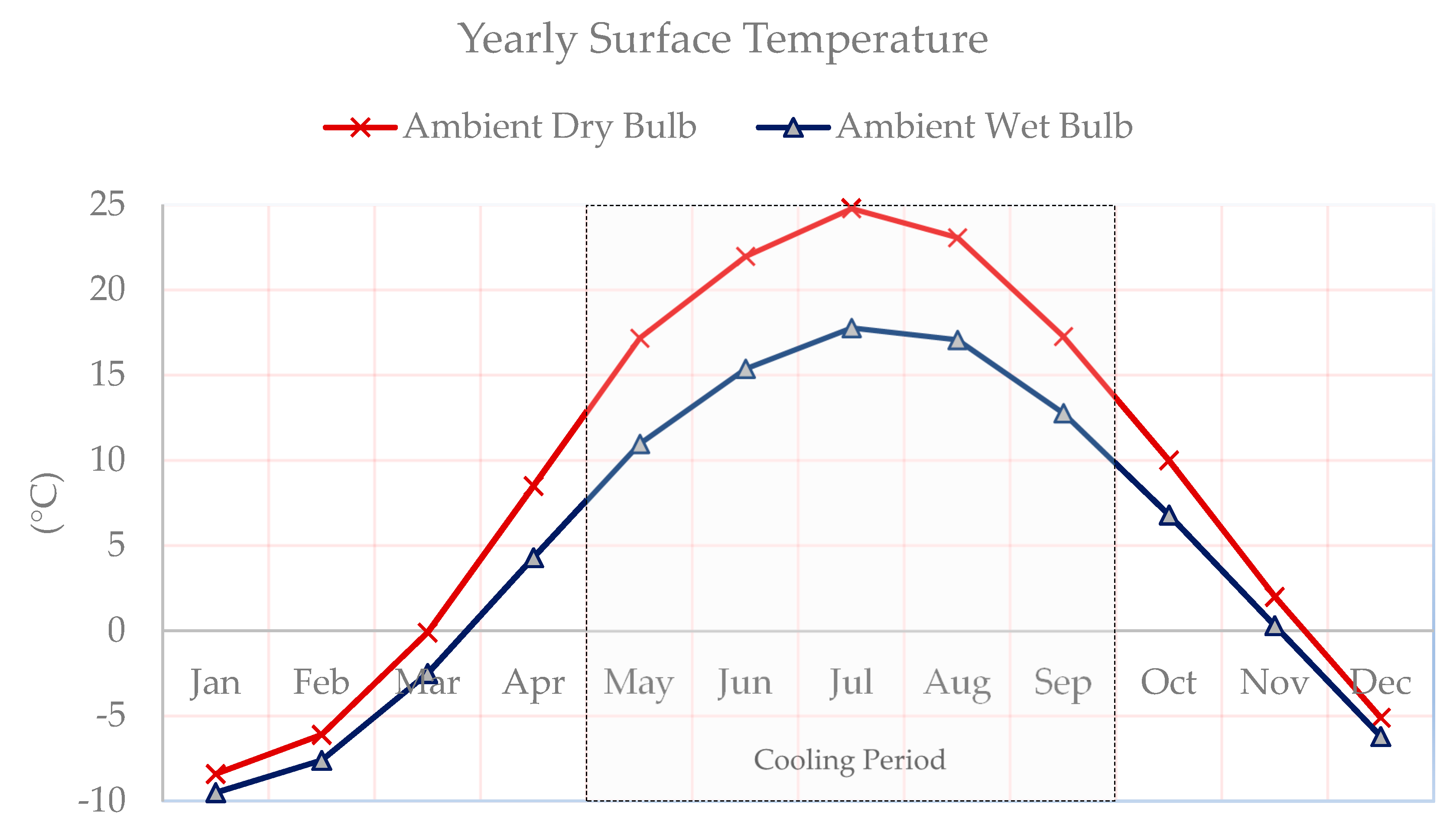
The subsurface mining operation presented here as a case study is located Canada. As the best approximation to the field data, closest airport, year-round temperature data was retrieved and printed in
Figure 3. As it can be seen in
Figure 3, the mine site reaches peak-summer season in July and the mine requires full capacity underground cooling between May and September to sustain the temperatures stated in
Table 2.
It is also important to note that, the mine presented here will be using a fully-battery-driven mine fleet to conduct its mining operations. Regarding mine ventilation system was designed based on a ‘push-pull vent system’ mainly relying on the pulling fans installed at the exhaust shaft. Considering, the LoM production schedule and introduced mine machinery utilization, mine air simulations dictated requirement of 1000 kcfm of fresh air provision for safe mining. Some of the critical information regarding the selected mine is presented in
Table 3.
Note that there is also the thermal impact caused by the auto-compression of the sinking air to be listed as another crucial source of heat for deep mining operations such as the one presented here. This phenomenon occurs due to molecular compression of the shaft air due to gravitational force during its journey to the mine network. The compression in the mine air system creates a high amount of temperature rises for large depths. The mere impact of the mine air auto-compression based on mine production scheme will later be touched on.
Due to high effectiveness of direct cooling systems and financial performance of open-loop water delivery process (i.e., low piping cost and low pressure on the line due to less piping), an open-loop, spray cooling-based BAC system is selected as it is the most appropriate cooling scenario for this case study. This process will be thoroughly investigated in the forthcoming sections.
Here, it is worth mentioning that the mine LoM (life-of-mine) plan for the introduced mine revealed that the operation is expected to reach its maximum production capacity during the 15th year of the mine life allowing all the equipment and machinery on duty with full performance. Therefore, a 15th year and corresponding production schedule is considered as the ‘worst-case scenario’ and selected as the benchmark year for the mine air network simulations.
Figure 4 depicts the mine LoM production scheduling results for the overall mine life.
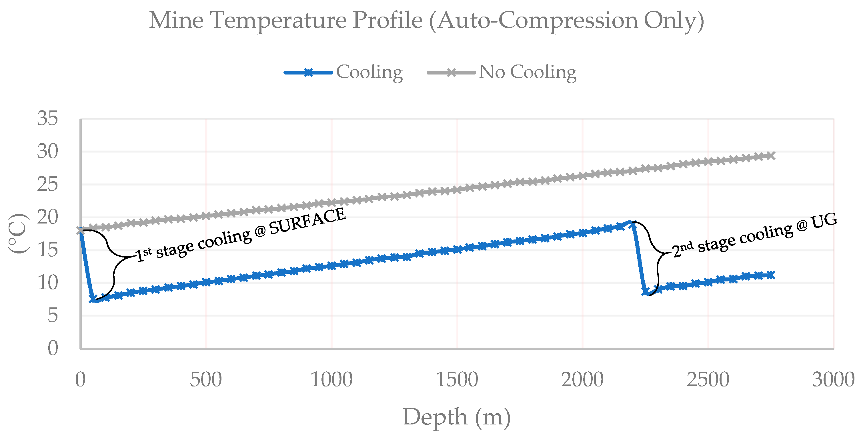
Rewinding to the mine air auto-compression,
Figure 5 shows the temperature profile of the mine with no cooling for the thermal load during period that the ‘worst-case scenario’ is attained as introduced above. At this stage all the main extraction points are fully developed, and a continuous production is expected. Additionally, to ensure the necessary cooling, an iterative process is applied to make sure that no temperature along the critical loop exceeds 27 °C wet-bulb temperature even with maximum performance. Based on the results of the mine air network simulations and several techno-economic advantages a design with two-stage (i.e., surface plant and u/g plant) cooling is decided. The depth of each cooling plant is marked on
Figure 5.
Note that, the following chart shows the temperature change due to auto-compression only. Additional heat load of 7.4 MW (see
Table 3) caused by mobile equipment, mine machinery and ore production are not included as they are mostly mobile in the mine network. Even so, it is observable that the auto-compression itself is enough to heat the mine air up to off regulation limits at lower levels of the mine.
2.3. Lake Water Baseline Study
As introduced, based on the flow characteristics and seasonal temperature changes, lakes tend to form a thermal stratification within its water body [
14] allowing different temperatures at different depths.
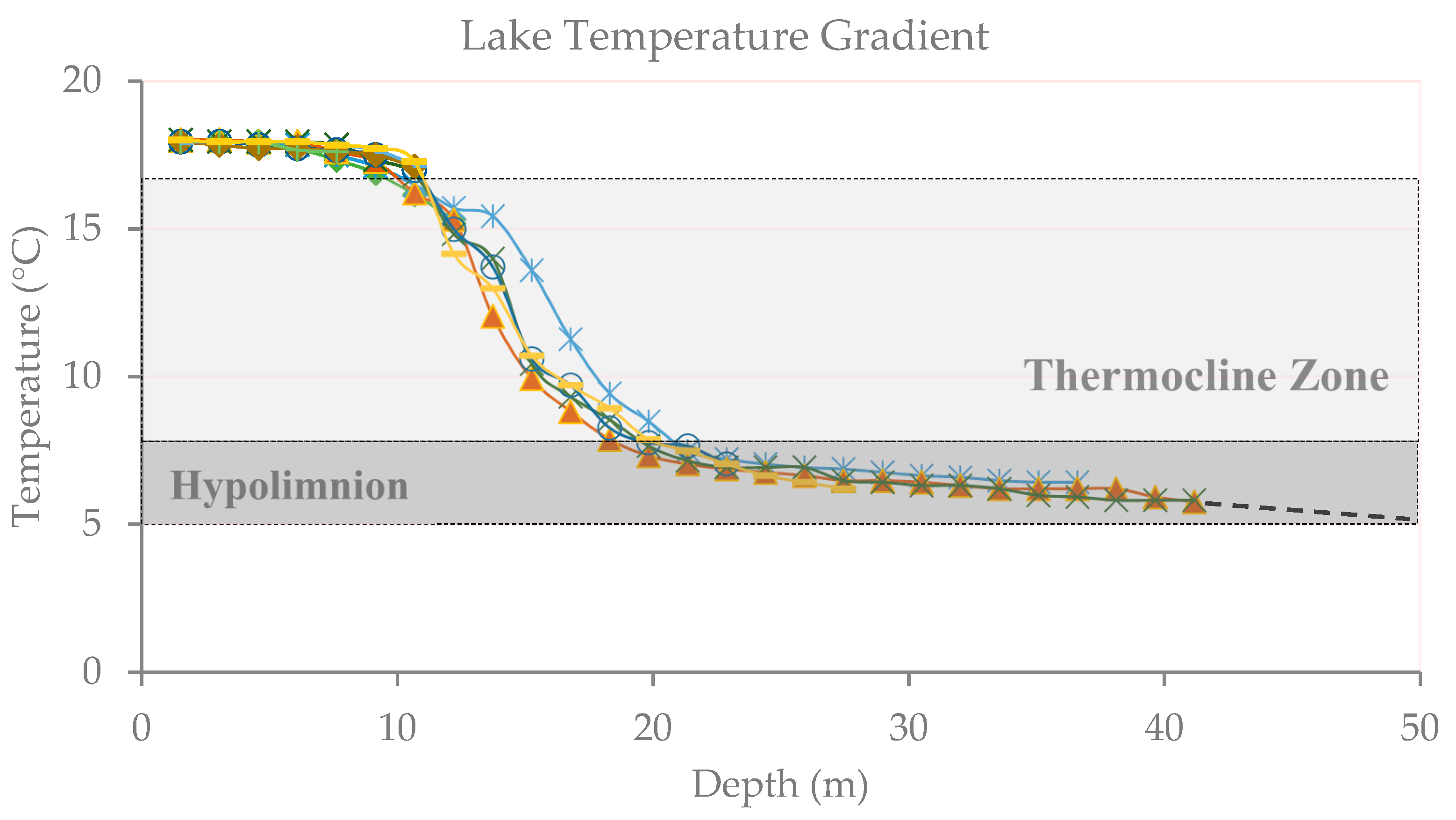
Figure 6 shows the temperature values obtained from the nearby lake that is considered to cool the mine for this case. For this example, it is clear to see that after the thermocline zone, hypolimnion allows extraction of ~5 °C of water at around 45–50 m depths.
Figure 6 shows temperature measurement holes and their depth versus temperature response. In
Figure 6 each curve with different color represents a different hole showing data collected at various depths highlighted by the markers on the curves.
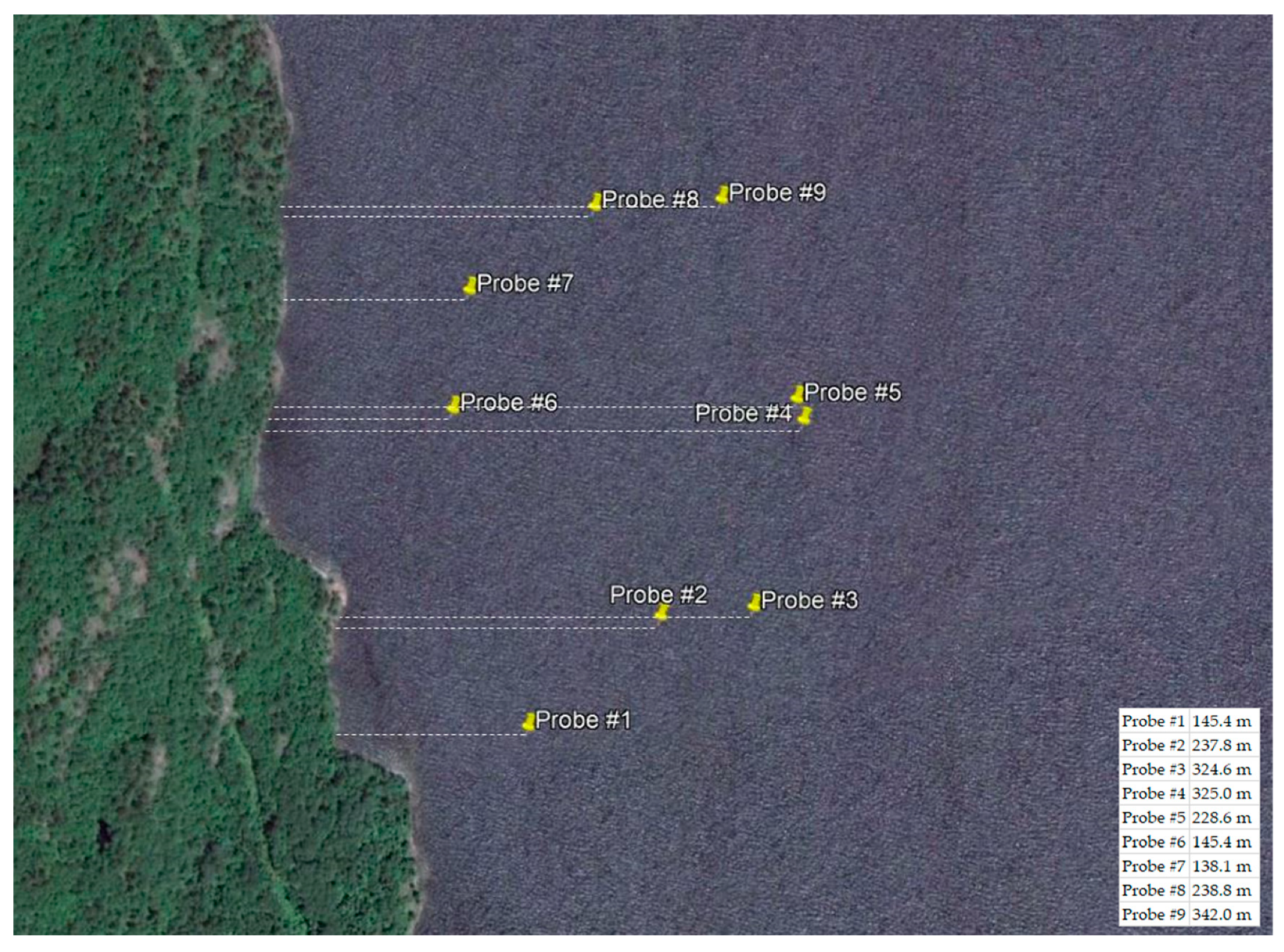
Data collection from the given lake was done at nine different measurement points with special instruments allowing minimum deviation during probe sinking. Measurement probes used during the data collection process were able to collect pressure and temperature data. All the measurements are taken during various times of the year mostly ranging from the peak summer time to mid-fall season of the region.
Statistical summary of the data collected during different times of the year has shown that the convectional movement at the upper lake and shifts in the thermocline zone will not affect the average hypolimnion temperature year-round validating the statements put forward in references [
15,
16]. Geospatial location of the probes and relative distances of the holes from the shoreline is shown with a Google Earth
® image on
Figure 7.
Finally, it is important to highlight that the lake introduced here has approximately 190 km2 of a surface area with maximum depth of 142 m at its deepest point yielding roughly 21 million m3 of chilled water below the hypolimnion level. This allows the lake to be a fundamentally large cooling source considering the cooling demand of the mine.
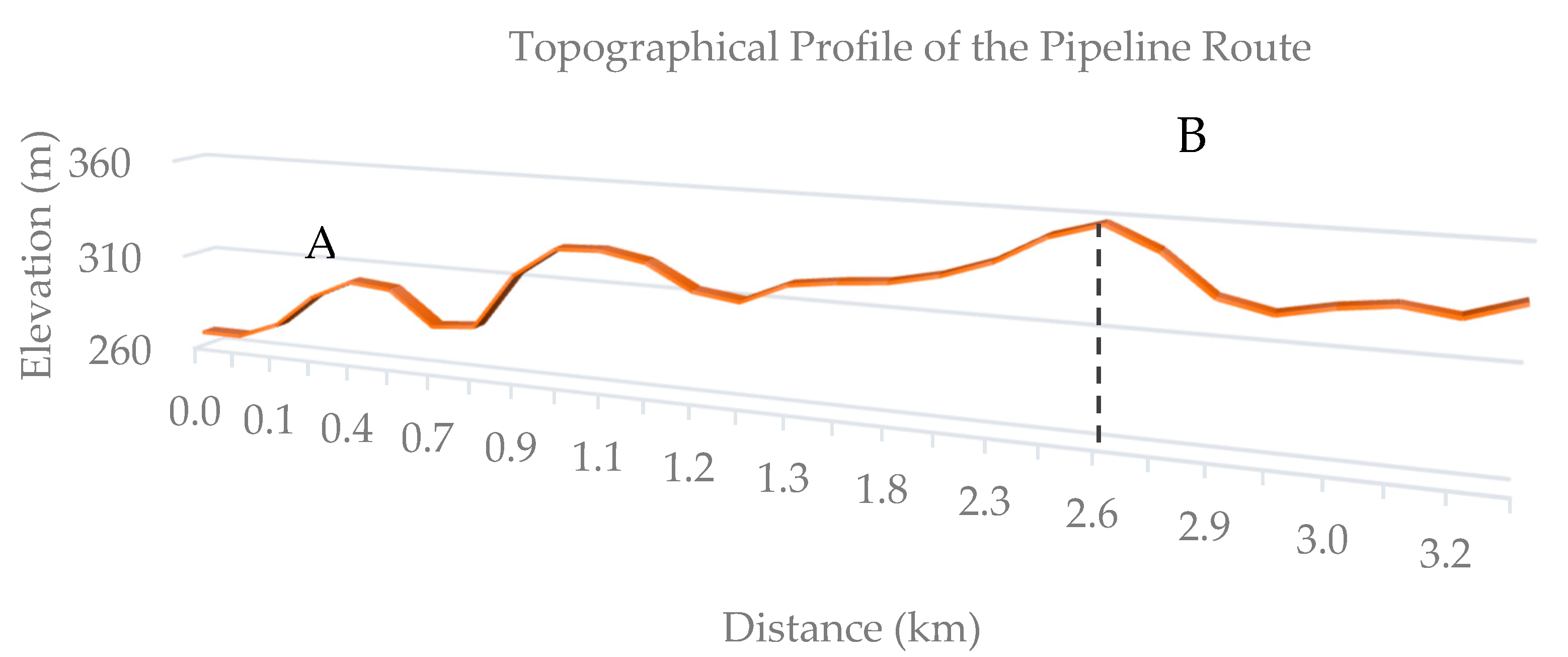
On the other hand,
Figure 8 is the reconstruction of the tentative profile of the pipeline pathway with data obtained from Google Earth
®. The dashed line shows the point where maximum elevation of the pipeline route is attained. Point ‘A’ locates the lake water entrance elevation and point ‘B’ locates the mine site. Overall route distance is measured as ~3.4 km. Please note that this information is used during the prefeasibility stage and the pipeline pathway is tentative to change based on the availability of the land along the route.
Again, due to confidentiality reasons, locational information of the lake and the pipeline pathway information is withheld from this section. For better performance during peak seasons, mineral wool insulation with insulative painting is considered for the pipeline to prevent heat gain/loss issues. The thermodynamic study conducted to ensure the pipeline performance during operation, has revealed that a ±0.5 °C temperature gain/loss is expected for extreme summer/winter conditions including friction and ambient air convection. This study is still ongoing and data from new holes are being collected during finalization of this work.
2.4. Cooling Design and Sensitivity Studies
As briefly mentioned before, based on the performance results acquired from mine air simulations, it is decided to implement a two-phase cooling as it is the most effective scenario due to financial and operational reasons. Note that, two-stage cooling in here refers to two separate cooling plants located at two distinct locations on site and not to be confused with staging inside the BAC unit. Note that, first BAC is designed to be located at the surface (also referred as surface plan), next to the shaft intake and the other relatively smaller size plant is located at the shaft bottom (at –2300 m) as the secondary BAC (also referred as underground plant or u/g plant).
The reasoning for why a secondary plant is designed to be deployed at the shaft bottom can be attached to the thermal impact of auto-compression. In other words, as the auto-compression would take place under any circumstance, rather than increasing the capacity of the surface plant significantly, the cooling duty is divided into two plants to minimize the impact of auto-compression along the way after the surface BAC. Note that, surface plant is designed to operate only for five months (also referred as cooling months between May-Sept.) of the year whereas the underground BAC is designed to work all-year-round.
Table 4 summarizes optimized results of the air conditioning calculations based on [
18]. Note that these results depend on empirical studies and used as the input to the mine air network simulation. With this input data, simulation has shown that maximum temperatures are attained at some branches of lowest mine workings with 25 °C WBT staying within the regulations even during the hottest season with worst-case operational conditions (see
Figure 3 and
Figure 4).
2.5. Surface Plant Design
Based on pipeline water transfer calculations based on peak summer conditions, it is assumed to have ~6 °C chilled lake water at the mine site. However due to immaturity of the pipeline insulation framework, chilled water temperature sensitivity is also studied and presented in the following section.
Table 5 summarizes surface plant cooling characteristics.
For surface plant, a three-stage BAC unit is selected. Note that, according to empirical data given by McPherson [
18] for three-stage horizontal BAC units, merit factors should be expected between 0.65–0.75. For this study, 0.7 is selected as merit factor.
Table 5 below summarizes the design parameters calculated for the surface BAC design.
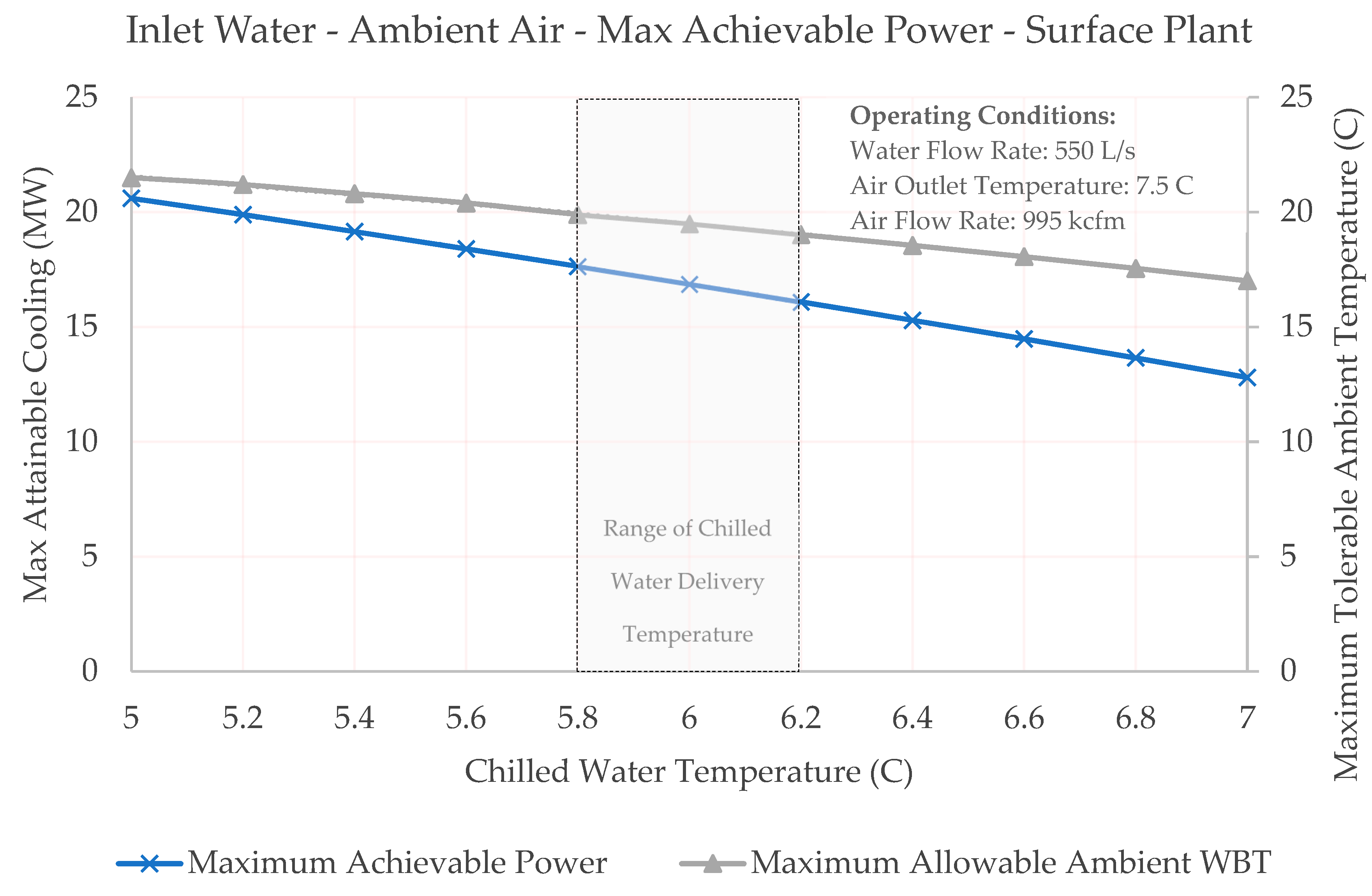
Figure 9 shows the maximum cooling conditions to achieve 7.5 °C output air temperature with 1000 kcfm with 530 L/s flow rate. Please note that, input conditions are fixed except the chilled water inlet temperature to observe the impact of changing water temperature. Any working point below the curves are attainable with the proposed lake cooling system and curves represented here are maximum allowable points to keep fixed parameters unchanged. According to the following figure, maximum achievable cooling power with 6 °C intake water at 530 L/s flow rate happens when 19 °C ambient WBT is reached with 16.1 MW. However, maximum attainable cooling power drops significantly with increasing inlet water temperature.
Note that, for this type of cooling system, the evaporation is usually negligible [
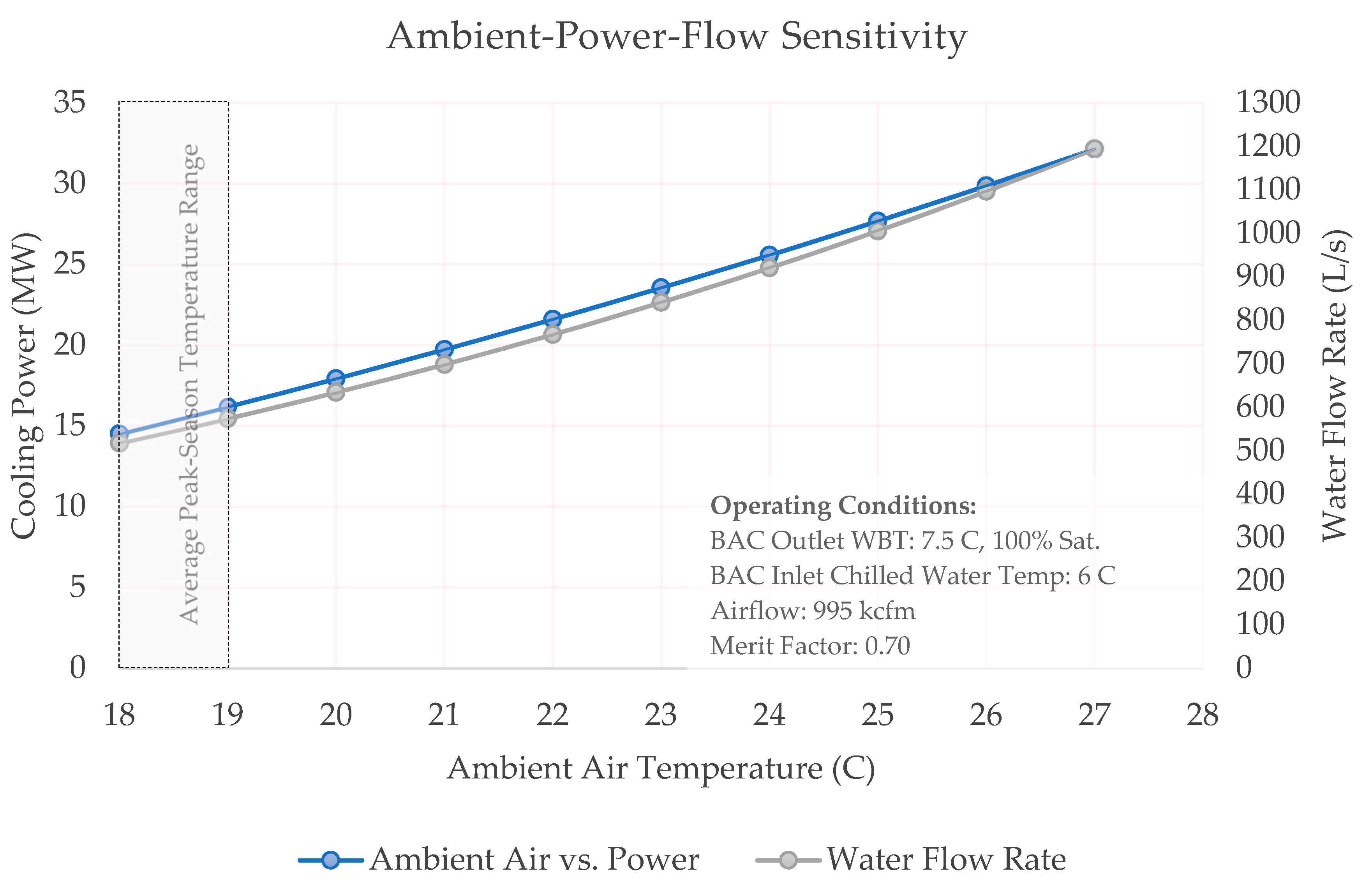
18]. Nevertheless, some make up water should be expected within 2–3% of overall spray system capacity. Therefore, surface cooling plant is designed for a capacity of 550 L/s including 20 L/s contingency for make-up water. The chart provided in
Figure 10, shows a more detailed ambient (inlet) air temperature sensitivity of the surface plant. Please note that in this chart all operational parameters are fixed and only the impact of changing ambient air temperature is shown. Seemingly, the dashed-box is representing the proposed cooling system operating range.
2.6. Underground Plant Design
Similarly, underground cooling plant was also designed based on 0.7 merit factor with three-stages. Note that, this cooling plant will be required before the maximum production year is started due to additional cooling duty required by the lowest level of operation. Therefore, the design introduced here will be deployed during the 10th year of the mine life. This information might be useful to better understand the financials of the project later.
Table 6 lists a brief summary of operating conditions for the u/g air cooling plant.
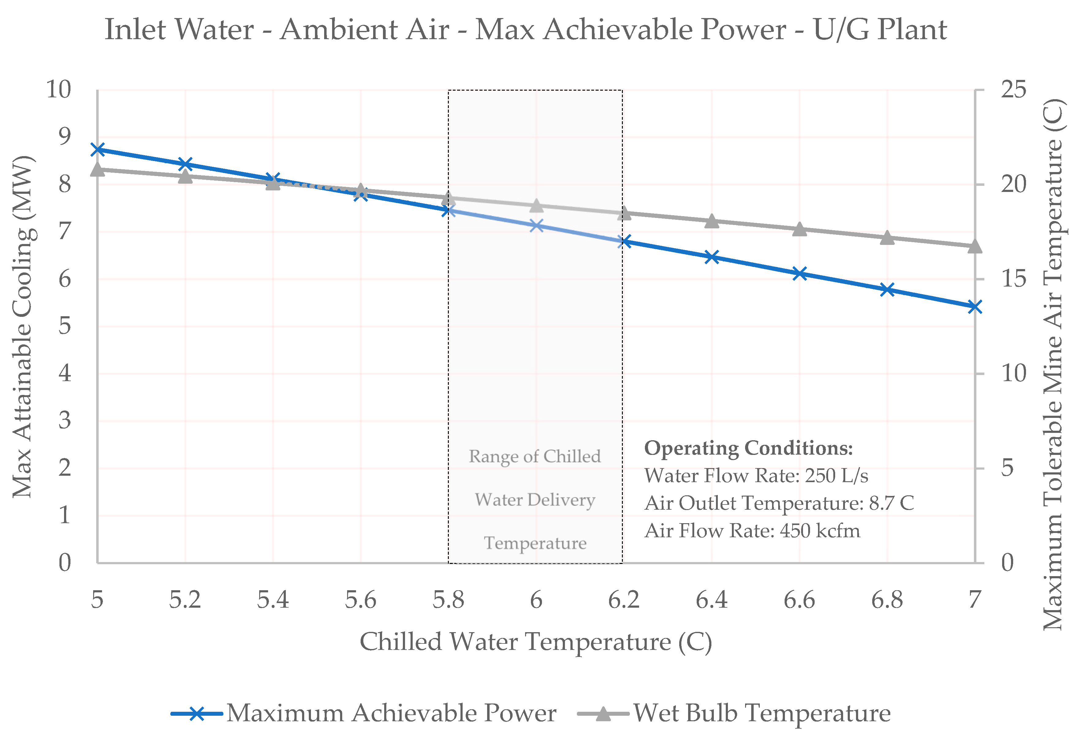
Again, for underground cooling plant, maximum achievable points are showing that the warmer the chilled water intake lesser the cooling power delivery and less capability for cooling the ambient air. Suggested operating points are also shown on the chart presented in
Figure 11. Like the surface cooling plant case, it is shown here that any increment in the inlet chilled water temperature negatively affects the cooling performance with a parabolic relation.
Figure 11 also shows that there is a similar relationship between inlet water temperature and maximum deliverable power.
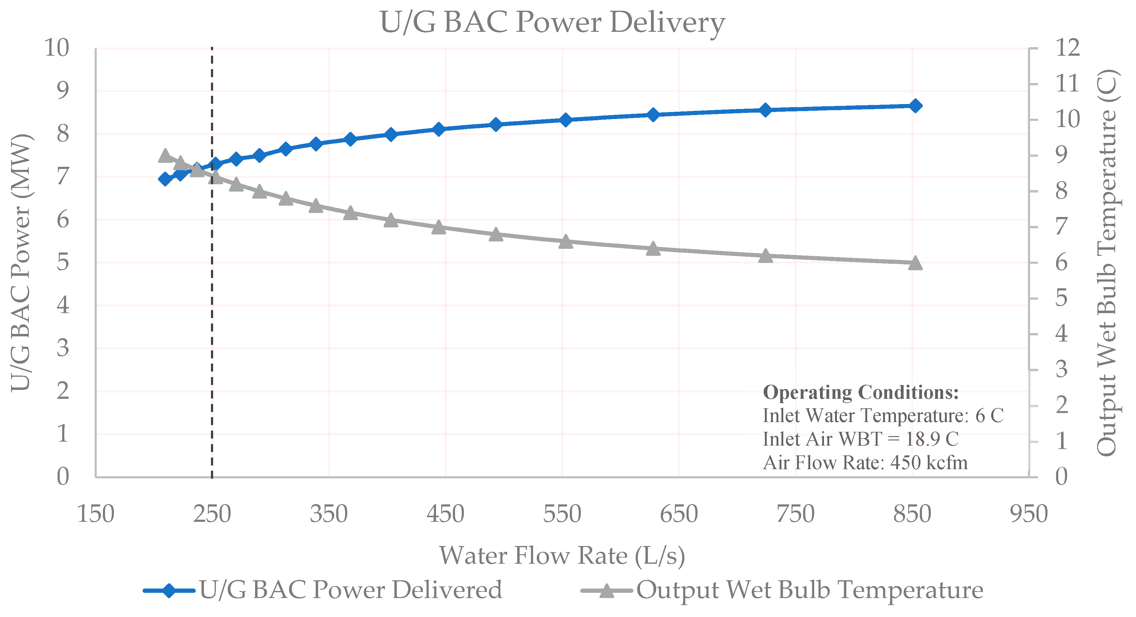
Due to a lack of a complete mine model only the critical ventilation path is used to develop the cooling design of the U/G plant. Therefore, to prevent any unforeseen circumstance in the fully developed mine scenario, which includes many other properties of a working mine, a sensitivity analysis concerning power delivery and output ambient air temperature of underground plant is also studied and presented in
Figure 12.
The chart shows the suggested operational point for the u/g plant design with a dashed line. It is also shown that colder output temperatures can be reached with more water delivery. However, with an operational perspective it should be noted that piping and pumping facilities, hydraulic recovery units and shaft clearance should be enough at least with 20% of safety factor. This problem can be mitigated by employment of localized BAC units for spot-on cooling. These hydropower-driven spot coolers are usually dependent on the similar restrictions with stationary ones in terms of intake water and ambient air conditions [
26]. However, they usually provide significantly less cooling power with 100–500 kW range and they are only designed for local cooling [
26].
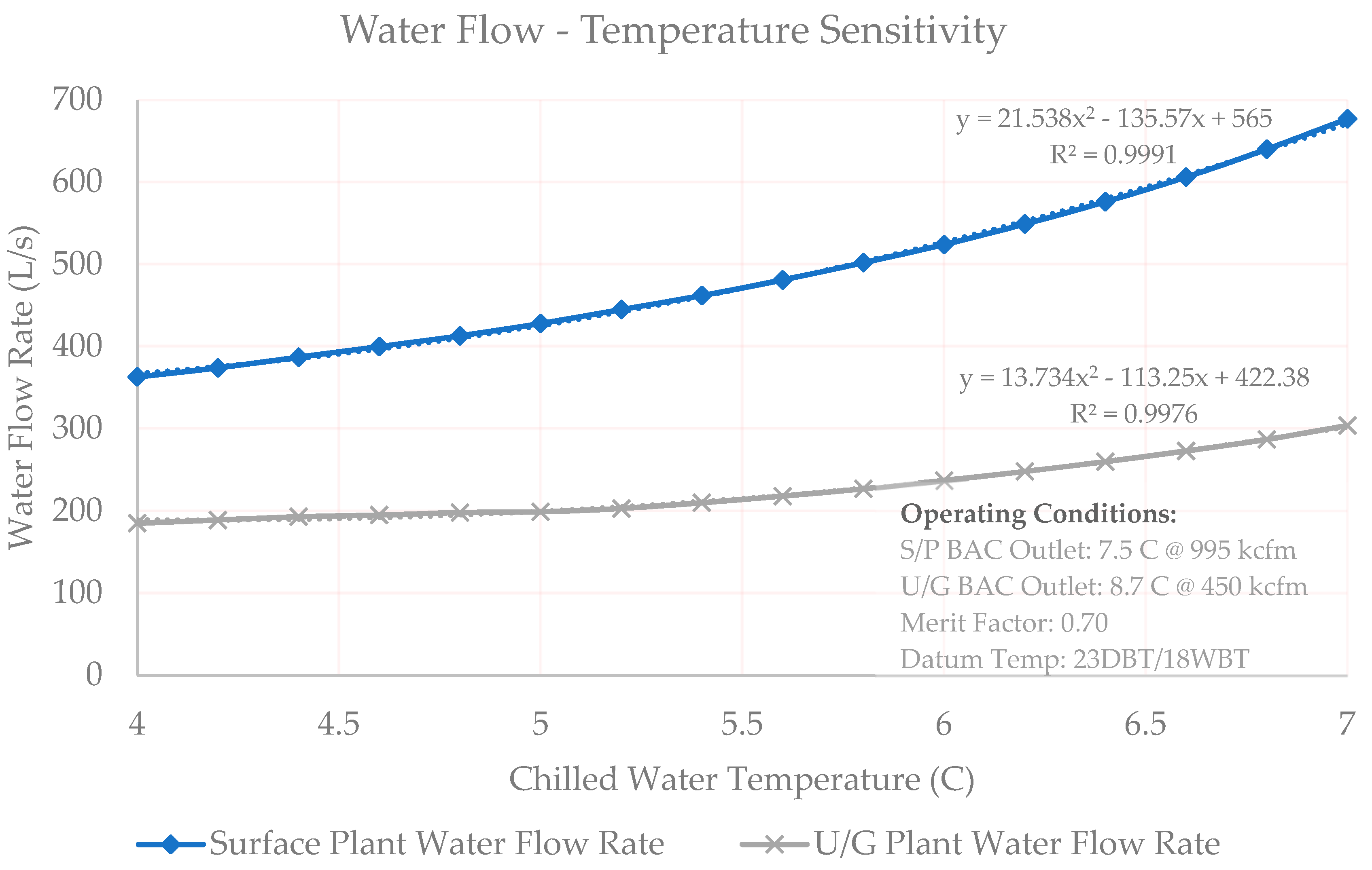
As mentioned before, pipeline and pump station designs are still ongoing and new data is still being collected. Therefore, a sensitivity study showing the water required at different chilled water temperatures is also studied and shown in
Figure 13 to find the mathematical relationship between water temperature and the flow rate needed.
2.7. Hydraulic Recovery System
In this project a hydraulic recovery plan was also developed. Based on the mine plan, three levels on the intake shaft is selected for Pelton turbine installation. Hydraulic recovery system plays a very important role on lowering the pipeline pressure by staging the flow and keeping the temperature gain at minimum while saving from energy. Related financial scenarios and associated savings are also studied:
- -
U/G cooling without hydraulic recovery system,
- -
U/G cooling with hydraulic recovery system coupled to pumps, and
- -
U/G cooling with hydraulic recovery system coupled to generators.
Details of this work are beyond the reach of this study. However, for the interested audience, more details about the hydraulic recovery section can be found and retrieved from [
27].
3. Results and Discussion
The preliminary cooling design study has shown that significant CAPEX savings can be made by deployment of deep-lake cooling system instead of conventional refrigeration, for this case. However, it is worth to note that, lake cooling system may not attend extremely cold air temperatures as it is not mechanized like conventional system and relies on natural resource availability. This is completely intrinsic for lake cooling systems as the lake hypolimnion water temperature is a limiting factor. Therefore, it should be stated that cooling demand and required plant output conditions should be well understood during the techno-economic assessment of any lake cooling project.
Note that all financial results listed here are in today’s values and they are not subjected to any discount or inflation factors.
The third-party consulting firms involved in the cooling design of the mine, offered conventional refrigeration systems for both surface and underground cooling plants introduced before. Operational characteristics of the conventional system suggested by consulting firms are comparably similar to the lake cooling system proposed here.
The refrigeration units and plantroom construction are usually considered as the most capital-intensive items for the conventional design. In this case, standalone cost of suggested refrigeration units and plantroom for both plants constitute ~50% of the overall capital investment of CAD
$52.4M (Canadian Dollar) (i.e., CAD
$21.3M for the surface plant and CAD
$31.2M for the underground plant) which includes other expenditures like power line distribution, instrumentation, and BAC construction. In fact, not needing a refrigeration system can be considered as the largest CAPEX-related advantage of a deep-lake cooling system, hence they simply discard the most expensive machinery and associated costs from the investment. Due to confidentiality of the work, financial details of the proposed conventional refrigeration are not shown here. On the other hand, deep-lake cooling cost estimations can be referred from
Table 7. Please be reminded that the underground plant cost will be considered after the 10th year of production.
Here, it shall be highlighted that given the average lake water temperature data collected at different times of the year, thermodynamic studies representing the year-round water delivery at peak times and the mine ventilation and air conditioning study conducted based on the “worst-case operational scenario” CAPEX size presented in
Table 7 represents the theoretically highest possible capital investment including all the estimated contingencies.
Here, it is important to remark that the OPEX (operational expenditure) of the lake cooling system is very tentative to changes in water delivery temperature, water flow rate, location of hydraulic recovery units, hydraulic recovery type (i.e., uncoupled, pump coupled, or generator coupled), and so on. There is also another study investigating the potentiality of re-utilization of the underground BAC water as a thermal source during the winter time for mine air-preconditioning. All these circumstances yield different OPEX scenarios and due to space limitations, they are not presented here.
4. Conclusions
Industrial size ambient air-cooling applications are usually capital-intensive projects as they rely on expensive machinery and plantrooms. Natural source-based cooling could be a very elegant solution to this problem once it is thoroughly understood. In this perspective, a deep, cold lake in the proximity of an ultra-deep Canadian underground mine was selected to comply with the cooling needs of the proposed mining operation to identify the possibility of lake cooling systems for a real-life application. Performance of the lake cooling was presented with several sensitivity analyses signifying the importance of vital parameters such as water delivery temperature and flow rates.
Results of this study has shown that, deep lake cooling systems can attain similar cooling performances compared to conventional design with a cleaner and more profitable outlook. In fact, this example has shown that, employing a lake cooling system could slash capital expenditures of a deep mine HVAC system with a size of CAD $11.8 M CAPEX saving. These savings are mainly associated with the fact that a lake cooling system does not require large-scale compression/refrigeration machinery and a large plantroom installation forming more than ~50% of the overall system CAPEX of conventional systems.
Author Contributions
Conceptualization, F.H., S.A.G.-M., A.P.S. and A.F.K.; Methodology, S.A.G.-M. and A.F.K.; Software, A.F.K.; Validation, S.A.G.-M. and A.F.K.; Formal Analysis, S.A.G.-M. and A.P.S. and F.H.; Investigation, F.H., S.A.G.-M. and A.P.S.; Resources, F.H., A.P.S. and S.A.G.-M.; Data Curation, A.F.K. and S.A.G.-M.; Writing-Original Draft Preparation, A.F.K.; Writing-Review & Editing, A.F.K. and S.A.G.-M.; Visualization, A.F.K.; Supervision, F.H., A.P.S. and S.A.G.-M.; Project Administration, F.H. and S.P.S.; Funding Acquisition, A.P.S.
Funding
This research was funded by [Ultra-deep Mining Network] grant number [UDMN#2-005 – Phase 2] and The APC was waived ].
Acknowledgments
We would like to say many thanks to our anonymous industrial partners and their valuable personnel for helping and guiding us through this project. We are also very thankful to the Ultra Deep Mining Network (UDMN) for their valuable contributions to our research environment. Without their support this study would not be realized.
Conflicts of Interest
The authors declare no conflict of interest. The funders had no role in the design of the study; in the collection, analyses, or interpretation of data; in the writing of the manuscript, and in the decision to publish the results.
References
- Vergne, J.D.L. Hardrock Miner’s Handbook; Stantec: Edmonton, AB, Canada, 2000. [Google Scholar]
- Marshall, B. Facts and Figures of the Canadian Mining Industry; The Mining Assoc. of Canada: Ottawa, ON, Canada, 2016. [Google Scholar]
- Ballantyne, G.R.; Powell, M.S. Benchmarking comminution energy consumption for the processing of copper and gold ores. Miner. Eng. 2014, 65, 109–114. [Google Scholar] [CrossRef]
- Thollander, P.; Ottosson, M. Energy management practices in Swedish energy-intensive industries. J. Clean. Prod. 2010, 18, 1125–1133. [Google Scholar] [CrossRef]
- Newman, L.; Herbert, Y. The use of deep water cooling systems: Two Canadian examples. Renew. Energy 2009, 34, 727–730. [Google Scholar] [CrossRef]
- Ghoreishi-Madiseh, S.A.; Sasmito, A.P.; Hassani, F.P.; Amiri, L. Performance evaluation of large scale rock-pit seasonal thermal energy storage for application in underground mine ventilation. Appl. Energy 2017, 185, 1940–1947. [Google Scholar] [CrossRef]
- Ghoreishi-Madiseh, S.A.; Sasmito, A.P.; Hassani, F.P.; Amiri, L. Heat Transfer Analysis of Large Scale Seasonal Thermal Energy Storage for Underground Mine Ventilation. Energy Procedia 2015, 75, 2093–2098. [Google Scholar] [CrossRef]
- BCS Incorporated. Mining Industry Energy Bandwidth Study; BCS Incorporated: Laurel, MD, USA, 2007. [Google Scholar]
- Stebbins, S.A. Cost Mine: Mining Cost Service; InfoMine: Fredericton, NB, Canada, 2007. [Google Scholar]
- Rothstein, D.A.; Manning, C.E. Geothermal gradients in continental magmatic arcs; constraints from the eastern Peninsular Ranges Batholith, Baja California, Mexico. Geol. Soc. Am. Spec. Pap. 2003, 374, 337. [Google Scholar] [CrossRef]
- He, M. Application of HEMS cooling technology in deep mine heat hazard control. Min. Sci. Technol. (China) 2009, 19, 269–275. [Google Scholar] [CrossRef]
- Kenny, G.P.; Vierula, M.; Maté, J.; Beaulieu, F.; Hardcastle, S.G.; Reardon, F. A Field Evaluation of the Physiological Demands of Miners in Canada’s Deep Mechanized Mines. J. Occup. Environ. Hyg. 2012, 9, 491–501. [Google Scholar] [CrossRef] [PubMed]
- ASHRAE. 2011 ASHRAE Handbook; ASHRAE: Atlanta, GA, USA, 2011. [Google Scholar]
- Marietta College, Department of Biology and Environmental Science. Lakes and Other Aquatic Habitats; n.d.; Marietta, OH, USA.
- David Malcolm Livingstone. An example of the simultaneous occurrence of climate-driven “sawtooth” Deep-Water Warming/Cooling Episodes in Several Swiss Lakes. 1997. Available online: http://data.theeuropeanlibrary.org/BibliographicResource/1000051415459 (accessed on 27 February 2019).
- Peirce, L.B. Reservoir temperatures in north-central Alabama. Ala. Geol. Sur. Bull. 1964, 82, 108. [Google Scholar]
- Enwave Corp. Enwave Toronto; Enwave Corp.: Delta, BC, Canada, 2018. [Google Scholar]
- McPherson, M.J. Subsurface Ventilation and Environmental Engineering; Mine Ventilation Services, Incorporated: Montreal, QC, Canada, 1993; pp. 651–738. [Google Scholar]
- Lin, L.; Ponnappan, R. Heat transfer characteristics of spray cooling in a closed loop. Int. J. Heat Mass Transf. 2003, 46, 3737–3746. [Google Scholar] [CrossRef]
- Kim, J. Spray cooling heat transfer: The state of the art. Int. J. Heat Fluid Flow 2007, 28, 753–767. [Google Scholar] [CrossRef]
- Alkhedhair, A.; Gurgenci, H.; Jahn, I.; Guan, Z.; He, S. Numerical simulation of water spray for pre-cooling of inlet air in natural draft dry cooling towers. Appl. Therm. Eng. 2013, 61, 416–424. [Google Scholar] [CrossRef]
- Sureshkumar, R.; Dhar, P.L.; Kale, S.R. Effects of spray modeling on heat and mass transfer in air–water spray systems in parallel flow. Int. Commun. Heat Mass Transf. 2007, 34, 878–886. [Google Scholar] [CrossRef]
- Sureshkumar, R.; Kale, S.R.; Dhar, P.L. Heat and mass transfer processes between a water spray and ambient air—I. Experimental data. Appl. Therm. Eng. 2008, 28, 349–360. [Google Scholar] [CrossRef]
- Wang, S.K. Handbook of Air Conditioning and Refrigeration; McGraw-Hill: New York, NY, USA, 2001. [Google Scholar]
- Bluhm, S.J.; Whillier, A. The design of spray chambers for bulk cooling of the air in mines. J. S. Afr. Inst. Min. Metall. 1978, 79, 1–9. [Google Scholar]
- du Plessis, J.J.L.; Scott, D.; Moorcroft, H.E.S. Modern cooling strategies for ultra-deep hydropower mines. J. Mine Vent. Soc. S. Afr. 2006, pp. 94–99. Available online: https://repository.up.ac.za/bitstream/handle/2263/59443/DuPlessis_Modern_2006.pdf?sequence=1&isAllowed=y (accessed on 27 February 2019).
- Templeton, J.; Amiri, L.; Kuyuk, A.; Ghoreishi-Madiseh, S. A and Sasmito, A.P. Evaluation of the Hydraulic Recovery Potential in a Lake-Sourced Underground Mine Refrigeration System; Springer: Berlin, Germany, 2018. [Google Scholar]
Figure 1.
Deep lake water utilization scheme (not to scale).
Figure 1.
Deep lake water utilization scheme (not to scale).
Figure 2.
A typical horizontal BAC (modified and reprinted from) [
25]. 1—Return pipeline, 2—pump, 3—modulating valve, 4—dam wall, 5—1/2 stage final sprays, 6—secondary sprays, 7—submerged pumps, 8—lower dam walls, 9—primary sprays, 10—float valve, 11—temperature control valve, 12—cold water supply valve, 13—dam wall, 14—mist eliminating plates.
Figure 3.
Annual temperature profile of the mine site location.
Figure 3.
Annual temperature profile of the mine site location.
Figure 4.
Mine overall production schedule.
Figure 4.
Mine overall production schedule.
Figure 5.
Impact of mine auto-compression.
Figure 5.
Impact of mine auto-compression.
Figure 6.
Lake temperature profile.
Figure 6.
Lake temperature profile.
Figure 7.
Satellite image showing probe locations and distances from the shoreline.
Figure 7.
Satellite image showing probe locations and distances from the shoreline.
Figure 8.
Potential pipeline path showing the topographical cross-section.
Figure 8.
Potential pipeline path showing the topographical cross-section.
Figure 9.
Surface plant design and operating ranges showing maximum attainable cooling power at different surface ambient temperatures.
Figure 9.
Surface plant design and operating ranges showing maximum attainable cooling power at different surface ambient temperatures.
Figure 10.
Surface plant design cooling sensitivity and required water delivery curves based on changing ambient air temperature (i.e., cooling power (blue), left, and flow rate (grey), right).
Figure 10.
Surface plant design cooling sensitivity and required water delivery curves based on changing ambient air temperature (i.e., cooling power (blue), left, and flow rate (grey), right).
Figure 11.
Underground plant design and operating ranges showing maximum attainable cooling power at different surface ambient temperatures.
Figure 11.
Underground plant design and operating ranges showing maximum attainable cooling power at different surface ambient temperatures.
Figure 12.
Water flow rate demand and associated cooling power for water delivery @ 6 °C.
Figure 12.
Water flow rate demand and associated cooling power for water delivery @ 6 °C.
Figure 13.
Chilled water temperature versus water flow curves.
Figure 13.
Chilled water temperature versus water flow curves.
Table 1.
Different sources of heat for a subsurface mining operation [
1].
Table 1.
Different sources of heat for a subsurface mining operation [
1].
| Source of Heat |
|---|
| In-situ or broken rock |
| Auto-compression of sinking fresh air |
| Vent-air-compression due to shock losses in the air circuit |
| Diesel/Electric engines |
| Electric sources |
| Chemical sources (explosive, backfill, etc.) |
| Personnel |
| Ground water |
Table 2.
Underground wet-bulb temperature ranges [
13].
Table 2.
Underground wet-bulb temperature ranges [
13].
| Underground Temperature (x) and Associated Ranges |
|---|
x ≤ 27 °C: 100% worker efficiency
27 °C ≤ x ≤ 29 °C: Economic range of working
29 °C ≤ x ≤ 33 °C: Action needed to be taken
33 °C ≤ x: Short duration of work is allowed |
Table 3.
Properties of the selected mining operation.
Table 3.
Properties of the selected mining operation.
| Property | Value |
|---|
| Mine Depth | 2800 m |
| Peak Season Sur. Temp. (Dry Bulb / Wet Bulb) | 23 C°/18 C° |
| Airflow | ~1000 kcfm |
| Surface Barometric Pressure | 1 kPa |
| Geothermal Gradient | 20 C°/km |
| Air Density (Compressible Flow) | 1.18 kg/m3 |
| Mobile Equipment | ~4200 kW |
| Mine Machinery (Fans/Pumps/Battery Stations) | ~3200 kW |
| Maximum Allowed Underground Temperature (Wet Bulb) | 27 C° |
| Mine Life | 20 Years |
| Operating Days per annum (Cooling Needed) | 150 |
| Electricity Cost | 9.7 cents/kWh |
| Lake Water Temperature | 5 C° |
Table 4.
Operational characteristics of cooling plants.
Table 4.
Operational characteristics of cooling plants.
| Cooling Plant Airflow Characteristics |
|---|
S/P Input: WBT @ 18.0 °C – DBT @ 23.0 °C
S/P Output: WBT @ 7.5 °C – DBT @ 7.5 °C
Airflow: 1000 kcfm
U/G/P Input: WBT @ 18.9 °C – DBT @ 26.8 °C
U/G/P Output: WBT @ 8.7 °C – DBT@ 8.7 °C
Airflow: 450 kcfm |
Table 5.
Cooling characteristics of the surface plant.
Table 5.
Cooling characteristics of the surface plant.
| Property | Value |
|---|
| Factor of Merit | 0.7 |
| Air Input Temperatures DB/WB | 23 °C/18 °C |
| Airflow | ~1000 kcfm |
| Barometric Pressure | 1.00 kPa |
| Power | 14.7 MW |
| Air Output Temperatures DB/WB | 7.5 °C/7.5 °C |
| Water Flow Rate (with make-up) | ~550 L/s |
| Water Outlet Temperature | 12.7 °C |
Table 6.
Cooling characteristics of the underground plant.
Table 6.
Cooling characteristics of the underground plant.
| Property | Value |
|---|
| Factor of Merit | 0.7 |
| Air Input Temperatures DB/WB | 27.1 °C/18.9 °C |
| Airflow | ~450 kcfm |
| Barometric Pressure | 1.23 kPa |
| Power | 7.1 MW |
| Air Output Temperatures DB/WB | 8.7 °C/8.7 °C |
| Water Flow Rate | 250 L/s |
| Water Outlet Temperature | 13.4 °C |
Table 7.
Deep lake cooling plant cost estimation (CAPEX only).
Table 7.
Deep lake cooling plant cost estimation (CAPEX only).
| Item (Surface Plant) | CAPEX ($ CAD M) | Item (Underground Plant) | CAPEX ($ CAD M) |
|---|
| Pipeline from lake to mine (PVC-SCH-40) | 2.9 | Pipeline (UG loop) (Ins. and Pur.) (ST-SCH 80) | 8.5 |
| UV resistant painting and insulation | 0.3 | Pump (water from UG to surface) | 3.5 |
Pipeline foundation and construction
Pump (water from lake to mine) | 2.2
2.4 | BAC (horizontal, three stages)
Pelton turbines (×3) | 6.0
4.6 |
| BAC (horizontal, three stages) | 2.5 | Water Treatment | 0.8 |
| Electrical power line distribution | 0.9 | Project management (15%) | 3.5 |
Control and instrumentation
Project management (15%)
TOTAL
S/P conventional refrigeration CAPEX
1st Stage (0–10 years) CAPEX savings | 0.7
1.8
13.7
21.3
7.6 | TOTAL
U/G conventional refrigeration CAPEX
2nd Stage (10–20 years) CAPEX savings
OVERALL PROJECT SAVINGS | 27.0
31.2
4.2
11.8 |
© 2019 by the authors. Licensee MDPI, Basel, Switzerland. This article is an open access article distributed under the terms and conditions of the Creative Commons Attribution (CC BY) license (http://creativecommons.org/licenses/by/4.0/).


