Review

Green Diesel: Biomass Feedstocks, Production Technologies, Catalytic Research, Fuel Properties and Performance in Compression Ignition Internal Combustion Engines

1
Laboratory of Alternative Fuels and Environmental Catalysis (LAFEC), Department of Environmental and Pollution Control Engineering, Western Macedonia University of Applied Sciences, GR-50100 Kozani, Greece
2
Laboratory of Internal Combustion Engines, Department of Mechanical and Industrial Engineering, Western Macedonia University of Applied Sciences, GR-50100 Kozani, Greece
*
Authors to whom correspondence should be addressed.
Energies 2019, 12(5), 809; https://doi.org/10.3390/en12050809
Submission received: 31 December 2018 / Revised: 20 February 2019 / Accepted: 25 February 2019 / Published: 28 February 2019

Abstract

:
The present investigation provides an overview of the current technology related to the green diesel, from the classification and chemistry of the available biomass feedstocks to the possible production technologies and up to the final fuel properties and their effect in modern compression ignition internal combustion engines. Various biomass feedstocks are reviewed paying attention to their specific impact on the production of green diesel. Then, the most prominent production technologies are presented such as the hydro-processing of triglycerides, the upgrading of sugars and starches into C15–C18 saturated hydrocarbons, the upgrading of bio-oil derived by the pyrolysis of lignocellulosic materials and the “Biomass-to-Liquid” (BTL) technology which combines the production of syngas (H2 and CO) from the gasification of biomass with the production of synthetic green diesel through the Fischer-Tropsch process. For each of these technologies the involved chemistry is discussed and the necessary operation conditions for the maximum production yield and the best possible fuel properties are reviewed. Also, the relevant research for appropriate catalysts and catalyst supports is briefly presented. The fuel properties of green diesel are then discussed in comparison to the European and US Standards, to petroleum diesel and Fatty Acid Methyl Esters (FAME) and, finally their effect on the compression ignition engines are analyzed. The analysis concludes that green diesel is an excellent fuel for combustion engines with remarkable properties and significantly lower emissions.

1. Introduction

The modern world is in a continuous search for improved sources of energy. This effort is catalyzed by the gradual depletion of the reserves of crude oil, natural gas and coal, by the necessity for national energy security, and by the detrimental impact of the conventional utilization of fossil fuels on climatic conditions and the natural environment. Petroleum diesel is a distillate of fossil petroleum oil rich in saturated hydrocarbons (also known as paraffins or alkanes) containing 8 to 21 carbon atoms per molecule (C8 to C21). It also contains napthenes (cycloparafins) and aromatics and is produced through the fractional distillation of crude oil at atmospheric pressure and temperatures between 250–360 °C [1]. From the construction of the first compression ignition (CI) internal combustion engine by Rudolph Diesel in 1897, petroleum diesel has dominated the transport sector, but also contributed significantly to the environmental pollution and climate change due to the extensive emission of CO2 into the atmosphere. Petroleum diesel is also burned in dedicated burners to provide hot water and space heating in residential and commercial buildings. In an effort to mitigate the effects of global warming and move towards energy independence, the European Union (EU) has set the target that all new buildings must have near-zero environmental footprint until 2020 [2]. Biomass and biomass-derived biofuels such as bio-hydrogen, bio-gas, bio-methane, bio-ethanol, green gasoline, biodiesel and green diesel are in the crest of international interest, as they can mitigate CO2 levels in the atmosphere and substitute fossil fuels in the future energy supply.
Biodiesel is produced by the transesterification of triglycerides contained in biomass matter such as vegetable oils (e.g. rapeseed, soybean, cottonseed, palm, corn, sunflower, coconut, peanut, camelina, carinata and jatropha oils), animal fats, micro-algal oils and used cooking oils [3]. Transesterification is the chemical process of the biomass lipids usually with methanol, in which triglycerides are transformed into Fatty Acid Methyl Esters (FAME or biodiesel) and glycerol in presence of a homogeneous alkaline catalyst such as KOH or NaOH, at a temperature of about 60 °C and atmospheric pressure [4]. Although the biodiesel industry has experienced enormous growth between 2005 and 2015, with production rising from 10% of total biofuel output in 2005 to almost 25% in 2015, it relies heavily of favorable policy instruments (i.e., economic subsidies) as its production costs are still very high [5,6,7]. A further issue to be considered is the co-production of crude glycerol, as it undermines the environmental credential of the industry, with efforts towards its energetic utilization still at research level [8,9,10,11]. Biodiesel is a product of biological origin leading to significantly lower net CO2 accumulation in atmosphere since biomass is produced with an equal adsorption of atmospheric CO2 during the process of photosynthesis. At the same time, biodiesel is an oxygenated fuel which does not contain any sulfur and its combustion is cleaner leading to reduced emissions of CO, unburned hydrocarbons (HCs) and smoke. It also has enhanced lubricity which protects the engine components of the fuel delivery system, such as fuel pumps and injectors. On the other hand, high oxygen content means that biodiesel has some important disadvantages, such as low oxidative stability, high viscosity and poor cold weather performance (due to high cloud point and high pour point). In addition, biodiesel shows lower stability during storage and it also attacks certain metals such as copper, zinc, tin and lead, causing corrosion or swells various elastomers used for the sealing of the engines. In 2006 about two thousand fuel stations in Europe were providing “pure” biodiesel (B100), but concerns over the compatibility of B100 with the equipment of modern compression ignition engines (common rail fuel injection systems, particulate filters etc.) have limited the maximum allowable concentration of biodiesel for use in EU vehicles to 7% by volume (B7) [12]. Finally, biodiesel increases the emission of nitrogen oxides (NOx) and has a lower energy content than petroleum diesel [13,14]. As a result, the utilization of B100 or biodiesel blends with high biodiesel content results in a noticeable drop of the engine thermal efficiency and brake power output [15].
Green diesel is a new generation biofuel also known as “renewable diesel”, “second generation diesel”, “bio-hydrogenated diesel”, “Hydrogenated Esters and Fatty Acids (HEFA)”, “Bio-Hydrogenated Diesel (BHD)”, “Hydrogenation Derived Renewable Diesel (HDRD)”, “Hydro- treated Vegetable Oil” or “Hydrogenated Vegetable Oil”. The last two names share the same acronym HVO and have been used during the last decade due to the fact that the vegetable oils were the most usual biomass feedstock for the production of this biofuel. Today, green diesel is also produced from other biomass sources such as animal or fish fats but the term HVO is still in use in the industry as well as in the fuel standards and the European regulation [16]. Green diesel is a mixture of straight chain and branched saturated hydrocarbons which typically contain 15 to 18 carbon atoms per molecule (C15 to C18). This composition resembles the fossil petroleum diesel and allows green diesel utilization in CI engines in pure form or as a blend with any desired blending ratio without engine modifications [17,18]. Like biodiesel, green diesel is a product of biological origin with a reduced impact on the accumulation of CO2 in the atmosphere and in contrast to petroleum diesel it is free of aromatics or naphthenes and provides a cleaner combustion. Unlike biodiesel, however, green diesel does not contain oxygen and therefore it is more stable, non- corrosive and has a heating value similar to petroleum diesel. Green diesel also has superior cold weather behavior than biodiesel, it does not increase NOx emissions and has a higher cetane number (CN) which translates to easier ignition in CI engines. Finally, green diesel produced by the hydro-processing of triglycerides has propane as byproduct which is a gaseous fuel of high market value. This fact makes green diesel production more attractive in economical terms when compared to the production of biodiesel [19,20].
Green diesel can generally be produced from biomass through four technologies: (a) hydro-processing, (b) catalytic upgrading of sugars, starches and alcohols, (c) thermal conversion (pyrolysis) and upgrading of bio-oil and (c) biomass to liquid (BTL) thermochemical processes. Hydro-processing aims at the conversion of the triglycerides of the biomass oils and fats into saturated hydrocarbons through catalytic processing with hydrogen. The catalytic upgrading of sugars and alcohols involves liquid phase technologies such as aqueous phase reforming (APR). Thermal conversion involves the pyrolysis of biomass and the production of bio-oil which is then refined into green diesel. Finally, BTL processes involve the high temperature gasification of the biomass for the production of syngas which is rich in H2 and CO and the subsequent chemical synthesis of liquid green diesel through the well known Fischer-Tropsch (FT) process. The green diesel produced by the Fischer-Tropsch method is sometimes referred as FT green diesel [21,22].

2. Biomass Feedstocks
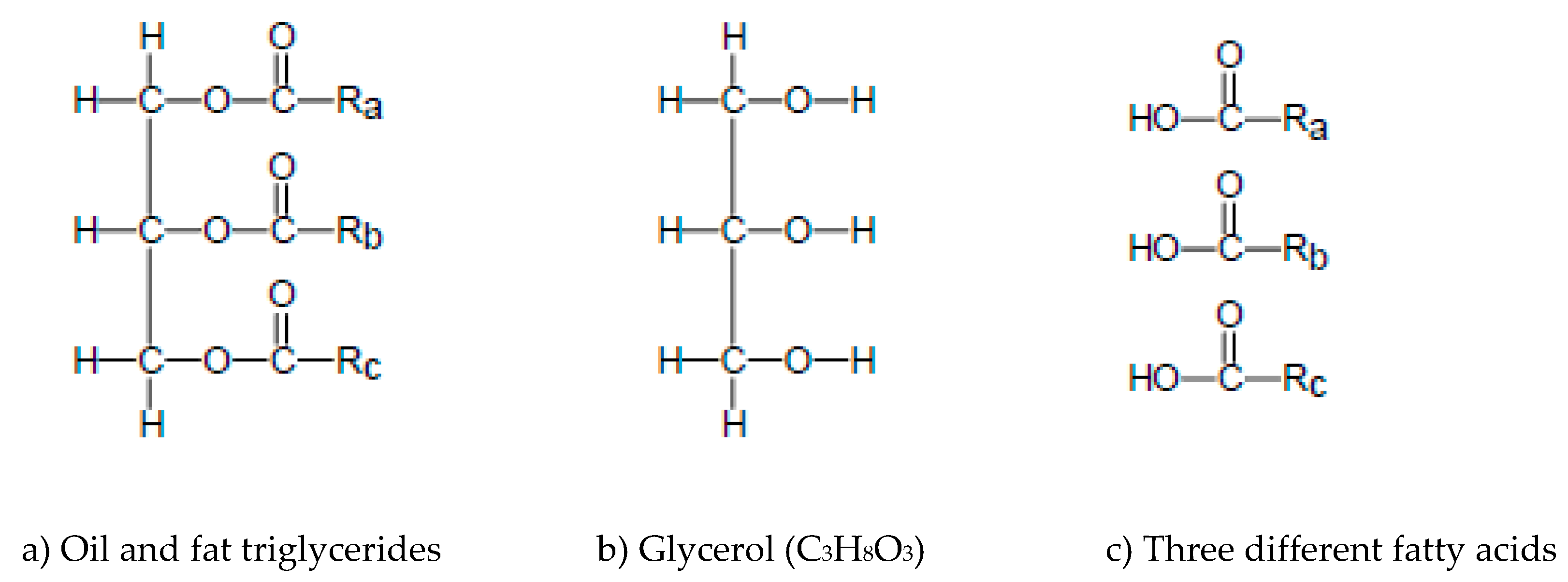
Biomass is any organic matter such as wood, crops, seaweed and animal or fish wastes that can be used as a source of energy. Information on the biochemical and chemical compositions of various biomass feedstocks is presented in Table 1 [23,24,25], noting that the values given are representative of each feedstock type. According to various studies [26,27,28] the use of biofuels in the EU reached 564 PJ in 2012 and is expected to reach about 1216 PJ in 2020, accounting more than 90% of the renewable energy that will be used in transportation. Biodiesel production by feedstock is summarized for the EU, USA and the world in Figure 1 [29,30].
Biodiesel is the main biofuel used in EU transportation systems and in 2016 it was produced mainly by triglycerides from edible vegetable oils such as sunflower oil (3%), soybean oil (7%), palm oil (15%) and rapeseed oil (47%). Non-edible yellow grease and animal fats contributed 18% and 8%, respectively [28]. At the same time, bio-ethanol in the EU is produced using sugars and starches from edible crops such as sugar beet (57.9%), corn (19.8%), wheat (18.8%), barley (1.8%) and rye (1.8%) [28]. These numbers makeclear that the biofuel industry is heavily dependent on edible seeds and crops with obvious food security implications. In view of this problem a 2014 European Council decision has set that in 2020 first generation biodiesel and bio-ethanol from edible raw biomass must not contribute more than 7% of the transportation energy, promoting the production of second generation biofuels from lignocellulosic biomass [31].
Liquid biofuels may be produced by a large variety of biomass feedstocks which can be classified by type as: (a) triglycerides, (b) sugars and starches and (c) lignocellulosic biomass.

2.1. Triglycerides

Oil and fat triglycerides share a common chemical structure as shown in Figure 2a. They have as a backbone the trialcohol glycerol (C3H8O3, Figure 2b) and they are formed by the substitution of the H2 atoms of the three hydroxyl radicals (O–H) of the alcohol by three fatty acid residues. Although vegetable oils are preferred as the main lipid source for biodiesel and green diesel production, animal and fish fats have also great potential for the production of biofuels. Rich triglyceride sources are also waste cooking oils (WCO) such as waste palm oil, waste rapeseed oil and waste sunflower oil [32,33,34].
Table 2 presents typical wt% composition of these fatty acids in the most common vegetable oils and in some animal and fish fats. Vegetable oils have high concentrations of unsaturated fatty acids such as linolenic (18:3), linoleic (18:2) and oleic (18:1) acids. Instead, animal fats have higher concentrations of saturated fatty acids such as stearic (18:0) and palmitic (16:0) [35,36,37].
Microalgae represent a new biomass family which is expected to support the production of the so called “third generation” biodiesel and green diesel fuels. These are primary unicellular organisms that are found in abundance in all aquatic systems and can serve as a plentiful source of triglyceride oils [38,39]. Microalgae have significant growth rates and can be produced in non-arable places, avoiding the undesirable competition for cultivation land. Moreover, research is underway on the genetic manipulation of microalgae for the development of improved strains for each desired final product [40]. The most common fatty acids of microalgae are palmitic (16:0), stearic (18:0), oleic (18:1), linoleic (18:2), linolenic (18:3) and some species may also have eicosapentaenoic acid (20:5) and docosahexaenoic acid (22:6), as shown for some microalgae species in Table 3 [41]. The methods employed for the extraction, characterization and purification of the algae lipids have been recently summarized by Santillan-Jimenez et al. [42].
Green diesel can be produced by a larger range of feedstocks in comparison to biodiesel. The transesterification of an unsaturated feedstock provides a biodiesel blend of unsaturated FAMEs which is susceptible to oxidative instability or may react with the alkaline catalysts to give soaps. As a result, biodiesel production needs special concern on the concentration of the unsaturated fatty acids [13,32]. On the other hand, green diesel is produced through the saturation of the triglycerides with H2 and results in a blend of saturated hydrocarbons regardless the initial feedstock [19,22].

2.2. Sugars and Starches

Simple sugars (e.g., sugar cane and sugar beet) or starches (e.g., corn, wheat and sorghum) may be used as feedstocks for the production of renewable liquid biofuels [43]. The sugars contained into the biomass are transformed into bio-ethanol and CO2 through enzymatic fermentation, a process which is well established in the liquor industry for the production of alcoholic beverages [44]. Starch containing biomass may also be of use after the pretreatment of enzymatic hydrolysis which converts the starch into corresponding sugars [45]. Sugars and starches have been used mainly for the production of bio-ethanol but recently endeavors have also appeared for the catalytic upgrading of carbohydrates into higher hydrocarbons, as it will be discussed in Section 4.

2.3. Lignocellulose

Lignocellulose may be used for the production of useful chemicals and/or biofuels through three technological routes: (a) biochemical conversion into sugars, (b) thermal pyrolysis, and (c) thermochemical gasification. The biochemical conversion of lignocellulose aims at the production of sugars which may then be used for the production of chemicals and/or biofuels through fermentation or other methods. Both cellulose and hemicellulose are carbohydrate polymers which can be transformed into sugars through hydrolysis. Hemicellulose can be hydrolyzed under mild acid or alkaline conditions or by appropriate hemicellulase enzymes. The cellulose fraction is more resistant and requires more potent pretreatment, especially when the lignin content is high. Lignin is acknowledged as a major deterrent to enzymatic hydrolysis because it protects hemicellulose and celullose and makes them less accessible to processing [46,47]. As a result, the biochemical conversion of lignocellulosic biomass requires special lignin pretreatment techniques such as weak and strong acid hydrolysis, lime hydrolysis, ammonia hydrolysis, oxidative delignification (extraction of lignin by chemicals), organosolv processing, steam explosion, CO2 explosion, etc. [48,49,50]. Herbaceous biomass feedstocks have more loosely bound fibers and lower lignin content. As a result, hemicellulose and cellulose are less protected and the biomass is appropriate for biochemical conversion into sugars. On the other hand, woody biomass is comprised of fibers with high lignin content and requires significant lignin pretreatment before biochemical conversion. These feedstocks are more appropriate for thermal or thermochemical conversion without any pre-processing. The last column of Table 1 provides the ratio of cellulose and hemicellulose to lignin, which may indicate the appropriate processing for each lignocellulosic feedstock.

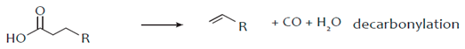
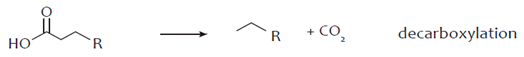
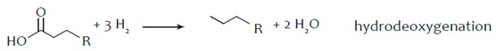
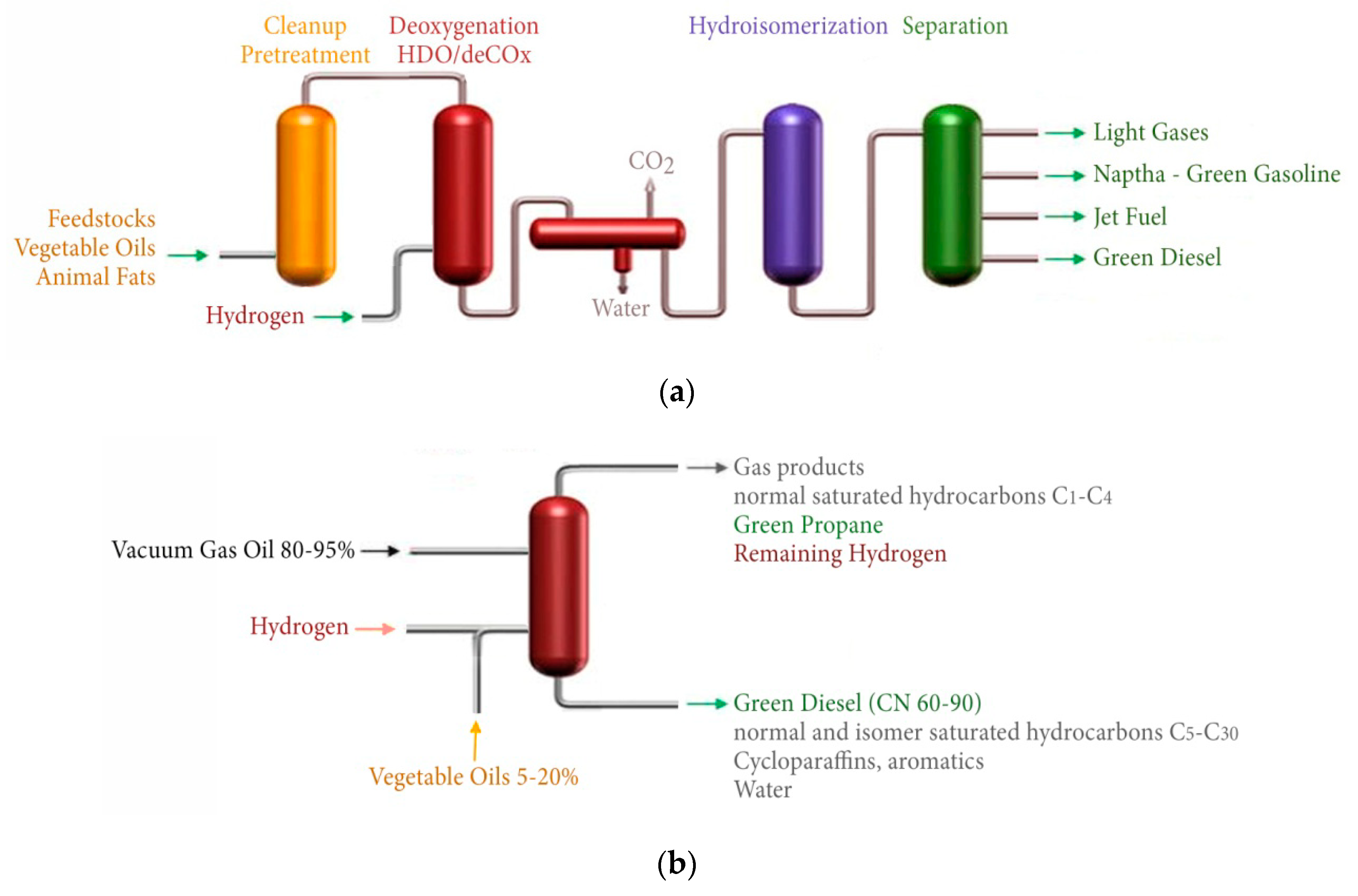
3. Hydro-Processing of Triglycerides

In a conventional refinery hydro-processing describes the catalytic processes in which various petroleum distillates react with H2 at elevated temperature and pressure to form transportation fuels and heating oil. This is accomplished through the destructive hydrogenation of the heavy distillates into lighter with appropriate boiling point and through the non-destructive hydrogenation of the light distillates which improves their quality [51,52]. Destructive hydrogenation or hydrocracking is favored by high temperatures, high hydrogen pressures and strong acid catalysts and catalyst supports (alumino-silicates, silico-alumino-phosphates (SAPO) and zeolites). Typical conditions for the hydrocracking of the petroleum distillates are 350–430 °C at 100-200 bar with a space velocity of 0.2–2 h−1 and H2/feed ratios of 800–2000 m3/m3 [52,53]. Non-destructive hydrogenation is called hydrotreatment and is favored by mild temperatures, mild pressures and catalysts of mild acidity. Of these the most common types are the sulfided Ni–W/Al2O3, Co–Mo/Al2O3 and Ni–Mo/Al2O3 [52] which are also used for the hydrodesulfurization of petroleum distillates [54].
In the biofuel industry hydro-processing describes the chemical reaction of the triglycerides contained in biomass lipids with H2 for the production of liquid hydrocarbon fuels [55]. H2 saturates the double bonds of the triglycerides and under specific conditions may provide different liquid fuels such as green diesel (C15–C18), green jet fuel (C11–C13) and green naphtha (C5–C10). Obviously, the production of light fuels such as green naphtha requires conditions of high temperature, high pressure and strong acidic catalysts and supports that promote hydrocracking. On the other hand, the production of heavy green fuels such as green diesel requires conditions that promote mainly hydrotreatment, although hydrocracking may also be used to a limited extent to cause the isomerization of the hydrocarbons. In this respect, the conversion of triglycerides into green diesel requires mild temperatures in the range of 280–450 °C, pressures of 1–5 MPa and solid catalysts of mild acidity [56]. The sulfided Ni–Mo/Al2O3, Co–Mo/Al2O3 and Ni–W/Al2O3 catalysts mentioned before are the most commonly used catalysts also for the hydrotreatment of the triglycerides and an advantage of the hydro-processing route for green diesel production is that it can be easily accomplished in the existed refinery facilities used for the hydro-processing and hydro- desulfurization of the petroleum fractions [55,56].
The hydro-processing of a triglyceride initiates with the saturation of the double bonds of its fatty acid chains by hydrogen (hydrogenation) and continues with the removal of oxygen from the triglyceride molecules, which converts them into saturated hydrocarbons. The reactions causing the oxygen removal from the triglyceride molecule are commonly termed as reactions of selective deoxygenation (SDO) and may be further classified into the reactions of hydrodeoxygenation (HDO), decarbonylation (deCO) and decarboxylation (deCO2), as shown in the following reactions [55,56]:
Energies 12 00809 i001
Energies 12 00809 i002
Energies 12 00809 i003
Decarboxylation and decarbonylation are commonly referred as deCOx reactions. In decarboxylation the O2 molecules are removed in the form of CO2 while in decarbonylation the oxygen molecules are removed as CO and H2O. In both these deCOx cases the saturated hydrocarbon produced has one C atom less than the parent fatty acid chain in the triglyceride. In HDO the oxygen molecules are removed exclusively as H2O and the saturated hydrocarbon has an equal number of C atoms with the corresponding fatty acid bound in the triglyceride. As a result, the saturated hydrocarbons produced by the hydro-processing process will have about the same C atoms with the fatty acid chains of the triglycerides. The three SDO reactions form a complex mechanism in which the accurate determination of their individual contribution is generally difficult. However, the catalytic preference to deCOx or HDO reactions may be estimated by the distribution of the liquid hydrocarbons and the C17/C18 ratio and the preference between the deCO2 and deCO reactions may be found through the CO2/CO ratio [55,57]. The conversion of the triglycerides, the degree of deoxygenation (DOD) and the yield of normal saturated hydrocarbons tend to increase with the reaction temperature in both batch and continuous reactors. However, the yield of C15–C18 hydrocarbons maximizes at an optimal temperature and then reduces due to hydrocracking and reverse water gas shift (RWGS) reactions. Higher H2 pressures have been observed to enhance both the yield of hydrocarbons and the selectivity to green diesel. Also, the higher H2 pressures promote the HDO reaction pathway [39]. The H2 consumption obviously depends on the chemistry of the feedstock. Highly unsaturated oils such as rapeseed oil and fish oils require higher H2 consumption since they have more double bonds. Finally, in all cases, propane (C3H8) is produced as a side product together with H2O, CO and CO2 from the SDO reactions.
The deoxygenation of triglycerides provides a green diesel consisting mainly of normal (straight chain) saturated hydrocarbons in the C15–C18 range. These hydrocarbons have a high cetane number but poor cold flow properties since they have a high freezing point above 15 °C [58]. One solution to this problem is to blend green diesel with petroleum diesel as a cetane number improver. Another solution to this problem comes with the hydroisomerization of the normal saturated hydrocarbons into branched chain isomers with lower freezing point appropriate for use in engines under cold weather and cold start conditions, though with the cost of lower cetane numbers [55,56]. Isomerization changes the structure of a molecule leaving its molecular weight the same. Given that saturated hydrocarbons are not prone to direct isomerization they must be processed in an appropriate way and hydroisomerization is an appropriate technique in this direction. The hydroisomerization of a saturated hydrocarbon takes place in three steps starting with its dehydrogenation into the same carbon atom alkene and proceeds with the skeletal isomerization of the alkene and its final hydrogenation into the branched isomer saturated hydrocarbon. This three step process is feasible in light saturated hydrocarbons with less than 7 carbon atoms but it is generally difficult for heavier molecules without some extent of hydrocracking [59]. In the case of the heavy saturated hydrocarbons of the green diesel, isomerization needs a balanced action of hydroisomerization and hydrocracking over an appropriate heterogeneous catalyst that can increase selectivity to the desired isomer hydrocarbons [60,61]. This is achieved by using acidic catalysts such as commercial FCC catalysts, zeolites or other supports. The hydromerization of green diesel may lower the freezing point from 20 °C below −10° causing also a drop of the cetane number from about 100 to 70.
The global market of green diesel is growing in great volumes, from 330 × 106 gallons in 2011 to 2.1 × 10⁹ gallons in 2017 [62]. A list of the main green diesel producers is given in Table 4 [63]. Most of the producers have developed proprietary technologies (Neste NExBTL, UOP/Eni EcofiningTM, UPM BioVerno etc.) and standalone plants comprised by the biomass cleanup and pretreatment section, the deoxygenation (hydrotreatment) section, a hydroisemarization reactor and a separation column, as shown in Figure 3a. Given that green diesel can be mixed with conventional petroleum diesel to satisfy the automotive fuel specifications, some oil refineries have developed methods for the simultaneous co-processing of triglyceride feedstocks with petroleum intermediates such as straight run gas oil and/or vacuum gas oil, as shown in Figure 3b [55,56]. This is economically attractive for the existing refineries which can combine the hydrotreating of the triglycerides with the hydrodesulfurization of the gas oil in the same reactor and over the same sulfided catalysts such as Co–Mo/Al2O3 and Ni–Mo/Al2O3. The co-processing typically takes place at 350–450 °C and 50–100 bar by mixing 5–20% vegetable oils with 80–95% gas oil and leads to gas phase products such as C1–C4 saturated hydrocarbons, green propane, CO, CO2 etc., and liquid phase products such as straight C5–C30 hydrocarbons with high yields to C15–C18 green diesel [55].
Catalytic research on the hydrotreatment of the triglycerides has mostly focused on the sulfided catalysts Ni–Mo/Al2O3 [64,65,66,67,68,69,70,71,72,73,74,75,76,77,78,79,80], Co–Mo [71,75,77,80,81,82,83,84,85], and Pt on various supports [74,84,86]. Ni–, Co– and Mo– based catalysts are preferred to noble metals as they show high activity, while they also have low cost. Srifa et al. [87] have examined the monometallic catalysts Ni, Co, Pt and Pd supported on Al2O3 and found that the catalytic activity was of the order Co > Pd > Pt > Ni. They also observed that only Co promotes HDO stronger than deCOx reactions. Ni and Co are often used as promoters to increase the activity of molybdenum sulfide, as it is believed that they donate electrons to Mo, which weakens the metal–sulfide bond. However, it has been found that the activity of the sulfided catalysts decreases over time due to a loss in MoS2 active sites and to the presence of water due to HDO. This means that a continuous supply of a sulfiding agent, such as H2S, is necessary in order to avoid either the oxidation of the sulfide catalyst or the reduction by H2 of the sulfide phase [88]. Kubĭcka and Kaluža [72] have examined the deoxygenation of rapeseed oil over sulfided Ni, Mo and Ni–Mo catalysts supported over Al2O3 and observed that Ni produces exclusively n-C17H36 and no n-C18H38 while Mo produces only a small fraction of C17H36 and almost exclusively C8H18. This behavior implies that Ni promotes exclusively the deCOx of the fatty acids while Mo promotes their HDO. This is explained by the inherently different electronic properties of the Mo and Ni sulfided phases. In the Ni-Mo catalyst, both n-C17H36 and no n-C18H38 were observed as products in appreciable quantities with a C17/C18 weight ratio equal to 0.36 (at 260–280 °C, 35 bar and Liquid Hour Space Velocity, LHSV, = 0.25–0.4 h−1). Given that Ni was used as a promoter in lower concentration than Mo, it was deduced that over Ni-Mo the main product is n-C18H38 and the main reaction pathway is HDO [72]. Laurent et al. [89], examined the impact that H2O and H2S have on the HDO of guaiacyl, carboxylic and carbonyl groups, using NiMo/CoMo catalysts that were based on γ-Al2O3, and concluded that Brønsted acidity of the sulfide phase increases in the presence of H2S during the reaction. Toba et al. [80] have examined the hydrotreatment of waste cooking oil (WCO) using sulfided Ni–Mo/Al2O3, Co–Mo/Al2O3, and Ni–W/Al2O3 catalysts and observed that although all catalysts have high catalytic activity for production of C15–C18 hydrocarbons there exists a small difference in the order Ni–Mo > Ni–W > Co–Mo. At the same study, the effect of the support was examined on Ni–Mo/Al2O3 and Ni–Mo/B2O3–Al2O3 catalysts and it was shown that due to higher acidity, B2O3–Al2O3 increases the production of branched isomers and improves the cold fuel properties of the biofuel. Phosphorus has also been tried as a promoter of Mo-based catalysts during hydrotreatment of bio-oil and model compounds. It was concluded that phosphorus enhances the dispersion of Mo on to the support, helps reduce the formation of coke, favors the creation of new Brønsted and Lewis acid sites on the surface of the support and increases the packing of MoS2 crystallites [90]. As is well understood, the nature of the support can have a significant effect on the performance of a catalytic system and as a result a number of different metal oxides, such as Al2O3, TiO2, ZrO2 and CeO2 have been tested as carriers [91]. As alumina supports have been used extensively for the removal of sulfur from crude oil (upgrading of oil), a number of authors have examined its performance for hydrodeoxygenation in bio-oil upgrading. The main issues identified are the susceptibility of alumina to attack by acidic water at elevated conditions and its reaction with H2O which leads to a reduction of surface area [92]. Moreover, as alumina is not inert (as it possesses acid centers, mainly of Lewis type), promoters such as Ni and/or Co can react with Al2O3 and take up tetrahedral and octahedral sites found in the external layers [93]. As a consequence, a strong interaction develops between the support and the modifier, which in turn inhibits the dispersion of the Mo sulfide phase and affects HDO activity in a negative way [94]. The effect of the support has been examined also by Kubĭcka et al. [75] who examined the hydrotreatment of rapeseed oil over Co-Mo supported on Al2O3, MCM-41 and Organized Mesoporous Alumina (OMA) and shown that the formation of branched isomers follows the order OMA > Al2O3 > MCM-41. A promising supporting material for HDO is activated carbon (AC) due to its thermal stability, high surface area and pore volume, presence of both meso and macro pores and hydrophobic nature [95,96]. Supelveda et al. [95], using a Mo2N/AC catalyst reported that the high mesoporosity of the activated carbon facilitated the diffusion of the reactants to the internal surface area, i.e., at the location of the active centers. Moreover, Echeandia et al. [96] argued that the hydrophobic nature of activated carbon prevents the water produced during HDO from being adsorbed on the catalyst’s active sites. SiO2 has also been used in HDO reactions as it is known to be inert and to have a small interaction with the sulfide phase. For example, Popov et al. [97] studying the HDO of phenolic molecules reported that the phenolic compound interacted through H bonding. The authors also reported that phenate formation on the silica surface was very low in comparison to Al2O3 support. MgO has also been used as supporting material in hydroprocessing reactions; for example, Yang et al. [90] investigated CoMo catalysts supported on MgO for the hydroprocessing of phenol and reported high coke resistance which they attributed to the acidic nature and high dispersion of MoO3/MoS2 on the MgO surface.
By comparing the three deoxygenation reactions one observes that hydrogen consumption is higher in the order HDO > deCO > deCO2 and, therefore, deCOx reactions are preferable despite the expense of carbon loss into CO and CO2. Also, HDO reaction over sulfided metal catalysts can contaminate the products with sulfur [91] and requires high H2 pressures that are mostly available only in centralized refineries. From the discussion above it is clear that there is great need for the development of deoxygenation catalysts that will be free of sulfur, and at the same time be highly active and selective and also resistant to deactivation in low H2 pressure. The deCOx reactions are catalyzed by simpler supported metal catalysts and also need lower H2 pressures. Due to these advantages research was undertaken for the selective deoxygenation of triglycerides over catalysts that promote the deCOx such as Pt, Pd [74,84,86,98] and especially Ni-based catalysts which show comparable activity to noble metals at a much lower cost [91,99,100,101]. Peng et al. examined the HDO of stearic acid over Ni catalysts supported on two types of zeolites, HZSM-5 and HBeta [102]. The authors reported that Ni/HBeta catalysts were more selective to C17 and C18 alkanes promoting the HDO reaction and eliminating cracking. In contrast, the narrower pores and higher concentration of Brönsted acid sites of the Ni/HZSM-5 catalysts led to a higher effective residence time, which in turn resulted at an increased degree of cracking. Thuan Minh et al. [103] investigated the catalytic HDO of phenol over Ni–Cu/HZSM-5 and Ni–Co/HZSM-5 bi-metallic catalysts and found that the conversion and selectivity was decreased with the addition of Cu, and attributed this behavior to a negative synergistic effect. In contrast, the addition of Co (10Ni–10Co) resulted in an increase of activity and selectivity, due to the formation of a NiCo2O4 spinel phase, which also improved resistance to coke deposition. Wu et al. [104] examined the effect of the support on non-sulfided catalysts that were based on Al2O3, ZrO2 and SiO2 for Ni2P catalyst on the HDO of guaiacol. The acidic strength decreased in the order of Al2O3 > ZrO2 > SiO2, which was also the case for the Ni2P catalysts (i.e., the different supports had analogous acidic strengths). SiO2, being the support with the lowest acidity, led to the strongest association with Ni and also allowed P to maintain its fully phosphided state; it also led to decreased coke deposition. Lercher et al. [105] used a number of different supports and active phases in order to investigate the HDO of palmitic acid and reported that activity decreased in the order of: 15%Ni/ZrO2 = 5%Ni/HZSM-5 (Si/Al = 200) > 5%Ni/HBEA[d] (SiAl = 180) > 10%Ni/ZrO2 > 5%Ni/ZrO2 > 5%Pd/ZrO2 > 5%Pt/ZrO2 > 3%Ni/ZrO2 > 5%Ni/Al2O3 > 5%Ni/SiO2 > 5%Pt/C > 5%Pd/C. The zeolites and ZrO2 with weak and medium acid sites on the surface exhibited much higher catalytic activity than the SiO2, Al2O3 and activated carbon, with the same nickel content. The authors also argued that ZrO2 participated in the HDO process, leading to the much higher activity. Kumar et al. [106] examined the deoxygenation of stearic acid over Ni/HZSM-5, Ni/Al2O3 and Ni/SiO2, with weak and medium acidity. The results showed that the Ni/HZSM-5 was more active (two times higher) than the Ni/Al2O3 and Ni/SiO2, however, the Ni/HZSM-5 exhibited high selectivity to octadecane while the other two catalysts were more selective to heptadecane. Similarly, Zuo et al. [107] prepared sulfur-free Ni catalysts supported on SiO2, γ-Al2O3, SAPO-11, HZSM-5, and HY and tested them in the HDO of methyl palmitate to produce renewable diesel. The acidic strength of the catalysts increases in the order of: 7wt% Ni/SiO2 < 7 wt% Ni/ SAPO-11 < 7wt% Ni/γ-Al2O3 < 7wt% Ni/HZSM-5 < 7wt% Ni/HY. Moreover, the Ni/SAPO-11 catalyst exhibited higher catalytic activity in comparison to the other samples, which the authors attributed to the presence of both weak and medium strength acid sites present in the SAPO-11 support. An extensive review on the development of Ni-based catalysts for the transformation of the natural triglycerides into green diesel has been published recently by Kordulis et al. [91]. A review of the catalytic research on the hydro-processing of the triglycerides is presented in Table 5 [72,73,74,75,76,77,78,79,80,81,82,83,84,85,86,87,88,89,90,91,92,93,94,95,96,97,98,99,100,101,102,103,104,105,106,107,108,109,110,111,112,113,114,115,116,117,118,119].

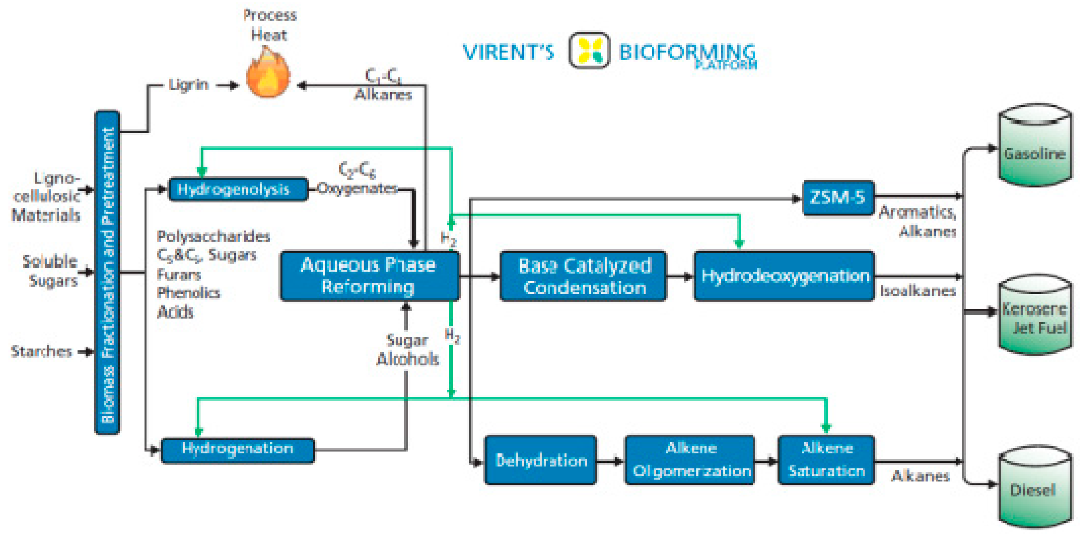
4. Catalytic Upgrading of Sugars, Starches and Alcohols

Since 2006 Virent Energy Systems Inc. (Madison, WI, USA) has developed a platform of processes for the conversion of carbohydrates into liquid fuels like green gasoline, green jet fuel and green diesel, as shown in Figure 4 [120].
The platform is known as BioForming® and involves liquid phase technologies such as hydrolysis, hydrogenation, hydrogenolysis, dehydration, isomerization, oxidation, aqueous phase reforming (APR) and aldol condensation [121,122,123,124,125]. Biomass (lignocellulosic, sugars, starches) is initially pretreated with dilute sulfuric acid catalyst (0–3 wt%) at about 130–220 °C for 2–30 min. This breaks down the biomass for a subsequent enzymatic hydrolysis with the cellulase enzyme which converts polysaccharides like cellulose, hemicellulose, starch and inulin into a hydrolysate slurry of monosaccharides such as xylose, fructose and glucose. The slurry is then purified from insoluble solids, proteins and inorganic compounds which are problematic for the operation of the plant equipment and catalysts and after possible hydrogenation or hydrogenolysis in pretreatment reactors it is finally routed to the catalytic reactor of aqueous phase reforming (APR) with a sugar concentration between 10 and 15 wt% [125]. During APR the hydrolysate slurry reacts with water which converts the sugars and sugar alcohols into H2, CO2, lower saturated hydrocarbons, and condensable chemical intermediates at temperatures about 175–300 °C and pressures of 10–90 bar over supported metal or metal alloy catalysts such as Pt or Ni-Sn [125,126,127]. The specific mixture composition depends on the reactor design, process conditions, feed concentration, solution pH, catalyst support and catalyst. The reactions involved are considered to be (a) the reforming of the sugars which produces H2, (b) the dehydrogenation of alcohols, (c) the hydrogenation of carbonyls, (d) deoxygenation reactions, (e) hydrogenolysis and (f) cyclization. In situ generation of H2 from APR is considered of key importance for the de-functionalization of the very reactive carbohydrate to a less reactive mono-oxygenated species (alcohol, ketone or aldehyde) which can then be converted into a non-oxygenated hydrocarbon through conventional catalytic condensation and hydrotreating techniques [120]. Any excess H2 is recycled to upgrade the aqueous solution of complex C5 and C6 sugar mixtures upstream the APR reactor through the reactions of hydrogenation and hydrogenolysis. Hydrogenation takes place in the presence of hydrogen at 100–150 °C and 10–30 bar causing the saturation of the C=C, C=O and C–O–C bonds over metal catalysts such as Ru, Pt, Pd and Ni. Hydrogenolysis occurs in presence of hydrogen at 125–230 °C and 14–300 bar causing the selective cleavage of C–C or C–O bonds of specific molecules like glycerol for the production of more valuable polyols or diols which are useful in the production of chemical polymers [128]. Hydrogenolysis takes place under alkaline conditions over supported metal catalysts such as Ru, Pd, Pt, Ni and Cu [128,129,130,131]. The effluent of the APR reactor contains oxygenated molecules such as alcohols, ketones, aldehydes and organic acids with less than six carbon atoms that can be converted into the desired liquid fuel in subsequent chemical processes. Green gasoline is produced through direct catalytic condensation using acid catalysts such as solid acids and zeolites like the ZSM-5 zeolite catalyst employed by Virent. On the other hand, green jet fuel is produced through a base catalyzed route. Finally, green diesel may be produced through dehydration, alkene oligomerization and alkene saturation.
Alkenes or olefins are unsaturated hydrocarbons with one double bond (C=C) and general chemical formula CnH2n. Traditionally they are produced by the steam or catalytic cracking of fossil hydrocarbons but as oil resources are decreasing production routes are becoming increasingly expensive. Catalytic dehydration is an alternative pathway for the production of alkenes from oxygenated feedstocks and a first step for the production of higher hydrocarbons. The dehydration of an alcohol takes place through acidic catalysis and provides the corresponding alkene with the same number of carbon atoms. SAPO-34 has shown excellent performance on the dehydration of methanol [132,133,134,135,136] and high activity on the dehydration of ethanol and butanol [126,127]. Zeolites such as HZSM-5 [137,138,139,140,141,142] and mesoporous Si-based materials such as Ni-MCM-41 and Zr-KIT-6 [143,144,145,146,147] have also shown good dehydration activity. According to various studies [145,148,149] materials with fewer Brønsted and more Lewis acid sites provide higher selectivity to the desired alkenes and show better stability since they are less conducive to carbon formation and deposition. In the case of the APR effluent the dehydration of alcohols is straightforward but the ketones, aldehydes and organic acids which are present can also be dehydrated after catalytic hydrogenation which will cause their reduction to the respective primary or secondary alcohols.
Oligomerization describes a reaction which produces molecules with only a few monomer units in contrast to polymerization which produces large molecules of high molecular weight. Alkene oligomerization describes the conversion of lower alkenes such as propylene, butylene and pentene to heavier alkenes in the boiling range of gasoline and petroleum diesel. The reaction may proceed over acid catalysts such as zeolites or over supported Ni catalysts [150,151,152,153,154]. Two commercial processes of alkene oligomerization are the Mobil Olefins to Gasoline and Distillates (MOGD) [154,155] and Conversion of Olefins to Diesel (COD) ones [156,157,158]. The MOGD process appeared in 1982 at the former Mobil refinery in Paulsboro in New Jersey, USA, in combination with Mobil’s successful fluidized bed Methanol to Olefin (MTO) technology. The success of these technologies lies on the unique properties of Mobil’s shape selective zeolite catalysts like H-ZSM-5 which inhibit carbon formation reactions and promote the selective production of high quality diesel range (C10 to C20) iso-alkenes. After hydrogenation these provide a mixture of saturated hydrocarbons on the diesel boiling point with a cetane number slightly above 50. On the other hand, the COD process was developed by Air Liquide (formerly Lurgi) during the 1990s. A COD reactor normally operates at about 120 °C with a zeolite catalyst like H-ZSM-5. The reactor operates discontinuously due to the deposition of heavy hydrocarbons on the catalyst which reduce its activity. As a result, at the end of each catalyst cycle the operation is discontinued and the catalyst is regenerated. Due to this three or more COD reactors are operated in a staggered sequence. The effluent stream of the COD reactors contains alkenes with a wide range of carbon atoms, starting from a small amount of propylene (C3H6) and up to heavy C23H46. The distribution curve shows a dominant maximum on the gasoline range, for C12H24. After hydrogenation the effluent produces a diesel fuel with a cetane number close to 56.

5. Thermal Conversion of Lignocellulosic Biomass

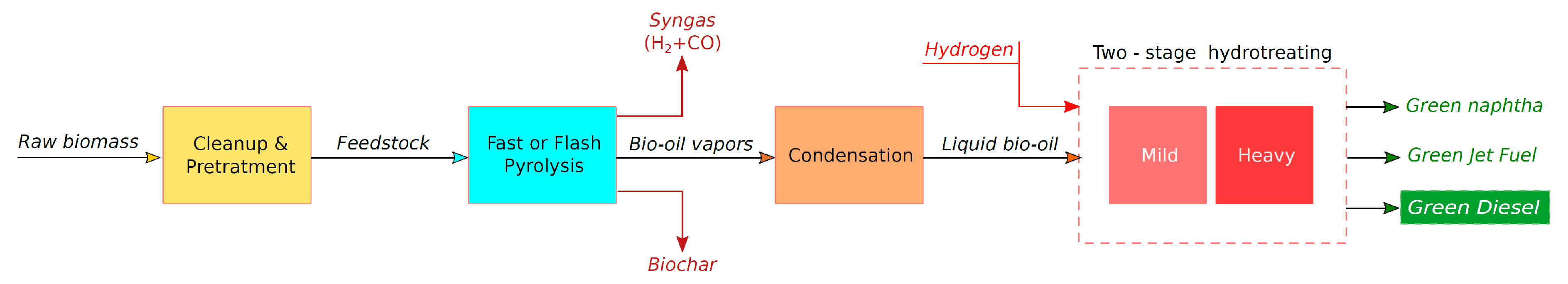
5.1. Biomass Pyrolysis and Production of Bio-Oil

Pyrolysis is the endothermic reaction that takes place by heating lignocellulosic biomass at 300–900 °C in absence of air. Most of the pyrolysis research has been conducted using different types of woods but other feedstocks have also been tested such as forest residues and agricultural residues such as straw, willow, olive pits and nut shells [159,160]. The pyrolysis products are biochar (a black solid residue), syngas (a mixture of H2 and CO), and bio-oil (a brown liquid).
Bio-char is a high carbon, fine-grained solid residue. It has potential as a solid fuel for the generation of heat and power or as a soil improver and a ground storage medium for the atmospheric greenhouse gases. It was found to benefit soil health by retaining both water and water soluble nutrients [161]. This can increase crop production in soils that are degraded and nutrient poor and can provide cost benefits decreasing the needs for irrigation and fertilizers [162]. Land bio-char applications are also environmentally desirable as they remove CO2 from the atmosphere and facilitate long term carbon sequestration. Bio-char can also store large amounts of greenhouse gases in the ground [163,164,165,166].
Apart from H2 and CO, the pyrolysis syngas also contains small amounts of CO2, H2O(g)), N2, CH4, ethylene (C2H4), ethane (C2H6), tar and ash in a quantitative composition that depends on the process conditions and the biomass feedstock. H2 production is due to the thermal cracking and gaseous reforming of hydrocarbons and generally increases with temperature. On the other hand, CO and CO2 are produced by the thermal cracking of oxygenated organic compounds such as cellulose. Methane, ethylene and ethane are also formed by the thermal cracking of higher hydrocarbons. The syngas formed by pyrolysis may be combusted to provide heat or may be used as a fuel in industrial processes, internal combustion engines and Solid Oxide Fuel Cells (SOFCs). Moreover, syngas may be used as the reactant mixture for the production of synthetic chemicals and fuels through the well-known Fischer-Tropsch process, especially when the H2/CO molar ratio is close to 2.
Bio-oil contains highly oxygenated organic molecules such as carbohydrates, phenols, alcohols, aldehydes, organic acids and lignin-derived oligomers with a specific composition which depends on the biomass feedstock as shown for some typical cases in Table 6 [94,167,168,169].
It is also shown that bio-oil is significantly different to any petroleum distillate fuel. Bio-oil has a high content of water which is produced during pyrolysis through chemical dehydration of cellulose and hemicellulose and also it is acidic with a pH of approximately 2–3 due to the presence of organic acids [167]. The elemental composition of bio-oil is close to the composition of biomass and as a result it has a similar heating value of 16–19 MJ/kg which is, however, significantly lower than the heating value of petroleum fuels [94]. Due to low heating value, high viscosity, low pH and high water content crude bio-oil is generally regarded as inappropriate for direct use in CI engines or turbines. Bio-oil’s acidity is corrosive to the engine parts (injection nozzles, fuel pumps, pressure valves, seals, gaskets etc.) and its high water content impedes autoignition. For this reason it is generally agreed that bio-oil is not appropriate in high speed engines. Furthermore, various tests have shown that crude bio-oil produces also a number of engine problems such as excessive carbon deposition inside the engine cylinders, poor atomization during injection and increased engine wear. Although bio-oil is a poor engine and burner fuel it is a valuable intermediate for the production of biofuels and pyrolysis optimization for high bio-oil yield is important [169].
Depending on the heating rate of the biomass feedstock three pyrolysis processes are distinguished: a) slow pyrolysis, b) fast pyrolysis and c) flash pyrolysis. Slow pyrolysis takes place in batch reactors at 550–950 °C heating biomass particle sizes of 5–50mm with a heating rate of about 0.1–1 °C/s for periods of 5–30min. It typically produces biochar, uncondensed gases and bio-oil in the approximate proportions of 35, 35 and 30 wt%, respectively [170]. Fast pyrolysis takes place in continuous flow reactors by rapidly heating dry biomass particles (<1 mm) with a heating rate of about 10–200 °C/s up to about 850–1250 °C within 0.5–10s and typically yields biochar, syngas and bio-oil at the proportions of 15–25, 10–20 and 60–75 wt%, respectively. Finally, flash pyrolysis may be accomplished by an extremely fast heating of biomass particles (<0.2 m) up to 1050–1300 °C in less than 0.5s and is capable to provide biochar, syngas and bio-oil at proportions 12, 13 and 75 wt%, respectively. Maximum bio-oil production requires a moderate reaction temperature (about 500 °C), fast heating of the biomass particles, short residence time of the feedstock in the reactor (typically less than 2 s), fast removal of product char to minimize vapor cracking and the quick dampening of the pyrolysis vapors in order to condense the bio-oil [171]. These conditions are feasible through properly controlled fast or flash pyrolysis. Then bio-oil may be upgraded to liquid transportation fuel through a) hydrotreating, b) catalytic vapor (zeolite) cracking or c) through gasification into syngas and subsequent Fischer-Tropsch synthesis. Bio-oil hydrotreating and zeolite cracking are analyzed in the following paragraphs. Gasification and production of synthetic fuels will be discussed in Section 6.

5.2. Bio-Oil Upgrading through Hydrotreating

A typical pyrolysis and bio-oil hydrotreating pathway is shown schematically in Figure 5. Biomass is reduced in particle sizes of about 2–6 mm and is dried at approximately 10 wt% water. Fast or flash pyrolysis follows with the rapid heating of the feedstock at about 500 °C in less than 1 s, usually in a fluidized bed reactor. Any solid matter and solid char is removed through cyclones and the bio-oil vapor exits the reactor. Bio-oil vapor is then quickly liquefied in a condenser providing the brown liquid bio-oil with an approximately 75% yield on a dry weight basis. Then, the bio-oil hydrotreating occurs in two stages, as shown in Figure 5 [172]. At the first stage the mild hydrotreating of bio-oil takes place at about 240 °C and 170 bar in excess of hydrogen over a conventional hydrotreating catalyst such as the sulfided Co–Mo/Al2O3 or Ni–Mo/Al2O3. This is used to hydrogenate and stabilize various active species such as carbonyl and phenolic compounds which are present in the bio-oil and can undergo reactions of depolymerization and condensation which will promote carbon formation and catalyst deactivation [173]. At the second stage heavy hydrotreating takes place at about 370 °C and 140 bar in excess of hydrogen over sulfided Co–Mo/Al2O3 or Ni–Mo/Al2O3. This causes the deoxygenation of bio-oil and the production. of a mixture of saturated hydrocarbons which is then distilled to provide fractions of light gases, naphtha, green diesel and heavy distillates. The latter will undergo additional processing through hydrocracking and they will provide extra yields of naphtha and green diesel.
Bio-oil hydrotreating involves deCOx reactions but proceeds mainly through hydrodeoxygenation (HDO), as shown on the following conceptual reaction proposed by Bridgwater [171]:
C1H1.33O0.43 + 0.77H2→ CH2 + 0.43H2O
where CH2 represents an unspecified hydrocarbon product. The catalysts which were originally examined were the sulfided Co-Mo and Ni-Mo supported on Al2O3 or alumino-silicate which are well known for their efficiency in the desulfurization of petroleum distillates [174]. However, these catalysts suffered from low stability due to the high water content of the bio-oil. Also, due to gradual loss of sulfur they were requiring frequent re-sulfurization. Research was then focused to noble metal catalysts on various supports like Pd/C, Pt/Al2O3-SiO2, Ru/Al2O3, Ru/C and Ru/TiO2. A brief review of the research of bio-oil hydrotreating on these catalysts is presented in Table 7 [175,176,177,178,179].

5.3. Bio-Oil Upgrading through Catalytic Vapor (Zeolite) Cracking

In a conventional refinery fluid catalytic cracking (FCC) is used to convert the high molecular weight and high boiling point fractions of petroleum into more valuable lighter products such as gasoline or gases. The cracking of these heavy distillates was originally accomplished by thermal cracking, but it has been replaced almost completely by catalytic cracking because it produces higher yields of gasoline with high octane rating. Bio-oil upgrading can take place through chemical reactions similar to FCC in a process known as catalytic vapor cracking or zeolite cracking. Zeolite cracking removes oxygen from the bio-oil as CO2, as shown in the following conceptual reaction [171]:
C1H1.33O0.43 + 0.26O2→ 0.65CH1.2 + 0.33CO2 + 0.27H2O
where CH1.2 represents an unspecified hydrocarbon product. The process typically takes place between 300 and 600 °C over zeolite catalysts which are also used in the FCC industry. A brief review of the research of bio-oil zeolite cracking is presented in Table 8 [180,181,182,183].
HZSM-5 is considered a good catalyst for bio-oil upgrading through zeolite cracking as it provides high yields of liquid oil and propylene.

5.4. Hydrothermal Liquefaction of Biomass and Upgrading of Bio-Crude

Hydrothermal liquefaction (HTL), also known as hydrous pyrolysis or direct liquefaction, is another thermal technology used for the conversion of biomass into a liquid product similar to bio-oil which is usually called bio-crude. During the HTL process the biomass is converted directly into bio-crude and other aqueous, gaseous and solid phase byproducts in presence of a solvent and sometimes of a catalyst. The most common solvent is water but it usually produces low yields of bio-crudes with higher oxygen content and lower heating values. Other organic solvents such as alcohols, phenol, esters, ketones, tetralin and various alcohol-water mixtures can provide higher bio-crude yields with lower oxygen content and can serve also as donors of hydrogen during the process [184]. The catalyst may be used to inhibit the formation of char and tar [185]. This is usually a homogeneous catalyst such as sulfuric acid, oxalic acid, hydrochloric acid, sodium hydroxide or a metallic salt but various heterogeneous catalysts are also under investigation.
The HTL process usually takes place at temperatures of 200–400 °C and at elevated pressures of 50 to 200 bar with relative long residence times of 10–60 min. The high process pressure sustains the produced solvents in the liquid state and increases the yield of liquid bio-crude but also increases the cost of the HTL technology. The mechanism of the HTL process is complex and still under investigation. It proceeds with the depolymerization of the biomass macromolecules into smaller compounds and with various chemical and thermal decompositions of monomers by cleavage, dehydration, decarboxylation and deamination (removal of aminoacids) which create smaller fragments and remove oxygen from the biomass product. Finally the created fragments are rearranged through condensation, cyclization and repolymerization [184,186]. Ramirez et al. [187] have reported that the chemical composition of bio-crudes varies significantly and contains various groups of chemicals such as phenolics, esters, aromatics and heterocyclics, aldehydes, carboxylic acids, ketones, saturated hydrocarbons and nitrogenates. A general comparison of HTL bio-crudes with the pyrolysis bio-oils shows that bio-crude has a higher carbon content (68–81% vs. 56–66%), lower oxygen content (9–25% vs. 27–38%), lower water content (6–25% vs. 24–52%) and higher heating value equal to about 28–41 MJ/kg [187,188]. On the other hand, HTL bio-crude has a much greater viscosity than bio-oil, petroleum diesel and biodiesel.
Although similar to the biomass pyrolysis, the HTL does not need the preliminary drying of the feedstock and therefore wet feeds of lower cost can be exploited such as the microalgae which are cultivated in aqueous media. Dimitriadis and Bezergianni [189] have reviewed the most useful biomass feedstocks studied for HTL including lignocellulosic (woody) biomass, wastes (sewage sludge, solid wastes, swine manure, pulp/paper sludge powder, agricultural residues and food processing wastes) and microalgae. According to their review, the yield of bio-oil from these sources ranges between 15 and 68 wt% depending on the feedstock type and size, the operation parameters, catalyst and solvent type and solvent to biomass mass ratio. Xu et al. [190] have reviewed the catalytic HTL of algae over homogeneous catalysts such as CH3COOH, HCOOH, KOH and Na2CO3 and have reported that Na2CO3 provides the highest bio-crude yields between 20.4 and 51.6% for various algae varieties at 280–360 °C and with residence times of 30 and 60 min. The same study also reviewed the HTL of algae over various heterogeneous catalysts such as Pd/C, Pt/C, Ni/SiO2-Al2O3, CoMo/Al2O3, Ce/HZSM-5 and Ru/C and concluded that Ni/SiO2-Al2O3 is the best option in terms of bio-crude yield and cost and Ce/HZSM-5 is the best option in terms of bio-crude quality providing high hydrogen content, high heating value, high yield and low heteroatom content.
Due to the similarity of pyrolysis bio-oil and HTL bio-crude, the upgrading of the bio-crude is accomplished with the same hydrotreating and zeolite cracking technologies mentioned before in the Section 5.2 and Section 5.3. The hydrotreatment of bio-crude may proceed in two stages as it was discussed also for bio-oil and over the same catalysts. The initial mild hydrotreatment stage is useful also in this case to avoid carbon deposition due to the bio-crude content in carbonyls but it was shown that the upgrading of HTL bio-crude may also proceed in a single step [191,192]. For example an oxygen removal higher than 95% was achieved in wood derived bio-crude at 300 °C over a sulfided CoMo/Al2O3 catalysts resistant to carbon formation due to its desalting pretreatment [192]. The second stage heavy hydrotreatment process may follow over the same catalysts proposed in Table 7. Grlic et al. [193] investigated the hydrotreatment of lignocellulosic biomass bio-crude over NiMo/Al2O3, Pd/Al2O3, Pd/C, Ni/SiO2-Al2O3 and bulk MoS2 at 300 °C, 80 bar and 60 min. Their results have shown that the sulfided NiMo/Al2O3 catalysts provide a liquid product with appropriate HHV, rheological properties and yield. The Pd/Al2O3 and Pd/C catalysts exhibited low catalytic activity and the bulk MoS2 catalysts was found promising for further investigation due to the low cost, relatively high activity and HDO selectivity. Duan and Savage [194,195,196] investigated the upgrading of bio-crude obtained from the non-catalytic liquefaction of Nannochlopris sp. at 320 or 340 °C and shown that Pt/C is an effective catalyst. At the same time, using 5 wt% Pd/C at 400 °C, they examined the effects of catalyst loading (5 to 80 wt%) and residence time (1 to 8 h) on the composition of the upgraded bio-crude and shown that an in increase of either of these parameters is beneficial causing the decrease of the O/C and N/C atomic ratios and an increase in the H/C ratio and the higher heating value (HHV) of the product [196]. Finally, only few studies have examined the catalytic cracking of HTL bio-crude. Adjaye and Bakshi [197] examined the upgrading of wood bio-crude at 330–410 °C, 1 bar, and 3.6 h−1 over HSZM-5, silicalite, H-mordenite, H-Y and SiO2-Al2O3. For HSZM-5 the maximum hydrocarbon yield was 39.3 wt% at 370 °C and included mostly hydrocarbons in the gasoline range. Over the rest catalysts the hydrocarbon yield was maximized at the maximum temperature examined (410 °C) following the order H-mordenite (27.5 wt%), SiO2-Al2O3 (26,1 wt%), silicalite (21.8 wt%), H-Y (21 wt%). Among these catalysts H-mordenite and H-Y have shown high selectivity of green jet fuel while the other catalysts mainly produced lighter hydrocarbons in the green naphtha boiling range. Gevert and Otterstedt [198] investigated two commercial catalysts, EKZ-4 and EKZ-2, and α-Al2O3 at 483, 500 and 562 °C for the upgrading of wood bio-crude which was then hydroprocessed over sulfided CoMo/Al2O3 at 370 °C and 100 bar. It was shown that EKZ-4 provides about 30.5 wt% gasoline and 20.1 wt% gas oil at 500 °C. The discussion above shows that the production of green diesel from the upgrading of HTL bio-crude has not been investigated in depth and therefore more research is needed.

6. Biomass to Liquid (BTL) Conversion of Lignocellulosic Biomass

Gasification is the exothermal reaction which converts biomass or carbonaceous fuels into synthesis gas (syngas) by partial oxidation. It takes place by heating the material at temperatures above 700 °C with a controlled sub-stoichiometric amount of O2 and/or steam and leads to the production of mixtures containing syngas (i.e., CO and H2) and smaller amounts of CO2 and CH4. Syngas was previously introduced as one of the three products of the pyrolysis of biomass. Although pyrolysis may be optimized for the production of syngas, biomass gasification is considered a better route for its production as it provides higher yields of syngas without any significant byproduct competition.
Gasification is an established process for the production of syngas from coal, char, oil sands, biogas and natural gas [199]. In a carbonaceous fuel the following reactions take place:
C + 1/2O2→ CO   ΔH = −111 kJ/mol
C + H2O → CO + H2   ΔH = +131 kJ/mol
where (6) is the exothermic partial oxidation of carbon and (7) is the endothermic water gas reaction. Both these reactions cause the conversion of carbon into H2 and CO. In the case of biogas or natural gas, which are already in the gas state, the endothermic catalytic steam reforming reaction is usually employed which is written as:
CH4 + H2O ↔ CO + 3H2   ΔH = +206 kJ/mol
The reactions (6)–(8) take place at high temperature and the final composition of the products is controlled also by the equilibrium of the water gas shift (WGS) reaction:
CO + H2O ↔ CO2 + H2   ΔH = −41 kJ/mol
Due to the high gasification temperatures, methane is the only byproduct that can be present in the products in any significant amount. An increased temperature reduces the methane production as well as the H2/CO molar ratio of the syngas by promoting the production of CO. High pressures reduce the amounts of CH4 and CO2. When gasification is optimized to provide a syngas mixture rich in CO and H2, temperatures above 1250 °C and pressures at 25–80 bar are usually used [199]. A syngas rich in H2 and CO is particularly useful for the synthesis of useful chemicals and fuels through the well-known Fischer-Tropsch (FT) process.
The Fischer-Tropsch reaction was discovered in 1923 by Franz Fischer and Hans Tropsch, when they observed that CO and H2 may react to provide gasoline, diesel and other heavy distillate oils over iron (Fe) and cobalt (Co) catalysts [200]. Ever since the method has found success in various industrial applications for the production of useful chemicals and fuels from syngas produced by the gasification of coal or from the partial oxidation/steam reforming of natural gas. The technologies using gasification of coal and production of liquid fuels from syngas through Fischer-Tropsch synthesis are usually symbolized as XTL, where X refers to the raw material of the gasification process. Hence, one can discern the CTL, GTL, WTL and BTL technologies which produce liquid fuels from the Fischer-Tropsch synthesis by syngas produced by the gasification and/or steam reforming of coal (X = C), gas (X = G), wastes (X = W) or biomass (X = B).
Fischer-Tropsch synthesis is a highly exothermic surface polymerization reaction which converts H2 and CO into saturated or unsaturated hydrocarbons of 1–40 carbon atoms over heterogeneous catalysts such as iron (Fe) or cobalt (Co). H2 and CO are absorbed on the surface of the catalyst and dissociate to form monomer units such as CH2 which represents a methylene group of a normal saturated hydrocarbon. The reaction proceeds with the surface polymerization of these groups into larger chains according to the scheme:
2nH2 + nCO → (CH2)n + nH2O   ΔHo250 °C = -185.8 kJ/mol for n = 1
which eventually produces a crude oil mixture of saturated hydrocarbons, unsaturated hydrocarbons, alcohols and carbonyls according to the following reactions [201,202]:
(2n + 1)H2 + nCO → CnH2n+2 + nH2O
2nH2 + nCO → CnH2n + nH2O
2nH2 + nCO → H(CH2)n OH + (n − 1)H2O
nCO + (2n − 1)H2→ (CH2)n O + (n − 1)H2O
At the same time, several other simultaneous reactions may occur such as the reversible WGS reaction (9) which forms CO2. The main products of the Fischer-Tropsch process are straight saturated hydrocarbons and unsaturated hydrocarbons (alkenes) through reactions (11) and (12), respectively, but the exact composition of the crude oil product depends on the H2/CO molar ratio, the thermodynamic conditions and the catalyst used on the reaction bed.
According to the reaction (11) the production of one monomer CH2 requires approximately 2.1 mol of H2 and therefore a H2/CO molar ratio equal to 2.1. Fe catalysts promote the WGS reaction (9) and therefore allow the utilization of syngas with H2/CO molar ratios below 2.1 [203]. Co catalysts, on the other hand, inhibit the WGS reaction and as a result require H2/CO molar ratios between 2.06 and 2.16 [204]. The Fischer-Tropsch process usually takes place at 200–350 °C and 10–60 bar over Fe or Co catalysts. However, two technologies may be further recognized: (a) high temperature Fischer-Tropsch (HTFT) and (b) low temperature Fischer-Tropsch (LTFT). HTFT synthesis take place at 300–350 °C over Fe catalysts and produces gasoline, oxygenates and linear C3–C6 alkenes. The latter may be transformed into diesel range hydrocarbons through alkene oligomerization, as it was discussed in Section 4, and the resulting green diesel has a maximum yield of 40% and a cetane number equal to about 50. LTFT synthesis, on the other hand, occurs at 200–240 °C in either Fe or Co catalysts producing high yields of saturated hydrocarbons and high molecular weight linear waxes. LTFT synthesis provides high quality diesel range hydrocarbons, either directly on the effluent product (about 20 wt% yield) or through the hydrocracking of the heavy waxes (>C23 and boiling point above 350 °C) into C15–C18 saturated hydrocarbons (green diesel) or other lighter fuels (jet fuel, naphtha etc.). Hydrocracking combines catalytic cracking and hydrogenation. Therefore, hydrocracking catalysts are bifunctional with an acidic support like SiO2-Al2O3 and an appropriate hydrogenating metal such as Pt or sulfided Co–Mo, Ni–Mo or Ni–W [205]. The unsulfided Pt/SiO2-Al2O3 catalysts allow wax hydrocracking with 100% conversion and 75–80% selectivity to the desired products [206,207,208,209]. As a result Pt/SiO2-Al2O3 is considered superior to the conventional sulfided metal catalysts. The hydrocracking of LTFT waxes is different to the typical hydrocracking used for the petroleum distillates since it is not exothermal but almost isothermal. Also, it is not conducive to carbon deposition and can take place in milder conditions, typically at 325–375 °C and 35–70 bar with a space velocity of 0.5–3 h−1 and a H2/feed ratio of 500–1800 m3/m3. LTFT typically provides 80 wt% green diesel with a cetane number of about 75, 15 wt% green naphtha and 5 wt% light gases (C1 to C4).

7. Green Diesel Properties and Performance in CI Engines

7.1. Green Diesel Properties

Petroleum diesel fuel falls under the specifications outlined by the standards EN 590 in Europe [210] and ASTM D975 in the United States [211] which are presented in Table 9, together with EN 14214 [212] which applies in Europe for oxygenated biodiesels comprised of FAME and “EN15940: Automotive fuels-Paraffinic diesel fuel from synthesis or hydrotreatment-Requirements and Test Methods” [213] which specifically applies to non-oxygenated Green Diesel fuels made by hydro-processing or Fischer-Tropsch synthesis. In the USA and Canada the biodiesel standard is the ASTM D6571. EN 590 defines the properties of the petroleum diesel used in the European automotive market with an upper biodiesel limit of 7% (B7). It does not pay attention on how the diesel fuel was made, as for example the renewable or fossil origin, but only states the regulations that the diesel fuel must meet. Therefore, EN 590 permits the blending of petroleum diesel or B7 with green diesel in any ratio and the only concern is that the final product must meet its regulations. It also specifies that the maximum blending ratio of biodiesel in green diesel is 7%. Table 9 also presents the typical properties of No.2 petroleum diesel (for use in CI engines with a maximum sulfur content of 15 ppm according to ASTM D975), biodiesel and green diesel [29,35,210,211,212,213,214,215]. As one can observe green diesel produced by either hydro-processing or Fischer-Tropsch meets the specifications of EN15940 but differs significantly to biodiesel (FAME) due to chemical composition and to petroleum diesel due to various properties.
Green diesel has a higher cetane number (above 70) than petroleum diesel or biodiesel. Cetane number (CN) is a measure of the ignition quality of a diesel fuel in a reciprocating CI internal combustion engine. It is measured according to the ASTM D613 standard and quantifies the ignition delay which is the time interval from the injection of the fuel to the beginning of the combustion process (see Section 7.2). The higher the cetane number of a fuel the shorter is the ignition delay and usually this means that the engine may operate with a higher thermal efficiency and lower fuel consumption. Fuels such as green diesel which contain high concentrations of normal (straight chain) saturated hydrocarbons have high cetane numbers because the activation energy required for the formation of free radicals to begin the combustion process is low compared to branched hydrocarbons or aromatics which are more stable and need higher pressures and temperatures to autoignite. When green diesel is mixed to petroleum diesel the cetane number increases almost linearly to the blending ratio and the automotive manufacturers claim that such a CN enhancement is preferable to the utilization of CN improvement additives [216].
As discussed previously, the normal saturated hydrocarbons that provide green diesel its high CN rating also cause the cloud point of the fuel to be above 20 °C. The cloud point is measured experimentally according to the ASTM D2500 standard and signifies the highest temperature below which the formation of solid wax particulates make the fuel hazy. The high cloud point makes the liquid impractical for use as an engine fuel or blendstock and isomerization is required which reduces both the cloud point and the CN rating. Isomerization has the advantage that it does not change the density of the fuel. Instead, the regulation of the low temperature operability of the fossil petroleum is made through distillation which provides lighter hydrocarbons. This lowers the density and the viscosity of the fuel and increases fuel consumption. Finally, it is important to notice that green diesel is much more adjustable for low temperature operation than biodiesel in which the cold properties depend on the feedstock.
Smagala et al. [217] examined the effect of the isomerization on the CN number and the cloud point and shown that an initial mixture of normal saturation hydrocarbons with a CN rating of about 118 and a cloud point of 20 °C can be converted into a practical green diesel fuel of a cloud point down to −30 °C while keeping the CN number above 70. Another property which indicates the low temperature operability of the diesel fuel is the Cold Filter Plugging Point (CFPP). This is measured by the constant cooling of a sample at a rate of 40 °C/h and signifies the highest temperature at which 20 ml of the fuel fail to pass through a 45-micron wire mesh under a pressure of 2 kPa in less than 60 s. In petroleum diesel the CFPP may be improved by means of Cold Flow Improver (CFI) additives. However, due to the narrow distillation range of the green diesel hydrocarbons between C15 and C18 the effect of these additives in the green diesel is small. Neste [216] claims that the CFPP is usually equal or marginally lower than the cloud point of the fuel and that the low temperature operability is controlled mainly by adjusting the cloud point.
Green diesel has a lower density than biodiesel or petroleum diesel [108]. This means that the volumetric heating value of the fuel is reduced and the engine fuel consumption increases. Luckily, the lower heating value (LHV) of green diesel on mass basis is higher than petroleum diesel and this counteracts the adverse effect of the lower density to some extent. This is due to the higher H2 content of green diesel. The lower density may also offer to some extend financial benefits since it can allow the blending with heavier petroleum products of lower cost.
Lubricity is extremely important in a CI engine since both the fuel pumps and the fuel injectors are high precision equipment manufactured with the highest possible geometrical accuracy and operating with highly loaded contacts [218,219]. These are essential to the accurate quantification of the fuel injection and play a key role to the optimization of the engine performance for high efficiency and low fuel consumption. Consequently, the high fuel lubricity is particularly important for the unproblematic engine operation with minimal wear [219,220]. The lubricity of a diesel fuel can be estimated experimentally through the High Frequency Reciprocating Ring (HFRR) method according to the ASTM D6079 standard. A hardened steel ball oscillates across a hardened steel plate under a constant load for 75 min. The result of the test is reported as a wear scar diameter and hence a high diameter value is an indication of a fuel with low lubricity [219]. Diesel fuels that have low concentration of heteroatom molecules such as the Ultra-low Sulfur Content (ULSD) fuels used in modern engines, the FT diesel and the green diesel produced through hydro-processing generally have low lubricities with typical wear scar diameters above 700 μm. This is lower than the minimum lubricity required by all European and US standards and therefore a lubricity enhancer is usually added as in the cases of petroleum diesel. The typical chemical structure of a lubricity additive consists of a polar functional group attached to an oleophilic part Ri. Typical functional groups are carboxylic acid, carboxylic acid ester and carboxylic acid amide [218]. Then, the oxidation stability and the thermal stability of a diesel fuel are evaluated through the ASTM D2274 and ASTM D6468 tests, respectively. Both these tests have been designed for diesel fuels containing more than 500 ppm of sulfur and since the sulfur content of green diesel is extremely low (below 5 mg/Kg) may not be accurate in its case. Smagala et al. [217] have tested various green diesel samples and found that the oxidative and thermal stability of green diesel are comparable to petroleum diesel. Finally, conductivity is important for the safe handling of the fuel during transport. This can be adjusted with antistatic additives.

7.2. Green Diesel Performance in CI Engines

Compression ignition (CI) engines are heat engines that convert the chemical energy of a fuel into mechanical work. The fuel is injected as a liquid spray inside the cylinder (or in an appropriate pre-chamber) under pressure through a fuel injector and after evaporation and mixing with air it autoignites due to the excessive compression produced by a moving piston. The piston reciprocates inside the cylinder between two zero-velocity positions called bottom dead center (BTC) and top dead center (TDC), which define the maximum piston travel distance known as a stroke [221,222]. Depending on the engine type, four or two strokes are necessary to complete one engine operation cycle which may be separated on the phases of air induction, air and fuel compression, combustion product expansion and combustion product exhaust. Fuel injection and autoignition sequentially take place at the final stages of the compression phase just before the piston reach at the TDC. After autoignition the combustion process begins, the chemical energy of the fuel is released as heat, and since the available volume inside the cylinder is small the combustion products are formed at high pressure and high temperature. These will push the piston from the TDC to the BTC during the expansion phase of the engine cycle and will produce positive mechanical work which is higher than the negative energy needs during intake, compression and exhaust. The reciprocating movement of the piston is finally converted into rotational shaft work by means of a piston - crank rod - crankshaft kinematic assembly.
Each instant of the engine cycle may be signified by the angular position θ of the cranskshaft which is measured relative to the θ = 0° value assigned for the piston position at the TDC [221,222]. Figure 6 illustrates a typical variation of the cylinder pressure versus the instant angular position θ of the crankshaft. Starting from the left of the diagram the compression stroke take place as the piston approaches the TDC (θ = 0°) and the air pressure increases gradually as the available volume decreases. At a crankshaft angle equal to about 20° before the TDC the fuel injection starts and the droplets of the fuel spray start to evaporate and mix with the cylinder air by diffusion and turbulent air motion. The pressure and the temperature inside the cylinder continues to increase and at a certain instant the autoignition of the fuel occurs and combustion begins. The time period or the crankshaft angle interval between the start of the injection and the instant of autoignition is the ignition delay period which depends on the cetane number of the fuel and other parameters such as the fuel volatility and viscosity, the pressure and angle of the injection, the piston and cylinder geometry etc. The exothermic combustion then takes place with the propagation of a flame front which travels inside the cylinder with a subsonic velocity and eventually reaches the cylinder walls and quenches.
Optimally the autoignition of the diesel fuel must take place 0–8° before the TDC [223] so that the completion of the combustion and the maximum pressure to be attained at about 15° after the TDC, at the very start of the productive expansion stroke. For this to take place, the timing of the injection must be appropriately controlled at an angle before TDC which depends on the ignition delay for the specific fuel, on the engine design and the operating conditions. For example, given that the time of flame propagation is generally constant an increase of the engine speed will require the advance of the injection timing at a greater angle before TDC.
Figure 6 also shows in parallel a typical heat release curve during the combustion process and a typical injection rate of the fuel versus the crankshaft angle. As observed, the autoignition of the fuel and a significant part of the combustion process happen simultaneously with the injection of the liquid fuel. This is true for fuels with high cetane numbers which have short ignition delay and cause the pressure rise and heat release to proceed at about the slow rate of fuel injection and air-fuel mixing. For fuels with low cetane number with long ignition delay, most of the fuel is injected before the autoignition and this means that after the beginning of the combustion the burning rates are very high leading to high rates of pressure rise and high maximum pressures [222].
After autoignition the combustion process generally proceeds in three phases. Initially, combustion takes place between the air and the fuel that has reached the gas state and formed a homogeneous mixture with air during the ignition delay period. This phase of combustion is knows as premixed or rapid combustion phase and takes place within just a small crankshaft angle interval with a high heat release rate. After the consumption of the premixed air-fuel mixture, the combustion and the heat release rates slow down as they are now controlled by the mixing rate of the fuel and air. Finally, the combustion process continues also after the quench of the flame front into the expansion stroke in the so-called late combustion phase. This is due to the appearance of equilibrium thermal decomposition reactions and also due to mixing which promotes more complete combustion. Fuels with low cetane numbers have a long ignition delay that increases the phase of premixed combustion and give rise to higher pressure and heat release rates inside the cylinder [222].
Green diesel has been tested as a CI engine fuel in various studies [224,225,226,227,228,229,230,231,232,233,234,235,236,237,238,239,240,241,242,243,244]. In the majority of them it was reported that, when compared to petroleum diesel, green diesel decreases both the maximum cylinder pressure and the rate of pressure increase [224,225,226,227,228,229,230]. The lower maximum pressures and the lower rates of pressure increase are attributed to the higher cetane number of green diesel which shortens the ignition delay period and the premixed combustion phase, in agreement to the conclusions of the previous discussion. Also, a possible lower viscosity of green diesel allows a better mixing of the liquid fuel droplets with air and reduces the ignition delay [229]. Caton et al. [224] has reported that at almost all engine loads and speeds the maximum cylinder pressure for green diesel is about 2–6% lower than for petroleum diesel. Aatola et al. [231] have tested green diesel on a turbocharged 8.4 L common rail engine and observed that the heat release was lower due to the lower ignition delay, as it was discussed above, and also due to the lower volumetric heating value of the biofuel. The same observation was also made in various other reports [226,232,233,234]. Also, almost all of the above studies concluded that green diesel increases the crankshaft interval of the combustion process by approximately 0.5–2° [224,225,228,231,232,233,234]. This is reasonable since the higher cetane number and the shorter ignition delay reduce the phase of rapid premix combustion and lengthen the slower phase were the combustion is controlled by the mixing rate of air and fuel. In terms of torque and brake power it was observed that the utilization of green diesel is comparable to petroleum diesel. Kim et al [235] used green diesel in a 1.5 L direct injection common rail engine and observed that the brake power was marginally lower than in the petroleum diesel operation. Similarly, Sugiyama et al. [232], have used green diesel in a 2.2 L direct injection common rail engine and found that the brake power was practically unchanged. On the other hand, Ogunkoya et al. [226] has tested green diesel in a 418 cm3 single cylinder engine and observed that the indicated power in the case of green diesel was higher. The authors attributed this behavior to effects such as the fuel ignition delay, the combustion phasing relative to the TDC, injection fuel quality etc. The same authors also observed that green diesel reduces the brake specific fuel consumption (bsfc) of the engine when comprised by either normal or branched saturated hydrocarbons. This was also reported in numerous other investigations [224,230,231,233,234,235,236,237,238] and is especially important since bsfc is the ratio of the mass of the fuel consumed per brake power output. The lower bsfc values translate into higher fuel economy during engine operation and also to lower emissions, since less fuel is burned for the same power output. In the case of pure green diesel the reduction of the bsfc may be by 5–10% and it is attributed to the higher H2 content and the higher calorific value (LHV, in mass basis). Finally, of major importance in the analysis of the internal combustion engines is the brake thermal efficiency, defined as the ratio of the brake power output to the rate of fuel energy consumption of the engine. In most research reports green diesel was found able to increase the brake thermal efficiency of the engine by up to 10%. For example, Kumar et al. [230] have tested green diesel in a 661 cm3 single cylinder engine and observed that it increased the brake thermal efficiency from 21.76 to 23% at 20% load, from 25.8 to 34.24% at 40% load, from 31.74 to 35.9% at 80% load and from 31.6 to 31.66% at full load conditions at 1500 rpm. This is attributed to the higher calorific value and to the lower ignition delay which shifts the combustion process so that a larger fuel fraction to be oxidized near the TDC. These two factors are considered to supersede the effect of the lower fuel density and lower volumetric heating value.

7.3. Green Diesel Emissions in Internal Combustion Engines

Neste [216] has reported results of exhaust emission tests that have been performed over 36 trucks and buses or their engines and nine passenger car vehicles or engines in real road conditions and artificial driving cycles in test beds. Three of the passenger car engines were utilizing neat green diesel and six a blend of 85% green diesel and 15% petroleum diesel. Results showed that in all these Euro 2 to Euro 4 engines the operation with green diesel reduced the emissions of CO, CO2, unburned hydrocarbons (HC), nitrogen oxides (NOx) and solid particulates. CO emissions were on average 27, 38 and 45% lower than the EN 590 levels in the case of trucks-buses, passenger cars with pure fuel and passenger cars with blend fuel, respectively. At the same vehicle categories CO2 emissions were on average lower by about 4, 5 and 6%, respectively, HC were lower by 31, 55 and 40%, respectively, NOx were lower by 9, 1 and 1% and solid particulates were lower by 27, 30 and 13% respectively. The reduction of CO usually means higher CO2 due to more complete combustion, but Neste claims that CO2 emissions also reduce due to the higher H/C atomic ratio on the green diesel fuel. However, Neste also reported that the difference between individual engines was so large that some bus or truck engines showed lower solid particulates by 47% and a slight increase of the NOx emissions. In a similar study Kumar et al. [230] reported 25–30% lower CO emissions at part load, almost constant CO2 emissions at all loads, 25–30% lower HC emissions at low and part load, 5–15% lower NOX emissions at all loads and 49–75% lower smoke at all loads. Two phenomena were considered responsible for the lower emissions. At one hand, the mixing of green diesel with air is better since the fuel is comprised by hydrocarbons in narrow carbon atom (C15–C18) and narrow molecular length chain ranges. This reduces the emissions of CO, HC and smoke by promoting more complete combustion. Secondly, the higher cetane number of green diesel reduces the heat release rate and the maximum flame temperature in the cylinder. Reduced flame temperatures are known to inhibit both the thermal dissociation of CO2 into CO at the late combustion phase and also the Zeldovich mechanism of thermal NOx formation which is responsible for the production of the majority of NOx emissions in an internal combustion engine. The flame temperature with green diesel is also lower due to the higher H/C atomic ratio of the fuel. The reduction of NOx emissions is an advantage of green diesel over biodiesel and petroleum diesel and it was verified experimentally also in other communications [226,227,231,239,240,241,242,243]. However, some ambiguity exists since other communications have reported unchanged or increased green diesel NOx emissions [232,233,236,237,244]. Finally, most communications [228,232,235,236,237,239,241,242,243] claim that green diesel reduces the emission of the solid particulates by up to 45%, in agreement to the Neste report [216] mentioned previously. This is attributed to the higher cetane number of green diesel and also to the lower content in sulfur and aromatics.

8. Conclusions

The hydro-processing of triglyceride oils and fats has been investigated as the most commonly used technology for the production of green diesel throughout the world. As shown, the appropriate selection of the operating conditions and the utilization of an optimally acidic catalyst and catalyst support is able to provide high yields of C15–C18 saturated hydrocarbons with the desired isomer/normal composition ratios which determine the cetane number and cold flow properties of the biofuel. The review of the relevant research has shown that such appropriate options are the sulfided Ni–Mo/Al2O3 and Co–Mo/Al2O3 catalysts which are the most common choice in the industrial production facilities, together with the sulfided Ni–Mo/SiO2 and the non-sulfided Pd/Al2O3, Pd/SAPO-31, ZnO/α-Al2O3 and Ni–Cu/Al2O3 catalysts which were found highly active in the hydrotreatment of various feedstocks. The catalytic upgrading of sugars and starches into green diesel was also examined paying specific attention on Virent’s BioForming® platform and the relative liquid phase processes of aqueous phase reforming, hydrogenation, hydrogenolysis, catalytic dehydration and alkene oligomerization. Although innovative, the method has found great success on the production of green diesel of sufficiently high cetane number (>50) and also opened a valuable new route of production from sugars obtained by the treatment of crops or lignocellulosic matter which, however, must be susceptible to the existed lignin pretreatment methods. Due to this disadvantage the upgrading of bio-oil or bio-crude and the BTL production technologies seem more promising as they can exploit the entire variety of biomass feedstocks through pyrolysis, hydrothermal liquefaction and gasification processes, respectively. Bio-oil upgrading through hydrodeoxygenation was found feasible with high yields of liquid hydrocarbons over sulfided Ni–Mo/Al2O3 and Ru/TiO2. On the other hand, bio-oil upgrading through zeolite cracking was found to provide lower yields of liquids and higher yields of gases such as propylene. Finally, BTL conversion of lignocellulosic biomass was identified as an important technological route for the production of high quality green diesel through Fischer-Tropsch synthesis. HTFT conversion of syngas over Fe catalysts provides mainly gasoline and C3–C6 alkenes. The latter can only yield up to 40% green diesel with a cetane number about 50 through further oligomerization. LTFT conversion over Fe or Co catalysts, on the other hand, provides about 20% saturated hydrocarbons of the appropriate boiling point range and about 50% higher hydrocarbons with a boiling point above 350 °C (waxes) which may be hydrocracked over Pt/SiO2-Al2O3 to provide an overall FT green diesel yield of approximately 80% and a cetane number equal to about 75.
The diesel fuel produced by the hydroprocessing-hydroisomerization and the BTL technologies has a significantly higher CN, LHV and H/C atomic ratio than No.2 petroleum diesel, appropriate cold flow properties, and through improvement with common additives it easily complies also the lubricity standards of the automotive engine industry. Numerous studies which have tested green diesel in road vehicles and laboratory internal combustion engines have shown improved combustion characteristics during the engine cycle resulting in higher thermal efficiencies by up to 10% and lower brake specific fuel consumptions by 5–10%. They have also shown significantly lower engine emissions of CO, HC, smoke, solid particulates and also of NOx which are known to increase in the case of biodiesel. CO2 emissions have been observed to be at the levels of the petroleum diesel, but one must also account for the renewable nature of the green diesel which does not contribute to net CO2 accumulation in atmosphere. Given the plethora of non-edible biomass resources which can be used for its production, green diesel can play a key role in replacing fossil petroleum in the transportation and residential sectors.

Funding

This research received no external funding.

Acknowledgments

K.N.P is grateful for the support of the Hellenic Foundation for Research and Innovation (HFRI) and the General Secretariat for Research and Technology (GSRT), under the HFRI PhD Fellowship grant (GA. no. 359).

Conflicts of Interest

The authors declare no conflict of interest.

References

  1. Chaudhuri, U.R. Fundamentals of Petroleum and Petrochemical Engineering, 2nd ed.; Taylor and Francis Group: Boca Raton, FL, USA, 2011. [Google Scholar]
  2. Nejat, P.; Jomehzadeh, F.; Taheri, M.M.; Gohari, M.; Majid, M.Z. A global review of energy consumption, CO2 emissions and policy in the residential sector (with an overview of the top ten CO2 emitting countries). Renew. Sustain. Energy Rev. 2015, 43, 843–862. [Google Scholar] [CrossRef]
  3. Anuar, M.R.; Abdullah, A.Z. Challenges in biodiesel industry with regards to feedstock, environmental, social and sustainability issues: A critical review. Renew. Sustain. Energy Rev. 2016, 58, 208–223. [Google Scholar] [CrossRef]
  4. Ma, Y.; Gao, Z.; Wang, Q.; Liu, Y. Biodiesels from microbial oils: Opportunity and challenges. Bioresour. Technol. 2018, 263, 631–641. [Google Scholar] [CrossRef] [PubMed]
  5. Gebremariam, S.N.; Marchetti, J.M. Economics of biodiesel production: Review. Energy Convers. Manag. 2018, 168, 74–84. [Google Scholar] [CrossRef]
  6. Liu, S.; Colson, G.; Wetzstein, M. Biodiesel investment in a disruptive tax-credit policy environment. Energy Policy 2018, 123, 19–30. [Google Scholar] [CrossRef]
  7. Rodrigues, A.; Bordado, J.C.; Dos Santos, R.G. Upgrading the glycerol from biodiesel production as a source of energy carriers and chemicals-A technological review for three chemical pathways. Energies 2017, 10, 1817. [Google Scholar] [CrossRef]
  8. Goula, M.A.; Charisiou, N.D.; Papageridis, K.N.; Siakavelas, G. Influence of the synthesis method parameters used to prepare nickel-based catalysts on the catalytic performance for the glycerol steam reforming reaction. Chin. J. Catal. 2016, 37, 1949–1965. [Google Scholar] [CrossRef]
  9. Charisiou, N.D.; Papageridis, K.N.; Siakavelas, G.; Tzounis, L.; Kousi, K.; Baker, M.A.; Hinder, S.J.; Sebastian, V.; Polychronopoulou, K.; Goula, M.A. Glycerol steam reforming for hydrogen production over nickel supported on alumina, zirconia and silica catalysts. Top. Catal. 2017, 60, 1226–1250. [Google Scholar] [CrossRef]
  10. Charisiou, N.D.; Siakavelas, G.; Papageridis, K.N.; Baklavaridis, A.; Tzounis, L.; Polychronopoulou, K.; Goula, M.A. Hydrogen production via the glycerol steam reforming reaction over nickel supported on alumina and lanthana-alumina catalysts. Int. J. Hydrogen Energy 2017, 42, 13039–13060. [Google Scholar] [CrossRef]
  11. Charisiou, N.D.; Papageridis, K.N.; Siakavelas, G.; Sebastian, V.; Hinder, S.J.; Baker, M.A.; Polychronopoulou, K.; Goula, M.A. The influence of SiO2 doping on the Ni/ZrO2 supported catalyst for hydrogen production through the glycerol steam reforming reaction. Catal. Today 2018, 319, 206–219. [Google Scholar] [CrossRef]
  12. Garcia-Olivares, A.; Sole, J.; Osychenko, O. Transportation in a 100% renewable energy system. Energy Convers. Manag. 2018, 158, 266–285. [Google Scholar] [CrossRef]
  13. Hosseinzadeh-Bandbafha, H.; Tabatabaei, M.; Aghbashlo, M.; Khanali, M.; Demirbas, A. A comprehensive review on the environmental impacts of diesel/biodiesel additives. Energy Convers. Manag. 2018, 174, 579–614. [Google Scholar] [CrossRef]
  14. Mohd Noor, C.W.; Noor, M.M.; Mamat, R. Biodiesel as alternative fuel for marine diesel engine applications: A review. Renew. Sustain. Energy Rev. 2018, 94, 127–142. [Google Scholar] [CrossRef]
  15. Saluja, R.K.; Kumar, V.; Sham, R. Stability of biodiesel—A review. Renew. Sustain. Energy Rev. 2016, 62, 866–881. [Google Scholar] [CrossRef]
  16. Taromi, A.A.; Kaliaguine, S. Green diesel production via continuous hydrotreatment of triglycerides over mesostructured γ-alumina supported NiMo/CoMo catalysts. Fuel Process. Technol. 2018, 171, 20–30. [Google Scholar] [CrossRef]
  17. Orozco, L.M.; Echeverri, D.A.; Sánchez, L.; Rios, L.A. Second-generation green diesel from castor oil: Development of a new and efficient continuous-production process. Chem. Eng. J. 2017, 322, 149–156. [Google Scholar] [CrossRef]
  18. Kordouli, E.; Pawelec, B.; Bourikas, K.; Kordulis, C.; Fierro, J.L.G.; Lycourghiotis, A. Mo promoted Ni-Al2O3 co-precipitated catalysts for green diesel production. Appl. Catal. B-Environ. 2018, 229, 139–154. [Google Scholar] [CrossRef]
  19. Kordouli, E.; Sygellou, L.; Kordulis, C.; Bourikas, K.; Lycourghiotis, A. Probing the synergistic ratio of the NiMo/γ-Al2O3 reduced catalysts for the transformation of natural triglycerides into green diesel. Appl. Catal. B-Environ. 2017, 209, 12–22. [Google Scholar] [CrossRef]
  20. Kordouli, E.; Kordulis, C.; Lycourghiotis, A.; Cole, R.; Vasudevan, P.T.; Pawelec, B.; Fierro, J.L.G. HDO activity of carbon-supported Rh, Ni and Mo-Ni catalysts. Mol. Catal. 2017, 441, 209–220. [Google Scholar] [CrossRef]
  21. Srifa, A.; Faungnawakij, K.; Itthibenchapong, V.; Viriya-empikul, N.; Charinpanitkul, T.; Assabumrungrat, S. Production of bio-hydrogenated diesel by catalytic hydrotreating of palm oil over NiMoS2/γ-Al2O3 catalyst. Bioresour. Technol. 2014, 158, 81–90. [Google Scholar] [CrossRef] [PubMed]
  22. Gousi, M.; Andriopoulou, C.; Bourikas, K.; Ladas, S.; Sotiriou, M.; Kordulis, C.; Lycourghiotis, A. Green diesel production over nickel-alumina co-precipitated catalysts. Appl. Catal. A-Gen. 2017, 536, 45–56. [Google Scholar] [CrossRef]
  23. Pradhan, P.; Arora, A.; Mahajani, S.M. A semi-empirical approach towards predicting producer gas composition in biomass gasification. Bioresour. Technol. 2019, 272, 535–544. [Google Scholar] [CrossRef] [PubMed]
  24. Saidur, R.; Abdelaziz, E.A.; Demirbas, A.; Hossain, M.S.; Mekhilef, S. A review on biomass as a fuel for boilers. Renew. Sustain. Energy Rev. 2011, 15, 2262–2289. [Google Scholar] [CrossRef]
  25. From the Sugar Platform to Biofuels and Biochemicals; Final Report for the European Commission Directorate—General Energy, No ENER/C2/423-2012/SI2.673791, V2.1; European Commission: Brussels, Belgium, 2015.
  26. O’Connell, A.; Kousoulidou, M.; Lonza, L.; Weindorf, W. Considerations on GHG emissions and energy balances of promising aviation biofuel pathways. Renew. Sustain. Energy Rev. 2019, 101, 504–515. [Google Scholar] [CrossRef]
  27. Searle, S.Y.; Malins, C.J. Waste and residue availability for advanced biofuel production in EU Member States. Biomass Bioenergy 2016, 89, 2–10. [Google Scholar] [CrossRef]
  28. Scarlat, N.; Dallemand, J.F.; Monforti-Ferrario, F.; Nita, V. The role of biomass and bioenergy in a future bioeconomy: Policies and facts. Environ. Dev. 2015, 15, 3–34. [Google Scholar] [CrossRef]
  29. Kim, D.S.; Hanifzadeh, M.; Kumar, A. Trend of biodiesel feedstock and its impact on biodiesel emission characteristics. Environ. Prog. Sustain. 2018, 37, 7–19. [Google Scholar] [CrossRef]
  30. Ambat, I.; Srivastava, V.; Sillanpää, M. Recent advancement in biodiesel production methodologies using various feedstock: A review. Renew. Sustain. Energy Rev. 2018, 90, 356–369. [Google Scholar] [CrossRef]
  31. Boutesteijn, C.; Drabik, D.; Venus, T.J. The interaction between EU biofuel policy and first-and second-generation biodiesel production. Ind. Crop. Prod. 2017, 106, 124–129. [Google Scholar] [CrossRef]
  32. Banković-Ilić, I.B.; Stojković, I.J.; Stamenković, O.S.; Veljkovic, V.B.; Hung, Y.T. Waste animal fats as feedstocks for biodiesel production. Renew. Sustain. Energy Rev. 2014, 32, 238–254. [Google Scholar] [CrossRef]
  33. Avinash, A.; Sasikumar, P.; Murugesan, A. Understanding the interaction among the barriers of biodiesel production from waste cooking oil in India- an interpretive structural modeling approach. Renew. Energy 2018, 127, 678–684. [Google Scholar] [CrossRef]
  34. Ramos, M.J.; Fernández, C.M.; Casas, A.; Rodríguez, L.; Pérez, Á. Influence of fatty acid composition of raw materials on biodiesel properties. Bioresour. Technol. 2009, 100, 261–268. [Google Scholar] [CrossRef] [PubMed]
  35. Hoekman, S.K.; Broch, A.; Robbins, C.; Ceniceros, E.; Natarajan, M. Review of biodiesel composition, properties, and specifications. Renew. Sustain. Energy Rev. 2012, 16, 143–169. [Google Scholar] [CrossRef]
  36. Lee, D.S.; Noh, B.S.; Bae, S.Y.; Kim, K. Characterization of fatty acids composition in vegetable oils by gas chromatography and chemometrics. Anal. Chim. Acta 1998, 358, 163–175. [Google Scholar] [CrossRef]
  37. Ashraful, A.M.; Masjuki, H.H.; Kalam, M.A.; Rizwanul Fattah, I.M.; Imtenan, S.; Shahir, S.A.; Mobarak, H.M. Production and comparison of fuel properties, engine performance, and emission characteristics of biodiesel from various non-edible vegetable oils: A review. Energy Convers. Manag. 2014, 80, 202–228. [Google Scholar] [CrossRef]
  38. Sivaramakrishnan, R.; Incharoensakdi, A. Microalgae as feedstock for biodiesel production under ultrasound treatment—A review. Bioresour. Technol. 2018, 250, 877–887. [Google Scholar] [CrossRef] [PubMed]
  39. Raja, R.; Shanmugam, H.; Ganesan, V.; Carvalho, I.S. Biomass from microalgae: An overview. J. Oceanogr. Mar. Res. 2014, 2, 1–7. [Google Scholar]
  40. Rosenberg, J.N.; Oyler, G.A.; Wilkinson, L.; Betenbaugh, M.J. A green light for engineered algae: Redirecting metabolism to fuel a biotechnology revolution. Curr. Opin. Biotech. 2008, 19, 430–436. [Google Scholar] [CrossRef] [PubMed]
  41. Islam, M.A.; Magnusson, M.; Brown, R.J.; Ayoko, G.A.; Nabi, M.N.; Heimann, K. Microalgal species selection for biodiesel production based on fuel properties derived from fatty acid profiles. Energies 2013, 6, 5676–5702. [Google Scholar] [CrossRef]
  42. Santillan-Jimenez, E.; Pace, R.; Marques, S.; Morgan, T.; McKelphin, C.; Mobley, J.; Crocker, M. Extraction, characterization, purification and catalytic upgrading of algae lipids to fuel-like hydrocarbons. Fuel 2016, 180, 668–678. [Google Scholar] [CrossRef]
  43. Hattori, T.; Morita, S. Energy crops for sustainable bioethanol production: Which, were and how? Plant Prod. Sci. 2010, 13, 221–234. [Google Scholar] [CrossRef]
  44. Walker, G.M. Bioethanol: Science and Technology of Fuel Alcohol, 1st ed.; Ventus Publishing ApS: Copenhagen, Denmark, 2010. [Google Scholar]
  45. Tamalampudi, S.; Fukuda, H.; Kondo, A. Bioethanol from starchy biomass. Part II: Hydrolysis and fermentation. In Handbook of Plant-Based Biofuels, 1st ed.; Pandey, A., Ed.; Taylor and Francis Group: Boca Raton, FL, USA, 2009. [Google Scholar]
  46. Chang, V.S.; Holtzapple, M.T. Fundametal factors affecting biomass enzymatic reactivity. Appl. Biochem. Biotechnol. 2000, 84, 5–37. [Google Scholar] [CrossRef]
  47. Laureano-Perez, L.; Teymouri, F.; Alizadeh, H.; Dale, B.E. Understanding factors that limit enzymatic hydrolysis of biomass. Appl. Biochem. Biotechnol. 2005, 124, 1081–1099. [Google Scholar] [CrossRef]
  48. Harmsen, P.F.H.; Huijgen, W.J.J.; López, L.M.B.; Bakker, R.R.C. Literature Review of Physical and Chemical Pretreatment Processes for Lignocellulosic Biomass; ECN-E-10-013; Energy Research Centre of the Netherlands: Petten, The Netherlands, 2010. [Google Scholar]
  49. Agbor, V.B.; Cicek, N.; Sparling, R.; Berlin, A.; Levin, D.B. Biomass pretreatment: Fundamentals toward application. Biotechnol. Adv. 2011, 29, 675–685. [Google Scholar] [CrossRef] [PubMed]
  50. Kumar, A.K.; Sharma, S. Recent updates on different methods of pretreatment of lignocellulosic feedstocks: A review. Bioresour. Bioprocess. 2017, 4, 7. [Google Scholar] [CrossRef] [PubMed]
  51. Parakash, S. Refining Processing Handbook, 1st ed.; Elsevier B.V.: Amsterdam, The Netherlands, 2003. [Google Scholar]
  52. Fahim, M.A.; Al-Sahhaf, T.A.; Elkilani, A.S. Fundamentals of Petroleum Refining, 1st ed.; Elsevier B.V.: Amsterdam, The Netherlands, 2010. [Google Scholar]
  53. Scherzer, J.; Gruia, A.J. Hydrocracking Science and Technology, 1st ed.; Marcel Dekker: New York, NY, USA, 2003. [Google Scholar]
  54. Speight, J.G. The Desulfurization of Heavy Oils and Residues, 2nd ed.; Marcel Dekker: New York, NY, USA, 2000. [Google Scholar]
  55. Sotelo-Boyás, R.; Trejo-Zárraga, F.; Hernández-Loyo, F.J. Hydroconversion of triglycerides into green liquid fuels. In Hydrogenation, Karamé, 1st ed.; IntechOpen: London, UK, 2012. [Google Scholar]
  56. Murzin, D.Y. Hydrotreating of triglyceride-based feedstocks in refineries. In Advances in Chemical Engineering; Murzin, D.Y. Academic Press: London, UK, 2013; Volume 42, pp. 141–194. [Google Scholar]
  57. Kim, S.K.; Brand, S.; Lee, H.S.; Kim, Y.; Kim, J. Production of renewable diesel by hydrotreatment of soybean oil: Effect of reaction parameters. Chem. Eng. J. 2013, 228, 114–123. [Google Scholar] [CrossRef]
  58. Engineering ToolBox, Hydrocarbons—Physical Data. 2017. Available online: www.engineeringtoolbox.com/hydrocarbon-boiling-melting-flash-autoignition-point-density-gravity-molweight-d_1966.html (accessed on 24 December 2018).
  59. Klerk, A. Fischer-Tropsch Refining; Wiley-VCH Verlag & Co., KGaA: Weinheim, Germany, 2011. [Google Scholar]
  60. Deldari, H. Suitable catalysts for hydroisomerization of long-chain normal paraffins. Appl. Catal. A-Gen. 2005, 293, 1–10. [Google Scholar] [CrossRef]
  61. Akhmedov, V.; Al-Khowaiter, S. Recent advances and future aspects in the selective isomerization of high n-alkanes. Catal. Rev. 2007, 49, 33–139. [Google Scholar] [CrossRef]
  62. Drop in Fuels 2020: A Global Market Survey, Emerging Markets Online. 2018. Available online: www.emerging-markets.com (accessed on 14 December 2018).
  63. Hydrotreated Vegetable Oils (HVO) Biorefineries–The Rise of Renewable Diesel. Available online: biorrefineria.blogspot.com/2015/09/hydrotreated-vegetable-oils-hvo.biorefineries.html (accessed on 14 December 2018).
  64. Nunes, P.P.; Brodzki, D.; Bugli, G.; Djega-Mariadassou, G. Soybean oil hydrocracking under pressure: Process and general aspects of the transformation. Oil Gas Sci. Technol. 1986, 41, 421–431. [Google Scholar]
  65. Gusmao, J.; Brodzki, D.; Djega-Mariadassou, G.; Frety, R. Utilization of vegetable oils as an alternative source for diesel-type fuel: Hydrocracking on reduced Ni/SO2 and sulphided Ni-Mo/γ-Al2O3. Catal. Today 1989, 5, 533–544. [Google Scholar] [CrossRef]
  66. Huber, G.W.; O’Connor, P.; Corma, A. Processing biomass in conventional oil refineries: Production of high quality diesel by hydrotreating vegetable oils in heavy vacuum oil mixtures. Appl. Catal. A-Gen. 2007, 329, 120–129. [Google Scholar] [CrossRef]
  67. Donnis, B.; Egeberg, R.G.; Blom, P.; Knudsen, K.G. Hydroprocessing of bio-oils and oxygenates to hydrocarbons. Understanding the reaction routes. Top. Catal. 2009, 52, 229–240. [Google Scholar] [CrossRef]
  68. Nava, R.; Pawelec, B.; Castaño, P.; Álvarez-Galván, M.C.; Loricera, C.V.; Fierro, J.L.G. Upgrading of bio-liquids on different mesoporous silica-supported CoMo catalysts. Appl. Catal. B-Environ. 2009, 92, 154–167. [Google Scholar] [CrossRef]
  69. Šimáček, P.; Kubička, D.; Šebor, G.; Pospíšil, M. Fuel properties of hydroprocessed rapeseed oil. Fuel 2010, 89, 611–615. [Google Scholar] [CrossRef]
  70. Šimáček, P.; Kubička, D. Hydrocracking of petroleum vacuum distillate containing rapeseed oil: Evaluation of diesel fuel. Fuel 2010, 89, 1508–1513. [Google Scholar] [CrossRef]
  71. Kumar, R.; Rana, B.S.; Tiwari, R.; Verma, D.; Kumar, R.; Joshi, R.K.; Garg, M.O.; Sinha, A.K. Hydroprocessing of jatropha oil and its mixtures with gas oil. Green Chem. 2010, 12, 2232–2239. [Google Scholar] [CrossRef]
  72. Kubička, D.; Kaluža, L. Deoxygenation of vegetable oils over sulfided Ni, Mo and NiMo catalysts. Appl. Catal. A-Gen. 2010, 372, 199–208. [Google Scholar] [CrossRef]
  73. Mikulec, J.; Cvengroš, J.; Joríková, Ľ.; Banič, M.; Kleinová, A. Second generation diesel fuel from renewable sources. J. Clean. Prod. 2010, 18, 917–926. [Google Scholar] [CrossRef]
  74. Sotelo-Boyas, R.; Liu, Y.; Minowa, T. Renewable diesel production from the hydrotreating of rapeseed oil with Pt/zeolite and NiMo/Al2O3 catalysts. Ind. Eng. Chem. Res. 2011, 50, 2791–2799. [Google Scholar] [CrossRef]
  75. Kubička, D.; Šimáček, P.; Žilkova, N. Transformation of vegetable oils into hydrocarbons over mesoporous-alumina-supported CoMo catalysts. Top. Catal. 2009, 52, 161–168. [Google Scholar] [CrossRef]
  76. Guzman, A.; Torres, J.E.; Prada, L.P.; Nuñez, M.L. Hydroprocessing of crude palm oil at pilot plant scale. Catal. Today 2010, 156, 38–43. [Google Scholar] [CrossRef]
  77. Hancsók, J.; Kasza, T.; Kovács, S.; Solymosi, P.; Holló, A. Production of bioparaffins by the catalytic hydrogenation of natural triglycerides. J. Clean. Prod. 2012, 34, 76–81. [Google Scholar] [CrossRef]
  78. Kovacs, S.; Kasza, T.; Thernesz, A.; Horvath, I.W.; Hancsak, J. Fuel production by hydrotreating of triglycerides on NiMo/Al2O3/F catalyst. Chem. Eng. J. 2011, 176–177, 237–243. [Google Scholar] [CrossRef]
  79. Liu, Y.; Sotelo-Boyás, R.; Murata, K.; Minowa, T.; Sakanishi, K. Hydrotreatment of vegetable oils to produce bio-hydrogenated diesel and liquefied petroleum gas fuel over catalysts containing sulfided Ni-Mo and solid acids. Energy Fuel. 2011, 25, 4675–4685. [Google Scholar] [CrossRef]
  80. Toba, M.; Abe, Y.; Kuramochi, H.; Osako, M.; Mochizuki, T.; Yoshimura, Y. Hydrodeoxygenation of waste vegetable oil over sulfide catalysts. Catal. Today 2011, 164, 533–537. [Google Scholar] [CrossRef]
  81. Sebos, I.; Matsoukas, A.; Apostolopoulos, V.; Papayannakos, N. Catalytic hydroprocessing of cottonseed oil in petroleum diesel mixtures for production of renewable diesel. Fuel 2009, 88, 145–149. [Google Scholar] [CrossRef]
  82. Kubička, D.; Horáček, J. Deactivation of HDS catalysts in deoxygenation of vegetable oils. Appl. Catal. A-Gen. 2011, 394, 9–17. [Google Scholar] [CrossRef]
  83. Templis, C.; Vonortas, A.; Sebos, I.; Papayannakos, N. Vegetable oil effect on gasoil HDS in their catalytic co-hydroprocessing. Appl. Catal. B-Environ. 2011, 104, 324–329. [Google Scholar] [CrossRef]
  84. Veriansyah, B.; Han, J.Y.; Kim, S.K.; Hong, S.A.; Kim, Y.J.; Lim, J.S.; Shu, Y.W.; Oh, S.G.; Kim, J. Production of renewable diesel by hydroprocessing of soybean oil: Effect of catalysts. Fuel 2012, 94, 578–585. [Google Scholar] [CrossRef]
  85. Krár, M.; Kovács, S.; Kalló, D.; Hancsók, J. Fuel purpose hydrotreating of sunflower oil on CoMo/Al2O3 catalyst. Bioresource Technol. 2010, 101, 9287–9293. [Google Scholar] [CrossRef] [PubMed]
  86. Murata, K.; Liu, Y.; Inaba, M.; Takahara, I. Production of synthetic diesel by hydrotreatment of jatropha oils using Pt-Re/H-ZSM-5 catalyst. Energy Fuel. 2010, 24, 2404–2409. [Google Scholar] [CrossRef]
  87. Srifa, A.; Faungnawakij, K.; Itthibenchapong, V.; Assabumrungrat, S. Roles of monometallic catalysts in hydrodeoxygenation of palm oil to green diesel. Chem. Eng. J. 2015, 278, 249–258. [Google Scholar] [CrossRef]
  88. Yoshimura, Y.; Sato, T.; Shimada, H.; Matsubayashi, N.; Nishijima, A. Influences of oxygen-containing substances on deactivation of sulfided molybdate catalysts. Appl. Catal. 1991, 73, 55–63. [Google Scholar] [CrossRef]
  89. Laurent, E.; Delmon, B. Study of the hydrodeoxygenation of carbonyl, carboxylic and guaiacyl groups over sulfided CoMo/gamma-Al2O3 and NiMo/gamma-Al2O3 catalyst. 2. Influence of water, ammonia and hydrogen-sulfide. Appl. Catal. A-Gen. 1994, 109, 97–115. [Google Scholar] [CrossRef]
  90. Yang, Y.; Gilbert, A.; Xu, C. Hydrodeoxygenation of bio-crude in supercritical hexane with sulfided CoMo and CoMoP catalysts supported on MgO: A model compound study using phenol. Appl. Catal. A-Gen. 2009, 360, 242–249. [Google Scholar] [CrossRef]
  91. Kordulis, C.; Bourikas, K.; Gousi, M.; Kordouli, E.; Lycourghiotis, A. Development of nickel based catalysts for the transformation of natural triglycerides and related compounds into green diesel: A critical review. Appl. Catal. B-Environ. 2016, 181, 156–196. [Google Scholar] [CrossRef]
  92. Laurent, E.; Delmon, B. Influence of water in the deactivation of a sulfide NiMo gamma-Al2O3 catalyst during hydrodeoxygenation. J. Catal. 1994, 146, 281–291. [Google Scholar] [CrossRef]
  93. Laurent, E.; Delmon, B. Influence of oxygen-containing, nitrogen-containing, and sulfur-containing-compounds on the hydrodeoxygenation of phenols over sulfided CoMo/gamma-Al2O3 and NiMo/gamma-Al2O3 Catalysts. Ind. Eng. Chem. Res. 1993, 32, 2516–2524. [Google Scholar] [CrossRef]
  94. Wildschut, J.; Mahfud, F.H.; Venderbosch, R.H.; Heeres, H.J. Hydrotreatment of fast pyrolysis oil using heterogeneous noble-metal catalysts. Ind. Eng. Chem. Res. 2009, 48, 10324–10334. [Google Scholar] [CrossRef]
  95. Sepúlveda, C.; Leiva, K.; García, R.; Radovic, L.R.; Ghampson, I.T.; Desisto, W.J.; Fierro, J.L.G.; Escalona, N. Hydrodeoxygenation of 2-methoxyphenol over Mo2N catalysts supported on activated carbons. Catal. Today 2011, 172, 232–239. [Google Scholar] [CrossRef]
  96. Echeandia, S.; Arias, P.L.; Barrio, V.L.; Pawelec, B.; Fierro, J.L.G. Synergy effect in the HDO of phenol over Ni–W catalysts supported on active carbon: Effect of tungsten precursors. Appl. Catal. B-Environ. 2010, 101, 1–12. [Google Scholar] [CrossRef]
  97. Popov, A.; Kondratieva, E.; Goupil, J.M.; Mariey, L.; Bazin, P.; Gilson, J.P.; Travert, A.; Mauge, F. Bio-oils hydrodeoxygenation: Adsorption of phenolic molecules on oxidic catalyst supports. J. Phys. Chem. C 2010, 114, 15661–15670. [Google Scholar] [CrossRef]
  98. Kikhtyanin, O.V.; Rubanov, A.E.; Ayupov, A.B.; Echevsky, G.V. Hydroconversion of sunflower oil on Pd/SAPO-31 catalyst. Fuel 2010, 89, 3085–3092. [Google Scholar] [CrossRef]
  99. Morgan, T.; Santillan-Jimenez, E.; Harman-Ware, A.E.; Ji, Y.; Grubb, D.; Crocker, M. Catalytic deoxygenation of triglycerides to hydrocarbons over supported nickel catalysts. Chem. Eng. J. 2012, 189–190, 346–355. [Google Scholar] [CrossRef]
  100. Fan, K.; Liu, J.; Yang, X.; Rong, L. Hydrocracking of Jatropha oil over Ni-H3PW12O40/nano-hydroxyapatite catalyst. Int. J. Hydrogen Energy 2014, 39, 3690–3697. [Google Scholar] [CrossRef]
  101. Santillan-Jimenez, E.; Loe, R.; Garrett, M.; Morgan, T.; Crocker, M. Effect of Cu promotion on cracking and methanation during the Ni-catalyzed deoxygenation of waste lipids and hemp seed oil to fuel-like hydrocarbons. Catal. Today 2018, 302, 261–271. [Google Scholar] [CrossRef]
  102. Peng, B.; Yao, Y.; Zhao, C.; Lercher, J.A. Towards quantitative conversion of microalgae oil to diesel-range alkanes with bifunctional catalysts. Angew. Chem. Int. Ed. 2012, 51, 2072–2075. [Google Scholar] [CrossRef] [PubMed]
  103. Thuan Minh, H.; Armbruster, U.; Pohl, M.M.; Schneider, M.; Radnik, J.; Dang-Lanh, H.; Binh Minh Quoc, P.; Duc Anh, N.; Martin, A. Hydrodeoxygenation of phenol as a model compound for bio-oil on non-noble bimetallic nickel-based catalysts. ChemCatChem 2014, 6, 1940–1951. [Google Scholar]
  104. Wu, S.K.; Lai, P.C.; Lin, Y.C.; Wan, H.P.; Lee, H.T.; Chang, Y.H. Atmospheric hydro- deoxygenation of guaiacol over alumina-, zirconia-, and silica-supported nickel phosphide catalysts. ACS Sustain. Chem. Eng. 2013, 1, 349–358. [Google Scholar] [CrossRef]
  105. Peng, B.; Zhao, C.; Kasakov, S.; Foraita, S.; Lercher, J.A. Manipulating catalytic pathways: Deoxygenation of palmitic acid on multifunctional catalysts. Chem. Eur. J. 2013, 19, 4732–4741. [Google Scholar] [CrossRef] [PubMed]
  106. Kumar, P.; Yenumala, S.R.; Maity, S.K.; Shee, D. Kinetics of hydrodeoxygenation of stearic acid using supported nickel catalysts: Effects of supports. Appl. Catal. A-Gen. 2014, 471, 28–38. [Google Scholar] [CrossRef]
  107. Zuo, H.; Liu, Q.; Wang, T.; Ma, L.; Zhang, Q.; Zhang, Q. Hydrodeoxygenation of methyl palmitate over supported Ni catalysts for diesel-like fuel production. Energy Fuels 2012, 26, 3747–3755. [Google Scholar] [CrossRef]
  108. Bui, V.N.; Laurenti, D.; Delichere, P.; Geantet, C. Hydrodeoxygenation of guaiacol Part II: Support effect for CoMoS catalysts on HDO activity and selectivity. Appl. Catal. B-Environ. 2011, 101, 246–255. [Google Scholar] [CrossRef]
  109. Ameen, M.; Azizan, M.T.; Yusup, S.; Ramli, A.; Yasir, M. Catalytic hydrodeoxygenation of triglycerides: An approach to clean diesel fuel production. Renew. Sustain. Energy Rev. 2017, 80, 1072–1088. [Google Scholar] [CrossRef]
  110. Sang, O.Y.; Twaiq, F.; Zakaria, R.; Mohamed, A.R.; Bhatia, S. Biofuel production from catalytic cracking of palm oil. Energy Source 2003, 25, 859–869. [Google Scholar] [CrossRef]
  111. Twaiq, F.A.A.; Mohamad, A.R.; Bhatia, S. Performance of composite catalysts in palm oil cracking for the production of liquid fuels and chemicals. Fuel Process. Technol. 2004, 85, 1283–1300. [Google Scholar] [CrossRef]
  112. Liu, Y.; Sotelo-Boyás, R.; Murata, K.; Minowa, T.; Sakanishi, K. Production of Bio-hydrogenated diesel by hydrotreatment of high-acid-value waste cooking oil over ruthenium catalyst supported on Al-polyoxocation-pillared montmorillonite. Catalysts 2012, 2, 171–190. [Google Scholar] [CrossRef]
  113. Lovás, P.; Hudec, P.; Hadvinová, M.; Ház, A. Conversion of rapeseed oil via catalytic cracking: Effect of the ZSM-5 catalyst on the deoxygenation process. Fuel Process. Technol. 2015, 134, 223–230. [Google Scholar] [CrossRef]
  114. Nasikin, M.; Susanto, B.H.; Hirsaman, M.A.; Wijanarko, A. Biogasoline from palm oil by simultaneous cracking and hydrogenation reaction over Nimo/zeolite catalyst. World Appl. Sci. J. 2009, 5, 74–79. [Google Scholar]
  115. Yigezu, Z.D.; Muthukumar, K. Biofuel production by catalytic cracking of sunflower oil using vanadium pentoxide. J. Anal. Appl. Pyrol. 2015, 112, 341–347. [Google Scholar] [CrossRef]
  116. Yigezu, Z.D.; Muthukumar, K. Catalytic cracking of vegetable oil with metal oxides for biofuel production. Energy Convers. Manag. 2014, 84, 326–333. [Google Scholar] [CrossRef]
  117. Zhao, X.; Wei, L.; Cheng, S.; Huang, Y.; Yu, Y.; Julson, J. Catalytic cracking of camelina oil for hydrocarbon biofuel over ZSM-5-Zn catalyst. Fuel Process. Technol. 2015, 139, 117–126. [Google Scholar] [CrossRef]
  118. Zhao, X.; Wei, L.; Cheng, S.; Kadis, E.; Cao, Y.; Boakye, E.; Gu, Z.; Julson, J. Hydroprocessing of carinata oil for hydrocarbon biofuel over Mo-Zn/Al2O3. Appl. Catal. B-Environ. 2016, 196, 41–49. [Google Scholar] [CrossRef]
  119. Charusiri, W.; Yongchareon, W.; Vitidsant, T. Conversion of used vegetable oils to liquid fuels and chemicals over HZSM-5, sulfated zirconia and hybrid catalysts. Korean J. Chem. Eng. 2006, 23, 349–355. [Google Scholar] [CrossRef]
  120. Blommel, P.G.; Cortright, R.D. Production of Conventional Liquid Fuels from Sugar, White Paper. 2008. Available online: http://www.biofuelstp.eu/downloads/Virent_Technology_Whitepaper.pdf (accessed on 14 December 2018).
  121. Cottright, R.D.; Blommel, P.G. Synthesis of Liquid Fuel and Chemicals from Oxygenated Hydrocarbons. U.S. Patent No. US 2008/0216391, 11 September 2008. [Google Scholar]
  122. Cottright, R.D.; Blommel, P.G. Synthesis of Liquid Fuel and Chemicals from Oxygenated Hydrocarbons. Patent No. WO 2008/109877, 12 September 2008. [Google Scholar]
  123. Chheda, J.N.; Huber, G.W.; Dumesic, J.A. Liquid-phase catalytic processing of biomass-derived oxygenated hydrocarbons to fuels and chemicals. Angew. Chem. Int. Edit. 2007, 46, 7164–7183. [Google Scholar] [CrossRef] [PubMed]
  124. Benson, T.J.; Daggolu, P.R.; Hernandez, R.A.; Liu, S.; White, M.G. Catalytic deoxygenation chemistry: Upgrading of liquids derived from biomass processing. Adv. Catal. 2013, 56, 187–353. [Google Scholar]
  125. Biddy, M.; Jones, S. Catalytic Upgrading of Sugars to Hydrocarbons Technology Pathway; Technical Report NREL/TP-5100-58055, PNNL-22319; National Renewable Energy Laboratory (NREL): Golden, CO, USA, 2013.
  126. Shabaker, J.W.; Huber, G.W.; Davda, R.R.; Cortright, R.D.; Dumesic, J.A. Aqueous-phase reforming of ethylene glycol over supported platinum catalysts. Catal. Lett. 2003, 88, 1–8. [Google Scholar] [CrossRef]
  127. Huber, G.W.; Shabaker, J.W.; Dumesic, J.A. Raney Ni-Sn catalyst for H2 production from biomass-derived hydrocarbons. Science 2003, 300, 2075–2077. [Google Scholar] [CrossRef] [PubMed]
  128. Chaminand, J.; Djakovitch, L.; Gallezot, P.; Marion, P.; Pinel, C.; Rosier, C. Glycerol hydrogenolysis on heterogeneous catalysts. Green Chem. 2004, 6, 359–361. [Google Scholar] [CrossRef]
  129. Lahr, D.G.; Shanks, B.H. Kinetic analysis of the hydrogenolysis of lower polyhydric alcohols: Glycerol to glycols. Ind. Eng. Chem. Res. 2003, 42, 5467–5472. [Google Scholar] [CrossRef]
  130. Lahr, D.G.; Shanks, B.H. Effect of sulfur and temperature on ruthenium-catalyzed glycerol hydrogenolysis to glycols. J. Catal. 2005, 232, 386–394. [Google Scholar] [CrossRef]
  131. Dasari, M.A.; Kiatsimkul, P.P.; Sutterlin, W.R.; Suppes, G.J. Low-pressure hydrogenolysis of glycerol to propylene glycol. Appl. Catal. A-Gen. 2005, 281, 225–231. [Google Scholar] [CrossRef]
  132. Chen, D.; Moljord, K.; Fuglerud, T.; Holmen, A. The effect of crystal size of SAPO-34 on the selectivity and deactivation of the MTO reaction. Microporous Mesoporous Mater. 1999, 29, 191–203. [Google Scholar] [CrossRef]
  133. Chen, J.Q.; Bozzano, A.; Glover, B.; Fuglerud, T.; Kvisle, S. Recent advancements in ethylene and propylene production using the UOP/Hydro MTO process. Catal. Today 2005, 106, 103–107. [Google Scholar] [CrossRef]
  134. Wang, P.; Yang, D.; Hu, J.; Xu, J.; Lu, G. Synthesis of SAPO-34 with small and tunable crystallite size by two-step hydrothermal crystallization and its catalytic performance for MTO reaction. Catal. Today 2013, 212, 62.e1–62.e8. [Google Scholar] [CrossRef]
  135. Jun, J.W.; Jeon, J.; Kim, C.U.; Jeong, K.E.; Jeong, S.Y.; Jhung, S.H. Synthesis of mesoporous SAPO-34 molecular sieves and their applications in dehydration of butanols and ethanol. J. Nanosci. Nanotechnol. 2013, 13, 2782–2788. [Google Scholar] [CrossRef] [PubMed]
  136. Chen, Y.; Wu, Y.; Tao, L.; Dai, B.; Yang, M.; Chen, Z.; Zhu, X. Dehydration reaction of bio-ethanol to ethylene over modified SAPO catalysts. J. Ind. Eng. Chem. 2010, 16, 717–722. [Google Scholar] [CrossRef]
  137. Ermakov, R.V.; Plakhotnik, V.A. Conversion of lower alcohols into C2-C4 olefins over acid-base catalysts. Petrol. Chem. 2008, 48, 1–5. [Google Scholar] [CrossRef]
  138. Takahara, I.; Saito, M.; Inaba, M.; Murata, K. Dehydration of ethanol into ethylene over solid acid catalysts. Catal. Lett. 2005, 105, 249–252. [Google Scholar] [CrossRef]
  139. Zhang, X.; Wang, R.; Yang, X.; Zhang, F. Comparison of four catalysts in the catalytic dehydration of ethanol to ethylene. Microporous Mesoporous Mater. 2008, 116, 210–215. [Google Scholar] [CrossRef]
  140. Ouyang, J.; Kong, F.; Su, G.; Hu, Y.; Song, Q. Catalytic conversion of bio-ethanol to ethylene over La-modified HZSM-5 catalysts in a bioreactor. Catal. Lett. 2009, 132, 64–74. [Google Scholar] [CrossRef]
  141. Ramasamy, K.K.; Wang, Y. Catalyst activity comparison of alcohols over zeolites. J. Energy Chem. 2013, 22, 65–71. [Google Scholar] [CrossRef]
  142. Zhang, M.; Yu, Y. Dehydration of ethanol to ethylene. Ind. Eng. Chem. Res. 2013, 52, 9505–9514. [Google Scholar] [CrossRef]
  143. Gucbilmez, Y.; Dogu, T.; Balci, S. Ethylene and acetaldehyde production by selective oxidation of ethanol using mesoporous V-MCM-41 catalysts. Ind. Eng. Chem. Res. 2006, 45, 3496–3502. [Google Scholar] [CrossRef]
  144. Iwamoto, M.; Kasai, K.; Haishi, T. Conversion of ethanol into polyolefin building blocks: Reaction pathways on nickel ion-loaded mesoporous silica. ChemSusChem 2011, 4, 1055–1058. [Google Scholar] [CrossRef] [PubMed]
  145. Haishi, T.; Kasai, K.; Iwamoto, M. Fast and quantitative dehydration of lower alcohols to corresponding olefins on mesoporous silica catalyst. Chem. Lett. 2011, 40, 614–616. [Google Scholar] [CrossRef]
  146. Pan, Q.; Ramanathan, A.; Snavely, W.K.; Chaudhari, R.V.; Subramaniam, B. Synthesis and dehydration activity of novel lewis acidic ordered mesoporous silicate: Zr-KIT-6. Ind. Eng. Chem. Res. 2013, 52, 15481–15487. [Google Scholar] [CrossRef]
  147. Pan, Q.; Ramanathan, A.; Snavely, W.K.; Chaudhari, R.V.; Subramaniam, B. Intrinsic kinetics of ethanol dehydration over Lewis acidic ordered mesoporous silicate, Zr-KIT-6. Top. Catal. 2014, 57, 1407–1411. [Google Scholar] [CrossRef]
  148. Müller, J.M.; Mesquita, G.C.; Franco, S.M.; Borges, L.D.; De Macedo, J.L.; Dias, J.A.; Dias, S.C.L. Solid-state dealumination of zeolites for use as catalysts in alcohol dehydration. Microporous Mesoporous Mater. 2015, 204, 50–57. [Google Scholar] [CrossRef]
  149. Nash, C.P.; Ramanathan, A.; Ruddy, D.A.; Behl, M.; Gjersing, E.; Griffin, M.; Zhu, H.; Subramaniam, B.; Schaidle, J.A.; Hensley, J.E. Mixed alcohol dehydration over Brønsted and Lewis acidic catalysts. Appl. Catal. A-Gen. 2016, 510, 110–124. [Google Scholar] [CrossRef]
  150. O’Connor, C.T.; Kojima, M. Alkene oligomerization. Catal. Today 1990, 6, 329–349. [Google Scholar] [CrossRef]
  151. Quann, R.J.; Green, L.A.; Tabak, S.A.; Krambeck, F.J. Chemistry of olefin oligomerization over ZSM-5 catalyst. Ind. Eng. Chem. Res. 1988, 27, 565–570. [Google Scholar] [CrossRef]
  152. Schwarz, S.; Kojima, M.; O’Connor, C.T. Effect of silicon-to-aluminium ratio and synthesis time on high-pressure olefin oligomerization over ZSM-5. Appl. Catal. 1989, 56, 263–280. [Google Scholar] [CrossRef]
  153. Petrik, L.F.; O’Connor, C.T.; Schwarz, S. The influence of various synthesis parameters on the morphology and crystalsize of ZSM-5 and the relationship between morphology and crystal size and propene oligomerization activity. Stud. Surf. Sci. Catal. 1995, 94, 517–524. [Google Scholar]
  154. Tabak, S.A.; Krambeck, F.J.; Garwood, W.E. Conversion of propylene and butylene over ZSM-5 catalyst. AIChE J. 1986, 32, 1526–1531. [Google Scholar] [CrossRef]
  155. Chen, N.Y.; Garwood, W.E.; Dwyer, F.G. Shape Selective Catalysis in Industrial Applications, 1st ed.; Marcel Dekker: New York, NY, USA, 1989. [Google Scholar]
  156. De Pontes, M. Process for diesel production from low molecular weight Fischer-Tropsch products. Proceedings of Worldwide Catalyst Industry Conference CatCon’96, New Orleans, LA, USA, 29–30 October 1996. [Google Scholar]
  157. Düker, A.; Lichtscheidl, J.; Altwicker, C. Dieselization of the world—How to increase Diesel yield in a refinery. In Proceedings of the ERTC 14th Annual Meeting, Berlin, Germany, 9–11 November 2009. [Google Scholar]
  158. Kholer, E.; Scmidt, F.; Wernicke, H.J.; de Pontes, M.; Roberts, H.L. Converting olefins to diesel—The COD process. Hydrocarb. Technol. Int. 1995, 37–40. [Google Scholar]
  159. Vamvuka, D. Bio-oil, solid and gaseous biofuels from biomass pyrolysis processes-An overview. Int. J. Energy Res. 2011, 35, 853–862. [Google Scholar] [CrossRef]
  160. Guo, M.; Song, W.; Buhain, J. Bioenergy and biofuels: History, status, and perspective. Renew. Sustain. Energy Rev. 2015, 42, 712–725. [Google Scholar] [CrossRef]
  161. Silber, A.; Levkovitch, I.; Graber, E.R. pH-dependent mineral release and surface properties of cornstraw biochar: Agronomic implications. Environ. Sci. Technol. 2010, 44, 9318–9323. [Google Scholar] [CrossRef] [PubMed]
  162. Day, D.; Evans, R.J.; Lee, J.W.; Reicosky, D. Economical CO2, SOx, and NOx capture from fossil-fuel utilization with combined renewable hydrogen production and large-scale carbon sequestration. Energy 2005, 30, 2558–2579. [Google Scholar] [CrossRef]
  163. Winsley, P. Biochar and bioenergy production for climate change mitigation. N. Z. Sci. Rev. 2007, 64, 5–10. [Google Scholar]
  164. Lehmann, J. A handful of carbon. Nature 2007, 447, 143–144. [Google Scholar] [CrossRef] [PubMed]
  165. Lehmann, J. Bio-energy in the black. Front. Ecol. Environ. 2007, 5, 381–387. [Google Scholar] [CrossRef]
  166. Schlogl, R. Chemical Energy Storage; Walter de Gruyter GmbH: Boston, MA, USA, 2013. [Google Scholar]
  167. Czernik, S.; Bridgwater, A.V. Overview of applications of biomass fast pyrolysis oil. Energy Fuel. 2004, 18, 590–598. [Google Scholar] [CrossRef]
  168. Balat, M.; Balat, M.; Kirtay, E.; Balat, H. Main routes for the thermo-conversion of biomass into fuels and chemicals. Part 1: Pyrolysis systems. Energy Convers. Manag. 2009, 50, 3147–3157. [Google Scholar] [CrossRef]
  169. Jahirul, M.I.; Rasul, M.G.; Chowdhury, A.A.; Ashwath, N. Biofuels production through biomass pyrolysis- A technological review. Energies 2012, 5, 4952–5001. [Google Scholar] [CrossRef]
  170. Laird, D.A.; Brown, R.C.; Amonette, J.E.; Lehmann, J. Review of the pyrolysis platform for coproducing bio-oil and biochar. Biofuel Bioprod. Biorefin. 2009, 3, 547–562. [Google Scholar] [CrossRef]
  171. Bridgwater, A.V. Review of fast pyrolysis of biomass and product upgrading. Biomass Bioenergy 2012, 38, 68–94. [Google Scholar] [CrossRef]
  172. Fast Pyrolysis and Hydroprocessing; DOE/EE-0808; U.S. Department of Energy: Washington, DC, USA, 2012.
  173. Wang, H.; Elliott, D.C.; French, R.J.; Deutch, S.; Iisa, K. Biomass conversion to produce hydrocarbon liquid fuel via hot-vapor filtered fast pyrolysis and catalytic hydrotreating. J. Vis. Exp. 2016, 118, 54088. [Google Scholar] [CrossRef] [PubMed]
  174. Patel, M.; Kumar, A. Production of renewable diesel through the hydroprocessing of lignocellulosic biomass-derived bio-oil: A review. Renew. Sustain. Energy Rev. 2016, 58, 1293–1307. [Google Scholar] [CrossRef]
  175. Boscagli, C.; Morgano, M.T.; Raffelt, K.; Leibold, H.; Grunwaldt, J.D. Influence of feedstock, catalyst, pyrolysis and hydrotreatment temperature on the composition of upgraded oils from intermediate pyrolysis. Biomass Bioenergy 2018, 116, 236–248. [Google Scholar] [CrossRef]
  176. Baldauf, W.; Balfanz, U.; Rupp, M. Upgrading of flash pyrolysis oil and utilization in refineries. Biomass Bioenergy 1994, 7, 237–244. [Google Scholar] [CrossRef]
  177. Sheu, Y.H.E.; Anthony, R.G.; Soltes, E.J. Kinetic studies of upgrading pine pyrolytic oil by hydrotreatment. Fuel Process. Technol. 1988, 19, 31–50. [Google Scholar] [CrossRef]
  178. Elliott, D.C.; Hart, T.R.; Neuenschwander, G.G.; Rotness, L.J.; Zacher, A.H. Catalytic hydroprocessing of biomass fast pyrolysis bio-oil to produce hydrocarbon products. Environ. Prog. Sustain. 2009, 28, 4410–4449. [Google Scholar] [CrossRef]
  179. Venderbosch, R.H.; Ardiyanti, A.R.; Wildschut, J.; Oasmaa, A.; Heeres, H.J. Stabilization of biomass-derived pyrolysis oils. J. Chem. Technol. Biot. 2010, 85, 674–686. [Google Scholar] [CrossRef]
  180. Guo, X.Y.; Yan, Y.J.; Li, T.C. Influence of catalyst type and regeneration on upgrading of crude bio-oil through catalytical thermal cracking. Chin. J. Process Eng. 2004, 4, 53–58. [Google Scholar]
  181. Adjaye, J.D.; Bakhshi, N.N. Production of hydrocarbons by catalytic upgrading of a fast pyrolysis bio-oil. Part I: Conversion over various catalysts. Fuel Process. Technol. 1995, 45, 161–183. [Google Scholar] [CrossRef]
  182. Williams, P.T.; Horne, P.A. Characterisation of oils from the fluidised bed pyrolysis of biomass with zeolite catalyst upgrading. Biomass Bioenergy 1994, 7, 223–236. [Google Scholar] [CrossRef]
  183. Katikaneni, S.P.R.; Adjaye, J.D.; Bakhshi, N.N. Performance of Aluminophosphate Molecular Sieve Catalysts for the Production of Hydrocarbons from Wood-Derived and Vegetable Oils. Energy Fuel. 1995, 9, 1065–1078. [Google Scholar] [CrossRef]
  184. Jiang, W.; Kumar, A.; Adamopoulos, S. Liquefaction of lignocellulosic materials and its application in wood adhesives—A review. Ind. Crop. Prod. 2018, 124, 325–342. [Google Scholar] [CrossRef]
  185. Toor, S.S.; Rosendahl, L.; Rudolf, A. Hydrothermal liquefaction of biomass: A review of subcritical water technologies. Energy 2011, 36, 2328–2342. [Google Scholar] [CrossRef]
  186. Gollakota, A.R.K.; Kishore, N.; Gu, S. A review on hydrothermal liquefaction of biomass. Renew. Sustain. Energy Rev. 2018, 81, 1378–1392. [Google Scholar] [CrossRef]
  187. Ramirez, J.A.; Brown, R.J.; Rainey, T.J. A review of hydrothermal liquefaction bio-crude properties and prospects for upgrading to transportation fuels. Energies 2015, 8, 6765–6794. [Google Scholar] [CrossRef]
  188. Elliot, D.C.; Baker, E.G. Catalytic Hydrotreating of Biomass Liquefaction Products to Produce Hydrocarbon Fuels: Interim Report; Report No. PNL-5844; Pacific Northwest Laboratory: Richland, WA, USA, 1986. [Google Scholar]
  189. Dimitriadis, A.; Bezergianni, S. Hydrothermal liquefaction of various biomass and waste feedstocks for biocrude production: A state of the art review. Renew. Sustain. Energy Rev. 2017, 68, 113–125. [Google Scholar] [CrossRef]
  190. Xu, D.; Lin, G.; Guo, S.; Wang, S.; Guo, Y.; Jing, Z. Catalytic hydrothermal liquefaction of algae and upgrading of biocrude: A critical review. Renew. Sustain. Energy Rev. 2018, 97, 103–118. [Google Scholar] [CrossRef]
  191. Goudriaan, F.; Peferoen, D.G.R. Liquid fuels from biomass via a hydrothermal process. Chem. Eng. Sci. 1990, 45, 2729–2734. [Google Scholar] [CrossRef]
  192. Klass, D.L. Energy from Biomass and Wastes XI; IGT: Chicago, IL, USA, 1988. [Google Scholar]
  193. Grilc, M.; Likozar, B.; Levec, J. Hydrodeoxygenation and hydrocracking of solvolysed lignocellulosic biomass by oxide, reduced and sulphide form of NiMo, Ni, Mo and Pd catalysts. Appl. Catal. B-Environ. 2014, 150–151, 275–287. [Google Scholar] [CrossRef]
  194. Duan, P.; Savage, P.E. Upgrading of crude algal bio-oil in supercritical water. Bioresour. Technol. 2011, 102, 1899–1906. [Google Scholar] [CrossRef] [PubMed]
  195. Duan, P.; Savage, P.E. Catalytic treatment of crude algal bio-oil in supercritical water: Optimization studies. Energy Environ. Sci. 2011, 4, 1447–1456. [Google Scholar] [CrossRef]
  196. Duan, P.; Savage, P.E. Catalytic hydrotreatment of crude algal bio-oil in supercritical water. Appl. Catal. B-Environ. 2011, 104, 136–143. [Google Scholar] [CrossRef]
  197. Adjaye, J.D.; Bakshi, N.N. Upgrading of a wood-derived oil over various catalysts. Biomass Bioenergy 1994, 7, 201–211. [Google Scholar] [CrossRef]
  198. Gevert, B.S.; Otterstedt, J.E. Upgrading of directly liquefied biomass to transportation fuels: Catalytic cracking. Biomass 1987, 14, 173–183. [Google Scholar] [CrossRef]
  199. Higman, C. Gasification process technology. In Advances in Clean Hydrocarbon Fuel Processing: Science and Technology; Khan, M.R., Ed.; Woodhead Publishing Ltd.: Cambridge, UK, 2011; pp. 155–185. [Google Scholar]
  200. Storch, H.H.; Golumbic, N.; Anderson, R.B. The Fischer-Tropsch and Related Syntheses; Wiley: New York, NY, USA, 1951. [Google Scholar]
  201. Snehesh, S.A.; Dasappa, S. Biomass to liquid transportation fuel via Fischer Tropsch synthesis - Technology review and current scenario. Renew. Sustain. Energy Rev. 2016, 58, 267–286. [Google Scholar]
  202. Mahmoudi, H.; Mahmoudi, M.; Doustdar, O.; Jahangiri, H.; Tsolakis, A.; Gu, S.; LechWyszynski, M. A review of Fischer Tropsch synthesis process, mechanism, surface chemistry and catalyst formulation. Biofuels Eng. 2017, 2, 11–31. [Google Scholar] [CrossRef]
  203. Torres Galvis, H.M.; de Jong, K.P. Catalysts for production of lower olefins from synthesis gas: A review. ACS Catal. 2013, 3, 2130–2149. [Google Scholar] [CrossRef]
  204. Dry, M. Chemical concepts used for engineering purposes. Stud. Surf. Sci. Catal. 2004, 152, 196–257. [Google Scholar]
  205. Dancuart, L.P.; de Haan, R.; de Klerk, A. Processing of primary Fischer-Tropsch products. Stud. Surf. Sci. Catal. 2004, 152, 482–532. [Google Scholar]
  206. Calemma, V.; Peratello, S.; Pavoni, S.; Clerici, G.; Perego, C. Hydroconversion of a mixture of long chain n-paraffins to middle distillate: Effect of the operating parameters and products properties. Stud. Surf. Sci. Catal. 2001, 136, 307–312. [Google Scholar]
  207. Calemma, V.; Correra, S.; Perego, C.; Pollesel, P.; Pellegrini, L. Hydroconversion of Fischer-Tropsch waxes: Assessment of the operating conditions effect by factorial design experiments. Catal. Today 2005, 106, 282–287. [Google Scholar] [CrossRef]
  208. Leckel, D. Noble metal wax hydrocracking catalysts supported on high-siliceous alumina. Ind. Eng. Chem. Res. 2007, 46, 3505–3512. [Google Scholar] [CrossRef]
  209. Calemma, V.; Gambaro, C.; Parker, W.O.; Carbone, R.; Giardino, R.; Scorletti, P. Middle distillates from hydrocracking of FT waxes: Composition, characteristics and emission properties. Catal. Today 2010, 149, 40–46. [Google Scholar] [CrossRef]
  210. EN 590:2013+A1:2017. Automotive Fuels—Diesel—Requirements and Test Methods; European Committee for Standardization: Brussels, Belgium, 2017. [Google Scholar]
  211. ASTM D975-17a. Standard Specification for Diesel oil Fuel Oils; ASTM International: West Conshohocken, PA, USA, 2017. [Google Scholar]
  212. EN 14214/A2:2018-02. Liquid Petroleum Products—Fatty Acid Methyl Esters (FAME) for Use in Diesel Engines and Heating Applications—Requirements and Test Methods; European Committee for Standardization: Brussels, Belgium, 2018. [Google Scholar]
  213. EN 15940:2016/A1:2018. Automotive Fuels—Paraffinic DIESEL fuel from Synthesis of Hydrotreatment—Requirements and Test Methods; European Committee for Standardization: Brussels, Belgium, 2018. [Google Scholar]
  214. Singh, D.; Subramanian, K.A.; Garg, M.O. Comprehensive review of combustion, performance and emissions characteristics of a compression ignition engine fueled with hydroprocessed renewable diesel. Renew. Sustain. Energy Rev. 2018, 81, 2947–2954. [Google Scholar] [CrossRef]
  215. Mancaruso, E.; Sequino, L.; Vaglieco, B.M. First and second generation biodiesels spray characterization in a diesel engine. Fuel 2011, 90, 2870–2883. [Google Scholar] [CrossRef]
  216. Neste Renewable Diesel Handbook; Neste Proprietary Publication: Espoo, Finland, 2016.
  217. Smagala, T.G.; Christensen, E.; Christison, K.M.; Mohler, R.E.; Gjersing, E.; McCormick, R.L. Hydrocarbon renewable and synthetic diesel fuel blendstocks: Composition and properties. Energy Fuel 2013, 27, 237–246. [Google Scholar] [CrossRef]
  218. Matzke, M.; Litzow, U.; Jess, A.; Caprotti, R.; Balfour, G. Diesel Lubricity Requirements of Future Fuel Injection Equipment. SAE Int. J. Fuels Lubr. 2009, 2, 273–286. [Google Scholar] [CrossRef]
  219. Hunger, H.; Litzow, U.; Genze, S.; Dőrr, N.; Karner, D.; Eisenmenger-Sittner, C. Tribological characterization and surface analysis of diesel lubricated sliding contacts. Tribologie Schmierungstechnik 2010, 57, 6–13. [Google Scholar]
  220. Lois, E.; Arkoudeas, P. Lubricating Aspects of Automotive Fuels; Intechopen: London, UK, 2012. [Google Scholar]
  221. Taylor, C.F. The Internal Combustion Engine in Theory and Practice Vol. 1, 2nd ed.; MIT Press: Cambridge, MA, USA, 1985. [Google Scholar]
  222. Heywood, J.B. Internal Combustion Engine Fundamentals, 1st ed.; McGraw-Hill Education: New York, NY, USA, 1988. [Google Scholar]
  223. Reif, K. Diesel Engine Management—Systems and Components, 1st ed.; Springer Vieweg: Kranzberg, Germany, 2014. [Google Scholar]
  224. Caton, P.A.; Williams, S.A.; Kamin, R.A.; Luning-Prak, D.; Hamilton, L.J.; Cowart, J.S. Hydrotreated algae renewable fuel performance in a military diesel engine. In Proceedings of the ASME 2012 Internal Combustion Engine Division Spring Technical Conference, Torino, Italy, 6–9 May 2012; pp. 121–132. [Google Scholar]
  225. Petersen, J.; Seivwright, D.; Caton, P.; Millsaps, K. Combustion characterization and ignition delay modeling of low and high-cetane alternative diesel fuels in a marine diesel engine. Energy Fuel. 2014, 28, 5463–5471. [Google Scholar] [CrossRef]
  226. Ogunkoya, D.; Roberts, W.L.; Fang, T.; Thapaliya, N. Investigation of the effects of renewable diesel fuels on engine performance, combustion, and emissions. Fuel 2015, 140, 541–554. [Google Scholar] [CrossRef]
  227. Mangus, M.; Mattson, J.; Depcik, C. Performance and emissions characteristics of hydroprocessed renewable jet fuel blends in a single-cylinder compression ignition engine with electronically controlled fuel injection. Combust. Sci. Technol. 2015, 187, 857–873. [Google Scholar] [CrossRef]
  228. Zubel, M.; Bhardwaj, O.P.; Heuser, B.; Holderbaum, B.; Doerr, S.; Nuottimäki, J. Advanced fuel formulation approach using blends of paraffinic and oxygenated biofuels: Analysis of emission reduction potential in a high efficiency diesel combustion system. SAE Int. J. Fuels Lubr. 2016, 9, 481–492. [Google Scholar] [CrossRef]
  229. Mattson, J.M.S.; Depcik, C. First and second law heat release analysis in a single cylinder engine. SAE Int. J. Engines 2016, 9, 536–545. [Google Scholar] [CrossRef]
  230. Kumar, V.; Sindhu, R.K.; Kumar, S. Comparative analysis of green diesel versus petro-diesel in compression ignition engine. Biosci. Biotechnol. Res. Commun. 2018, 11, 128–135. [Google Scholar]
  231. Aatola, H.; Larmi, M.; Sarjovaara, T.; Mikkonen, S. Hydrotreated vegetable oil (HVO) as a renewable diesel fuel: Trade-off between NOx, particulate emission, and fuel consumption of a heavy duty engine. SAE Int. J. Engines 2008, 1, 1251–1262. [Google Scholar] [CrossRef]
  232. Sugiyama, K.; Goto, I.; Kitano, K.; Mogi, K.; Honkanen, M. Effects of hydrotreated vegetable oil (HVO) as renewable diesel fuel on combustion and exhaust emissions in diesel engine. SAE Int. J. Fuels Lubr. 2011, 5, 205–217. [Google Scholar] [CrossRef]
  233. Armas, O.; García-Contreras, R.; Ramos, A.; López, A.F. Impact of animal fat biodiesel, GTL, and HVO fuels on combustion, performance, and pollutant emissions of a light-duty diesel vehicle tested under the NEDC. J. Energy Eng. 2015, 141. [Google Scholar] [CrossRef]
  234. Drenth, A.C.; Olsen, D.B.; Cabot, P.E.; Johnson, J.J. Compression ignition engine performance and emission evaluation of industrial oilseed biofuel feedstocks camelina, carinata, and pennycress across three fuel pathways. Fuel 2014, 136, 143–155. [Google Scholar] [CrossRef]
  235. Kim, D.; Kim, S.; Oh, S.; No, S.Y. Engine performance and emission characteristics of hydrotreated vegetable oil in light duty diesel engines. Fuel 2014, 125, 36–43. [Google Scholar] [CrossRef]
  236. Murtonen, T.; Aakko-Saksa, P.; Kuronen, M.; Mikkonen, S.; Lehtoranta, K. Emissions with heavy-duty diesel engines and vehicles using FAME, HVO and GTL fuels with and without DOC + POC aftertreatment. SAE Int. J. Fuels Lubr. 2009, 2, 147–166. [Google Scholar] [CrossRef]
  237. Singh, D.; Subramanian, K.A.; Singal, S.K. Emissions and fuel consumption characteristics of a heavy duty diesel engine fueled with hydroprocessed renewable diesel and biodiesel. Appl. Energy 2015, 155, 440–446. [Google Scholar] [CrossRef]
  238. Karavalakis, G.; Jiang, Y.; Yang, J.; Durbin, T.; Nuottimäki, J.; Lehto, K. Emissions and fuel economy evaluation from two current technology heavy-duty trucks operated on HVO and FAME blends. SAE Int. J. Fuels Lubr. 2016, 9, 177–190. [Google Scholar] [CrossRef]
  239. Erkkila, K.; Nylund, N.O.; Hulkkonen, T.; Tilli, A.; Mikkonen, S.; Saikkonen, P.; Makinen, R.; Amberla, A. Emission performance of paraffinic HVO diesel fuel in heavy duty vehicles. SAE Int. 2011. [Google Scholar] [CrossRef]
  240. Hajbabaei, M.; Johnson, K.C.; Okamoto, R.A.; Mitchell, A.; Pullman, M.; Durbin, T.D. Evaluation of the impacts of biodiesel and second generation biofuels on NOx emissions for CARB diesel fuels. Environ. Sci. Technol. 2012, 46, 9163–9173. [Google Scholar] [CrossRef] [PubMed]
  241. Westphal, G.A.; Krahl, J.; Munack, A.; Rosenkranz, N.; Schröder, O.; Schaak, J.; Pabst, C.; Brüning, T.; Bünger, J. Combustion of hydrotreated vegetable oil and jatropha methyl ester in a heavy duty engine: Emissions and bacterial mutagenicity. Environ. Sci. Technol. 2013, 47, 6038–6046. [Google Scholar] [CrossRef] [PubMed]
  242. Happonen, M.; Heikkilä, J.; Murtonen, T.; Lehto, K.; Sarjovaara, T.; Larmi, M.; Keskinen, J.; Virtanen, A. Reductions in particulate and NOx emissions by diesel engine parameter adjustments with HVO fuel. Environ. Sci. Technol. 2012, 46, 6198–6204. [Google Scholar] [CrossRef] [PubMed]
  243. Jaroonjitsathian, S.; Tipdecho, C.; Sukajit, P.; Namthirach, N.; Suppatvech, S. Bio-hydrogenated diesel (BHD): Renewable fuel for advanced diesel technology. SAE Int. 2013. 2013-01-0070. [Google Scholar]
  244. Pflaum, H.; Hofmann, P.; Geringer, B.; Weissel, W. Potential of hydrogenated vegetable oil (HVO) in a modern diesel engine. SAE Int. 2010. 2010-32-0081. [Google Scholar]
Figure 1. Feedstock inputs for biodiesel production in the European Union (2016), USA (2016) and the world (2013). Data from Ref. [29,30].
Energies 12 00809 g001
Figure 2. (a) The common chemical structure of oil and fat triglycerides, (b) the glycerol molecule and (c) symbolization of three different fatty acids.
Energies 12 00809 g002
Figure 3. Schematic representation of a standalone biomass hydroprocessing plant (a) and a co-prosessing hydroprocessing plant for biomass and petroleum distillates (b).
Energies 12 00809 g003
Figure 4. Virent’s BioForming® platform for the production of renewable transportation fuels from biomass feedstocks [120]. Reproduced with permission from [120]. Virent: Copyright 2008.
Energies 12 00809 g004
Figure 5. Typical flow chart for the production of green diesel from the pyrolysis of biomass and the hydrotreatment of bio-oil.
Energies 12 00809 g005
Figure 6. Cylinder pressure, pump delivery, injection rate and heat release rate curves in a typical CI internal combustion engine.
Energies 12 00809 g006
Table 1. Biochemical and chemical analysis of various biomass feedstocks. Data taken from [23,24,25].
Feedstock GroupFeedstockStructural Analysis (wt% dry)Ultimate Analysis (wt% daf)Ash
(wt% dry)
Cell. + Semihell/Lignin
CelluloseHemicelluloseLigninSum C5Sum C6CHNSO
Food CropsSugar cane31128--506.20.500.17443.35.7
Sugar beet26285--476.21.930.14454.312.0
Corn4030122731476.20.630.08462.45.7
Wheat31207--485.81.400.22448.17.3
Sorghum39249--495.80.910.07446.96.7
ForestrySpruce wood452128663495.90.170.02450.92.3
Pine442526757526.30.140.10410.72.7
Oak4020251840506.30.610.09431.42.4
Birch3929222739496.20.190.15450.53.2
Forest Industry ResiduesBark242550--535.90.410.05404.11.0
Thinnings371834--515.70.590.09421.51.7
Shaw dust & shavings472125--525.80.120.03420.62.8
Short Rotation Forestry/CoppicePoplar4626231852506.10.250.03441.03.2
Eucalyptus4323251152516.10.270.04421.62.6
Willow3918261641506.10.620.05432.02.1
Grassy CropsSwitch grass3731232841496.10.640.12446.33.0
Miscanthus4524211745505.60.540.06443.73.2
Arundo donax3327182733475.70.470.11473.93.4
Agricultural ResiduesStraw3727172139495.90.760.10448.43.6
Olive tree prunings301821--486.10.880.094613.32.3
Grape prunings263932--496.00.830.03442.62.0
Bagasse3931182441496.00.550.10445.83.9
Agro-industrial ResiduesAlmond shell3629292930506.20.890.04433.72.3
Hazelnut shell263046--495.90.770.46451.41.2
Walnut shell2320431926526.20.800.08411.81.0
Orange peel1675--506.61.290.07423.84.6
Olive husk232547--516.91.220.07415.51.0
OthersMacroalgae970--314.32.001.503830.0n/a
Paper pulp/sludge5917141268425.50.790.395218.95.5
Municipal solid waste14216--576.71.830.643325.21.0
Food industry wastes182117--506.71.580.21416.62.3
Table 2. Typical fatty acid composition of various vegetable oils, animal fats and fish fats. Data obtained from [35,36,37].
Fatty acidTypical Fatty Acid Composition, wt%
Vegetable SourcesAnimal and Fish Sources
RapeseedPalmSoybeanSunflowerJatrophaCamelinaBeef FatChicken Fat 1Yellow GreaseLard 2TallowSalmon 3
Capric (10:0)0.560.48 0.10
Lauric (12:0)0.09 0.090.100.090.36 0.19 0.19
Myristic (14:0) 1.050.090.100.282.56310.7822.553
Palmitic (16:0)4.0441.5911.076.3114.365.79272216.032723.8511
Palmitoleic (16:1)0.090.190.180.100.93 1160.8542.555
Stearic (18:0)2.13.63.723.555.882.66766.901117.864
Oleic (18:1)57.2640.4122.6121.3938.9415.96483743.344441.4225
Linoleic (18:2)20.699.351.3363.3534.8916.1522024.39114.325
Linolenic (18:3)8.080.295.631.460.2833.81 11.07 0.885
Arachidic (20:0)0.370.290.270.290.191.33 0.28 0.20
Eicosenoic (20:1)2.020.100.270.190.0913.68 0.47 0.59
Behenic (22:0)0.280.100.270.580.190.81 0.38 0.10
Erucic (22:1)0.46 0.090.100.092.94 0.09 0.10
Total Saturated7.0648.8515.7011.2223.5814.18372924.944046.8718
Total Unsaturated88.8050.2880.3988.6975.3184.87616575.065951.2180
1 Chicken fat corresponds also to turkey fat and contains also 1% gadoleic and 6% others. 2 Lard refers to hog fat. 3 Salmon is considered as skinned fillet and contains also 2% stearidonic (18:4), 5% arachidonic (20:4), 2% eisositetrenoic (20:4), 2% eicosipentenoic (25:5), 2% docosatetrenoic (22:4), 7% docosapentenoic (22:5), 17% docosahexenoic (22:6).
Table 3. Typical fatty acid composition of various microalgae species. Data from [41]. sp.: species.
Fatty acidTypical Fatty Acid Composition, wt%
Nannochlopsis Oculata.Picochlorum sp.Phaeodactylum TricornutumAmphidinium sp.Bidduphia sp.Extubocellulus sp.
Capric (10:0) 0.07
Lauric (12:0)0.41
Myristic (14:0)5.760.553.290.7921.506.61
Palmitic (16:0)32.2117.0323.6235.6823.6225.56
Palmitoleic (16:1)29.571.2248.161.0833.3660.52
Stearic (18:0)0.983.450.814.100.730.95
Oleic (18:1)20.1015.733.6119.351.473.21
Linoleic (18:2)1.2836.22
Linolenic (18:3) 15.07
Arachidic (20:0) 2.11 5.68
Eicosapentaenoic acid (20:5)8.26 12.1311.949.65
Docosahexaenoic acid (22:6) 20.21
Total Saturated40.523.728.146.348.833.6
Total Unsaturated59.576.371.953.751.266.4
Table 4. List of the main green diesel producers currently in operation. Data from [62].
Company NameLocationFeedstocksCapacityTechnology
NesteThe NetherlandsVegetable oil and waste animal fat1,000,000 tn/yearNExBTL
NesteSingaporeVegetable oil and waste animal fat1,000,000 tn/yearNExBTL
Diamond Green DieselUSANon-edible vegetable oils and animal fats900,000 tn/yearEcofiningTM
UOP/EniItalyVegetable oils, animal fats and used cooking oils780,000 tn/yearEcofiningTM
NesteFinlandVegetable oil and waste animal fat380,000 tn/yearNExBTL
Renewable Energy Group (REG) Inc.USAHigh and low free fatty acid feedstocks250,000 tn/yearDynamic Fuels LLC
AltAir FuelsUSANon-edible natural oils and agricultural waste130,000 tn/yearEcofiningTM
UPM BiofuelsFinlandCrude tall oil100,000 tn/yearUPM BioVerno
NOTES: Also, there are a number of companies co-processing vegetable oils with petroleum distillates such as Petrobras (Brazil), Cepsa (with several refineries in Spain), Preem (Sweden), Repsol (with several refineries in Spain) and British Petroleum (Australia).
Table 5. Catalysis research on hydrotreating of vegetable oils, waste cooking oils, greases and animal fats. LHSV: Liquid Hour Space Velocity. LDH: Layered Double Hydroxide. n.a.: Not available. b.p: Boiling point.
CatalystReactor TypeOilH2/Oil RatioT (°C)P (bar)LHSV (h−1)Duration (h)Conversion %Selectivity among Oil Product (wt%)Main Products 1Ref.
Ni/Al2O3ContinuousRapeseed50260–280350.25–4n.a.9859 (C17)C17 (zero C18)72
Mo/Al2O3ContinuousRapeseed50260–280350.25–4n.a.10082 (C18)C18 (only 2 wt% C17) 72
Ni–Mo/Al2O3ContinuousRapeseed50260–280350.25–4n.a.10094 (C17 and C18)C15–C18 (C17/C18 = 0.36)72
Ni–Mo/Al2O3ContinuousRapeseed250340401n.a.n.a.91.64 (C15–C18)C15–C18 (C17/C18 = 1.32)73
Ni–Mo/Al2O3BatchRapeseedn.a.35080n.a.3n.a.70 (C15–C18)C15–C18 (C17/C18 = 1.63)74
Ni–Mo/Al2O3ContinuousRapeseed100310701.5n.a.100>90 (C17 and C18)C17–C18 (C17/C18 = 0.25)75
Ni–Mo/MCM-41ContinuousRapeseed100310701.5n.a.100>90 (C17 and C18)C17–C18 (C17/C18 = 0.5)75
Ni–Mo/OMAContinuousRapeseed100310701.5n.a.100>90 (C17 and C18)C17–C18 (C17/C18 = 0.07)75
Pt/HZSM-5BatchRapeseedn.a.380110n.a.3n.a.43 (C5–C12)Gasoline (C5–C12)74
FCC equilibrium catalystContinuous 2Rapeseedn.a.5251n.a.n.a.n.a.15.7 (C12–C20)Gasoline (C5–C12) 32.4 wt%107
FCC-ZSM-5Continuous 2Rapeseedn.a.5251n.a.n.a.n.a.13.2 (C12–C20)Gasoline (C5–C12) 32.3 wt%107
Ni–Mo/Al2O3ContinuousPalmn.a.350402n.a.n.a.80 (C15–C18)C15–C18 (C17/C18 = 0.58)76
Ni–Mo/Al2O3ContinuousPalm250350450.6n.a.n.a.92.69 (C15–C18)C15–C18 (C17/C18 = 0.78)73
Ni–Mo/zeoliteBatchPalmn.a.300–3201n.a.n.a.n.a.47.24 (C15–C19)C15–C19 and also 52.76% C8–C13108
MCM-41 Palmn.a.45012.5n.a.n.a.26 (Diesel)Also gasoline 23.9% and kerosene 13 wt%105
Al–MCM-41ContinuousPalmn.a.45012.5n.a.n.a.11.2–20.3 (Diesel)Gasoline 30.1–31.7% and kerosene 10.6–20.7 wt%104
Ni–Mo/Al2O3BatchSoybeann.a.40092n.a.292.964.45 (C15–C18)C15–C18 (C17/C18 = 2.49)102
Pd/Al2O3BatchSoybeann.a.40092n.a.291.979.22 (C15–C18)C15–C18 (C17/C18 = 11.9)102
Co–Mo/Al2O3BatchSoybeann.a.40092n.a.278.933.67 (C15–C18)C15–C18 (C17/C18 = 2.16)102
Ni/Al2O3-SiO2BatchSoybeann.a.40092n.a.260.839.24 (C15–C18)C15–C18 (C17/C18 = 29.3))102
Pt/Al2O3BatchSoybeann.a.40092n.a.250.837.71 (C15–C18)C15–C18 (C17/C18 = 0.92)102
Ru/Al2O3BatchSoybeann.a.40092n.a.239.732.00 (C15–C18)C15–C18 (C17/C18 = 39.6)102
Ni/Al2O3BatchSoybeann.a.3506.9n.a.46851.20 (≥C18)≥C1899
Ni–Al/LDHBatchSoybeann.a.3506.9n.a.47452.90 (C8–C17)C8–C1799
Ni–Mg–Al/LDHBatchSoybeann.a.3506.9n.a.44954.1 (≥C18)≥C1899
Mg–Al/LDHBatchSoybeann.a.3506.9n.a.47247.80 (C8–C17)C8–C1799
Co–Mo/Al2O3ContinuousSunflower450340–35050–801n.a.94.0–99.863.1–71.591 cetane number Diesel fuel77
Co–Mo/Al2O3ContinuousSunflower500–60038040–601n.a.10083.1–89.2C15–C18 (C17/C18 = 0.15)92
Ni–Mo/Al2O3ContinuousSunflower450340–35050–801n.a.81.8–97.442.0–51.992 cetane number Diesel fuel77
Ni–Mo/ Al2O3ContinuousSunflower500350450.8n.a.n.a.86.59 (C15–C18)C15–C18 (C17/C18 = 0.86)73
Ni–W/Al2O3ContinuousSunflower450340–35050–801n.a.86.7–95.639.4–49.391 cetane number Diesel fuel77
Ni–Mo/Al2O3-FContinuousSunflower500350–37020–401n.a.91–9673.2–75.6C15–C18 of which 37–38% isomers78
Pd/SAPO-31ContinuousSunflower1000310–350200.9–1.6n.a.n.a.83.4–100nSH 1 and iSH 1 of which 46.8–90.7% C17 and C1898
V2O5/α-Al2O3BatchSunflowern.a.3551n.a.0.6692.148 (Heavy Diesel)also about 23% gasoline and 4% kerozene109
V2O5/α-Al2O3BatchSunflowern.a.3901n.a.0.58568 (b.p > 200 °C)Liquid oil products with boiling point > 200 °C110
Co3O4/α-Al2O3BatchSunflowern.a.3901n.a.0.56860 (b.p > 200 °C)Liquid oil products with boiling point > 200 °C110
KOH/α-Al2O3BatchSunflowern.a.3901n.a.0.56553 (b.p > 200 °C)Liquid oil products with boiling point > 200 °C110
MoO3/α-Al2O3BatchSunflowern.a.3901n.a.0.55659 (b.p > 200 °C)Liquid oil products with boiling point > 200 °C110
NiO/α-Al2O3BatchSunflowern.a.3901n.a.0.56657 (b.p > 200 °C)Liquid oil products with boiling point > 200 °C110
ZnO/α-Al2O3BatchSunflowern.a.3901n.a.0.58470 (b.p > 200 °C)Liquid oil products with boiling point > 200 °C110
Ni–Mo/Al2O3ContinuousJatropha800350407.6n.a.10097.2 (C11–C20)C11–C20 (iSH/nSH 1 = 0.08)79
Ni–Mo/SiO2ContinuousJatropha800350407.6n.a.10099.1 (C11–C20)C11–C20 (iSH/nSH 1 = 0.03)79
Ni–Mo/Al2O3-SiO2ContinuousJatropha800350407.6n.a.10089.6 (C11–C20)C11–C20 and also 9.8 wt% C5–C10 (iSH/nSH 1 = 0.26)79
Ni–Mo/H-YContinuousJatropha800350407.6n.a.10050.9 (C11–C20)C11–C20 and also 48.9 wt% C5–C10 (iSH/nSH 1 = 0.87)79
Ni–Mo/H-ZSM-5ContinuousJatropha800350407.6n.a.10022.1 (C11–C20)Also 77.8 wt% C5–C10 (iSH/nSH 1 = 1.21)79
Ni–HPW(30%)/nHAContinuousJatropha600360302n.a.10083.4C10–C22 [(C15 + C17)/(C16 + C18)] = 4.4, (iSH/nSH 1 = 1.64)100
Pt/H-ZSM-5BatchJatrophan.a.27065n.a.1210078.9 (C15–C18)C15–C18 (C17/C18 = 0.40)93
Pt/USYBatchJatrophan.a.27065n.a.1231.268.15 (C15–C18)C15–C18 (C17/C18 = 0.51)93
ZSM-5-Zn-20ContinuousCamelinan.a.50010.6n.a.76.852.39 (C13–C15)C13–C15 and also C7–C8 25.09 wt%111
Mo-Zn/Al2O3BatchCarinatan.a.35021–58n.a.n.a.>9283 (C12–C18)C12–C18112
Ni/Al2O3ContinuousHemp seed 3300350404.7n.a.10090% (C10–C17)C10–C17 (C17 equal to 49–62 wt%)101
Ni–Cu/Al2O3ContinuousHemp seed 3300350404.7n.a.100100 (C10–C20)C10–C17 (C17 equal to 80 wt%)101
Ni–Mo/Al2O3BatchWCO 4666300702.8399.693 (C15–C18)C15–C18 (iSH/nSH 1 = 1.4/97.5)80
Co–Mo/Al2O3BatchWCO 4666300702.8399.384.7 (C15–C18)C15–C18 (iSH/nSH 1 = 6.4/89.7)80
Ni–W/Al2O3BatchWCO 4666300702.8310092.8 (C15–C18)C15–C18 (iSH/nSH 1 = 2.2/97.3)80
Ni–Mo/Al2O3BatchWCO 4666350702.8399.890.7 (C15–C18)C15–C18 (iSH/nSH 1 = 3.8/94.8)80
Ni–Mo/B2O3-Al2O3BatchWCO 4666350702.8399.987.1 (C15–C18)C15–C18 (iSH/nSH 1 = 7.5/91.4)80
Ru/SiO2ContinuousWCO 44003502015.2n.a.n.a.98.9 (C11–C20)C11–C20 (iSH/nSH 1 = 0.08)106
Ru/Al13-montmorilloniteContinuousWCO 44003502015.2n.a.10089.8 (C11–C20)C11–C20 and 9.1 wt% C5–C10 (iSH/nSH 1 = 0.2)106
Ru/H-YContinuousWCO 44003502015.2n.a.n.a.56.5 (C11–C20)C11–C20 and 42.8 wt% C5–C10 (iSH/nSH 1 = 0.43)106
HZSM-5BatchWCO 4n.a.400–42010n.a.1n.a.30.55-36.3 (Gas oil)also 15.57–16.76% gasoline and 9.99–11.83% kerozene113
Sulfated Zr2O3BatchWCO 4n.a.400–42010n.a.1n.a.41.18-44.61 (Gas oil)also 10.04–14.68% gasoline and 6.51–10.32% kerozene113
Ni–Mo/B2O3-Al2O3BatchLTG 5666350702.8399.892.1 (C15–C18)C15–C18 (iSH/nSH 1 = 2.6/96)80
Ni–Mo/B2O3-Al2O3BatchSTG 6666350702.8399.386.6 (C15–C18)C15–C18 (iSH/nSH 1 = 3.4/94.8)80
Ni/Al2O3Continuous75 wt% YG 724003754023inadequate-Gas products and unconverted liquids101
Ni–Cu/Al2O3Continuous75 wt%YG 72400375402310092% (Diesel)Diesel (34wt% C17)101
Ni–Cu/Al2O3Continuous75 wt% YG 72400375402810094% (Diesel)Diesel (74 wt% C17)101
Ni–Mo/Al2O3ContinuousLard250350450.8n.a.n.a.86.11 (C15–C18)C15–C18 (C17/C18 = 0.47)73
1 nSH = normal Saturated Hydrocarbons, iSH=isomer (branched) Saturated Hydrocarbons; 2 FCC hydrocracking microactivity test unit; 3 25% hemp seed oil dissolved on dodecane; 4 WCO =Waste Cooking Oil; 5 LTG = Liquid Trap Grease; 6 STG = Solid Trap Grease; 7 75 wt% Yellow Grease in dodecane.
Table 6. Comparison of the properties of pyrolysis bio-oil produced by various lignocellulosic feedstocks and common distillate fuels. Data taken from [94,167,169].
PropertiesWoodWillowStrawSweet GrassPetroleum Distillate Fuel
Water Content, wt%15–3017.447.424.70.1
Carbon, wt%54–5843.1728.238.385
Hydrogen, wt%5.5–77.158.787.4211
Oxygen, wt%35–4049.4962.8354.081
Nitrogen, wt%0–0.20.10.10.10.3
Ash, wt%0–0.2 0.1
pH2–32.683.452.87-
Viscosity, mm2/s40–10053.217.234.22.39
Density, kg/m31.2 0.94
Higher Heating Value (HHV), MJ/kg16–1918.413.616.440
Solid Particulates, wt%0.2–1 1
Distillation Residue, wt%up to 50 1
Table 7. Review of the catalysis research for the hydrotreating of bio-oil.
CatalystReactor TypeTime, hTemperature, °CPressure, barDOD 1, %Yield of Oil, wt%Ref.
Co–Mo/Al2O3Batch43502008126175
Co–Mo/Al2O3Continuous437030010033176
Ni–Mo/Al2O3Batch43502007428175
Ni–Mo/Al2O3Continuous0.5400852884177
Pd/CBatch43502008565175
Pd/CContinuous43401406448178
Pt/Al2O3-SiO2Continuous0.5400854581177
Ru/Al2O3Batch43502007836175
Ru/CContinuous0.2350-4002307338179
Ru/CBatch43502008653175
Ru/TiO2Batch43502007767175
1 DOD is the Degree of Deoxygenation calculated as: DOD = (1 − (wt% of O in the products/wt% of O in the feed)) × 100%.
Table 8. Review of the research for the catalytic vapor cracking of bio-oil.
CatalystTime, hTemperature, °CPressure, barDOD 1, %Yield of Oil, wt%Ref.
GaHZSM-50.323801n/a18180
H-Modernite0.563301n/a17181
H-Y0.283301n/a28181
HZSM-50.3238015024180
HZSM-50.9150015012182
MgAPO-360.283701n/a16183
SAPO-110.283701n/a20183
SAPO-50.283701n/a22183
ZnHZSM-50.323801n/a19180
1 The Degree of Deoxygenation (DOD) is calculated by the relation given in Table 7.
Table 9. Standards and typical properties of petroleum Diesel (No.2), biodiesel and Green Diesel. Data from [29,35,210,211,212,213,214,215].
PropertyPetroleum Diesel
European Standard
Petroleum Diesel
USA Standard
Green Diesel
European Standard
Biodiesel
European Standard
Typical Fuel Properties
EN590:2013+A1:2017ASTM D975-17aEN15940:2016/A1:2018EN14214/A2:2018-A2
MinMaxMinMaxMinMaxMinMaxNo.2 Petroleum DieselBiodiesel (FAME)Green DieselFT Diesel
Carbon (wt%)--------86.876.284.9
Hydrogen (wt%)--------13.212.615.1
Oxygen (wt%)--------0.011.20.0
Cetane Number (CN)51-40-70/51-51-44.5–6745-55>7074–80
Cetane Index 46-40-----
Lower Heating Value (LHV) MJ/kg--------≈43.1≈37.243.7–44.5≈43.5
Density at 15 °C (kg/m3)820845--765
780
800
810
860890796–841≈880770–790774–782
Polycyclic Aromatic Hydrocarbons (wt%)-8------1.5–4.4 <0.1<0.2
Aromaticity---35 vol%-1.1 wt%--35 vol% max 0 max
Sulfur Content (mg/kg)-10-15-5-103.8–15 <5<5
Manganese Content (mg/lt)-2------
Flash Point (°C)55-52/38-55-101-54–148100–180>59≈71
Cloud Point (°C)Down to −34--Down to −34-- 10.5...−13−5...−34
Ash Content (wt%)-0.01-0.01-0.01--0.01 <0.001
Water Content (mg/kg)-200---200-500 <200
Carbon Residue on 10% Distillation (wt%)-0.3-0.35-0.3-0.3 <0.1
Total Contamination (mg/kg)-24---24 24 <10
Water and Sediment (vol%)---0.05-0.02-- ≤0.02
Copper Strip Corrosion RatingClass 1-No. 3Class 1Class 1No.3Class 1Class 1
Fatty Acid Methyl Esters (FAME) (vol%)-7-5-796.5 wt%- 0
Oxidation Stability20 h25g/m3--20 h25 g/m36 h- 2–15 h<25 g/m3≈0.8
Lubricity, Wear Scar Diameter at 60 °C (μm)-460-520-460--226–354 >700
(additive required)
420–570 (additive required)
Viscosity at 40 °C (mm2/s)24.51.9/1.34.1/2.424.53.55.01.9–4.12.9–112–42–4.5
Distillation
vol% Recovered at 250 °C-<65---<65---
vol% Recovered at 350 °C85---85----
Distillation Temperature (°C)
90 vol% Recovered--282282–338----279–360 282–338≈305.8
95 vol% Recovered -360---360--- <320≈312.2
Conductivity (pS/m)--25-25-- ≥50
Acid Number (mg KOH/g)---0.1-0.1-0.5

