Article

Characterization of Performance of Short Stroke Engines with Valve Timing for Blended Bioethanol Internal Combustion

Department of Aeronautics and Astronautics, National Cheng Kung University, 701 Tainan, Taiwan
*
Author to whom correspondence should be addressed.
Energies 2019, 12(4), 759; https://doi.org/10.3390/en12040759
Submission received: 19 January 2019 / Revised: 20 February 2019 / Accepted: 21 February 2019 / Published: 25 February 2019
(This article belongs to the Special Issue Cleaner Combustion)

Abstract

:
The present study provides a feasible strategy for minimizing automotive CO2 emissions by coupling the principle of the Atkinson cycle with the use of bioethanol fuel. Motor cycles and scooters have a stroke to bore ratio of less than unity, which allows higher speeds. The expansion to compression ratio (ECR) of these engines can be altered by tuning the opening time of the intake and exhaust valves. The effect of ECR on fuel consumption and the feasibility of ethanol fuels are still not clear, especially for short stroke engines. Hence, in this study, the valve timing of a short stroke engine was tuned in order to explore potential bioethanol applications. The effect of valve timing on engine performance was theoretically and experimentally investigated. In addition, the application of ethanol/gasoline blended fuels, E3, E20, E50, and E85, were examined. The results show that consumption, as well as engine performance of short stroke motorcycle engines, can be improved by correctly setting the valve controls. In addition, ethanol/gasoline blended fuel can be used up to a composition of 20% without engine modification. The ignition time needs to be adjusted in fuel with higher compositions of blended ethanol. The fuel economy of a short stroke engine cannot be sharply improved using an Atkinson cycle, but CO2 emissions can be reduced using ethanol/gasoline blended fuel. The present study demonstrates the effect of ECR on the performance of short stroke engines, and explores the feasibility of applying ethanol/gasoline blended fuel to it.

1. Introduction

By the end of 2015, the number of registered motorcycles in Taiwan totaled 21.4 million [1], tantamount to the overall population. In recent years, motorcycles and scooters have played an increasingly important role in transportation, in Taiwan, India, and other Southeast Asian countries. In order to reach the CO2 emissions targets that have been widely agreed upon by industrialized nations, fossil fuel emissions caused by automobiles must be reduced. These global environmental issues and the depletion of fossil fuels can be partially addressed by increasing the use of biofuels and enhancing engine efficiency. The Atkinson cycle, which was proposed by James Atkinson [2] in 1882, has been proven to reduce fuel consumption through improved efficiency. The original Atkinson engine used a unique crankshaft that allowed the intake, compression, power, and exhaust strokes to occur during one turn of the crankshaft. The basic principle is that because the power (expansion) stroke is longer than the compression stroke, the efficiency is greater than that of an Otto-cycle engine. As shown in Figure 1, in modern applications, the engine achieves higher efficiency using a variable valve timing system, which achieves a power stroke that is longer than the compression stroke [3]. In short, the expansion to compression ratio (ECR) is over 1.0. The Atkinson cycle engine has been studied for decades with particular focus on variable valve control [4], performance analysis [5,6,7], and integrated applications [8]. Moreover, the concept of the Atkinson cycle has also been used to reduce emissions in diesel engines [9]. Atkinson cycle engines have been used in modern vehicles. e.g., the Toyota Prius. The Prius is equipped with a 1NZ-FXE engine which is a long stroke engine and suitable for the Atkinson cycle.
Alternatively, biomass has been proposed as a potential clean and renewable energy source [10]. Plants capture both solar energy and carbon dioxide to form plant body materials. In modern automotive applications, it is impractical to directly use traditional forms of biomass, e.g., dry wood or grain. Biomass needs to be transformed into gas or liquid form through chemical, thermochemical, or fermentation processes. In gasoline engines, ethanol can be used not only as an alternative fuel [11], but also as the oxygenated additive for gasoline to increase the octane number and to control emissions [12]. Moreover, greenhouse gas emissions can be reduced by using ethanol gasoline blends [13]. The performance of ethanol in IC engines has been studied for several decades [14,15,16], and the results show that the brake thermal efficiency (BTE), volumetric efficiency and brake mean effective pressure (BMEP) are all higher with ethanol. During 2008, the growth of the corn ethanol industry in the US developed for transportation fuel was blamed for a spike in global food prices [17]. The recent development of cellulosic ethanol [18,19], may allow bioethanol fuels to still play a significant role in automotive fuel in the near future [20].
The present study provides a feasible strategy for minimizing automotive CO2 emissions by coupling the principle of the Atkinson cycle (Show in Figure 1) with the use of bioethanol fuel. Note that the Otto cycles and scooters have a stroke to bore ratio of less than unity, which allows higher speeds. The ECR of the engine can be altered by tuning the opening time of the intake and exhaust valves. The effect of ECR on fuel consumption and the feasibility of ethanol fuels are still not clear, especially for short stroke engines. Hence, a single cylinder, spark ignition, high speed engine is chosen as a platform for further examination. Briefly, there are four major objectives in the present study:
  • To theoretically define the proper intake and exhaust valve timing. The original engine performance is also calculated as the baseline.
  • To compare the calculated results with the measured data for the purpose of verification.
  • To identify the effect of the Atkinson cycle on the brake specific fuel consumption (BSFC) power output, torque, and emissions for short stroke engines.
  • To experimentally analyze engine performance with the proper intake and outtake valve timing, and to delineate the BSFC, power output, torque, and emissions for different ethanol blended fuels.

2. Methodology

The engine used for the present study was a single cylinder KYMCO 500CC engine with spark ignition, port injection, and which was electronically controlled with dual overhead cam. The specifications of the engine, as well as the valve timing controls are listed in Table 1. The engine was coupled to an API FR50 model eddy current dynamometer for power output, torque, and engine speed measurements. The emissions, which include O2, HC, CO, CO2, and NO, were measured using Horiba MEXA-584L (HORIBA, Ltd., Kyoto, Japan). Note that the flue gas was sampled prior to entering the catalytic reactor. In addition, an air to fuel ratio (AFR) sensor was also installed to monitor the exhaust gas. The quantities of air and fuel were measured by the air mass flowmeter (HFM-200 LFE, Teledyne Technologies Incorporated, Thousand Oaks, CA, USA) and fuel mass meter (F C MASSFLO 4100, Siemens AG), respectively. Similar to the pollution emission measurement for industry application, the measured pollution emissions were normalized to a specific O2 concentration [21]. The emissions of the present study were corrected to 3% O2. The method for transferring measured data to a standard basis is given by Equation (1) [22]
x c o r r = x m e a s 20.95 O 2 , b a s i s 20.95 O 2 , m e a s .
To calculate the heat release rate and total heat release rate, cylinder pressure was measured using a piezoelectric sensor D322D6-SO (Optrand, Inc., Plymouth, MI, USA). The shaft of the engine was equipped with an angular encoder to provide a reference for electronic control. The engine was fully controlled and monitored using a lab-made control system based on NI (National Instruments Corporation, Austin, TX, USA) real-time hardware (CompactRIO) with LabVIEW interface. The signals from the dynamometer, mass flow meter, temperature and pressure sensors, and gas analyzer were also logged, compiled, and stored in the PC for further analysis. The signals were collected for 60 s as the engine rpm reached steady, and the sampling rate was 20 Hz. The standard deviation to 1σ was statistically calculated based on measured data and shown in the following figures. The test facilities and engine platform are shown schematically in Figure 2. For engine performance measurements, gasoline (Research octane number, RON = 92 by CPC) was used. The fermented ethanol alcohol (by ECHO Chemical Co., Ltd.), which is guarantee reagent (GR) grade containing 5% water, was used to blend with gasoline for ethanol fuels. The blending ranged from 3% to 85% ethanol. During engine operation, the engine speed was fixed at 4500 ± 50 rpm, and the air to fuel ratio was varied to maintain stoichiometric combustion. The ignition time was considered as the crank angle for maximum pressure. The ignition time was set at the stoichiometric value for gasoline (with Research octane number, RON = 92) and was maintained during valve timing and fuel evaluations unless the engine could not be maintained at 4500 ± 50 rpm. The measurement ranges and uncertainties for major apparatus are listed in Table 2.
Engine performance was also evaluated using GT-POWER produced by Gamma Technologies Inc. [23], which is the software for simulating IC engines, capable of calculating engine performance parameters such as power, torque, airflow, volumetric efficiency, fuel consumption, turbocharger performance and matching, and pumping losses. GT-Power has been widely used by major engine manufacturers for the development of their products. A similar application of GT-Power to study the Atkinson cycle has also been proposed [24]. It was used for predicting 1-D engine performance quantities at different valve timing settings for various blends of ethanol/gasoline fuel in the present study. For 1-D engine simulation, the laminar burning velocity model of mixtures was adopted in the simulation. It has been proposed that the laminar flame speed is a function of pressure [25]. In the engine cylinder, the laminar flame speed can be estimated by Equation (2). The parameters are shown in Table 3 [26].
S L ( ϕ , T , P ) = S L , r e f ( ϕ ) ( T r T r e f ) α ( P P r e f ) β ( 1 2.5 ψ )
where
T r e f = 300 K ,   p r e f = 1 a t m
S L , r e f ( ϕ ) = Z W ϕ η Exp [ ξ ( ϕ 1.075 ) 2 ]
The single-cylinder engine model is shown in Figure 3 The general input parameters included the detailed geometry of intake and exhaust pipes, the geometries and layout characteristics of valves and cams, ignition time, fuel injection time, bore size, stroke, length of linkage, compression ratio, air to fuel ratio versus engine speed, and a user defined function for ethanol/gasoline simulation. The initial conditions for the simulation settings are listed in Table 4.

3. Results and Discussion

3.1. Setting of Valve Timing

To adjust the ECR, the timing gears were modified to meet the conditions listed in Table 5. It is noted that the top dead center (TDC) was defined as zero degree. The factory settings for the openings of the intake and exhaust valves were 314° and 86°, respectively, and this is labeled as case 0. The intake and exhaust valve opening durations were 261° and 310°, respectively. Due to the late closing of the intake valve and early opening of the exhaust valve, the effective compression and power strokes were 146° and 86°, respectively; i.e., the ECR was less than unity. In case 1, both openings of the intake and exhaust valves were delayed, but the ECR remained less than unity. In cases 2, 3, and 4, the intake opening time was maintained at 336°, and the exhaust valve closing time was tuned to 120°, 140°, and 160°. The ECR for cases 2, 3, and 4, were 0.97, 1.13 and 1.21, respectively. Note that both of the cases 3 and 4 were Atkinson cycle because their ECR was greater than unity, and others were a conventional cycle.

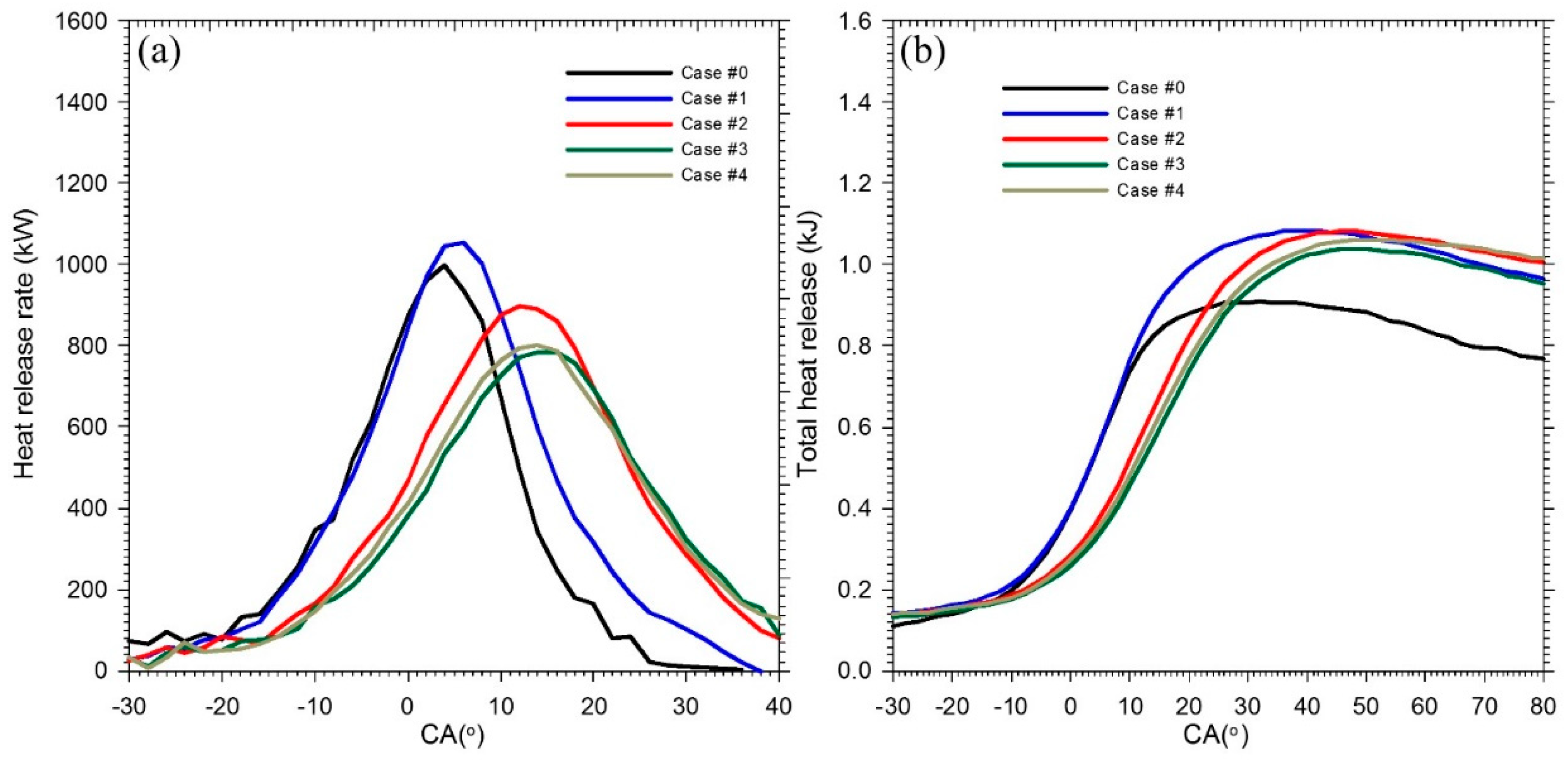
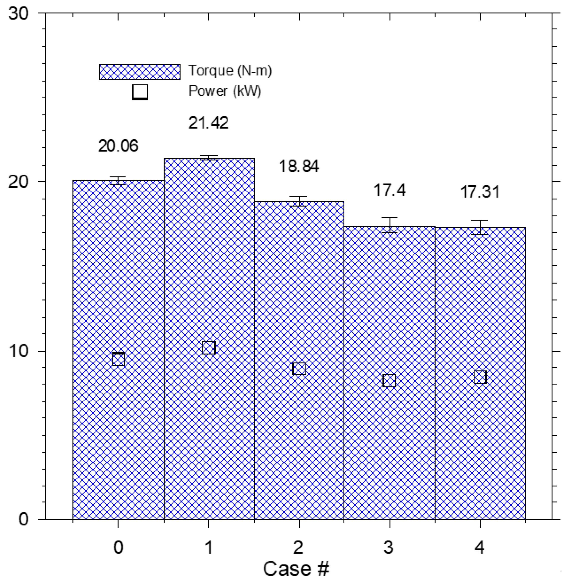
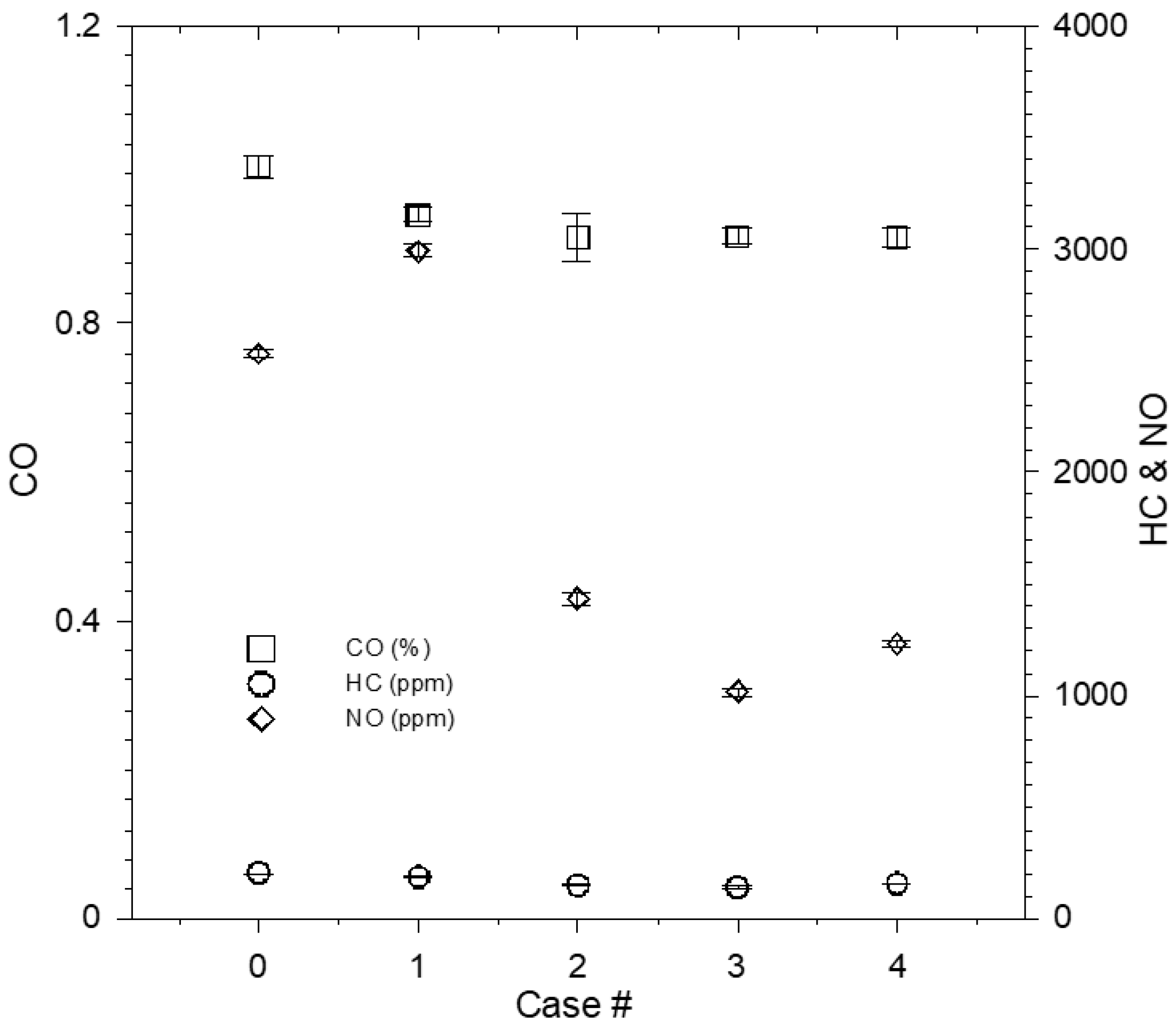
3.2. Effect of the Expansion to Compression Ratio

BSFC is an important engine parameter and allows for the comparison of different engines. It is the ratio of fuel consumption to the power produced. The real-time measured BSFC is calculated based on measured fuel consumption and work output measured by the dyno. For numerical simulation, the BSFC can be obtained in calculation results. The theoretically calculated BSFC as well as the measured results with error bars were compared and shown in Figure 4. Note that the brake specific fuel consumption is defined as the ratio of the fuel consumption rate to the power produced. According to theoretical calculations, the lowest BSFC value occurred for case 1. The measured results showed a similar trend to the theoretical calculations. For measured results, the maximum fluctuation was 7.9% for case 3. Generally, the default setting of a commercial engine does not have the best BSFC. Indeed, as the ECR was increased, the BSFC was also affectedly reduced for short stroke engines. The simultaneous heat release rate, which is defined in Equation (3), describes the relationship between crank angle and the various valve settings.
q ˙ = γ γ 1 p d V d t + 1 γ 1 V d p d t + d Q w d t
  Q = q ˙ d t
Where q ˙ is the heat release rate (HRR), d Q w d t is the convective heat-transfer rate to the combustion chamber walls, γ is the ratio of specific heats ( C p / C v ), C v is the constant volume specific heat capacity (kJ/kg·K), C p is the constant pressure specific heat capacity (kJ/kg·K), and Q is the total heat release (THR, kw). In addition, it has been known that γ primarily depends on the temperature and can be shown in Equation (5) [27].
γ = 1.35 6 × 10 5 T + 1 × 10 8 T 2
The heat release rate and the total heat release rate during the single cycle of engine operation are shown in Figure 5. Higher heat release rate induces higher chamber pressure and greater force acting on the piston to produce higher power and torque. As shown in Figure 5a, the maximum heat release rate occurred in case 1. The accumulated heat release profile, which was calculated via Equation (4), is shown in Figure 5b. Despite the accumulated heat release in case 2 being similar to that in case 1, the peak in simultaneous heat release was delayed due to lower combustion flame speed as the effective expansion stroke was increased. Note that the ignition time was fixed at 315°. The power and torque corresponding to different valve timing settings are shown in Figure 6 The results show that the maximum values of both torque and power occurred in case 1 reached 21.42 N-m and 10.17 kW, respectively. The torque and power output decreased as the ECR was increased. The emissions, including CO, HC, and NO, are shown in Figure 7 The CO and HC emissions monotonically decreased as the expansion to compression ratio increased. However, the NO reached its maximum value in case 1. The intake and exhaust valve settings in case 1 showed relatively better performance, and hence were used to further study the application of bioethanol/gasoline blended fuel.
From the analysis of Figure 4, Figure 5, Figure 6 and Figure 7, we can see that the engine running on case 1 conditions had the lowest BSFC value, which also indicates that the engine had the best combustion efficiency under the same fuel injection amount. This can be verified by Figure 5a for case 1. After the compression at TDC (CA 4°), the instantaneous heat release rate (HRR) reached the highest value and was significantly higher than the other cases. However, for the condition of case 1, NO generation was also the highest one, which was due to the high temperature of fuel burning in the combustion process. This result also agrees with the results presented in Figure 5a,b. Furthermore, it can be seen from Figure 4 that when the ECR was near 1.0, the internal exhaust gas recirculation value (I-EGR) of the engine can be estimated. The increase in I-EGR caused deterioration of the internal combustion efficiency of the engine, as can be seen from Figure 5, and the highest value of HRR also decreased that affected the torque output. This result also reflected in the increase of the BSFC values of cases 2, 3, and 4 when increasing the ECR values.

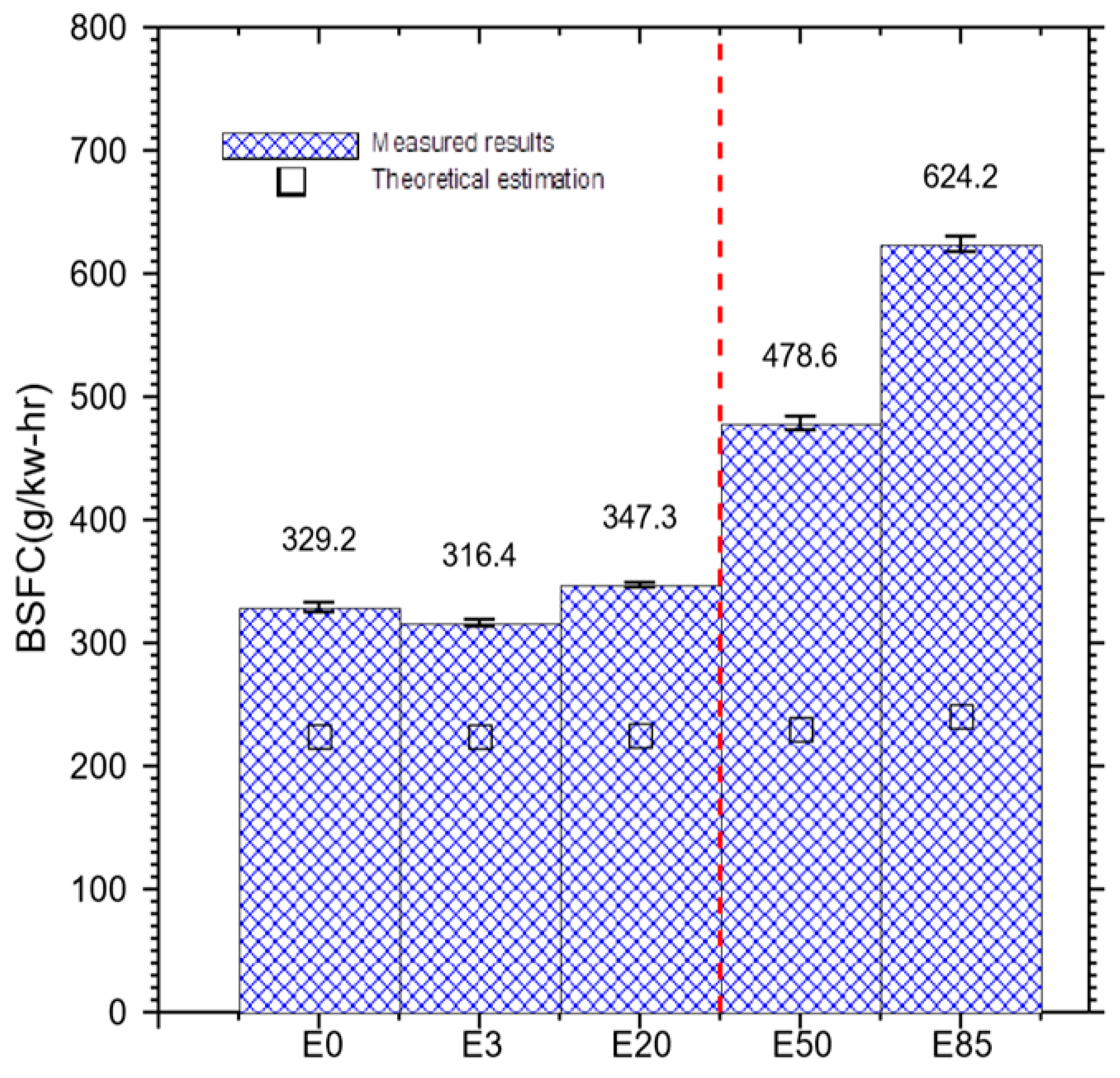
3.3. Bioethanol Application

Figure 8 is the corresponding BSFC trend diagram obtained by experimental measurement data and 1D numerical calculation using commercial code, GT-POWER, wherein the hollow square symbols in the figure indicate the numerical values obtained by numerical calculation. The theoretically estimated BSFC values for E3, E20, E50, and E85 demonstrate no significant change when compared to regular gasoline. The measured BSFC for E3 shows the lowest value compared to regular gasoline (E0) and other bioethenols E20, E50, and E85. It is interesting to note that with the same ignition time (315°), it was not easy to maintain steady engine operation and reach 4500 rpm using E50 and E85. Hence, the ignition time was tuned earlier by shifting to 302°. The measured results are also plotted in Figure 8 and divided by a red dashed line. As the composition of ethanol in the blended fuel was increased, the BSFC values also increased. The torque and power output for different blended fuels are shown in Figure 9. The results for E3 and E20 show an improvement in torque and power when compared to regular gasoline fuel. The superior performance of ethanol blended fuel can be attributed to the higher-octane number and the improvement in engine volumetric efficiency due to higher latent heat of ethanol. However, a higher composition of ethanol in the blended fuel induced not only a lower heating value but also lower flame propagation speed. Therefore, the performance of E50 and E85 was worse than that of regular gasoline and produced higher HC and CO emissions, as shown in Figure 10. The CO and HC emissions increased dramatically due to incomplete combustion. The various NO emissions are shown in Figure 9 and generally appeared to be lower in ethanol blended fuels compared to regular gasoline. However, E3 produced higher NO emissions than regular gasoline.

3.4. Discussion

It has been well known that the Atkinson cycle is a method to achieve fuel economy for four stroke IC engine by controlling valve timing. Different to the vehicle applications of long stroke engine, a short stroke is more suitable for single cylinder engines and provides the advantage of higher possible engine speed with lower crank stress for motorcycle applications. In the present study, the engine speed was maintained in cruise mode and at 4500 rpm. By slightly modifying the valve timing settings, the performance and brake specific fuel consumption can be improved, at the cost, however, of increased NO emissions. The results also reveal that the brake specific fuel consumption cannot be well optimized by increasing the ECR to achieve an Atkinson cycle. In the present study, the ECR was tuned by controlling valve timing and induced a lower effective compression ratio. Due to relative shorter compression stroke as compared with the expansion stroke of the engine, more net mechanical work output can be obtained which means higher efficacy. However, a short stroke engine with a high bore/stroke ratio leads to lower thermal efficiency due to heat loss through the surfaces of the piston and cylinder heads. Therefore, thermal loss can increase as the effective expansion stroke is extended. Moreover, a fast combustion process needs to be achieved in short stroke engines. However, with a high bore/stroke ratio, the inhomogeneity of the fuel and air mixing during the combustion process results in higher emissions and lower engine performance. As the effective compression stroke is relatively short, the pressure of the fuel/air mixture prior to ignition decreases, resulting in lower flame speed and incomplete combustion, as shown in Figure 5 and Figure 7. Due to the intrinsic properties of short stroke engines, a greater amount of fuel needs to be consumed to maintain the same engine speed if the ECR is increased further.
In addition, the heating value of ethanol was less than that of gasoline resulting in a lower flame propagation speed. The present results reveal that the ignition time needs to occur earlier to maintain steady operation in short stroke engines. In addition, CO and HC emissions increase dramatically due to incomplete combustion. Due to the intrinsic properties of ethanol/gasoline blended fuel, in order to maintain a constant engine speed with the same throttle position, more fuel is needed as the composition of ethanol in the fuel is increased.

4. Conclusions

In the present study, the effect of valve timing on engine performance was theoretically and experimentally investigated. In addition, the application of various ethanol/gasoline blended fuel (E3, E20 E50, and E85) was also studied, with a specific focus on engine performance, fuel consumption and emissions. The present study provides significant results relating to the effect of the expansion to compression ratio on the short stroke engine, and the feasibility of applying ethanol/gasoline blended fuel to a short stroke engine, i.e.,
  • With appropriate intake and exhaust valve settings, fuel consumption and engine performance can be well adjusted. However, better engine performance results in higher NO emissions. Due to the innate properties of short stroke engine, only a few operation ranges can be adjusted.
  • Short stroke engines cannot achieve high Atkinson cycle efficiency due to lower compression pressure, which induces a lower flame propagation speed and heat loss through the surfaces of the piston and cylinder head in the combustion chamber.
  • From the experimental and numerical results, we see that as the engine ECR value increases to achieve an Atkinson cycle, the engine torque, power rate, and NO emissions will all decrease, and the amount of CO and HC will increase for short stroke engines due to increased I-EGR.
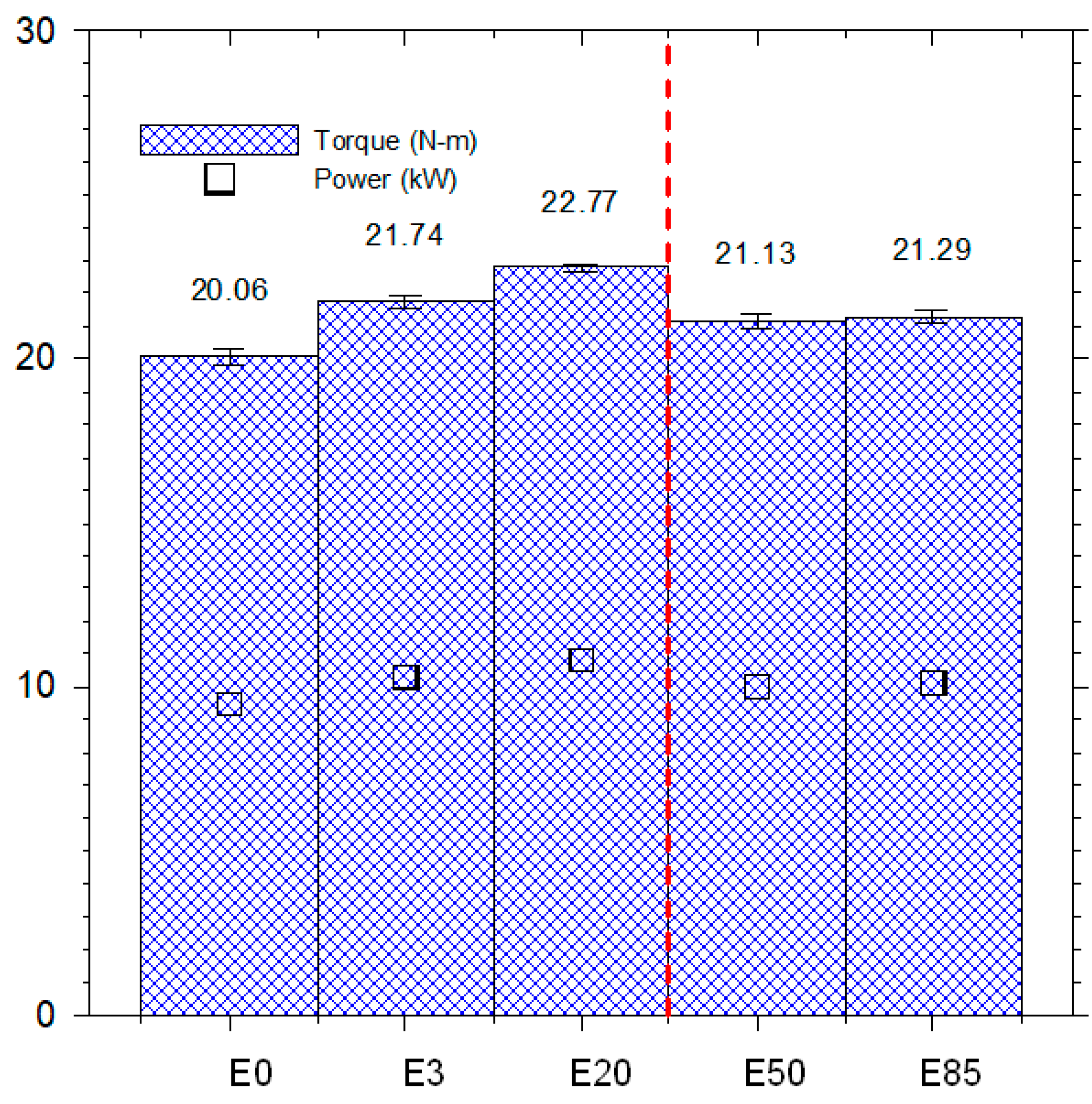
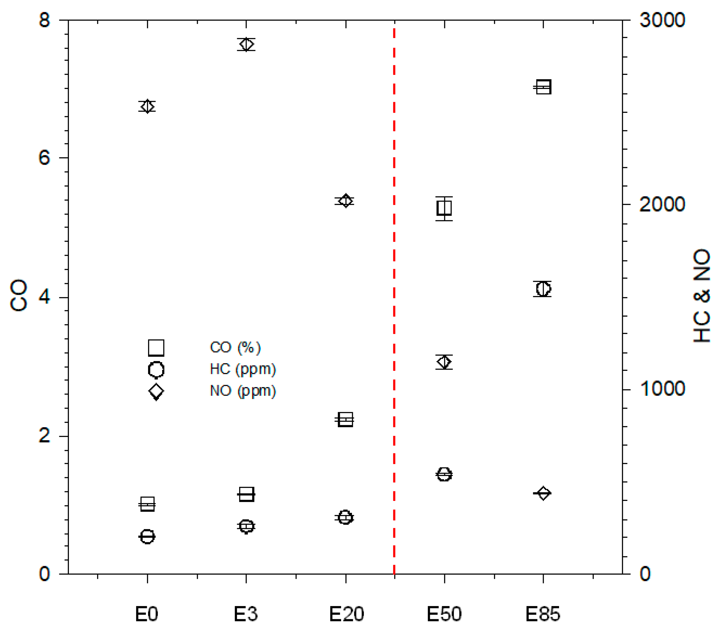
  • It is necessary to vary the ignition time for fuel containing higher ethanol composition to overcome the lower flame propagation speed induced by the lower heating value of the fuel. A higher composition of ethanol in the blended fuel induces lower engine performance and higher emissions of CO and HC, while NO emissions are reduced.
The fuel consumption as well as engine performance of short stroke motorcycle engines can be improved by correctly setting the valve controls. In addition, ethanol/gasoline blended fuel can be used up to a composition of 20% without engine modification. The ignition time needs to be adjusted in fuel with higher compositions of blended ethanol. The fuel economy of a short stroke engine cannot be sharply improved using an Atkinson cycle, but CO2 emissions can be reduced using ethanol/gasoline blended fuel. In the present study, the discrepancies between measured and calculated results can be found. Due to the limitation of 1-D simulation and the assumptions of the model, the combustion process cannot be exactly evaluated using 1-D numerical simulation. Hence, further study using 3-D numerical simulation coupled with more detailed chemical mechanism is recommended.

Author Contributions

K.-H.C. was the main author of this manuscript and contributed to the experiment design, data collection, theoretical analysis, and manuscript preparation. Y.-C.C. provided technical guidance for research work and supervised the whole project.

Acknowledgments

This research was supported by the Ministry of Science and Technology, Taiwan, R.O.C. under Grant no. MOST 105-2221-E-006 -107 -MY3 and MOST 104- 2221-E-244-008.

Conflicts of Interest

The authors declare no conflict of interest.

References

  1. Statistics Inquiry, Ministry of Transportation and Communications, Taiwan. Available online: http://stat.motc.gov.tw (accessed on 20 June 2016).
  2. Atkinson, J. Gas Engine. U.S. Patent 367496A.
  3. Heywood, J. Internal Combustion Engine Fundamentals; McGraw-Hill: New York, NY, USA, 1997. [Google Scholar]
  4. Ferrey, P.; Miehe, Y.; Constensou, C.; Collee, V. Potential of a variable compression ratio gasoline SI engine with very high expansion ratio and variable valve actuation. SAE Int. J. Engines 2014, 7, 468–487. [Google Scholar] [CrossRef]
  5. Chen, L.; Lin, J.; Sun, F.; Wu, C. Efficiency of an Atkinson engine at maximum power density. Energy Convers. Manag. 1998, 39, 337–341. [Google Scholar] [CrossRef]
  6. Wang, P.Y.; Hou, S.S. Performance analysis and comparison of an Atkinson cycle coupled to variable temperature heat reservoirs under maximum power and maximum power density conditions. Energy Convers. Manag. 2005, 46, 2637–2655. [Google Scholar] [CrossRef]
  7. Hou, S.S. Comparison of performances of air standard Atkinson and Otto cycles with heat transfer considerations. Energy Convers. Manag. 2007, 48, 1683–1690. [Google Scholar] [CrossRef]
  8. Boretti, A.; Scalzo, J. Novel Crankshaft Mechanism and Regenerative Braking System to Improve the Fuel Economy of Light Duty Vehicles and Passenger Cars. SAE Int. J. Passeng. Cars—Mech. Syst. 2012, 5, 1177–1193. [Google Scholar] [CrossRef]
  9. Benajes, J.; Serrano, J.R.; Molina, S.; Novella, R. Potential of Atkinson cycle combined with EGR for pollutant control in a HD diesel engine. Energy Convers. Manag. 2009, 50, 174–183. [Google Scholar] [CrossRef]
  10. Čuček, L.; Varbanov, P.S.; Klemeš, J.J.; Kravanja, Z. A review of footprint analysis tools for monitoring impacts on sustainability. Energy 2012, 44, 135–145. [Google Scholar] [CrossRef]
  11. Mussatto, S.I.; Dragone, G.; Guimarães, P.M.; Silva, J.P.; Carneiro, L.M.; Roberto, I.C. Technological trends, global market, and challenges of bio-ethanol production. Biotechnol. Adv. 2010, 28, 817–830. [Google Scholar] [CrossRef] [PubMed] [Green Version]
  12. Kumar, S.; Singh, N.; Prasad, R. Anhydrous ethanol: A renewable source of energy. Renew. Sustain. Energy Rev. 2010, 14, 1830–1844. [Google Scholar] [CrossRef]
  13. Niven, R.K. Ethanol in gasoline: Environmental impacts and sustainability review article. Renew. Sustain. Energy Rev. 2005, 9, 535–555. [Google Scholar] [CrossRef]
  14. Agarwal, A.K. Biofuels (alcohols and biodiesel) applications as fuels for internal combustion engines. Prog. Energy Combust. Sci. 2007, 33, 233–271. [Google Scholar] [CrossRef]
  15. Stein, R.A.; Anderson, J.E.; Wallington, T.J. An overview of the effects of ethanol-gasoline blends on SI engine performance, fuel efficiency, and emissions. SAE Intern. Engines 2013, 6, 470–487. [Google Scholar] [CrossRef]
  16. Thangavelu, S.K.; Ahmed, A.S.; Ani, F.N. Review on bioethanol as alternative fuel for spark ignition engines. Renew. Sustain. Energy Rev. 2016, 56, 820–835. [Google Scholar] [CrossRef] [Green Version]
  17. Thompson, P.B. The agricultural ethics of biofuels: The food vs. fuel debate. Agriculture 2012, 2, 339–358. [Google Scholar] [CrossRef]
  18. Chen, W.H.; Tu, Y.J.; Sheen, H.K. Impact of dilute acid pretreatment on the structure of bagasse for producing bioethanol. Int. J. Energy Res. 2010, 34, 265–274. [Google Scholar] [CrossRef]
  19. Chen, W.H.; Tu, Y.J.; Sheen, H.K. Disruption of sugarcane bagasse lignocellulosic structure by means of dilute sulfuric acid with microwave-assisted heating. Appl. Energy 2011, 88, 2726–2734. [Google Scholar] [CrossRef]
  20. Limayem, A.; Ricke, S.C. Lignocellulosic biomass for bioethanol production: Current perspectives, potential issues and future prospects. Prog. Energy Combust. Sci. 2012, 38, 449–467. [Google Scholar] [CrossRef]
  21. Kun-Balog, A.; Sztankó, K.; Józa, V. Pollutant emission of gaseous and liquid aqueous bioethanol combustion in swirl burners. Energy Convers. Manag. 2017, 149, 896–903. [Google Scholar] [CrossRef]
  22. ANSI/ASME, Part 10, Flue and Exhaust Gas Analyses; Performance Test Code PTC 19.10; American Society of Mechanical Engineers: New York, NY, USA, 1981.
  23. Gamma Technologies. Available online: https://www.gtisoft.com/ (accessed on 20 June 2016).
  24. Constensou, C.; Collee, V. VCR-VVA-High Expansion Ratio, a Very Effective Way to Miller-Atkinson Cycle. In Proceedings of the SAE 2016 World Congress and Exhibition, Detroit, MI, USA, 12–14 April 2016. [Google Scholar]
  25. Andrews, G.E.; Bradley, D. The burning velocity of methan-air mixtures. Combust. Flame 1972, 19, 275–288. [Google Scholar] [CrossRef]
  26. Bayraktar, H. Experimental and theoretical investigation of using gasoline-ethanol blends in spark-ignition engines. Renew. Energy 2005, 30, 1733–1747. [Google Scholar] [CrossRef]
  27. Brunt, M.F.J.; Platts, K.C. Calculation of Heat Release in Direct Injection Diesel Engine. J. Engines 1999, 108, 161–175. [Google Scholar] [CrossRef]
Figure 1. p-v and T-s diagram of Otto cycle and Atkinson cycle.
Energies 12 00759 g001
Figure 2. Single-cylinder engine mode.
Energies 12 00759 g002
Figure 3. Single-cylinder engine model.
Energies 12 00759 g003
Figure 4. Comparison of measured and theoretically estimated brake specific fuel consumption (BSFC) for different valve settings.
Energies 12 00759 g004
Figure 5. (a) Heat release rate; (b) Total heat release for different valve settings.
Energies 12 00759 g005
Figure 6. Power and torque output for different valve settings.
Energies 12 00759 g006
Figure 7. Emissions of CO, HC, and NO for different valve settings.
Energies 12 00759 g007
Figure 8. Estimated and measured BSFC for ethanol/gasoline blended fuel.
Energies 12 00759 g008
Figure 9. Power (KW) / torque(N-m) t for ethanol/gasoline blended fuel.
Energies 12 00759 g009
Figure 10. Emissions of CO, HC, and NO for ethanol/gasoline blended fuel.
Energies 12 00759 g010
Table 1. Test engine specification.
DesignSpecification
Engine typeSpark ignition engine
CoolingLiquid cooled
no. of cylinders1
Configuration Port fuel injection
Bore92 mm
Stroke75 mm
Compression ratio10.6:1
displacement498.5 cc
Cylinder head4 valve, DOHC
Table 2. The measurement ranges and uncertainties for major apparatus.
ApparatusModelrangeuncertainty
MEXA-584l (gas analyzer)Co0% to 10% vol±0.01%
HC0 to 20,000 ppm±3.3 ppm
CO20% to 20% vol±0.17%
NO0 to 5000 ppm±0.5 ppm
O20% to 25%±0.5%
Teledyne (air mass flow meter)HFM-200 LFE0 to 200 LPM±0.5%
Siemens FC (fuel mass flow meter)MASSFLO 41000 to 30 kg/h±0.1%
Optrand (pressure tranducer)D322D6-SO0 to 200 bar±1%
Bosch LSU (AFR sensor)72009 to 41±2%
Table 3. Empirical coefficients for laminar flame speed.
FuelZW(cm/s)ηξαβ
C8H18146.58−0.3264.481.56−0.22
C2H5OH146.50.256.341.75 0.17 / ψ
C8H18 + C2H5OH1 + 0.07 X E 0.35 46.58−0.3264.481.56 + 0.23 X E 0.35 X G β G + X E β E
Table 4. Initial conditions for simulation settings.
Engine speed (rpm)4500
Ambient pressure (Bar)1
Ambient temperature (K)298
Exhaust initial pressure (Bar)1
Exhaust initial temp. (K)1120
Exhaust initial wall temp. (K)1000
Intake pressure (Bar)1
Intake temp. (K)300.15
Lamda (λ)1.0
Intake cam lift (cm)0.83
Exhaust cam lift (cm)0.82
Table 5. Timing of valves.
Case #Intake Valve OpenIntake Valve CloseExhaust Valve OpenExhaust Valve CloseValve OverlapExpansion/Compression
0314−14686−324820.59
1331−12892−318720.72
2336−124120−290940.97
3336−124140−2701141.13
4336−124150−2601241.21
unit: degree

