Abstract
This paper presents the effectiveness of the interior search algorithm in economic power scheduling of a grid-tied DC microgrid with renewable generation (wind and photovoltaic) and battery energy storage. The study presents the modelling and simulation of various DC/DC converters for tracking maximum power from wind and photovoltaic sources and the bidirectional power flow of battery energy storage. The DC microgrid and its controllers were modelled and simulated in MATLAB/Simulink. The generating units were dispatched economically using the interior search algorithm with the objective to minimize the operating cost of the microgrid. The simulated results verify the effectiveness of the interior search algorithm as the daily cost of microgrid operation was reduced by 11.25%.
1. Introduction
The growing interest in renewable energy sources has increased the popularity of microgrids. A microgrid is primarily a self-sufficient, small grid which combines conventional generation with renewable energy sources (RESs) and battery energy storage (BES) [1]. Microgrids can be connected with the main grid to exchange power, or it can operate in an islanded mode in case of a main grid failure or when operating in a remote area. The main advantage of a microgrid is its reliability and intelligent supply of power to local loads [2].
Initially, AC microgrids were the main focus of research, as traditional power systems are based on AC technology. Besides the ease of transforming AC from one voltage to another, most of the loads in our households and factories were of an AC nature [3,4]. However, with the recent developments in the field of advanced power electronics, most of the loads are of a DC nature and were thus connected to the utility by an AC/DC converter [5]. The main load in the commercial and residential sector (i.e., computers, lighting, chargers, etc.) also employs AC/DC conversion. Additionally, the recent development in electric vehicles also relies on the AC/DC conversion for integration with the grid [6,7]. These converters reduce the overall reliability and efficiency of the system and some of these can be replaced with efficient DC/DC converters. Moreover, DC microgrids also have no frequency stability issues and do not require compensation for reactive power as AC microgrids do. This makes it a better choice for distributed generation systems [8]. Therefore, the DC microgrid is gaining popularity in the research community, due to its higher reliability, efficiency, controllability, good power quality, and the ease with which renewable energy sources can be integrated [9].
The main challenge in operating a microgrid is maintaining the power balance between the weather-dependent intermittent RESs and power demand while minimizing the operating cost. Economic and reliable operation of a microgrid is based on suitable designs of power converters and associated controllers for various RESs and BESs, as well as the economic scheduling of power [10].
Energy management systems (EMSs) control the generation of each RES and power flow in the microgrid. Based on the optimal cost of operation, the EMS generates reference power values for various RESs, BESs, and power exchanges with the grid [11,12]. This economic power scheduling has been the focus of many previous studies [13,14,15]. However, in these studies [7,8,9], cost minimization was not taken into consideration. One work [16] considers cost minimization, but ignores the effects of electricity market prices. Most of the previous studies regarding microgrids does not detail the design of various power converters and their respective controllers.
Various optimization techniques have been used for solving the cost minimization problem. These include mixed integer linear programming (MILP) [17], game theory [18], and heuristic optimization algorithms [19]. Heuristic optimization techniques have been effectively used for solving complex optimization problems, due to their flexibility, computational efficiency, and accuracy. Among the various algorithms used for cost minimization, such as particle swarm optimization (PSO), the simulated annealing algorithm (SA), genetic algorithm (GA), and interior search algorithm (ISA) [20], the ISA performs the best [21].
This study presents a grid-tied DC microgrid with wind and photovoltaic (PV) as RESs and a BES. The modelling of various DC/DC converters for an RES and a BES are also presented, along with the modelling and control of a voltage source converter (VSC) for interfacing the DC microgrid with the utility grid. Additionally, the optimal power flow of the microgrid was calculated with ISA 24-h in advance in hourly forecasts. The paper is structured as follows. Section 2 describes the microgrid structure, modelling and controller design of various DC/DC converters. Section 3 explains the implementation of ISA for optimal power scheduling of the DC microgrid. The viability of various controllers, converters, ISA, and the overall DC microgrid is presented in Section 4. Finally, the conclusion of the study is presented in Section 5.
2. Structure of DC Microgrid
The overall structure of the proposed grid-tied DC microgrid is shown in Figure 1. The RESs connected with the microgrid were a direct-drive permanent magnet synchronous generator (PMSG) wind turbine and PV. The output voltage of the PMSG was rectified to DC voltage using an uncontrolled rectifier, and a DC/DC boost converter was employed to step-up the voltage to the DC bus voltage level while implementing the maximum power point tracking (MPPT) algorithm. Similarly, for the PV system, a DC/DC boost converter was employed to implement the MPPT and to step-up the DC voltage to the DC bus voltage level. A bidirectional DC/DC converter was used for BES to allow for the bidirectional flow of power expected in such systems.

Figure 1.
Overall structure of the DC microgrid.
2.1. Direct-Drive PMSG Wind Turbine
A wind turbine generates mechanical power by converting the kinetic energy of wind. This mechanical power generated by the wind turbine is calculated as [22]
where is the air density and is equal to 1.225 kg/m3, is the wind turbine blades swept area, is the power coefficient, and is the wind speed. is computed from the pitch angle and the tip speed ratio . is given as
where is the rotational speed of the wind turbine rotor and is the length of the turbine blades. It is evident from the above discussion that, for a specific wind turbine design and wind speed, all other variables remain constant and, hence, the output mechanical power from the wind turbine varies with the rotational speed of the rotor ().
Below the rated maximum power for the wind turbine, was varied to operate the wind turbine at maximum efficiency. Once the wind speed reached nominal speed, the output power of the wind turbine was limited to the rated power to avoid any stress on the wind turbine. Here, pitch regulation was employed, which changes the angle of attack of the blade (also known as pitch angle ), to maintain the rated power. Hence, depending on the wind speed, the wind turbine operates in three power regions: (1) Below the cut-in wind speed, the wind turbine is stalled and hence generates no power; (2) above cut-in and nominal wind speeds, the MPPT controller varies the rotational speed to maximize efficiency, and (3) above the nominal wind speed, the pitch controller operates the wind turbine in constant power mode. The wind turbine overall control structure is depicted in Figure 2.

Figure 2.
Overall control structure of the wind energy system.
The wind turbine was directly connected to a PMSG generator and, hence, the term direct-drive is used. The direct-drive system eliminates the need for the gearbox system, thus making the system more reliable with easier operation and maintenance. The mechanical and electrical torques for a PMSG are calculated as
where is the mechanical power input; and are the mechanical and electrical angular frequencies, respectively; is the number of poles; and is the output electrical power of the PMSG.
The dynamic equation for a PMSG can be calculated as
where is the coefficient of friction and denotes the rotational inertia of a PMSG. From the above equation, it is clear that the generator speed varies, due to the difference between electrical and mechanical torques. Therefore, changing the electrical torque of the PMSG changes the speed of the generator. This was achieved by controlling the duty cycle of the DC/DC boost converter, as shown in Figure 2.
2.2. PV System
The overall control structure of the PV generation system is depicted in Figure 3. The PV array was connected to the DC microgrid through a DC/DC boost converter. The DC/DC boost converter was employed to raise the voltage of the PV system to the DC voltage level of the microgrid while also implementing the MPPT algorithm.

Figure 3.
Overall control structure of the PV system.
The inductor current of a DC/DC boost converter was the controllable variable. The output and input voltage of the DC/DC boost converter could be controlled by controlling inductor current. However, the output voltage of the DC/DC boost converter was the DC bus voltage, which was controlled by the VSC. Therefore, the input voltage (which is the voltage of the PV array) of the DC/DC boost converter was controlled to achieve MPPT. In continuous conduction mode, the input voltage of the DC/DC boost converter can be calculated as
From the above equation, it is clear that varying the duty cycle () of the converter varies the input voltage (), as is kept constant by the VSC.
For simplicity, the Perturb and Observe (P&O) algorithm was employed for MPPT in this study. In this algorithm, the input voltage of the PV array is increased by a small amount. If this results in an incremental power increase, the input voltage is further increased in that direction until the incremental increase in power stops. Figure 4 summarizes the above discussion in a flowchart illustrating the P&O–MPPT algorithm.

Figure 4.
Perturb and Observe (P&O) algorithm with MPPT flowchart.
2.3. Battery Energy Storage
The recent developments in battery technology have generated a lot of attention for their applications in microgrids [23]. The overall structure of the battery energy storage (BES) used in this study is depicted in Figure 5.

Figure 5.
Overall structure of the battery energy storage (BES).
A DC/DC bidirectional converter was used for interfacing the battery with the DC microgrid. A DC/DC bidirectional converter is essentially a buck-boost converter. The converter operates in boost mode when the battery is to be discharged and in buck mode when the battery is to be charged.
Two PI controllers were used for each mode of operation, i.e., buck and boost mode. The PI controllers regulated the current of the converter to ensure reference tracking of power. The output of the PI converters was passed on to a logic controller. This logic controller decided whether to operate the converter in buck or boost mode, while also ensuring that the state of charge (SOC) of the battery remained within 10 and 90%.
2.4. Grid interfacing Voltage Source Converter (VSC)
A voltage source converter (VSC) is a self-commutated converter constructed with semiconductor switches with turn-off capabilities, such as insulated gate bipolar transistors (IGBTs) [24]. In this study, a typical two-level three-phase converter was considered, due to its reliability and simplicity. The converter was tied to the grid using phase reactors and transformers. The phase reactors were employed for controlling the flow of power via current regulation through them and for filtering high frequency harmonic components of the output currents. The overall structure of the grid interfacing VSC is depicted in Figure 6.

Figure 6.
Overall structure of the voltage source converter (VSC).
The controller for the grid interfacing VSC can use either direct power control (DPC) or voltage-oriented control (VOC). In this study, VOC was utilized, due to its lower energy losses and current distortion relative to DPC [25]. VOC was essentially a dual-loop controller, with an outer slower DC voltage control loop and an inner faster current control loop. The current control loop was implemented in the dq rotating reference frame. The phase locked loop was utilized to extract the frequency and phase angles from grid voltages [26]. The phase angle thus obtained was used to transform the measured currents and voltages of VSC from the abc-frame to dq-frame. The dynamic equation of the VSC can thus be deduced as
where represents grid voltage, represents the VSC output current, represents the VSC terminal voltage, and represents the coupling term. Considering the above dynamic equations of the VSC, the inner current loop is derived, as shown in Figure 7.
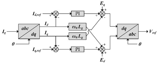
Figure 7.
Inner control loop of the VSC.
To obtain the unity power factor, the d-axis was aligned with the grid voltage. Thus, the q-axis component is set to zero. The d-axis reference current was generated by the outer control loop for controlling the DC bus voltage. The AC and DC power balance of the VSC was utilized to derive a relationship between the d-axis current and DC bus voltage. This was calculated as
Equations (7a) and (7b) were transformed into the s domain and combined to get the transfer function.
The transfer function of Equation (8) was used to derive the outer control loop for the DC voltage control, as seen in Figure 8.

Figure 8.
Output DC voltage control loop of the VSC.
3. Interior Search Algorithm
Interior search algorithm (ISA) is a metaheuristic optimization algorithm used for solving complex optimization problems. The inspiration for ISA comes from interior design. In interior design, the designer usually starts the design process from the boundaries of the space moving towards the center. The arrangement of any element(s) is changed only if it results in a more attractive view while satisfying the client requirements. Persian designers use a technique called mirror work in which they place mirrors near the most attractive element(s) in a space to emphasize their attractiveness [20].
These same principles of the interior design process could also be applied in optimization. The arrangement of any element(s) was changed only if it resulted in improved fitness value (a more attractive view) while satisfying constraints (client requirements). The mirror work technique can also be employed by placing mirrors near the fittest element(s) (i.e., the most attractive element(s)) in a space to explore the local region.
The objective function used to implement ISA for economic optimal power flow in the case of the DC microgrid is presented in Equation (9). The objective of ISA is to minimize this cost function for a 24-h period with a 1-h time interval.
The main constraint for optimization is the power balance, i.e., the power generated should be equal to the load demand and power sold to the grid. This is calculated as
The boundary conditions for the ISA are the limits of the RESs and the SOC for the battery, which were given as
The output powers of RESs and BES are the elements/state variables used for ISA. The steps taken to implement ISA are as follows.
- The initial population of the state variables () was randomly generated within the boundaries. The value of the objective function and the fitness values were calculated. Here, and represent the population number and iteration number, respectively.
- The elements resulting in the minimum fitness value were called the current global best, represented as .
- Two groups were formed from the remaining elements, and these were called the mirror and composition group. Four random variables ( and ) were generated between 0 and 1. When the elements became part of the mirror group or else they became part of the composition group, where was a tuning parameter [20].
- The elements in the composition group were changed randomly within the lower and upper bounds. This was calculated as
- A mirror was randomly placed between the elements of the mirror group and the current global best. The position of the mirror was given by Equation (16), and the new element thus obtained is represented by Equation (17),
- A local search around the global best was carried out to find a better global best, as shown in Equation (18), where represents a scaling factor given by .
- The fitness values for the old and new elements were calculated. The old element was replaced a by new one if the fitness value of the new element was lesser.
Steps 2 to 7 were repeated until the number of iterations were completed.
4. Simulation and Results
The proposed DC microgrid, modelling of various RESs, the respective DC/DC converters, and the implementation of ISA for economic power scheduling were verified using the simulation. A variable speed direct drive wind turbine with PMSG and a generation capacity of 100 kW was modelled. The blade length of such a wind turbine was 13 m with a swept area of 170 m2. The AC generated by the PMSG was rectified, then a boost converter was used to implement the MPPT algorithm.
The PV panels used in the simulation were SunPower SPR-315E-WHT-D, rated at 315 W. They had an output current of 5.76 A and a 54.7 V output voltage at maximum power point (MPP) at STC (with a radiation measurement of 1000 W/m2 and panel temperature of 25 °C). The complete PV array was built with five modules in series per string and 64 strings in parallel, which formed a PV array of 100 kW with a PV array voltage of 274.5 V.
The battery used in this study had a 100 kWh energy capacity, with an initial SOC of 50%. The depth of discharge (DOD) of the battery was 90%. The nominal battery voltage was 300 V, and the DC bus voltage was 500 V. Therefore, a bidirectional DC/DC converter was used, which operates in buck mode when storing energy and in boost mode when releasing it.
For continuous current flow, the values for the inductors and capacitors of various DC/DC converters were chosen to be greater than the minimum values specified by the reference [27]. This was calculated as
To avoid parasitic elements, due to having a higher frequency and audible noise, a switching frequency of 5 kHz was selected for various converters. A typical two-level VSC was simulated for interfacing the DC microgrid with the utility grid. The objective for the controller of the VSC was to maintain the DC bus voltage at 500 V. The VSC was connected to the 11 kV, 60 Hz utility grid, with a 400 kVA, 260 V/11 kV delta-wye transformer. The values of resistance and inductance for the phase reactor between the VSC and transformer were 1 mΩ and 45 µH, respectively.
The operation and maintenance cost of PV, wind, and BES was assumed to be $0.01/kW. All these values are summarized in Table 1.

Table 1.
DC microgrid system parameters.
The daily electricity tariff for buying and selling electricity from/to the grid is represented in Table 2.
Table 2.
Daily electricity tariff.
To verify the effectiveness of employing ISA for economic power scheduling, the cost function was evaluated for two cases.
4.1. Case 1
The ISA was not employed in this case, but a simple strategy was used. This was to store excess energy generated by the RES in the battery and selling this excess energy to the grid in the next time interval. If the battery was fully charged during the storing period, then the excess energy was sold directly to the grid. The forecasted wind, PV, and load demand data were used to calculate the total cost for that day, which came out to be $62.64. The hourly power schedule for this case is represented in Figure 9a.

Figure 9.
Power schedule (a) without interior search algorithm (ISA) and (b) with ISA.
4.2. Case 2
This case employed ISA for the same forecasted generation and load demand. The total cost for the day came out to be $55.59. This significant reduction in price when compared to the first case validates the usage of ISA. The hourly power scheduled by the ISA is demonstrated in Figure 9b.
The performance of the wind turbine and its associated controller is presented in Figure 10. It is evident from the figure that the controller achieves MPPT, and the constant rated power for wind speeds greater than 13 m/s depict the effective operation of pitch control.

Figure 10.
Performance of the wind energy system.
The battery power was effectively tracking the scheduled power in both the charging and discharging states, as shown in Figure 11. It can also be seen that the SOC of the battery stayed within the specified limits of 10 and 90%, indicating a satisfactory performance by the DC/DC bidirectional converter and its controller.

Figure 11.
Performance of the BES system.
Figure 12 depicts the performance of the PV system and its DC/DC boost converter. The decreased duty cycle of the DC/DC boost converter resulting in an increased PV array voltage indicates that the Perturb and Observe the MPPT algorithm worked effectively.
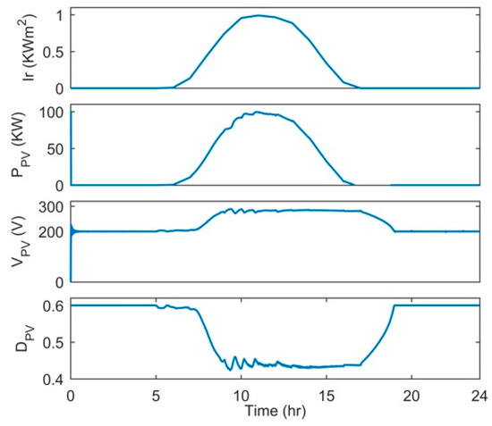
Figure 12.
Performance of the PV system.
The DC bus voltage and the VSC output power is depicted in Figure 13. It is evident that the DC bus voltage remained constant at around 500 V and that the output power of the VSC was tracking the grid power exchange scheduled by the ISA. The DC voltage controller of the VSC also served another purpose. Any misbalance in generation and demand resulted in deviations from the forecast.

Figure 13.
Performance of the voltage source converter (VSC).
5. Conclusions
This paper presented economic power scheduling in a grid-tied DC microgrid with renewable energy sources (RESs) and a battery energy storage (BES) using the interior search algorithm (ISA). The DC/DC boost converters for RESs and DC/DC bidirectional converters for the BES was modelled and simulated in MATLAB/Simulink. The simulated results verified the satisfactory operation of each converter and its associated controller. The DC microgrid was connected with the utility grid through a two-level VSC, with the objective of maintaining the DC bus voltage constant at 500 V. Simulated results showed that the DC bus voltage was held constant at around 500 V, indicating a satisfactory performance by the VSC controller. Finally, the effectiveness of employing ISA for cost minimization was validated by comparing the total costs between the two cases that did and did not employ the ISA. A simulated comparison of the optimized operations using ISA and non-optimized operations resulted in 11.25% of costs being saved, which shows the effectiveness of using ISA in optimizing microgrid operations.
Author Contributions
K.K. conceptualized the study, wrote the paper and, completed the simulation for case studies as the first author. A.K. designed the algorithms. A.B. conceptualized the idea and supervised the project. T.A. curated and analyzed the data. H.A. and A.A. verified the methodology and results. All authors discussed the simulation results and approved the paper for publication.
Funding
We are thankful to USAID and U.S Pakistan Center for Advanced Studies in Energy (USPCAS-E), University of Engineering & Technology Peshawar for funding this research project and paper.
Conflicts of Interest
The authors declare no conflict of interest.
References
- Papadimitriou, C.N.; Zountouridou, E.I.; Hatziargyriou, N.D. Review of hierarchical control in DC microgrids. Electr. Power Syst. Res. 2015, 122, 159–167. [Google Scholar] [CrossRef]
- Elsayed, A.T.; Mohamed, A.A.; Mohammed, O.A. DC microgrids and distribution systems: An overview. Electr. Power Syst. Res. 2015, 119, 407–417. [Google Scholar] [CrossRef]
- Memon, A.A.; Kauhaniemi, K. A critical review of AC Microgrid protection issues and available solutions. Electr. Power Syst. Res. 2015, 129, 23–31. [Google Scholar] [CrossRef]
- Tayab, U.B.; Roslan, M.A.B.; Hwai, L.J.; Kashif, M. A review of droop control techniques for microgrid. Renew. Sustain. Energy Rev. 2017, 76, 717–727. [Google Scholar] [CrossRef]
- Beykverdi, M.; Jalilvand, A.; Ehsan, M.; Beykverdi, M.; Jalilvand, A.; Ehsan, M. Cooperative Energy Management of Hybrid DC Renewable Grid Using Decentralized Control Strategies. Energies 2016, 9, 859. [Google Scholar] [CrossRef]
- Justo, J.J.; Mwasilu, F.; Lee, J.; Jung, J.-W. AC-microgrids versus DC-microgrids with distributed energy resources: A review. Renew. Sustain. Energy Rev. 2013, 24, 387–405. [Google Scholar] [CrossRef]
- Planas, E.; Andreu, J.; Gárate, J.I.; Martínez de Alegría, I.; Ibarra, E. AC and DC technology in microgrids: A review. Renew. Sustain. Energy Rev. 2015, 43, 726–749. [Google Scholar] [CrossRef]
- Yasin, A.; Ashraf, M.; Bhatti, A.; Yasin, A.R.; Ashraf, M.; Bhatti, A.I. Fixed Frequency Sliding Mode Control of Power Converters for Improved Dynamic Response in DC Micro-Grids. Energies 2018, 11, 2799. [Google Scholar] [CrossRef]
- Anand, S.; Fernandes, B.G.; Guerrero, J. Distributed Control to Ensure Proportional Load Sharing and Improve Voltage Regulation in Low-Voltage DC Microgrids. IEEE Trans. Power Electron. 2013, 28, 1900–1913. [Google Scholar] [CrossRef]
- Lin, B.R. Hybrid soft switching converter for DC grid applications. Electr. Power Syst. Res. 2017, 150, 84–95. [Google Scholar] [CrossRef]
- Han, Y.; Chen, W.; Li, Q.; Han, Y.; Chen, W.; Li, Q. Energy Management Strategy Based on Multiple Operating States for a Photovoltaic/Fuel Cell/Energy Storage DC Microgrid. Energies 2017, 10, 136. [Google Scholar] [CrossRef]
- Salas-Puente, R.; Marzal, S.; Gonzalez-Medina, R.; Figueres, E.; Garcera, G.; Salas-Puente, R.; Marzal, S.; Gonzalez-Medina, R.; Figueres, E.; Garcera, G. Practical Analysis and Design of a Battery Management System for a Grid-Connected DC Microgrid for the Reduction of the Tariff Cost and Battery Life Maximization. Energies 2018, 11, 1889. [Google Scholar] [CrossRef]
- García, P.; Torreglosa, J.P.; Fernández, L.M.; Jurado, F.; Langella, R.; Testa, A. Energy management system based on techno-economic optimization for microgrids. Electr. Power Syst. Res. 2016, 131, 49–59. [Google Scholar] [CrossRef]
- Wang, C.; Liu, Y.; Li, X.; Guo, L.; Qiao, L.; Lu, H. Energy management system for stand-alone diesel-wind-biomass microgrid with energy storage system. Energy 2016, 97, 90–104. [Google Scholar] [CrossRef]
- Lee, D.; Cheng, C.-C. Energy savings by energy management systems: A review. Renew. Sustain. Energy Rev. 2016, 56, 760–777. [Google Scholar] [CrossRef]
- Hosseinzadeh, M.; Salmasi, F.R. Robust Optimal Power Management System for a Hybrid AC/DC Micro-Grid. IEEE Trans. Sustain. Energy 2015, 6, 675–687. [Google Scholar] [CrossRef]
- Tenfen, D.; Finardi, E.C. A mixed integer linear programming model for the energy management problem of microgrids. Electr. Power Syst. Res. 2015, 122, 19–28. [Google Scholar] [CrossRef]
- Lo Prete, C.; Hobbs, B.F. A cooperative game theoretic analysis of incentives for microgrids in regulated electricity markets. Appl. Energy 2016, 169, 524–541. [Google Scholar] [CrossRef]
- Almada, J.B.; Leão, R.P.S.; Sampaio, R.F.; Barroso, G.C. A centralized and heuristic approach for energy management of an AC microgrid. Renew. Sustain. Energy Rev. 2016, 60, 1396–1404. [Google Scholar] [CrossRef]
- Gandomi, A.H. Interior search algorithm (ISA): A novel approach for global optimization. ISA Trans. 2014, 53, 1168–1183. [Google Scholar] [CrossRef]
- Rouholamini, M.; Mohammadian, M. Energy management of a grid-tied residential-scale hybrid renewable generation system incorporating fuel cell and electrolyzer. Energy Build. 2015, 102, 406–416. [Google Scholar] [CrossRef]
- Tian, J.; Zhou, D.; Su, C.; Blaabjerg, F.; Chen, Z. Maximum energy yield oriented turbine control in PMSG-based wind farm. J. Eng. 2017, 2017, 2455–2460. [Google Scholar] [CrossRef]
- Divya, K.C.; Østergaard, J. Battery energy storage technology for power systems—An overview. Electr. Power Syst. Res. 2009, 79, 511–520. [Google Scholar] [CrossRef]
- Lacerda, V.A.; Coury, D.V.; Monaro, R.M. LCL filter design for VSC-HVDC systems supplying passive grids. Electr. Power Syst. Res. 2017, 152, 160–167. [Google Scholar] [CrossRef]
- Freire, N.; Estima, J. A Comparative Analysis of PMSG Drives Based on Vector Control and Direct Control Techniques for Wind Turbine Applications. Przeglad Elektrotechniczny 2012, 88, 184–187. [Google Scholar]
- Khazraj, H.; da Silva, F.F.; Bak, C.L.; Golestan, S. Analysis and design of notch filter-based PLLs for grid-connected applications. Electr. Power Syst. Res. 2017, 147, 62–69. [Google Scholar] [CrossRef]
- Muhammad, R.H. Power Electronics: Devices, Circuits, and Applications; Prentice Hall: Upper Saddle River, NJ, USA, 2006; ISBN 0133125904. [Google Scholar]
© 2019 by the authors. Licensee MDPI, Basel, Switzerland. This article is an open access article distributed under the terms and conditions of the Creative Commons Attribution (CC BY) license (http://creativecommons.org/licenses/by/4.0/).