Article

Scaling Method of the Rotating Blade of a Wind Turbine for a Rime Ice Wind Tunnel Test

1
Engineering College, Northeast Agricultural University, Harbin 150030, China
2
Heilongjiang Provincial Key Laboratory of Technology and Equipment for Utilization of Agricultural Renewable Resources in Cold Region, Northeast Agricultural University, Harbin 150030, China
3
College of Science, Northeast Agricultural University, Harbin 150030, China
*
Author to whom correspondence should be addressed.
Energies 2019, 12(4), 627; https://doi.org/10.3390/en12040627
Submission received: 27 December 2018 / Revised: 10 February 2019 / Accepted: 12 February 2019 / Published: 15 February 2019
(This article belongs to the Section A3: Wind, Wave and Tidal Energy)

Abstract

:
In order to research the law of rime ice accretion on different scaling blades surface, a new rime ice scaling method was proposed in this research. According to previous research, there are three kinds of ice types on blade surfaces: rime ice, glaze ice and mixed ice. Under the condition of rime ice, both the freezing fraction and the coefficient of heat transfer between super-cold water droplets and blade are 100%. The heat transfer model of rime ice is simpler than that of glaze ice and mixed ice. In this research, the scaling parameters including flow field, water droplets, temperature, pressure and rotating parameters were defined. The Weber number (We) based on water film thickness as an important parameter was applied in this study. The rotating parameters including rotating speed and radius had been added into the icing scaling method. To verify the effectiveness of the new rime ice scaling method, icing wind tunnel tests were carried out. The NACA0018 airfoil was used for the test blade. Two kinds of scale chord blades were selected, the chord of full-scale blade was 200 mm and of subscale blade was 100 mm. The test temperature was −15 °C. The ice accretion on different scale blades surface were captured by high-speed camera and the icing shapes of different scaling blades were obtained. To quantitatively analyze the similar degree of icing shapes on different scale blades, an evaluation method which included similar degree (Sim) was established based on the typical characteristic parameters proposed by previous research. The results show that the icing shapes of subscale blades are similar to that of full-scale blades. The similar degree is between 75.22% and 93.01%. The icing wind tunnel test indicates that the new rime ice scaling method is an effective method to study the rime ice of large scale rotating blades. This study can be used as a reference for research on anti-icing and de-icing technologies for large-scale HAWTs (Horizontal Axis Wind Turbines).

1. Introduction

Wind energy, as a main kind of green and renewable energy, has been greatly developed in recent years [1,2,3]. To obtain more wind energy and increase the power generation efficiency, the wind farms usually are constructed in high altitude or cold areas [4,5]. However, the wind turbines operating in these areas usually are threatened by ice problems [6,7]. According to the previous research, the ice mainly accretes on the blade surface of wind turbines [8,9,10]. This will affect the aerodynamic and load distribution, which will decrease the power performance and threaten the safety of wind turbines [11,12,13]. Therefore, it is essential to research ice accretion on blade surfaces of wind turbines [14,15]. As early as 1940, Taylor had already researched the possible equipment and technique for experiments on icing on aircraft [16]. In 1946, Langmuir researched the law of water droplet trajectories based on mathematical investigation and the range parameter was proposed [17]. When the super-cold water droplets impact the blade surface, the ice will accrete on it. Because of the huge size of wind turbines, it is impossible to put a real wind turbine into a laboratory for testing. Therefore, the icing scaling method is an effective method to analyze the characteristics of icing on blade surfaces. The icing scaling method was first applied to aircraft icing research [18]. In 1954, model testing in an icing wind tunnel was carried out by Hugger and Englar, and some characteristics of ice were found [19]. In 1967, Jackson conducted a development study on scale models in an icing tunnel to determine the ice caught on a prototype aircraft with particular reference to the Concorde [20]. In 1978, the trajectory scaling method was studied by Ormsbee and Bragg; in this study, some exact similarity parameters including inertia parameter, Froude number (Fr) and the free stream droplet Reynolds number (RU) were confirmed [21]. A systematical expatiation on techniques and facilities used at the ONERA (Office National d’Etudeset de RecherchesAérospatiales) Modane Center for icing tests was completed by Armand [22]. The icing scaling method was called the ONERA method. In 1986, Ruff analyzed the icing scaling equations proposed by previous research, and a lot of work including theory study and experimental tests has been carried out [23]. Because Ruff belongs to the Arnold Engineering Development Center (AEDC), the scaling law developed by Ruff was called the AEDC method. In 1991, Bilanin proposed 18 kinds of non-dimensional groups based on Buckingham theory through previous research [24]. In 1995, Bilanin and Anderson considered that the Constant-Weber-Number should be added to the icing scaling method; verification experiments were carried out in the NASA Lewis Icing Research Tunnel (IRT) [25]. In 1996, Anderson researched the icing scaling method for rime ice, mixed ice and glaze ice [26]. In 2007, Xian Yi proposed that the dynamic pressure should be added to the icing scaling method [27]. Many verification tests based on numerical simulation have been carried out and the results showed that the icing shapes of subscale blades were similar to that of full-scale models. In 2012, Han Yiqiang used the Ruff theory (AEDC) to simulate ice accretion in the subscale blade model of the NREL Phase VI Rotor [28].
This study analyzed the icing scaling methods based on previous studies. The icing scaling method can be classified into rime ice and glaze ice. Under the rime ice conditions, when the super-cold droplets impact the blade surface, the droplets will change to ice immediately. In other words, both the freezing fraction and the coefficient of heat transfer between super-cold water droplets and blade are 100%. Under the glaze ice conditions, the droplets will change to super-cold water film first and then change to glaze ice; the freezing fraction and the coefficient of heat transfer between super-cold water and blade are both less than 100%. Therefore, the heat transfer model under rime ice conditions is relatively simple to establish the rime ice scaling method. To establish the rime ice scaling method on rotating blades, the centrifugal force was confirmed as the rotating parameter. The icing wind tunnel tests were carried out to verify this new rime ice scaling method. For analyzing the similar degree of icing shape on two scale blade surfaces, an evaluation method was established and the similar degree (Sim) was proposed. The results show that the similar degree of icing shape accretion on subscale blade surfaces and full-scale blade surfaces is between 75.22% and 93.01%, which indicates that the icing shapes of the subscale model are similar to those of the full-scale model. This research will lay the foundation for the glaze ice scaling method. The detailed icing scaling theory and evaluation method are as follows.

2. Rime Ice Scaling Method and Test Verification

2.1. Identification of the Scaling Parameters

2.1.1. Geometric Scaling Requirements

For researching the ice accretion on the subscale geometric surface, some geometric scaling requirements should be satisfied as follows: (1) the shape of subscale model should be similar to that of the full-scale model. (2) The other parameters of the two scale models including surface roughness, material and installation angle are the same. The geometric scaling parameter is as follows:
( c ) m = k ( c ) f
where c is the characteristic length, m represents the subscale model, f represents the full-scale model, k is the model scale factor.

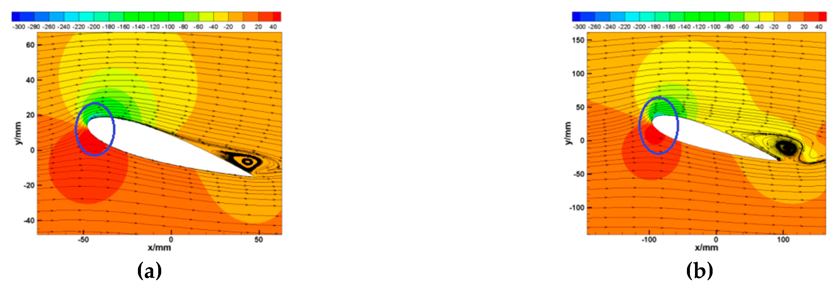
2.1.2. Flow Field Scaling Requirements

According to the icing scaling method established by AEDC and ONERA, the flow field around the subscale model should be similar to that of full-scale model. According to previous research, the rate of wind speed of an operating wind turbine changes from 4 m/s to 25 m/s, which is low-speed flow. According to eighteen icing scaling parameters defined by Bilanin [24], the Reynolds Number (Re) of the subscale model should be the same as the full-scale model. The scaling method defined by Bilanin requires that if the size of subscale model is much smaller than that of full-scale model, the wind speed of the subscale model will be great larger than that of the full-scale model. However, that will make it difficult to select other parameters such as the Weber number (We) and Mach number (Ma). Ruff [23] considered that the ice only forms in the vicinity of the stationary point where the boundary layer is relatively thin, so that the viscous effects are adequately scaled simply by requiring that the bodies are geometrically scaled. Ruff proposed that the test Ma must be greater than that corresponding to Re = 2.0105 and less than Mc. To simplify the flow field scaling requirements, the flow field scaling requirements can be expressed as:
v m = v f
Figure 1 shows the flow field around subscale model and full-scale model by numerical simulation. The velocity of these two scale models is 6 m/s. The results show that the flow field around the leading edge of the subscale is similar to that of the full-scale model. Because the ice mainly accretes on the leading edge, the results show that the flow field scaling requirements is suitable for this study.

2.1.3. Droplet Trajectory Scaling Requirements

In the precondition of satisfying the flow field requirement, the trajectories of the droplets entrained in this flow must also be similar. The droplet trajectory scaling requirement requires that the impingement regions and local collection efficiency between subscale model and full-scale mode is similar. Langmuir and Blodgett [17] found the modified inertia parameter K0 is an important droplet trajectory scaling parameter. It had been verified by Ruff and Xian. K0 is expressed as:
K 0 = ( λ / λ s ) K
where, λ / λ s is defined as the range parameter which is a function of the droplet Reynolds number. It can be expressed as:
λ λ s = 1 Re 0 R e 24 C D R r e l d R r e l
K is the inertia parameter expressed as:
K = 2 9 ρ w r d 2 U μ a c
where Re is the free Reynolds number of droplets, the Rerel is the relative Reynolds number of droplets, ρw is the density of water, rd is the radius of droplets, U is the far field velocity, μa is the viscosity of air, c is the chord length.
The scaling parameter for droplet trajectories is as follows:
( K 0 ) m = ( K 0 ) f

2.1.4. Droplet Impinging Mass Scaling Requirements

In the precondition of satisfying the droplet trajectory requirement, the droplet impingement mass on the blade surface also should be similar, i.e., the total mass of impinging water of the subscale model is similar to that of the full-scale model. It can be expressed as:
( m w ) m = k ( m w ) f
where mw is the mass of impinging water.
Substituting Equation (1) into Equation (7), Equation (7) can be expressed as:
( m w c ) m = ( m w c ) f
The total impinging mass of a unit area on the object surface of the icing time t can be given by following equation:
m w = L W C ( U ) β t
where β is the local impingement efficiency [9].
Substituting Equation (9) into Equation (8), Equation (8) can be expressed as:
( L W C ( U ) β t c ) m = ( L W C ( U ) β t c ) f
The relationship between local collection efficiency and modified inertia parameter can be expressed as follows based on the study of Langmuir and Blodgett [17]:
β = 1.4 ( K 0 0.125 ) 0.84 1 + 1.4 ( K 0 0.125 ) 0.84
In the precondition of satisfying the droplet trajectory requirement, the droplet trajectory requirement will make the local collection efficiency of the subscale similar to that of the full-scale. To simplify the droplet impinging mass scaling requirement, a dimensionless parameter Ac is introduced. It is called the accumulation parameter which can be expressed as:
A c = L W C · U · t · β m w = L W C · U · t · β ρ i c e L
where L is the icing thickness.

2.1.5. Thermodynamic Scaling Requirements

There are complex heat transfer models on object surfaces in the process of icing. The heat transfer model and mass transfer model of the subscale should be similar to those of the full-scale. According to the previous study, the heat transfer model between the subscale and full-scale models is similar under rime ice conditions. Therefore, if the temperature of the subscale model and full-scale model is the same, the thermodynamic requirement will be satisfied. The thermodynamic scaling requirements can be expressed as:
T m = T f

2.1.6. Dynamic Pressure Scaling Requirements

According to previous icing tests, the ice may be thrown off under some conditions. Xian Yi [27] considered that dynamic pressure should be added to the icing scaling method. The dynamic pressure is defined as:
q = 1 2 ρ a V 2
According to the ideal gas equation, Equation (12) can be expressed as:
q = 1 2 p m w n R T V 2
Therefore, the dynamic pressure scaling requirement is:
q m = q f

2.1.7. Liquid Water Dynamic Scaling Requirement

According to the study of Bilanin and Anderson [25], the surface tension of water droplets is a main parameter for the icing scaling method. The Weber number is a relevant parameter of surface tension. According to previous successful test results, Kind and Coauthors considered the Weber number based on water film thickness can be used as a parameter for surface tension. The Weber number based on water film thickness is:
W e w = U δ w , A ρ a σ
where δ w , A is the water film thickness, σ is the surface tension.
Therefore, the liquid water dynamic scaling requirement is:
( W e w ) m = ( W e w ) f

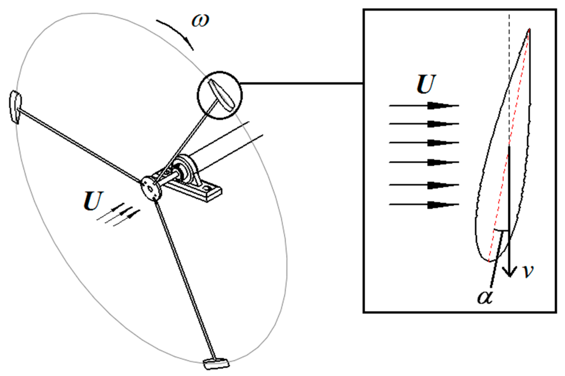
2.1.8. Rotation Parameter Scaling Requirement

A Horizontal Axis Wind Turbine (HAWT) is a typical rotating machine; therefore, the centrifugal force and Coriolis force should be taken into account as the main parameters of the icing scaling method. There are three kinds of parameters including mass, rotation speed and radius of the equations of centrifugal force and Coriolis force. Therefore, the rotating parameter scaling requirement based on the centrifugal force is shown as follows:
σ c = m ω 2 r S cov
where Scov is the icing area.
The rotation parameter scaling requirement is:
( σ C ) m = ( σ C ) f

2.2. Principles for Selecting Test Parameters

According to the above, the principles for the rime ice scaling method are as follows:
L m = k L f
v m = v f
T m = T f
d 0 m = ( L m L f ) 1 2 κ ( p m p f ) κ 2 κ ( T m T f ) κ 2 κ d 0 R
( L W C ) m = ( L W C ) f ( U m U f ) 3 ( ( d 0 ) m ( d 0 ) f ) ( ( ρ a ) m ( ρ a ) f )
P m = P f ( V m V f ) ( T m T f ) 2
t m = t f ( L m L F ) ( U m U f ) 1 ( L W C m L W C f ) 1
ω m = ω f ( β f β m ) 0.5 ( L W C f L W C m ) 0.5 ( L f L m ) 0.5 ( t f t m ) 0.5 ( r f r m ) 0.5 ( ( S cov ) m ( S cov ) f )

2.3. Test Verification

To verify the effective of the new rime ice scaling method, icing wind tunnel tests were carried out. The test parameters were selected based on the new rime ice scaling method. The detailed discussion is as follows.

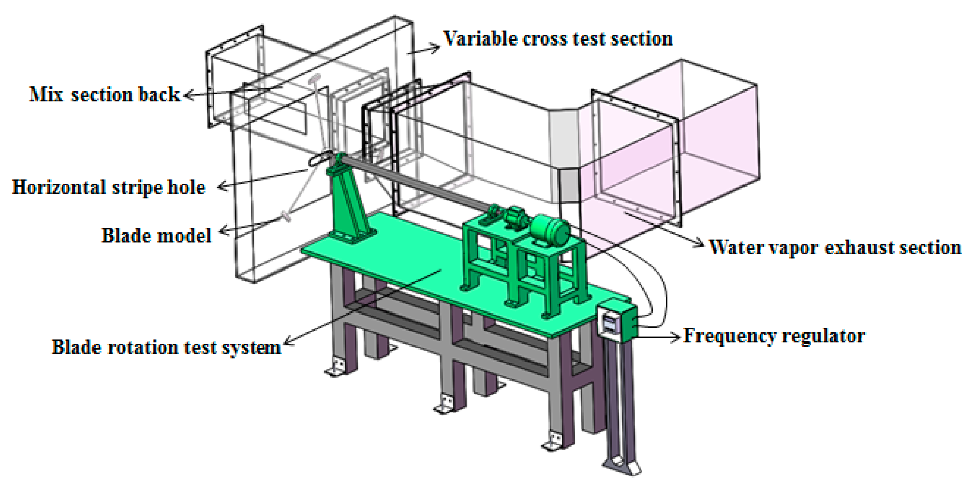
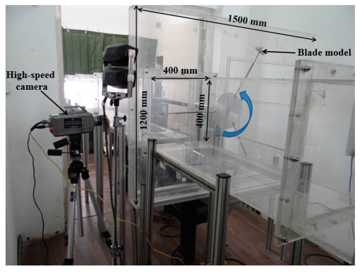
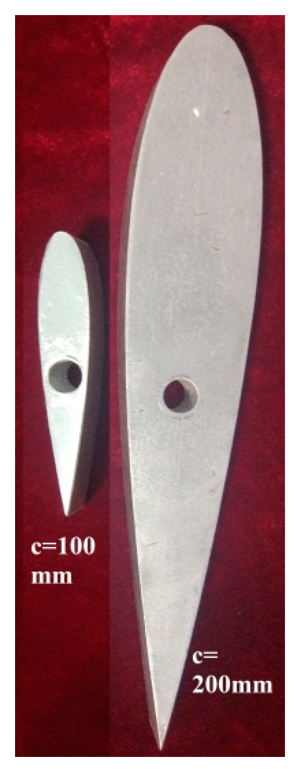
2.3.1. Test Apparatus

Figure 2 shows the schematic diagram of icing wind tunnel experiment system (IWTES) which was designed and constructed in previous research [29]. The main advantage of this system is that low temperature air can be absorbed into tunnel which will greatly reduce the energy consumption and maintenance costs for refrigeration equipment. The icing shapes were recorded by high-speed camera and the icing shapes of different scaling blade models were obtained. The type of high speed camera is Phantom 5.1 which is made by Vision Research Inc. (VRI), USA, and the resolution ration is 1024 × 1024 pixels. Figure 3 shows the 3D diagram of the rotation system. Figure 4 shows the icing shape collection system.

2.3.2. Test Plan

The symmetrical blade NACA0018 was selected in this study. There are two kinds of scale models: the chord length of the full-scale model is 200 mm and the chord length of the sub-scale model is 100 mm. They are both made of aluminum and the surface roughness is 3.2 μm. Figure 5 shows the actual blade model. Figure 5 shows the subscale model and full-scale model. Two installed angles including 0° and 20° were selected and the installed angle (α) is shown in Figure 6. Table 1 shows the test plan. The test parameters were selected based on this new rime ice scaling method.

3. Results and Analysis
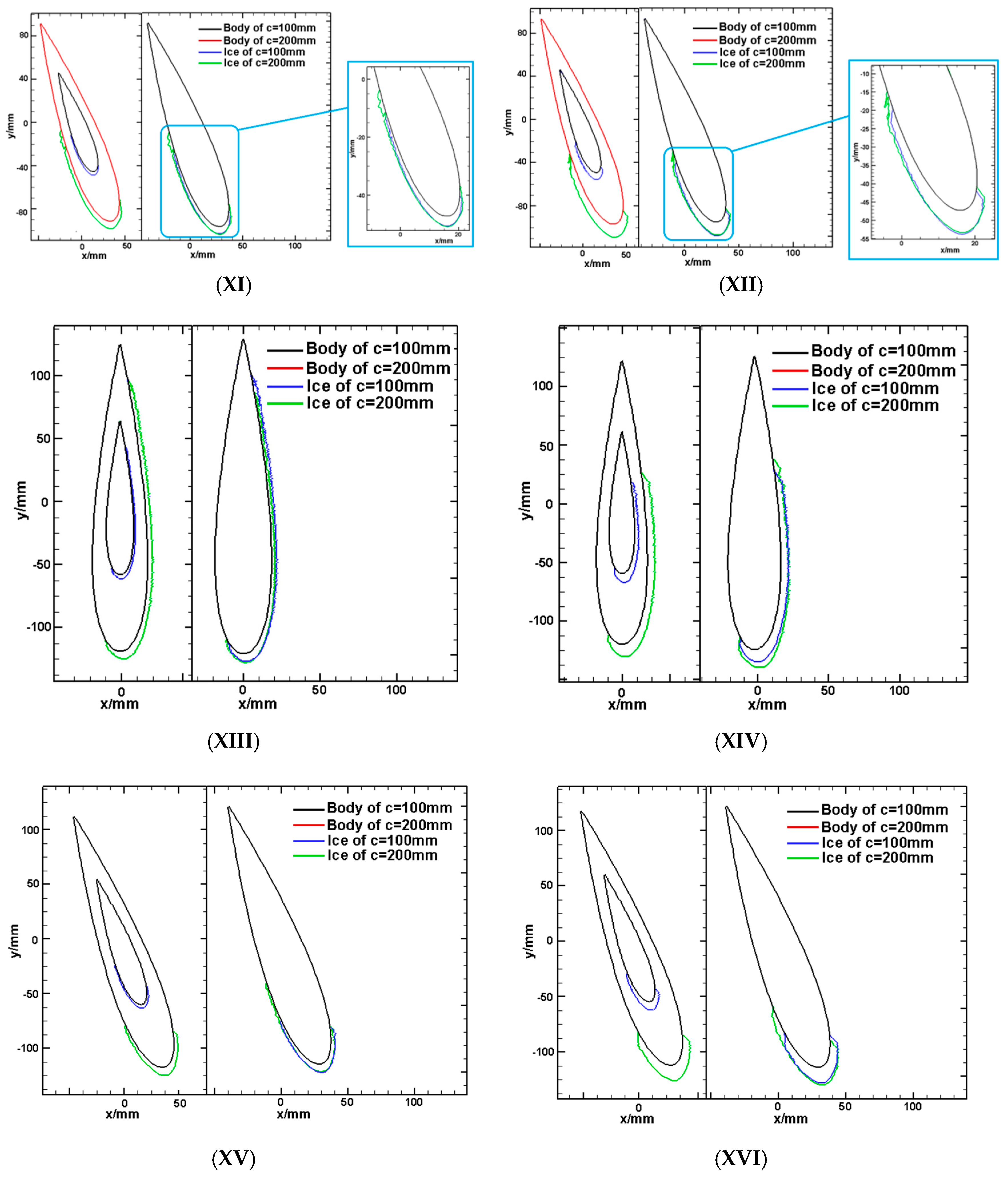
3.1. Icing Shape

Figure 7 shows the icing shapes under No. 1, No. 2, No. 11 and No. 12 conditions for the subscale model and full-scale model. Under the conditions of No. 1 and No. 2, the ice accretes on the whole windward surface of blades, in both the subscale model and full-scale model. The icing shape of the subscale model is similar to that of the full-scale model. Under the conditions of No. 11 and No. 12, the ice accretes on a small part of windward surface and a large part of leeward surface of blades, for both models, and their icing shapes are similar. To evaluate the icing shapes of different scale models, the icing shapes were unified into the same coordinate system as shown in Figure 8. The ice on the airfoil cord of 200 mm seems to reach further downstream locations than for the scaled version under most conditions. This is because the medium volume droplet (MVD) is the main parameter that influences the icing area on blade surfaces, perhaps due to the relative MVD (MVD/c) leading to the ice on the airfoil cord of 200 mm, which is further downstream than for the scaled version. The thickness of ice increases with icing time and the ice shape does not change. The icing area gradually concentrates on the leading edge of the blade with the increase of installed angle and rotational speed. The icing shape of the full-scale model was expanded to the subscale model. The results show similar icing shapes between the subscale blade and full-scale blade based on the new rime ice scaling method. The icing shapes of the subscale model coincide with those of the full-scale model. The results indicate that the scaling method established by this study is accurate and reliable.

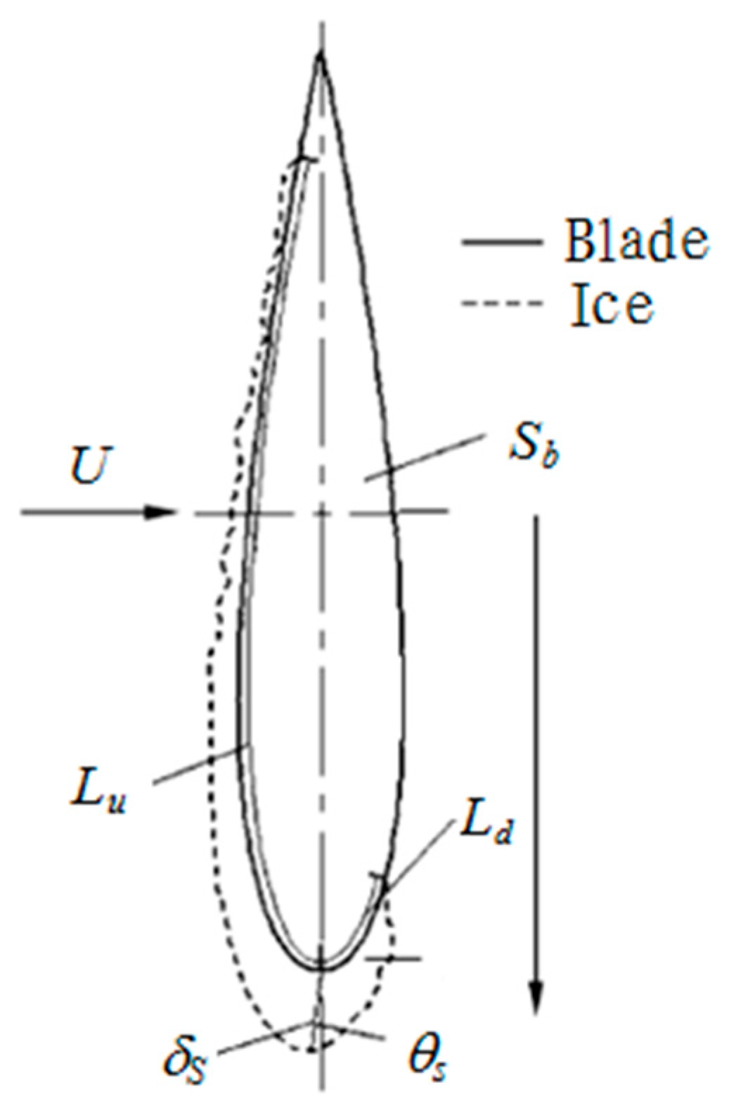
3.2. Similar Icing Shape Evaluation Method

For quantitatively analyzing the similar degree of icing shapes between the subscale model and full-scale model, an evaluation method was proposed based on previous research [30]. According to previous research, there are five main kinds of characteristics of icing shape: icing area Si, stationary point thickness δs, upper impingement limit LU, downer impingement limit LD and stationary point deflect angle θs. Figure 9 shows these characteristics. For comparing and analyzing irregular icing shapes on different scale blade surfaces, these characteristics are dimensionless in this paper. The dimensionless parameters are as follows:
Dimensionless icing area:
η S = S i S b
Dimensionless stationary point thickness:
η δ S = δ S c
Dimensionless upper impingement limit:
η L U = L U c
Dimensionless downer impingement limit:
η L d = L d c
Dimensionless stationary point deflect angle:
η θ s = θ s 180
Difference rate factor ς was proposed in this study to quantitatively analyze the icing shapes for the subscale model and full-subscale model.
Difference rate factor of dimensionless icing area:
ς S = | ( η S ) f ( η S ) m ( η S ) f |
Difference rate factor of dimensionless icing area:
ς δ S = | ( η δ S ) f ( η δ S ) m ( η δ S ) f |
Difference rate factor of upper impingement limit:
ς L U = | ( η L U ) f ( η L U ) m ( η L U ) f |
Difference rate factor of downer impingement limit:
ς L d = | ( η L d ) f ( η L d ) m ( η L d ) f |
Difference rate factor of stationary point deflect angle:
ς θ S = | ( η θ S ) f ( η θ S ) m ( η θ S ) f |
The similar degree was defined as follows:
S i m = [ 1 ( r δ S ς δ s + r S ς S + r L U ς L U + r L d ς L d + r θ S ς θ S ) ] = [ 1 ( 0.3 ς δ s + 0.3 ς S + 0.15 ς L U + 0.15 ς L d + 0.1 ς θ S ) ]
where ri is the weighting factor. It is defined based on the importance of characteristics of the icing shape.
Table 2 shows the similar degree of icing shapes between these two scale blade models. The results show that the similar degree is between 75.22% and 93.01%. The results show the effectiveness of the new rime ice scaling method.

4. Conclusions

The main conclusions obtained in this research are as follows:
(1)
The rime ice scaling method has been established. The scaling parameter requirements including flow field, droplet trajectory, droplet impinging mass, thermodynamic, dynamic pressure, liquid water dynamic are defined. The rotating parameter based on the centrifugal force is added into the new rime ice scaling method.
(2)
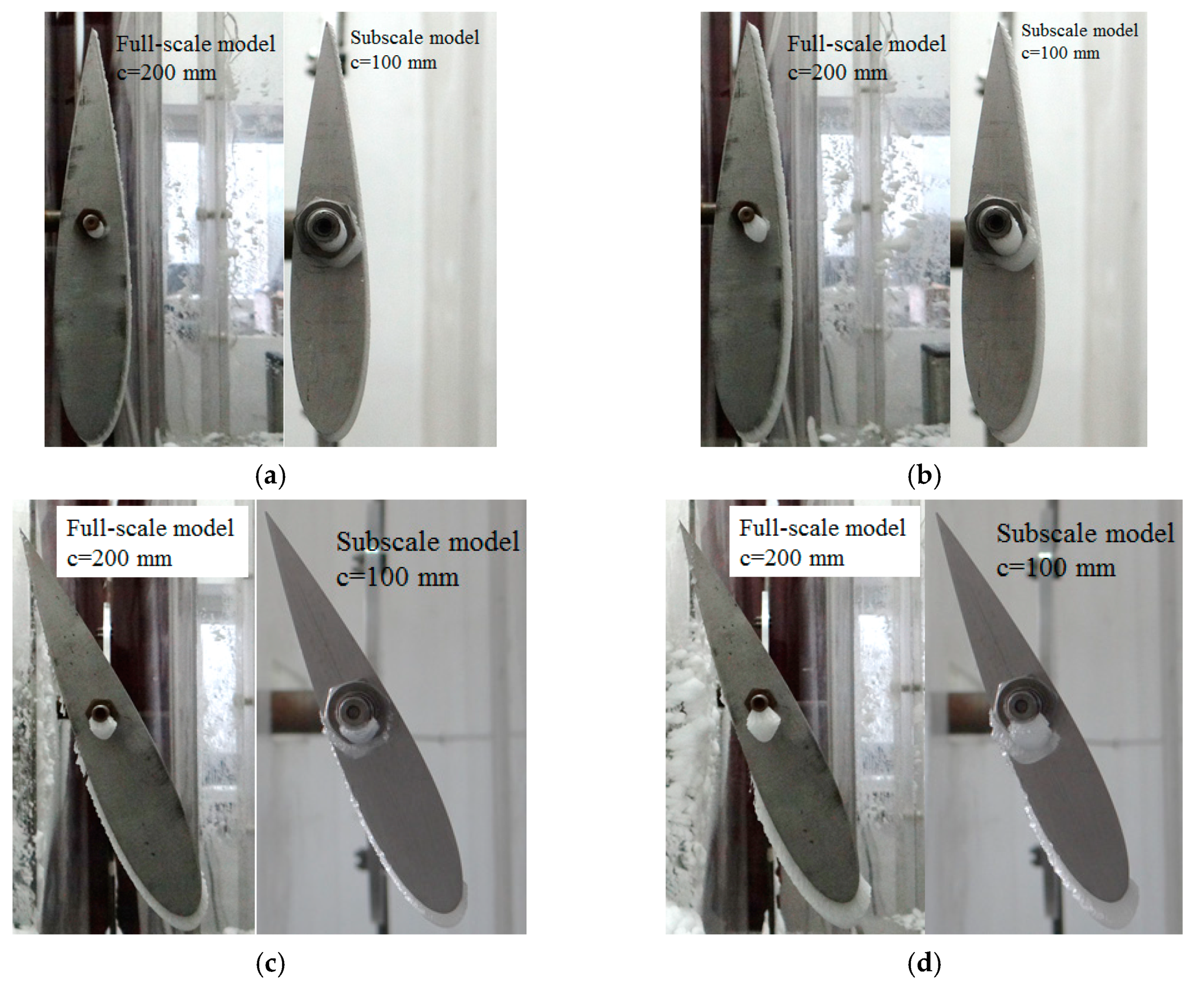
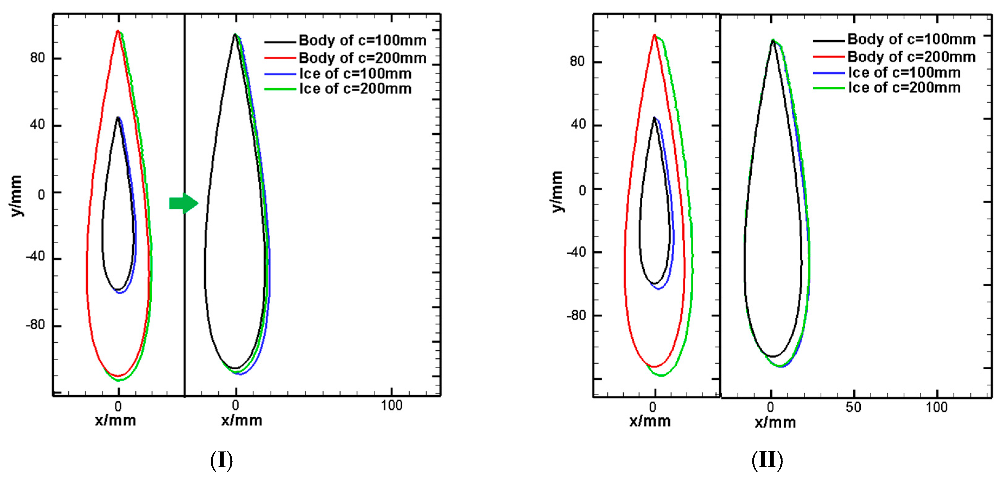
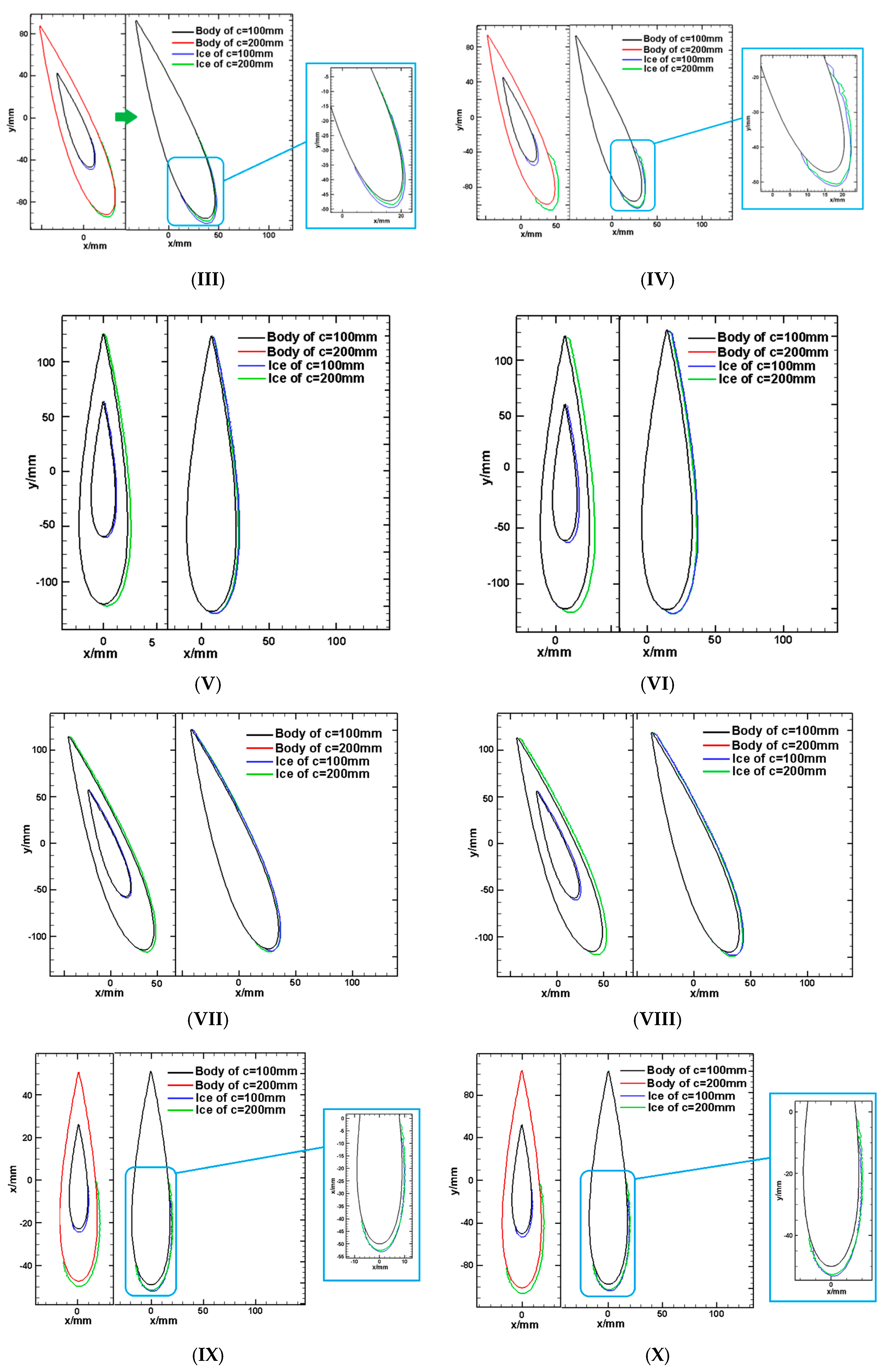
The icing wind tunnel verification tests were carried out. The results show that the icing shapes of subscale blade are similar to those of the full-scale blade.
(3)
An evaluation method for analyzing the similar degree of icing shapes on different scale blades has been proposed. The similar parameter similar degree (Sim) is proposed. The results show that the similar degree of icing shapes of subscale model and full-scale model is between 75.22% and 93.01%. The value indicates that the new rime ice scaling method is an effective method

Author Contributions

Conceptualization, Y.L. and C.S.; Methodology, Y.L. and C.S.; Validation, Y.L., C.S. and Y.J.; Formal Analysis, Y.L. and C.S.; Investigation, C.S.; Resources, Y.L.; Data Curation, F.F.; Writing-Original Draft Preparation, Y.L. and C.S.; Writing-Review & Editing, Y.L. and C.S.; Project Administration, Y.L. and F.F.; Funding Acquisition, Y.L.

Funding

This research was sponsored by the projects supported by the National Natural Science Foundation of China (NSFC, No. 51576037). The authors are grateful for the support.

Conflicts of Interest

The authors declare no conflict of interest.

Nomenclature

cChord length (m)ηDimensionless method
bBladeδSStationary point thickness (mm)
DRotor diameter (m)LdDowner impingement limit
EEnergy (J)LuUpper impingement limit
fFull-scale modelvPeripheral speed (m/s)
LIcing limit (mm)αsDeflection angle of icing
LWCLiquid water content (g/m3)θRotation angle of airfoil (°)
MVDMedium volume droplet diameter (μm)covcover
mSubscale modelScovIcing area (mm2)
QQuantity of heat (J)tIcing time (s)
UVelocity of wind flows (m/s)TTemperature (°C)
SimSimilar degree (%)ςDifference rate factor
riWeighting factorHAWTHorizontal axis wind turbine
Acaccumulation parametermwWater mass (g)
KInertia parameterK0Modified inertia parameter
ReFree Reynolds number of dropletsRerelRelative Reynolds number of droplets
βLocal impingement efficiencyσcRotating parameters scaling requirement
SiIcing area (mm2)SbBlade area (mm2)
θsStationary point deflect angle (°)αInstalled angle (°)

References

  1. Li, Y.; Zhao, S.; Tagawa, K.; Feng, F. Starting performance effect of a truncated-cone-shaped wind gathering device on small-scale straight-bladed vertical axis wind turbine. Energy Convers. Manag. 2018, 167, 70–80. [Google Scholar] [CrossRef]
  2. Zhao, Z.Z.; Qian, S.Y.; Zheng, Y.; Wang, R.X.; Zeng, G.S. Enhancement approaches of aerodynamics performance of lift type vertical axis wind turbine considering small angle of attack. J. Drain. Irrig. Mach. Eng. (JDIME) 2018, 36, 146–153. (In Chinese) [Google Scholar]
  3. Li, Y.; Zheng, Y.F.; Zhao, S.Y.; Feng, F.; Li, J.Y.; Wang, N.X.; Bai, R.B. A review on aerodynamic characteristics of straight-bladed vertical axis wind turbine. Acta Aerodyn. Sin. 2017, 35, 368–382. (In Chinese) [Google Scholar]
  4. Zhang, Y.; Tang, N.; Niu, Y.; Du, X. Wind energy rejection in China: Current status, reasons and perspectives. Renew. Sustain. Energy Rev. 2016, 66, 322–344. [Google Scholar] [CrossRef]
  5. Li, Y.; Tagawa, K.; Feng, F.; Li, Q.; He, Q. A wind tunnel experimental study of icing on wind turbine blade airfoil. Energy Convers. Manag. 2014, 85, 591–595. [Google Scholar] [CrossRef]
  6. Xian, Y.; Kaichun, W.; Honglin, M.; Guolin, Z. 3-D numerical simulation of droplet collection efficiency in large-scale wind turbine icing. Acta Aerodyn. Sin. 2013, 31, 745–751. (In Chinese) [Google Scholar]
  7. Shu, L.; Li, H.; Hu, Q.; Jiang, X.; Qiu, G.; He, G.; Liu, Y. 3D numerical simulation of aerodynamic performance of iced contaminated wind turbine rotors. Cold Reg. Sci. Technol. 2018, 148, 50–62. [Google Scholar] [CrossRef]
  8. Li, Y.; Wang, S.; Sun, C.; Yi, X.; Guo, W.; Zhou, Z.; Feng, F. Icing distribution of rotating blade of horizontal axis wind turbine based on Quasi-3D numerical simulation. Therm. Sci. 2018, 22, 1191–1201. [Google Scholar] [CrossRef]
  9. Wang, S. Numerical Simulation and Icing Wind Tunnel Test Study on Icing Distribution on Rotating Blade of Horizontal Axis Wind Turbine. Ph.D. Thesis, Northeast Agricultural University, Harbin, China, 2017. [Google Scholar]
  10. Hu, L.; Zhu, X.; Chen, J.; Shen, X.; Du, Z. Numerical simulation of rime ice on NREL Phase VI blade. J. Wind Eng. Ind. Aerodyn. 2018, 178, 57–68. [Google Scholar] [CrossRef]
  11. Zhang, Y.; Liu, K.; Xian, H.; Du, X. A review of methods for vortex identification in hydroturbines. Renew. Sustain. Energy Rev. 2018, 81 Pt 1, 1269–1285. [Google Scholar] [CrossRef]
  12. Li, Y.; Wang, S.; Liu, Q.; Feng, F.; Tagawa, K. Characteristics of ice accretions on blade of the straight-bladed vertical axis wind turbine rotating at low tip speed ratio. Cold Reg. Sci. Technol. 2018, 145, 1229–1236. [Google Scholar] [CrossRef]
  13. Zeng, J.; Song, B. Research on experiment and numerical simulation of ultrasonic de-icing for wind turbine blades. Renew. Energy 2017, 113, 706–712. [Google Scholar] [CrossRef]
  14. Gao, L.; Liu, Y.; Zhou, W.; Hu, H. An experimental study on the aerodynamic performance degradation of a wind turbine blade model induced by ice accretion process. Renew. Energy 2019, 133, 663–675. [Google Scholar] [CrossRef]
  15. Jolin, N.; Bolduc, D.; Swytink-Binnema, N.; Rosso, G.; Godreau, C. Wind turbine blade ice accretion: A correlation with nacelle ice accretion. Cold Reg. Sci. Technol. 2019, 157, 235–241. [Google Scholar] [CrossRef]
  16. Taylor, G.L. Notes on Possible Equipment and Technique for Experiments on Icing on Aircraft; R&M, No. 2024; HM Stationery Office: Richmond, UK, January 1940. [Google Scholar]
  17. Langmuir, I.; Blodgett, K.B. A Mathematical Investigation of Water Droplet Trajectories; Army Air Forces Technical Report No. 5418 (Contract No. W-33-038-ac-9151); Army Air Forces Headquarters, Air Technical Service Command: San Antonio, TX, USA, February 1946. [Google Scholar]
  18. Wang, Z.X. Numerical Simulation of Droplet Impact Characteristic about Aircraft Icing and Study on Icing Scaling Law. Ph.D. Thesis, China Aerodynamics Research and Development Center Graduate School, Mianyang, China, 2008. [Google Scholar]
  19. Hauger, H.H.; Englar, K.G. Analysis of Model Testing in an Icing Wind Tunnel; Report No.SM14933; Douglas Aircraft Company, Inc.: Santa Monica, CA, USA, 1954. [Google Scholar]
  20. Jackson, E.T. Development Study: The Use of Scale Models in an Icing Tunnel to Determine the Ice Catch on a Prototype Aircraft with Particular Reference to Concorde; SST/B75T/TMMcK/242; British Aircraft Corp. (Operating) Ltd., Filton Division: London, UK, July 1967. [Google Scholar]
  21. Ormsbee, A.I.; Vragg, M.B. Trajectory Scaling Laws for a Particle Injected into the Wake of an Aircraft; Report ARL-1; University of Illinois, Aviation Research Laboratory: Chicago, IL, USA, June 1978. [Google Scholar]
  22. Armand, C. Techniques and Facilities Used at the OneraModane Centre for Icing Tests; AGARD-AF-127; North Atlantic Traty Organization Advisory Group for Aerospace Research and Development: Neuilly sur Seine, France, November 1978. [Google Scholar]
  23. Ruff, G.A. Analysis and Verification of the Icing Scaling Equations; AEDC-TR-85-30, Vol 1 (Rev); NASA: Washington, DC, USA, March 1989.
  24. Bilanin, A.J. Proposed Modifications to the Ice Accretion/Icing Scaling Theory, AIAA Paper AIAA-88-0203; AIAA: Reston, VA, USA, January 1988.
  25. Bilanin, A.J.; Anderson, D.N. Ice Accretion with Varying Surface Tension, AIAA 95-0538 and NASA TM10682; NASA: Washington, DC, USA, January 1995.
  26. Anderson, D.M. Rime-, Mixed- and Glaze-Ice Evaluations of Three Scaling Laws, AIAA 94-0718; AIAA: Reston, VA, USA, January 1994.
  27. Xian, Y. Numerical Computation of Aircraft Icing and Study on Icing Test Scaling Law. Ph.D. Thesis, China Aerodynamics Research and Development Center Graduate School, Mianyang, China, 2007. [Google Scholar]
  28. Han, Y.; Palacios, J.; Schmitz, S. Scaled ice accretion experiments on rotating wind turbine blade. J. Wind Eng. Ind. Aerodyn. 2012, 109, 55–67. [Google Scholar] [CrossRef]
  29. Li, Y.; Sun, C.; Guo, W.F.; Wang, S.L.; Feng, F.; Jiang, Y. Design of Icing Wind Tunnel Experiment System for Rotating Blades by Using Natural Low Temperature. J. Exp. Fluid Mech. 2018, 32, 40–47. (In Chinese) [Google Scholar]
  30. Li, Y.; Sun, C.; Jiang, Y.; Yi, X.; Xu, Z.; Guo, W. Temperature effect on icing distribution near blade tip of large-scale horizontal-axis wind turbine by numerical simulation. Adv. Mech. Eng. 2018, 10, 1–13. [Google Scholar] [CrossRef]
Figure 1. Flow field around subscale model and full-scale model: (a) Subscale model: c = 100 mm; (b) Full-scale model: c = 200 mm.
Energies 12 00627 g001
Figure 2. Schematic diagram of icing wind tunnel experiment system (IWTES).
Energies 12 00627 g002
Figure 3. 3D diagram of rotation system.
Energies 12 00627 g003
Figure 4. Diagram of actual test section.
Energies 12 00627 g004
Figure 5. Blade model.
Energies 12 00627 g005
Figure 6. Schematic diagram of installed angle (α).
Energies 12 00627 g006
Figure 7. Icing shapes for the subscale model and full-scale model under different conditions: (a) No.1 condition; (b) No.2 condition; (c) No.11 condition; (d) No.12 condition.
Energies 12 00627 g007
Figure 8. Normalization of icing shape comparison under different conditions: (I)~(XVI) express No.1 condition ~ No.16 condition.
Energies 12 00627 g008aEnergies 12 00627 g008bEnergies 12 00627 g008c
Figure 9. Typical characteristics of icing shape.
Energies 12 00627 g009
Table 1. Test plane.
ConditionV/m×s−1T/°CMVD/μmLWC/g×m−3P/Pan/rpmα/°t/s
Subscale ModelFull-Scale Model
16−15500.58101,325200078156
26−15500.58101,3252000156312
36−15500.58101,3252002078156
46−15500.58101,32520020156312
510−15500.58101,325200078156
610−15500.58101,3252000156312
710−15500.58101,3252002078156
810−15500.58101,32560020156312
96−15500.58101,325600078156
106−15500.58101,3256000156312
116−15500.58101,3256002078156
126−15500.58101,32560020156312
1310−15500.58101,325600078156
1410−15500.58101,3256000156312
1510−15500.58101,3256002078156
1610−15500.58101,32560020156312
Table 2. Similar degree between subscale model and full-scale model.
Condition12345678
Sim80.78%89.18%86.08%90.34%75.22%86.10%93.01%85.93%
Condition910111213141516
Sim78.45%79.30%88.83%81.49%81.30%90.36%77.31%81.23%

