Article

Hybrid Multilevel Converters: Topologies, Evolutions and Verifications

1
School of Electrical Engineering, Southeast University, Nanjing 210096, China
2
School of Electrical Engineering and Electronic Information, Xihua University, Chengdu 210024, China
*
Author to whom correspondence should be addressed.
Energies 2019, 12(4), 615; https://doi.org/10.3390/en12040615
Submission received: 7 January 2019 / Revised: 11 February 2019 / Accepted: 12 February 2019 / Published: 15 February 2019

Abstract

:
Multilevel converters have good potential in high power and high voltage applications due to their advantages of reduced voltage or current stress on power devices. In recent years, hybrid multilevel converter (HMC) have attracted increasing attention since less equipment is required. In this paper, the topologies and evolutions of HMCs are presented, where five topology derivation ways are given by using basic cells in series-parallel/parallel-series. Some general topologies or structures that are used to generate higher levels are also deducted. Then many existing HMCs can be derived, and new topologies of the HMC might be inspired. The capabilities of neutral point and FC voltage balancing control are investigated. The performance of the selected FC-based HMCs is analyzed. Finally, the verifications of operation principle and control strategies for the derived HMCs are carried out.

1. Introduction

Multilevel converters have superior characteristics over two-level converters such as lower dv/dt, lower switching losses and better output quality [1,2,3,4]. With the capability of handling high voltage and high power, the multilevel converters (MLCs) are widely used in medium- and high-voltage (>3 kV) power conversion systems [1,2]. MLCs are also suitable in low-voltage (<380 V) power applications, due to the reduced output filter volume or enhanced fault-tolerant capability they may achieve [3,4].
Nowadays, the most common topologies of voltage source MLCs are the diode neutral- point-clamped (NPC) converter [5,6], flying capacitor converter (FCC) [7], cascaded H-bridge (CHB) converter [8,9] and modular multilevel converter (MMC) [10,11]. Three-level NPC converters have been widely used in high-power motor drives and renewable energy conversions. However, as the number of levels increases, the clamping diodes and unbalanced loss distributions will increase rapidly. Due to its merits of the absence of diodes and balanced loss distributions, the FCC is a good alternative for high-level applications. Nevertheless, a large number of flying capacitors (FCs) may reduce system reliability and increase the initial price. Hybrid multilevel converters (HMCs) are new emerging converters which have attracted more and more attention in some applications with high power or high reliability requirements, such as renewable power generation systems and electric aircraft [12,13,14,15,16,17,18,19,20,21,22]. In recent years, some HMCs including active NPC (ANPC) converters [13,14,15,16,17], three-level T-type converter (also known as neutral point piloted converter, NPPC) [18], nest NPC (NNPC) converter [19,20,21], and nest T-type NPC converter [22] have found industrial applications. Developing new multilevel topologies is still of great significance since most topologies may be not suitable for new emerging applications and are difficult to implement in commercialized uses. For example, the three-level T-type converter was invented several decades ago [18], but it has only been studied and applied in recent years for low-voltage applications (e.g., photovoltaic grid-connected system) due to its low conduction losses and superior output quality [4,23,24]. There are several papers in the literature [1,2,3,4,5,6,9], focusing on the topology review of the multilevel converters, and their modulation and control strategies were reviewed in [25,26,27]. However, topology reviews and control strategy of HMCs have rarely been presented in the scientific literature.
The main contributions of this paper are to find derivation ways of HMC topology, especially for the FC-based HMCs. Five evolutions of the HMC are presented by using basic cells in series-parallel/parallel-series and adding/removing power devices, with which many existing and new HMC topologies can be derived. The capabilities of the neutral point (NP) voltage and FC voltage balancing control are investigated and taken into consideration in the topology derivation process. Finally, the fundamental operating principle of three derived HMCs is validated experimentally.

2. Hybrid Stacked Multicell Converters

A large number of multilevel converter topologies have been developed in recent decades to meet the requirement of different applications. Figure 1 shows the classification of multilevel converters, where five existing and emerging hybrid multilevel converters, including hybrid clamped, hybrid cascaded, hybrid FC-based ANPC, hybrid FC-based multicell, and hybrid sub-module multilevel converters are highlighted and discussed in this paper.

2.1. Basic Switching Cells

Figure 2 shows two-level and multi-level basic switching cells, named two-level (2L) cell, three-level H-bridge (3L HB) cell, three-level FC (3L FC) cell, three-level NPC (3L NPC) cell, three-level active NPC (3L ANPC) cell and three-level T-type (3L T-type) cell, respectively. Any HMCs can be derived by stacking the basic cells in adding or removing some devices. The basic cells included in an HMC topology may be one or more cell types, but the cell type is usually limited to two to simplify the topology and reduce the control complexity.

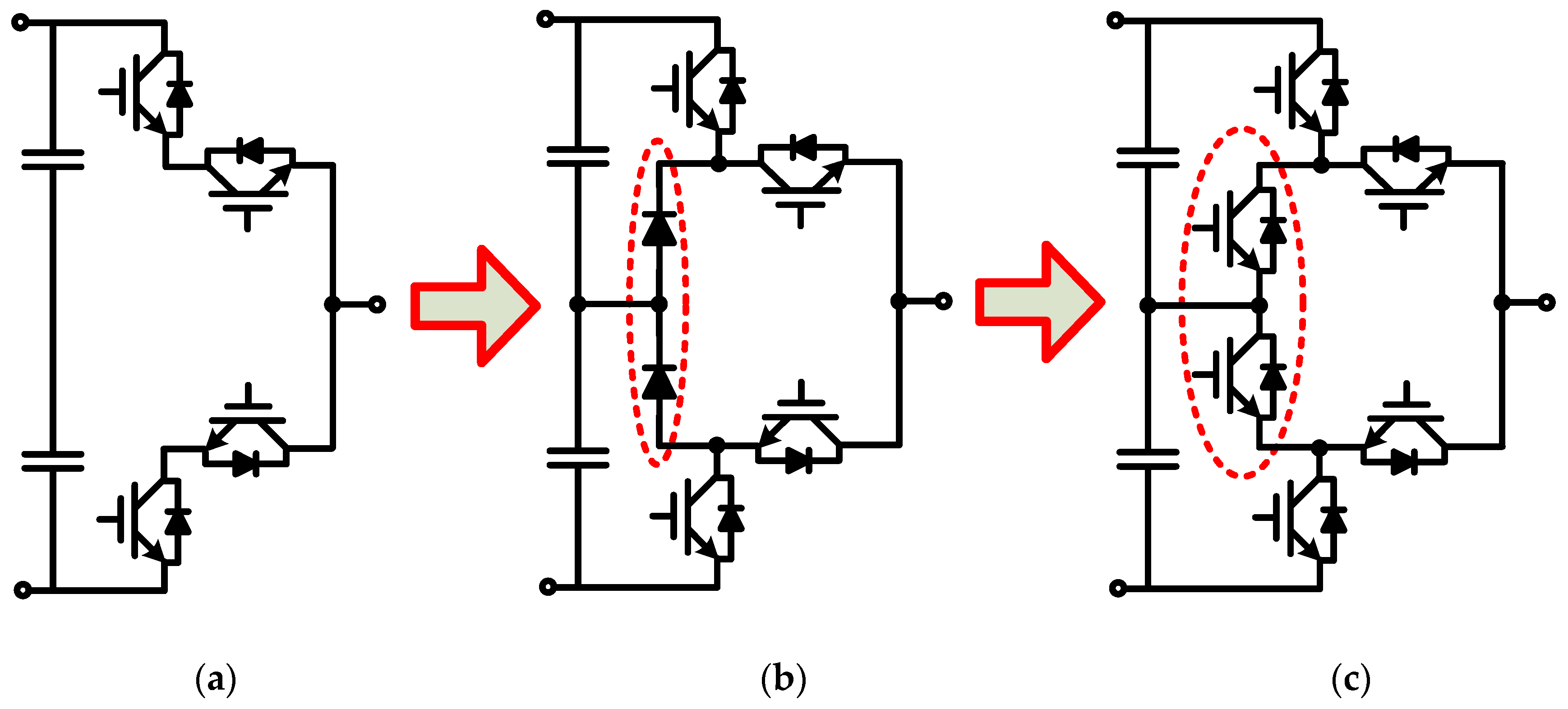
2.2. Hybrid Clamped Multilevel Converters

The ANPC converter is a newly introduced HMC, which combines the advantages of NPC and FCC [13]. In this paper 3L ANPC is considered as basic cell, and from which other HMC such as 5L ANPC can be derived. To demonstrate the derivation principle, the derivation of basic 3L ANPC is also presented, as shown in Figure 3. The basic 3L NPC cell shown in Figure 3b can be seen as a combination of series 2L cell and two clamped diodes. The 3L ANPC is obtained by replacing the clamped diodes of 3L NPC with active switches, as shown in Figure 3c [13,14].
Applying the same derivation principle, a 3L T-type cell with series switches can be seen as a basic cell which is used to derive stacked NPC converters. Figure 4 shows the derivation process of 3L active stacked NPC converter. The 3L stacked NPC converter is derived by adding two clamped diodes into a 3L stacked converter, and then 3L active stacked NPC is obtained by replacing the clamped diodes with active switches as shown in Figure 4b,c [28,29,30].
The stacked multicell (SM) (also named nested neutral point piloted, NNPP) converter is a kind of HMC [28], and it owns some merits, such as modularity and inherent natural voltage balancing of FCs. Figure 5 shows the derivation process of 4L NNPC converter [22], and 5L SM converter [28]. The 4L NNPC converter shown in Figure 5b can be obtained with adding into a 3L FC one bidirectional active switch between the neutral point of the FCs and ac output terminal. The 5L SM converter can be obtained by adding a bidirectional active switch into the 4L NNPC between the neutral points of the FCs and dc-link capacitors, as shown in Figure 5c.
Figure 6 shows the derivation process of 5L SM converter and 4L π-type converter [31]. Figure 6 shows the 5L SM converter is formed by stacking two 3L T-type cells horizontally, and 4L π-type converter can be seen as a combination of two T-type cells vertically. More T-type cells should be stacked horizontally and vertically to extend the voltage levels, and then the corresponding general topologies are shown in Figure 6d,e.
Figure 7 shows another derivation way of 4L NNPC converter [19]. The 4L NNPC is derived by nest stacking a 2L cell and a 3L NPC as shown in Figure 7. To illustrate the derivation principle, the output of the 2L cell is firstly separated into two terminals, and then connected with the dc-side terminals of 3L NPC. As 3L NPC is replaced with 3L ANPC and 3L T-type converter, 4L nest ANPC and 4L nest T-type NPC converter [22] are derived, respectively. Figure 8 shows three hybrid clamped topologies of 4L nest NPC converters.

2.3. Hybrid Cascaded Multilevel Converters

Some HMCs are derived by cascading one or two types of basic cells in parallel or series. Figure 9 shows a 5L double flying capacitor ANPC (DFC-ANPC) converter [32] and a 9L symmetric hybrid converter [33] obtained by combing two 3L FC cells and one 2L/3L HB cell, respectively. The switches of 3L FC cells operate in high frequency (HF) while switches of the 2L/3L-HB cell operate in low frequency (LF). Due to the topology characteristics, redundant switching states are generated which can be selected flexibly to balance the FC voltage. 3L FC cells can be higher level cells, and 2L/3L-HB cell can also be higher-level cells (e.g., 3L NPC, 3L ANPC, and 3L T-type) to increase the voltage level [34]. Figure 10 shows general topologies of hybrid cascaded multilevel converters.
A large number of FC will reduce the power density of the specific converters. To increase the voltage level with reduced FC, 3L FC cells in Figure 9 can be replaced with 3L ANPC, and 3L T-type cells, the corresponding topologies are shown in Figure 11a,b, respectively [35,36]. The number of levels will be increased by cascading HB cells. To extend the voltage level, Figure 11c shows the general structure of the hybrid cascaded HB converter. It should be noted that the fundamental multilevel cell can be any topology. For example, if the fundamental cell is 5L ANPC and one HB is cascaded, a 9L hybrid cascaded HB converter can be derived [37]. A 17L converter formed by cascading 3L FCC and HB cells is proposed in [38]. The modularity characteristic provides the hybrid cascaded HB converters with fault-tolerant capability, thereby enhancing the system reliability.
If an m-level fundamental cell id cascaded with N HB cells, the output voltage level can be calculated by:
L = 2 m · ( N 1 ) + 1

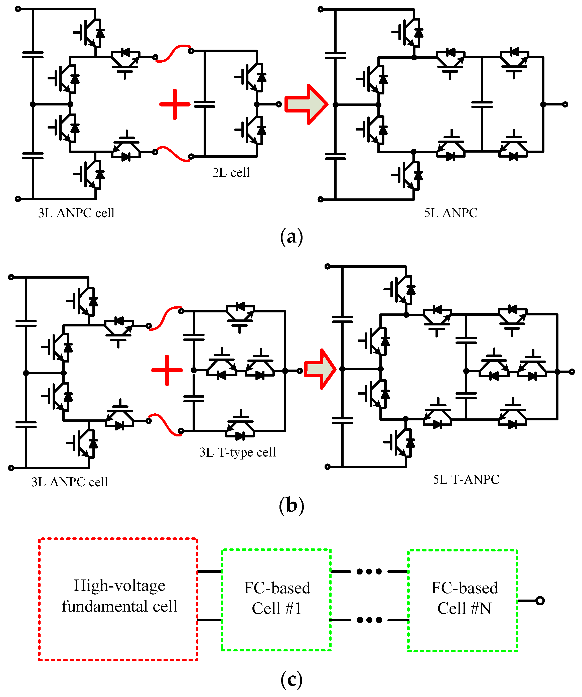
2.4. Hybrid FC-based ANPC Multilevel Converters

The evolution of hybrid FC-based ANPC multilevel converters is shown in Figure 12. 5L ANPC can be seen as a combination of 3L ANPC cell and 2L cell [39], as shown in Figure 12a. Firstly, the ac side output of 3L ANPC is separated into two terminals, and then they are connected with dc-side terminals of the 2L cell. Similarly, if a 3L T-type cell substitutes 2L cell, a new 5L hybrid T-type ANPC (T-ANPC) converter is derived [40], as shown in Figure 12b. Figure 12c shows the general structure with N FC-based cells for generating higher levels, where 3L ANPC is recognized as a fundamental cell, and it can be other topologies. Figure 13 shows three general topologies of hybrid FC-based ANPC converters [39,40,41].

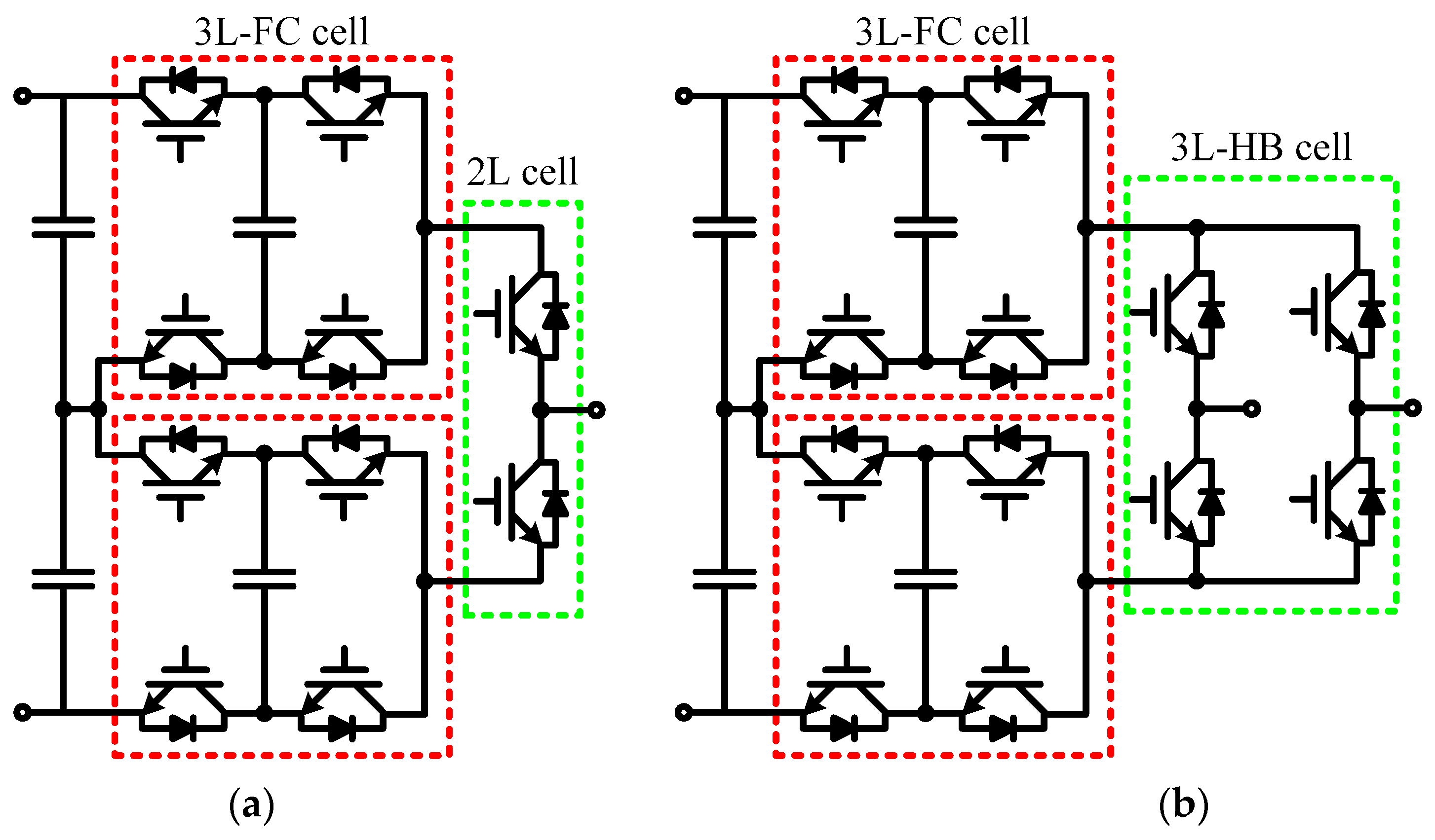
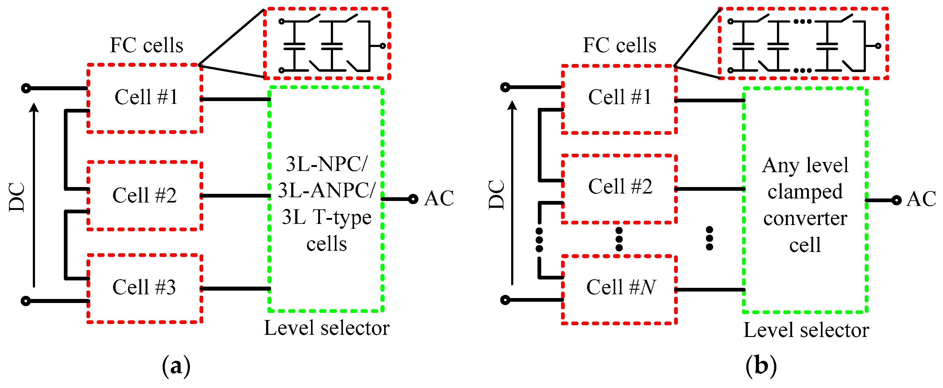
2.5. Hybrid FC-Based Multicell Converters

In order to reduce the required devices (including dc sources, switches, and FCs), several FC-based hybrid multicell converters, which are based on the original FCC and SM converters have been proposed in [42,43,44,45,46,47,48,49,50]. In [42,43], the number of dc sources was reduced to half by adding LF switches to the original SMC. In [44], a mixed stacked multicell converter was proposed to double the RMS value of output voltage, which is obtained by adding four LF switches to the SM converter.
To further reduce the number of LF and HF switches, hybrid FC-based multicell converters have been proposed based on the original FCC and SM converters by introducing only two LF switches, as shown in Figure 14a,b, respectively [45,46]. For obtaining an identical output level, the number of HF switches is reduced to half whereas the RMS value of the output voltage is doubled by comparing with their original topologies. Figure 14c shows the general structure that includes one LF cell and n FC-based HF cells. It should be noted that a higher number of levels can be obtained by stacking more LF and FC-based HF cells. By using this derivation method, a 17L reduced-component hybrid FC-based multicell converter is derived in [47]. Figure 15a shows a hybrid converter named duo-active-neutral-point-clamped multilevel converter, and it is derived by introducing one LF cell to the original ANPC [48,49]. Following the same derivation principle, a new hybrid converter can be obtained from the hybrid T-ANPC converter, as shown in Figure 15b. The general structure is shown in Figure 15c. The derivation ways in this section may reduce the number of HF switches, FCs, and meanwhile double the RMS value of output voltage (i.e., 2Vdc) and improve the quality of output waveforms.

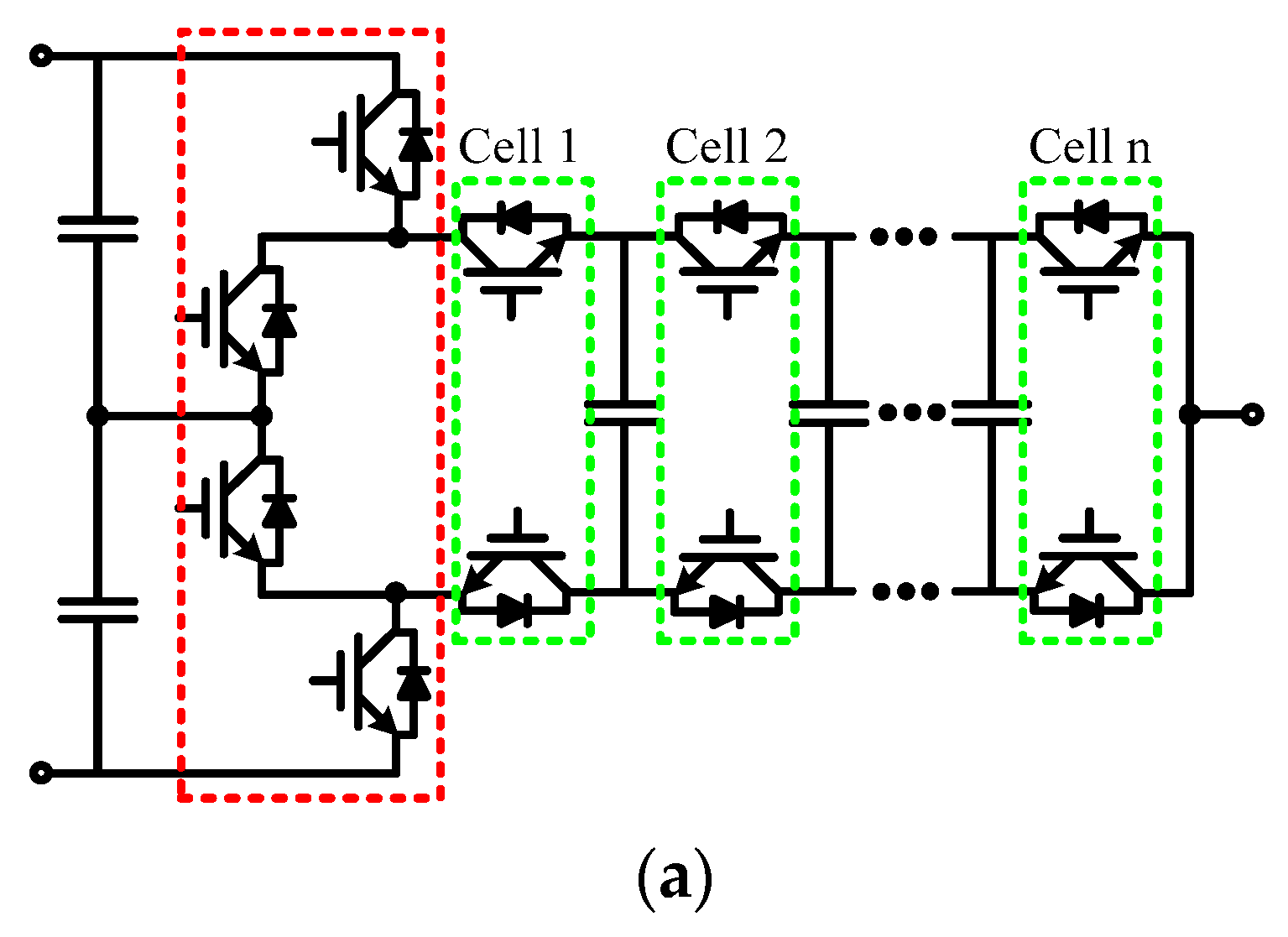
2.6. Hybrid Sub-Module Multilevel Converters

For power converters, modularity means a cascaded connection of sub-module, which is an attractive solution to tolerant high-voltage and obtain high-quality waveforms [51,52]. During past decade, many modular multilevel converter (MMC) topologies have been proposed [53,54,55,56,57,58,59,60,61,62,63,64,65,66,67,68,69], and they are becoming attractive in both academic research and industrial applications.

2.6.1. Basic Cells

The sub-module of the MMC could be established by basic cells and connected in series and parallel to meet the requirement of specific applications, such as high-voltage dc transmission (HVDC), high power motor drive and so on. Figure 16 shows the structures of the basic cell, where 2L half-bridge sub-module (HBSM) and 3L full-bridge sub-module (FBSM) are most common used. The basic cells may adopt multilevel converter cell to increase the output voltage levels, such as 3L neutral-point-clamped sub-module (NPCSM) [5], 3L flying capacitor sub-module (FCSM) [7], 3L active NPC sub-module (ANPCSM) [13], and 3L T-type multilevel sub-module (TMSM) [18].

2.6.2. Hybrid Sub-Modules

By combing the HBSM and FBSM cells, hybrid sub-modules can be derived to achieve desired functions and characteristics, as shown in Figure 17, Figure 18 and Figure 19. A double-half-bridge-series sub-module (DHBSSM) is generated by the connection of two HBSM cells in series, as shown in Figure 17b [53]. Another asymmetrical double HBSM is shown in Figure 17c, which is derived by connecting two HBSM cells in parallel and can generate four-level output. The derived sub-modules by connecting two FBSM cells in series or parallel are shown in Figure 18 [54,55,56]. A hybrid-series-connected sub-module (HSSM) is obtained by combining HBSM and FBSM cells in series [57], as shown in Figure 19. It can output an asymmetric four-level voltage between output terminals.
In order to promote reliability of HVDC transmission system with overhead lines, new hybrid sub-modules with inherent DC fault blocking capability have been proposed in [57,58,59,60,61,62,63,64]. The hybrid sub-modules with asymmetrical DC fault blocking capability includes HSSM, clamp-double sub-module (CDSM) [58], diode-clamp sub-module (DCSM) [59], and switched capacitor sub-module (SCSM) [60]. The hybrid sub-modules with symmetrical DC fault blocking capability includes FBSM, series-connected-double sub-module (SCDSM) [61], cross-connected-double sub-module (CCDSM) [62], clamp-circuit sub-module CCSM) [63], and active clamped T-type sub-module (ACTSM) [64]. Figure 20 gives the topology of some typical hybrid sub-modules.
Obviously, more devices are adopted in the single hybrid sub-module than the HBSM. However, the hybrid sub-module based MMC may be favorable in some specific applications, such as flexible HVDC transmission system with DC fault blocking capability, multiple voltage levels with minimizing devices.
Five topology evolutions and simplified general structures of HMCs have been illustrated above. Many existing and new HMCs can be obtained for various energy conversion systems. The voltage balancing properties of NP and FC are critical issues that should be taken into consideration during topology evolutions. Figure 21 shows the derivation process of the HMC which includes three steps: 1) Evolving new topologies based on basic cells; 2) Analysis of FC voltage balancing capability; 3) Analysis of dc-side NP voltage balancing capability.
It should be noted that the balance of dc-side NP voltage may be realized by three phases or back-to-back configurations, so the balance of FC voltage should be given more priority than that of NP voltage. Typically, the FCs should operate in high frequency mode, and only switching harmonics exist in the FC voltage. For a certain current direction, the redundant switching states can be selected flexibly to balance the FC voltage by charging or discharging the FCs over each switching cycle.
Due to its intrinsic redundancy and modularity, cascaded multilevel inverter (MLI) achieves high-quality outputs and high reliability [9]. The MLI has been recognized as an important alternative in medium-voltage applications, and many symmetrical and asymmetrical MLI topologies have been proposed by researchers. To boost the number of levels with reduced devices, a level doubling network (LDN) was proposed for the cascaded MLIs [65]. The LDN is achieved by adding a capacitor fed half bridge [65,66,69,70] or a full bridge [67,68] to the MLI topologies. The LDN doubles the voltage levels of a multilevel converter, and it is proven not to consume power during a fundamental cycle. The LDN may also be applicable to other single-phase and three-phase multilevel converters to increase the voltage levels, thereby reducing the size and cost of power filters [71,72].

3. Performance Evaluations of Hybrid FC-Based Multilevel Converters

The number of devices and their ratings are crucial for multilevel converters since they govern converter cost, control complexity, and system reliability. In this section, the most common used FC-based multilevel converters such as FCC, ANPC, SM and some emerging FC-based converters are evaluated. Table 1 shows comparison results among 9L hybrid FC-based multilevel converters, where the number of switches, FCs, dc sources, the peak-to-peak value of output voltage and total standing voltage are evaluated. The results show that the FCC and SM converters have less total standing voltages, but they require more HF switches and FCs. The topology shown in Figure 13b [40], which is the combination of ANPC and SM converters, requires more devices and total standing voltage. In [50], the hybrid cascaded multilevel converter does not require FC, but it needs four isolated dc sources and more switches. The topology arising from Figure 11c [34] reduces the total standing voltage with lower voltage devices, whereas it requires more FCs and HF switches. The modified 9L ANPC shown in Figure 9b [33] and in Figure 11c [37] requires an additional two more LF switches, and the total standing voltages are higher than the hybrid stacked multicell (HSM) converter presented in Figure 14b [46].
It can be seen from Table 1 that the HSM requires less device than other 9L FC-based multilevel converters. To further evaluate its characteristics, the comparison of capacitor stored energy against the common used FC-based multilevel converters FCC, ANPC, SM for generating an identical output voltage (9L, 2Vdc, peak-to-peak value) is studied, as shown in Table 2. The result shows that the HSM converter has the lowest stored energy in capacitors. In high-voltage conversion systems, several low voltage rating switches may be connected in serious to block high voltage if a two-level converter is used. Similarly, low current rating switches may be connected in parallel to meet the high power output requirement. However, the parametric inconsistency may exist among the series- and parallel-connected switches, which may influence the converter performance. The multilevel converters can be used in high-voltage high-power applications while avoid direct series- or parallel connection. To obtain low cost and good performance, the switches with proper voltage ratings should be selected. Table 3 shows the comparison of voltage rating for FC-based multilevel converters.
In some specific applications, higher level converters are required to obtain good output quality of waveforms. Therefore, the comparisons of device count are made for the aforementioned general FC-based multilevel converter topologies. Table 4 shows the comparison results of switches and FCs for generating an output voltage with n levels. To make it more comprehensive, Figure 22 shows the curves of the number of switches and FCs versus the increase of voltage level. Theoretically, the power quality of output waveforms will be improved with the increase of the voltage levels, and then the filter size and cost can be optimized. In practical applications, a proper level should be selected for a specific converter to obtain the desire performance.
For high-voltage applications such as HVDC, a relative high voltage level may be selected for MMCs [51,52,53,54,55,56,57,58,59,60,61,62,63,64,73,74,75,76,77] to meet the required current total harmonic distortion (THD), standing voltages and dv/dt. For medium and low-voltage applications, five and fewer level converters for ANPC [13,14,15,16,17], SM [28], HSM [46] and other FC-based multilevel converters might be optimal at current technical conditions. In recent decades, multilevel converters have been proposed and some converters have been commercialized in motor drivers, flexible alternating current transmission system (FACTS), and HVDC. According to the researches in [1,2,3,4,5,6,7,8,9,25,26,27,78], the advantages, disadvantages, modulation techniques, as well as the applications of these commercial converters, are summarized in Table 5.

4. Modulation and Control Strategies

4.1. General Operation and Control Structure

For each multilevel converter, it is required to develop specific modulation and control strategies to generate proper switching signals for gate drivers according to various control targets. The literature [26,27] studied the well-known modulation and control strategies for the HMCs. Figure 23 shows the general operation and control structure of FC-based multilevel converters for achieving different control targets. In Figure 23, the operation and control structure process can be divided into three steps. The first step is achieving the specific control targets by outer and inner control loops, and then the reference signal v* of the output voltage can be obtained. For example, in motor drive applications the control loops are designed to regulate the speed, and in the case of grid-connected compensators, the target will be harmonic current or reactive power.
The second step including voltage balancing control of NP and FC is optional according to different topologies and applications. The third step is PWM modulation (i.e., SPWM and SVM algorithms) which is used to generate the switching signals Si, (i denotes the number of switches) for the converters. It should be noted that step 2 may be included in step 3 when intelligent control such as model predictive control (MPC), sliding mode control is applied. Meanwhile, the modulator will not be required.

4.2. Pulse Width Modulation Algorithms

Each multilevel converter topology requires proper modulation algorithms in order to achieve minimum losses with highest output performance. The modulation approaches of multilevel converters can be classified into multi-carrier based and vector-based methods, and they are two different methods and have been verified to be equivalent [26,78,79]. Carrier-based pulse width modulation (PWM) is widely used in FC-based multilevel converters and can achieve natural voltage balance of the FCs. Two popular PWM methods named level-shifted PWM (LS-PWM) and phase-shifted PWM (PS-PWM) have been widely used for modulating multilevel converters depending on how the carriers are distributed [80]. Due to the asymmetrical structure of the HMCs, the traditional modulator should be modified for obtaining good performance. For example, the ANPC converter can adopt a hybrid PWM method which is a combination of PS-PWM and LS-PWM methods [81]. In the ANPC and hybrid T-ANPC converters, the switches standing high voltage are operated in LF mode, and the switches standing low voltage are operated in HF mode [82]. Other modulation methods may be more suitable for some specific applications, such as nearest level voltage control (NLC) for modular multilevel converter [83], preprogrammed PWM for low frequency (below 1 kHz) high-power applications (in MW range) [84].

4.3. DC-Link NP Voltage Control

Theoretically, the average currents that flow into and out of the NP should be identical over each fundamental cycle (i.e., 50 Hz) to ensure the voltage balance of the NP [4]. Taking 5L ANPC converter as an example, the output voltage and phase current can be shown in Figure 24. Here the phase current is sinusoidal and in phase with the output voltage (unity power factor) with the modulation index m = 0.9. If the voltage level is E while the output is connected to the NP, the current direction is positive which denotes the current flow out of the NP. If the level is -E while the output is connected to the NP, the current is negative and flows into the NP. The currents that flow into and out of the NP are identical in the duration of -E and E as shown in Figure 24. Similarly, for voltage level 0, the total current that flows through the NP is equal to zero. Therefore, the total current that flows through the NP is equal to zero in each fundamental cycle, which denotes that the NP voltage can be naturally balanced over under a unity power factor.
This analysis principle is also applicable to other multilevel converters with one or more NPs under conditions of any power factors. It should be noted that the voltage balance of the NP is also related with the modulation index, the analysis of NP voltage controllable zone with regards to power factor and modulation index can be found in [85,86].
In the carrier-based modulations, the NP voltage balance problem can be solved by using zero-sequence voltage injection methods [87,88]. In [89], the theoretical analysis and control of the NP voltage balance were put forward for 5L ANPC based on the PS-PWM algorithm. In SVM-based methods, the voltage balance of NP is usually achieved by adjusting the redundant space vectors and their time durations [90]. In [91], an active voltage balancing method was proposed for 5L NNPP converter, which is implemented by using dynamic models. Zero-sequence injection in carrier-based methods and redundant space vector selection in SVM-based methods are verified to be equivalent.

4.4. FC Voltage Balancing Control

For most of FC-based multilevel converters, the FC voltages are balanced by selecting redundant switching states in a single phase. The redundant state selections occur in each switching cycle, and the FC Cf is designed as:
C f = I m Δ V f 1 f s
where, Im is the peak value of the phase current ix (x = a, b, c), ΔVf is the allowed voltage ripple of the FC, fs is the switching frequency.
Numerous voltage balancing control methods have been proposed for FC-based multilevel converters [92,93,94,95,96,97,98]. These methods can be classified into two groups: nature voltage and active voltage balancing methods. Nature voltage balancing methods were put forward based on PS-PWM [92,93] and PD-PWM [94,95]. They are easy to be implemented, but the control performances depend on the load power factor and switching frequency. Active voltage balancing methods can be found in [96,97,98]. In [96], an SVM-based voltage balancing method was proposed, and it is only applicable to three-phase systems. In [97,98], the active voltage balancing method was proposed for 5L SM converter based on the PD-PWM and PS-PWM algorithms, respectively.
The capacitor voltage (including FC and NP) balancing control methods are classified into “single phase method” and “three-phase method” [4]. For the FC-based multilevel converters (e.g., FCM, ANPC, and SM), the voltage balance of FC and NP can be achieved by selecting redundant switching states, which is “single-phase method”. For the converters with no redundant states, there is no possibility to use the “single-phase method”, so for some NPC converters such as 3L NPC [5], 3L T-type [18] and 4L π-type converters [31] which have no FC and redundant state, the voltage balance of NP can be realized by minimizing the objective cost function Δε. It is defined as:
min Δ ε = min { x = a , b , c j = 1 n ( v C x j V d c n ) · i C x j }
where n is the number of capacitors, iCj is the capacitor current, Vdc is the total dc-link voltage, VCj and iCj are the capacitor voltage and current, respectively.

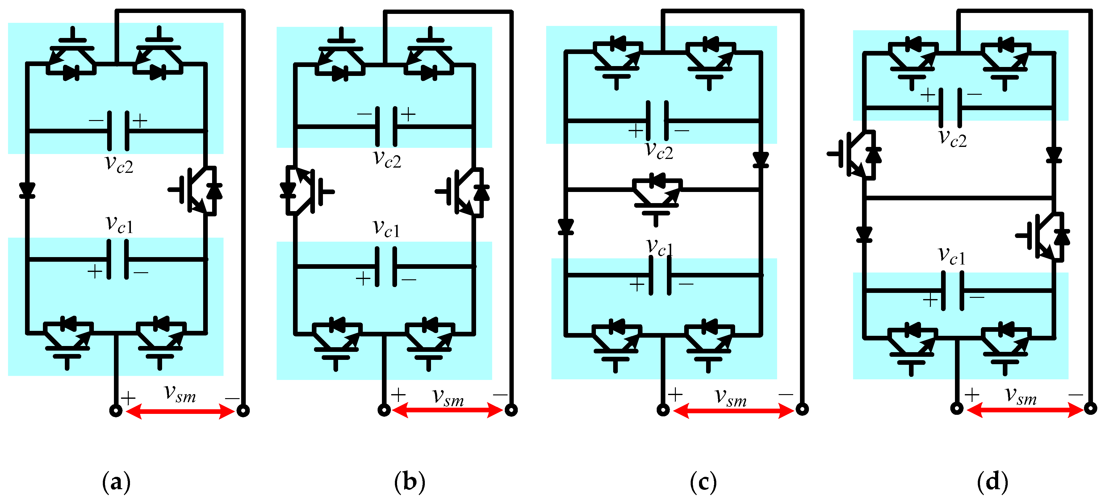
5. Operation of Derived HMCs

The hybrid FC-based ANPC converter and hybrid FC-based multicell converter have the advantages of high redundancy, flexible in FC voltage control, easy to balance NP voltage and high capability in tolerant control. So three typical FC-based HMCs are discussed in the following parts.
Figure 25 shows a three-phase hybrid T-ANPC converter connected with RL-load. Assuming the dc-bus voltage is Vdc, if the reference voltage of the FCs Cf1 and Cf2 is set as Vdc/4 and Vdc/6, 5L and 7L output voltage will be generated, respectively. The operating principle and control strategy for 5L hybrid T-ANPC were discussed in [40]. The switching states, output voltage and corresponding effects on the FCs of 5L and 7L hybrid T-ANPC converter are shown in Table 6 and Table 7, respectively. It is shown in Table 6 that there are redundant switching states which have same output voltage (such as V2 and V3) except for V1 and V12 and the redundant switching states can be appropriately selected to balance the FC voltages. If the FC voltages are both controlled at Vdc/6, vao can be formulated with switching signals. It has
v a o = 1 2 V d c S 1 + 1 6 V d c ( S 3 + S 11 + S 12 ) 1 2 V d c
where S1, S3, S11, and S12 are switching signals of the switches T1, T3, T11, and T12, respectively.
A 9L HSM converter can be arranged similar as s H-bridge converter, as shown in Figure 26. The main circuit consists of LF cell and two T-type HF cells, where switches of the LF cell operate in fundamental frequency, and the switches of the HF cell operate in HF PWM mode. If the dc source voltage is Vdc, the voltage of FCs Cf1 and Cf2 should be maintained at Vdc/4. Table 8 shows the switching states, output voltage and effects on the FCs. The output voltage va can be synthesized to obtain nine levels (±Vdc, ±3Vdc/4, ±Vdc/2, ±Vdc/4, 0) by selecting the proper switching state among eighteen states (V1~V18). These state redundancies can be selected flexibly to charge or discharge FCs for maintaining balanced FC voltages. According to Table 8, the output voltage va can be formularized by:
v a = V d c S 1 + 1 4 V d c ( S 11 + S 12 + S 21 + S 22 )

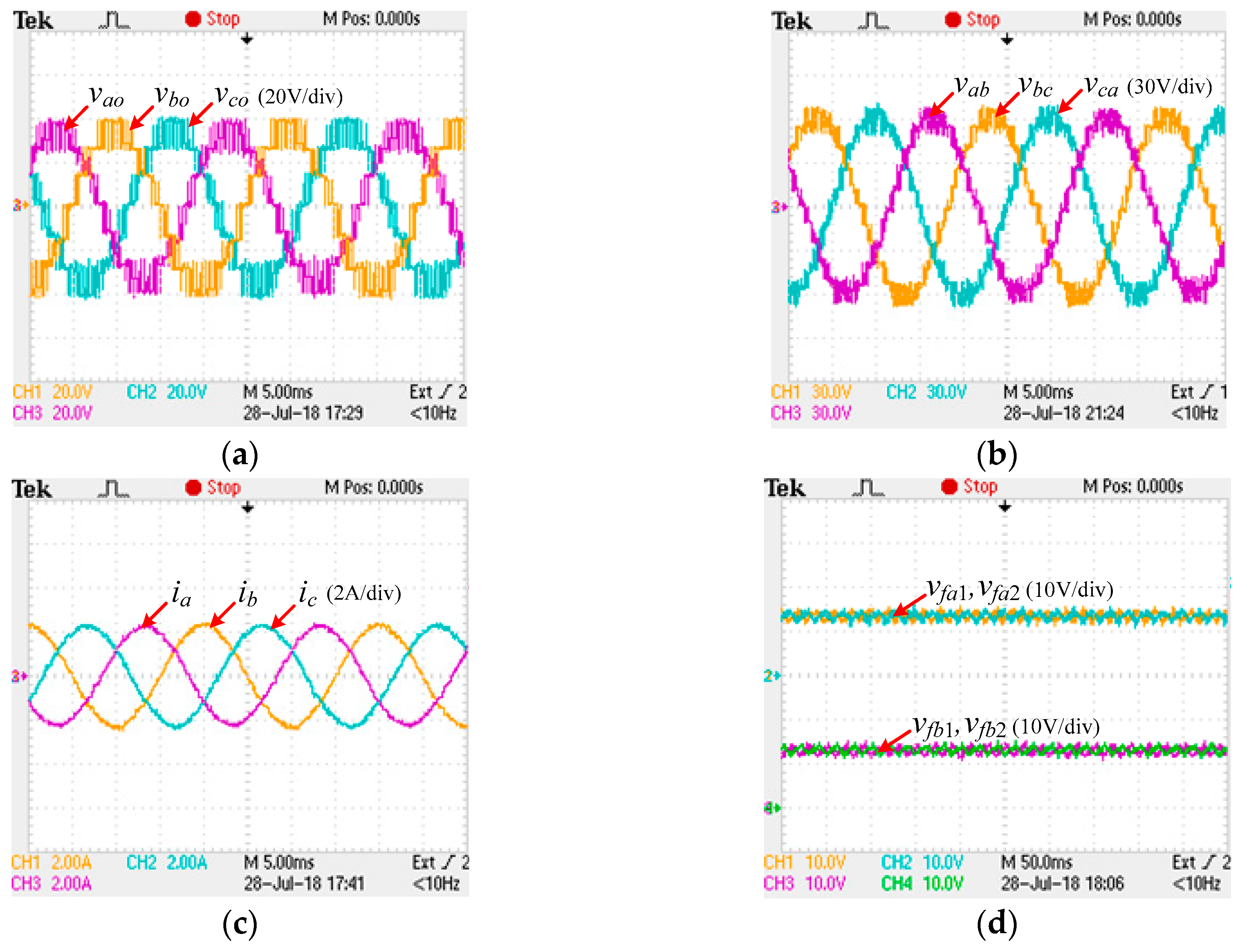
6. Experimental Validations

In this section, the operating principle, modulation and control strategies of three selected FC-based HMCs are validated experimentally. The experimental platform consists of main circuit, voltage and current sensing circuits, controller and PWM driving circuits. The insulated-gated bipolar transistors (IGBTs) IHW15N120E1 and electrolytic capacitors with 820 μF are adopted in the main circuit. A real-time MicroLAB board/module is used to implement the ADC samplings, logical calculations, and control strategies. The dc bus is supplied with a constant dc source, and the ac side terminals are connected to a resistor load through a filtering inductor (L = 4.3 mH, R = 15 Ω).

6.1. Five-Level Hybrid T-ANPC Converter

The hybrid T-ANPC converter is an interesting HMC, and it can operate in different FC voltage ratings Vdc/4 and Vdc/6 to generate 5L and 7L voltage, respectively. This feature enables it to obtain higher levels with reduced total standing voltage of switches and FCs. For 5L and 7L hybrid T-ANPC converters, the voltage balance of the FCs is achieved by selecting the redundant switching states at each switching cycle, and the dc-link NP voltage is balanced by using the zero-sequence voltage injection method.
Figure 27 shows steady-state experiment results of 5L hybrid T-ANPC converter connected with three-phase linear RL-load. Here, the dc source voltage Vdc is 80 V, and a hybrid PS-PWM strategy with carrier frequency fc = 2 kHz, modulation index m = 0.9 is adopted to generate desired voltage levels. At each voltage level, the FC voltages are balanced and maintained at Vdc/4 by selecting appropriate switching states according to the current directions and voltage deviations of the FCs. 5L phase voltage and 9L line-to-line voltage are obtained well, as shown in Figure 27a,b. The load currents are close to a sinusoidal waveform, and FC voltages of A and B phases are balanced well, as shown in Figure 27c,d.

6.2. Seven-Level Hybrid T-ANPC Converter

If the FC voltages vfx1, vfx2 are controlled at Vdc/6, the hybrid T-ANPC converter will generate seven levels, as shown in Table 7. The voltage balance of the FCs can also be achieved by selecting redundant switching states while the NP voltage is balanced by using the zero-sequence voltage injection. The experiment results of 7L hybrid T-ANPC converter are shown in Figure 28, where the phase voltage and line-to-line voltages are 7 levels and 13 levels, respectively. The FC voltages of A and B phases are balanced and maintained at their desired value, with some HF switching harmonics are observed. Figure 29 shows the experiment results of dc-link capacitor voltages for 5L and 7L hybrid T-ANPC converter. It can be seen in Figure 29 that the capacitor voltages of two converters are both balanced well. The above experiment results verify the effectiveness of the control strategies for the hybrid T-ANPC converters.
The power quality of output waveforms is evaluated for the hybrid T-ANPC converter. Figure 30a,b show FFT spectra of the phase current ia for 5L and 7L hybrid T-ANPC converters, respectively. As shown in Figure 30, the hybrid T-ANPC converter with two FC voltage ratings has low total harmonic distortion (THD) as 3.64% and 3.13%, respectively.

6.3. Nine-Level Hybrid Stacked Multicell Converter

To verify the modulation and control strategy of the HSM converter shown in Figure 26, a low-scale experimental platform based on single-phase 9L HSM converter with two T-type cells is constructed where the dc source voltage Vdc is 50 V and the reference voltage of FCs Cf1, and Cf2 is set as Vdc/4. The ac side output terminals X1 and X2 are series connected with a resistor load through a filtering inductor (L = 4.3 mH, R = 15 Ω). A finite control-set MPC approach is developed for this 9L HSM converter to balance FC voltages and maintain desired outputs, and then no PWM modulator and the linear regulator is required. Thus the control complexity is simplified.
Figure 31 shows steady-state experiment results of 9L HSM converter with the MPC strategy. Figure 31a shows the switching signal S1 of T1 is same with fundamental frequency (50 Hz) while S11, S12, and S21 of switches T11, T12, and T21 in HF cells are in high frequency. Figure 31b shows the output voltage vao between terminal X1 and o. The phase voltage vao and load current ia are shown in Figure 31c. Figure 31d shows the voltage deviations Δvf1 and Δvf2 of FCs (Δvf1 = vf1Vdc/4; Δvf2 = vf2Vdc/4), phase current and its reference signal. It can be seen in Figure 31d that the voltage derivations and current tracking error are quite small and only high-frequency components are observed. Therefore, good steady-state performances of the MPC for 9L HSM converter are verified by the experiment results. Figure 32 shows the transient state experiment results of 9L HSM converter with linear RL-load. Figure 32a shows experiment results with the output frequency fout changing from 50 Hz to 100 Hz. It can be seen that the desired phase voltage and load current are obtained well, and no voltage spikes are observed in the FC voltage even during transient process. As can be seen in Figure 32b, the capacitor voltages can be able to maintain balance with a slope increase of Vdc from 0 to 50 V.

7. Conclusions

The topologies and evolutions of HMCs are studied in this paper. Five derivation methods are proposed to form hybrid topologies by using basic cells in series-parallel/parallel -series and adding/canceling devices. Some general topologies that are used to generate higher levels are also deduced. Then most of existing HMCs can be derived, and further new HMC topologies might be inspired that are applicable to specific emerging areas in the future years. The comparisons and evaluations of some typical HMCs are investigated, in terms of required devices, standing voltages of switches, stored energies of FCs and topology characteristics. The modulation techniques and control strategies of the HMCs are reviewed, and the balance capability of the NP voltage and FC voltage are investigated. Finally, the operation principle of hybrid T-ANPC converters and 9L HSMC are demonstrated and experimentally validated. Experimental results verify the effectiveness of the control strategies.

Author Contributions

J.Z. conceived and designed the study; S.X. preformed experiments and edited the draft with guidance from J.Z.; Z.D. checked the language of manuscript. J.Z. and X.H. made a significant contribution to the revisions of manuscript.

Funding

This work was supported in part by the National Science Foundation of China under Grants 51577025, and the Zhejiang Key R&D Project under Grant 2017C01043.

Acknowledgments

We thank all the journal editors and the reviewers for their valuable feedback and constructive comments that have contributed to improving this manuscript.

Conflicts of Interest

The authors declare no conflict of interest.

References

  1. Rodriguez, J.; Lai, J.S.; Peng, F.Z. Multilevel inverters: A survey of topologies, controls, and applications. IEEE Trans. Ind. Electron. 2002, 49, 724–738. [Google Scholar] [CrossRef]
  2. Kouro, S.; Malinowski, M.; Gopakumar, K.; Pou, J.; Franquelo, L.G.; Wu, B.; Rodriguez, J.; Perez, M.A.; Leon, J.I. Recent advances and industrial applications of multilevel converters. IEEE Trans. Ind. Electron. 2010, 57, 2553–2580. [Google Scholar] [CrossRef]
  3. Teichmann, R.; Bernet, S. A comparison of three-level converters versus two-level converters for low-voltage drives, traction, and utility applications. IEEE Trans. Ind. Appl. 2005, 41, 855–865. [Google Scholar] [CrossRef]
  4. Yuan, X. Derivation of voltage source multilevel converter topologies. IEEE Trans. Ind. Electron. 2017, 64, 966–976. [Google Scholar] [CrossRef]
  5. Nabae, A.; Takahashi, I.; Akagi, H. A new neutral-point-clamped PWM inverter. IEEE Trans. Ind. Appl. 1981, IA-17, 518–523. [Google Scholar] [CrossRef]
  6. Rodriguez, J.; Bernet, S.; Steimer, P.K.; Lizama, I.E. A survey on neutral-point-clamped inverters. IEEE Trans. Ind. Electron. 2010, 57, 2219–2230. [Google Scholar] [CrossRef]
  7. Meynard, T.A.; Foch, H. Multi-level choppers for high voltage applications. EPE J. 1992, 2, 45–50. [Google Scholar] [CrossRef]
  8. Hammond, P.W. A new approach to enhance power quality for medium voltage ac drives. IEEE Trans. Ind. Appl. 1997, 33, 202–208. [Google Scholar] [CrossRef]
  9. Malinowski, M.; Gopakumar, K.; Rodriguez, J.; Perez, M.A. A survey on cascaded multilevel inverters. IEEE Trans. Ind. Electron. 2010, 57, 2197–2206. [Google Scholar] [CrossRef]
  10. Manjrekar, M.D.; Steimer, P.K.; Lipo, T.A. Hybrid multilevel power conversion system: A competitive solution for high-power applications. IEEE Trans. Ind. Appl. 2000, 36, 834–841. [Google Scholar] [CrossRef]
  11. Hagiwara, M.; Akagi, H. Control and experiment of pulsewidth-modulated modulated multilevel converters. IEEE Trans. Power Electron. 2009, 24, 1737–1746. [Google Scholar] [CrossRef]
  12. Rech, C.; Pinheiro, J.R. Hybrid multilevel converters: Unified analysis and design considerations. IEEE Trans. Ind. Electron. 2007, 54, 1092–1104. [Google Scholar] [CrossRef]
  13. Barbosa, P.; Steimer, P.; Steinke, J.; Winkelnkemper, M.; Celanovic, N. Active-neutral-point-clamped (ANPC) multilevel converter technology. In Proceedings of the 2005 European Conference on Power Electronics and Applications, Dresden, Germany, 11–14 September 2005; pp. 1–10. [Google Scholar]
  14. Bruckner, T.; Bernet, S.; Guldner, H. The active NPC converter and its loss-balancing control. IEEE Trans. Ind. Electron. 2005, 54, 855–868. [Google Scholar] [CrossRef]
  15. Pulikanti, S.R.; Agelidis, V.G. Hybrid flying-capacitor-based active-neutral-point-clamped five-level converter operated with SHE-PWM. IEEE Trans. Ind. Electron. 2011, 58, 4643–4653. [Google Scholar] [CrossRef]
  16. Wang, H.; Kou, L.; Liu, Y.-F.; Sen, P.C. A new six-switch five-level active neutral point clamped inverter for PV applications. IEEE Trans. Power Electron. 2017, 32, 6700–6715. [Google Scholar] [CrossRef]
  17. Naderi, R.; Smedley, K. A new hybrid active neutral point clamped flying capacitor multilevel inverter. In Proceedings of the 2015 IEEE Applied Power Electronics Conference and Exposition (APEC), Charlotte, NC, USA, 15–19 March 2015; pp. 1048–2334. [Google Scholar]
  18. Holtz, J. Self-communtated inverters with staircase output voltage for large power and high frequency. Siemens Res. Dev. Rep. 1977, 6, 164–171. (In German) [Google Scholar]
  19. Narimani, M.; Wu, B.; Cheng, Z.; Zargari, N.R. A new nested neutral point-clamped (NNPC) converter for medium-voltage (MV) power conversion. IEEE Trans. Power Electron. 2014, 29, 6375–6382. [Google Scholar] [CrossRef]
  20. Narimani, M.; Wu, B.; Zargari, N.R. A novel five-level voltage source inverter with sinusoidal pulse width modulator for medium-voltage applications. IEEE Trans. Power Electron. 2016, 31, 1959–1967. [Google Scholar] [CrossRef]
  21. Narimani, M.; Wu, B.; Zargari, N.R. A novel seven-level voltage source converter for medium-voltage (MV) applications. In Proceedings of the 2015 IEEE Energy Conversion Congress and Exposition (ECCE), Montreal, QC, Canada, 20–24 September 2015; pp. 4277–4282. [Google Scholar]
  22. Bahrami, A.; Narimani, M. A sinusoidal pulse width modulation (SPWM) technique for capacitor voltage balancing of nested T-type four-level inverter. IEEE Trans. Power Electron. 2019, 34, 1008–1012. [Google Scholar] [CrossRef]
  23. Schweizer, M.; Kolar, J.W. Design and implementation of a highly efficient three-level T-type converter for low voltage applications. IEEE Trans. Power Electron. 2013, 28, 899–907. [Google Scholar] [CrossRef]
  24. Xu, S.; Zhang, J.; Hang, J. Investigation of a fault-tolerant three-level T-type inverter system. IEEE Trans. Ind. Appl. 2017, 53, 4613–4623. [Google Scholar] [CrossRef]
  25. Rodriguez, J.; Bernet, S.; Wu, B.; Point, J.O.; Kouro, S. Multilevel voltage-source-converter topologies for industrial medium-voltage drives. IEEE Trans. Ind. Electron. 2007, 54, 2930–2945. [Google Scholar] [CrossRef]
  26. Leon, J.I.; Vazquez, S.; Franquelo, L.G. Multilevel converters: Control and modulation techniques for their operation and industrial applications. Proc. IEEE. 2017, 105, 2066–2081. [Google Scholar] [CrossRef]
  27. Abu-Rub, H.; Holtz, J.; Rodriguez, J.; Baoming, G. Medium-voltage multilevel converters-State of the art, challenges, and requirements in industrial applications. IEEE Trans. Ind. Electron. 2010, 57, 2581–2596. [Google Scholar] [CrossRef]
  28. Meynard, T.A.; Foch, H.; Forest, F.; Turpin, C. Multicell converters: Derived topologies. IEEE Trans. Ind. Electron. 2002, 49, 978–987. [Google Scholar] [CrossRef]
  29. Floricau, D.; Gateau, G.; Dumitrescu, M.; Teodorescu, R. A new stacked NPC converter: 3L-topology and control. In Proceedings of the 2007 European Conference on Power Electronics and Applications, Aalborg, Denmark, 2–5 September 2007; pp. 1–10. [Google Scholar]
  30. Floricau, D.; Gateau, G.; Leredde, A. New active stacked NPC multilevel converter: Operation and features. IEEE Trans. Ind. Electron. 2010, 57, 2272–2278. [Google Scholar] [CrossRef]
  31. Yuan, X. A four-level π-type converter for low-voltage applications. In Proceedings of the 2015 17th European Conference on Power Electronics and Applications (EPE’15 ECCE-Europe), Geneva, Switzerland, 8–10 September 2015; pp. 1–10. [Google Scholar]
  32. Naderi, R.; Sadigh, A.K.; Smedley, K.M. Dual flying capacitor active-neutral-point-clamped multilevel converter. IEEE Trans. Power Electron. 2016, 31, 6476–6484. [Google Scholar] [CrossRef]
  33. Wang, K.; Zheng, Z.; Wei, D.; Fan, B.; Li, Y. Topology and capacitor voltage balancing control of symmetrical hybrid nine-level inverter for high-speed motor drives. IEEE Trans. Ind. Appl. 2017, 53, 5563–5572. [Google Scholar] [CrossRef]
  34. Viju, N.R.; Arun, R.S.; Kaarthik, R.S.; Kshirsagar, A.; Gopakumar, K. Generation of higher number of voltage levels by stacking inverters of lower multilevel structures with low voltage devices for drives. IEEE Trans. Power Electron. 2017, 32, 52–59. [Google Scholar]
  35. Veenstra, M.; Rufer, A. Control of a hybrid asymmetric multilevel inverter for competitive medium-voltage industrial drives. IEEE Trans. Ind. Appl. 2005, 41, 655–664. [Google Scholar] [CrossRef]
  36. Yu, H.; Chen, B.; Yao, W.; Lu, Z. Hybrid seven-level converter based on T-type converter and H-bridge cascaded under SPWM and SVM. IEEE Trans. Power Electron. 2018, 33, 689–702. [Google Scholar] [CrossRef]
  37. Li, J.; Bhattacharya, S.; Huang, A.Q. A new nine-level active NPC (ANPC) converter for grid connection of large wind turbines for distributed generation. IEEE Trans. Power Electron. 2011, 26, 961–972. [Google Scholar] [CrossRef]
  38. Kumar, P.R.; Kaarthik, R.S.; Gopakumar, K.; Leon, J.I.; Franquelo, L.G. Seventeen-level inverter formed by cascading flying capacitor and floating capacitor H-bridges. IEEE Trans. Power Electron. 2015, 30, 3471–3478. [Google Scholar] [CrossRef]
  39. Burguete, E.; López, J.; Zabaleta, M. New five-level active neutral-point-clamped converter. IEEE Trans. Ind. Appl. 2015, 51, 440–447. [Google Scholar] [CrossRef]
  40. Xu, S.; Zhang, J.; Hu, X.; Jiang, Y. A novel hybrid five-level voltage source converter based on T-type topology for high-efficiency applications. IEEE Trans. Ind. Appl. 2017, 53, 4730–4743. [Google Scholar] [CrossRef]
  41. Saeedifard, M.; Barbosa, P.M.; Steimer, P.K. Operation and control of a hybrid seven-level converter. IEEE Trans. Power Electron. 2012, 27, 652–660. [Google Scholar] [CrossRef]
  42. Sadigh, A.K.; Dargahi, V.; Pahlavani, M.R.A.; Shoulaie, A. Elimination of one dc voltage source in stacked multicell converters. IET Power Electron. 2012, 5, 644–658. [Google Scholar] [CrossRef]
  43. Hosseini, S.H.; Khoshkbar Sadigh, A.; Sabahi, M. New configuration of stacked multicell converter with reduced number of dc voltage sources. In Proceedings of the 5th IET International Conference on Power Electronics, Machines and Drives (PEMD 2010), Brighton, UK, 19–21 April 2010; pp. 1–6. [Google Scholar]
  44. Sadeghi, M.; Hosseini, S.H.; Alizadeh, R.; Banaei, M.R. New mixed stacked multicell converter with interesting advantages. IET Power Electron. 2012, 5, 1298–1304. [Google Scholar] [CrossRef]
  45. Sadigh, A.K.; Hosseini, S.H.; Sabahi, M.; Gharehpetian, G.B. Double flying capacitor multicell converter based on modified phase-shifted pulsewidth modulation. IEEE Trans. Power Electron. 2010, 25, 1517–1526. [Google Scholar] [CrossRef]
  46. Hosseini, S.H.; Sadeghi, M. Reduced stacked multicell converter with minimized stored energy of flying capacitors. In Proceedings of the 2011 2nd IEEE PES International Conference and Exhibition on Innovative Smart Grid Technologies, Manchester, UK, 5–7 December 2011; pp. 1–5. [Google Scholar]
  47. Ebrahimi, J.; Karshenas, H.R. A new reduced-component hybrid flying capacitor multicell converter. IEEE Trans. Ind. Electron. 2017, 64, 912–921. [Google Scholar] [CrossRef]
  48. Sandeep, N.; Yaragatti, U.R. Operation and control of a nine-level modified ANPC inverter topology with reduced part count for grid-connected applications. IEEE Trans. Ind. Electron. 2018, 65, 4810–4818. [Google Scholar] [CrossRef]
  49. Dargahi, V.K.; Corzine, A.; Enslin, J.H.; Abarzadeh, M.; Sadigh, A.K.; Rodriguez, J.; Blaabjerg, F. Duo-active-neutral-point-clamped multilevel converter: An exploration of the fundamental topology and experimental verification. In Proceedings of the IEEE Applied Power Electronics Conference and Exposition (APEC), San Antonio, TX, USA, 4–8 March 2018; pp. 2642–2649. [Google Scholar]
  50. Zheng, Z.; Wang, K.; Xu, L.; Li, Y. A hybrid cascaded multilevel converter for battery energy management applied in electric vehicles. IEEE Trans. Power Electron. 2014, 29, 3537–3546. [Google Scholar] [CrossRef]
  51. Peng, F.Z.; Lai, J.S.; McKeever, J.W.; VanCoevering, J. A multilevel voltage-source inverter with separate DC sources for static VAr generation. IEEE Trans. Ind. Appl. 1996, 32, 1130–1138. [Google Scholar] [CrossRef] [Green Version]
  52. Nami, A.; Liang, J.; Dijkhuizen, F.; Demetriades, G.D. Modular multilevel converters for HVDC applications: Review on converter cells and functionalities. IEEE Trans. Power Electron. 2015, 30, 18–36. [Google Scholar] [CrossRef]
  53. Hiller, M. Method for Controlling a Polyphase Converter with Distributed Energy Stores. U.S. Patent 12/067, 555, 20 March 2008. [Google Scholar]
  54. Ilves, K.; Taffner, F.; Norrga, S.; Antonopoulos, A.; Harnefors, L.; Nee, H.-P. A submodule implementation for parallel connection of capacitors in modular multilevel converters. IEEE Trans. Power Electron. 2015, 30, 3518–3527. [Google Scholar] [CrossRef]
  55. Farhadi, M.; Babaei, E. Cross-switched multilevel inverter: An innovative topology. IET Trans. Power Electron. 2013, 6, 642–651. [Google Scholar] [CrossRef]
  56. Mathew, E.C.; Ghat, M.B.; Shukla, A. A generalized cross-connected submodule structure for hybrid multilevel converters. IEEE Trans. Ind. Appl. 2016, 52, 3159–3170. [Google Scholar] [CrossRef]
  57. Wang, Y.; Marquardt, R. Future HVDC-grids employing modular multilevel converters and hybrid DC-breakers. In Proceedings of the 2013 15th European Conference on Power Electronics and Applications (EPE), Lille, France, 3–5 September 2013. [Google Scholar]
  58. Marquardt, R. Modular multilevel converter topologies with DC-short circuit current limitation. In Proceedings of the 8th International Conference on Power Electronics—ECCE Asia, Jeju, South Korea, 30 May–3 June 2011; pp. 1425–1431. [Google Scholar]
  59. Li, X.; Song, Q.; Liu, W.; Zhu, Z.; Xu, S. Experiment on DC-fault ride through of MMC using a half-voltage clamp submodule. IEEE J. Emerg. Sel. Top. Power Electron. 2018, 6, 1273–1279. [Google Scholar] [CrossRef]
  60. Elserougi, A.A.; Massoud, A.M.; Ahmed, S. A switched-capacitor submodule for modular multilevel HVDC converters with DC-fault blocking capability and a reduced number of sensors. IEEE Trans. Power Del. 2016, 31, 313–322. [Google Scholar] [CrossRef]
  61. Qin, J.; Saeedifard, M.; Rockhill, A.; Zhou, R. Hybrid design of modular multilevel converters for HVDC systems based on various submodule circuits. IEEE Trans. Power Del. 2015, 30, 385–394. [Google Scholar] [CrossRef]
  62. Nami, A.; Wang, L.; Dijkhuizen, F.; Shukla, A. Five level cross connected cell for cascaded converters. In Proceedings of the 2013 15th European Conference on Power Electronics and Applications (EPE), Lille, France, 3–5 September 2013. [Google Scholar]
  63. Li, R.; Fletcher, J.E.; Xu, L.; Holliday, D.; Williams, B.W. A hybrid modular multilevel converter with novel three-level cells for DC fault blocking capability. IEEE Trans. Power Del. 2015, 30, 1853–1862. [Google Scholar] [CrossRef]
  64. Hu, X.; Zhang, J.; Xu, S.; Jiang, Y. Investigation of a new modular multilevel converter with DC fault blocking capability. IEEE Trans. Ind. Appl. 2018. [Google Scholar] [CrossRef]
  65. Chattopadhyay, S.K.; Chakraborty, C. Multilevel inverters with level doubling network: A new topological variation. In Proceedings of the IECON 2013 39th Annual Conference of the IEEE Industrial Electronics Society, Vienna, Austria, 10–13 November 2013; pp. 6263–6268. [Google Scholar]
  66. Chattopadhyay, S.K.; Chakraborty, C. A new multilevel inverter topology with self-balancing level doubling network. IEEE Trans. Ind. Electron. 2014, 61, 4622–4631. [Google Scholar] [CrossRef]
  67. Ji, Y.; Chen, G. A novel three-phase seven-level active clamped converter using H-bridge as a level doubling network. In Proceedings of the IEEE 8th International Power Electronics and Motion Control Conference (IPEMC-ECCE Asia), Hefei, China, 22–26 May 2016; pp. 479–484. [Google Scholar]
  68. Rajesh, V.; Chattopadhyay, S.K.; Chakraborty, C. Full bridge level doubling network assisted multilevel DC link inverter. In Proceedings of the IEEE 7th Power India International Conference (PIICON), Bikaner, India, 25–27 November 2016; pp. 1–6. [Google Scholar]
  69. Chattopadhyay, S.K.; Chakraborty, C. A new asymmetric multilevel inverter topology suitable for solar PV applications with varying irradiance. IEEE Trans. Sustain. Energy 2017, 8, 1496–1506. [Google Scholar] [CrossRef]
  70. Hammami, M.; Grandi, G. Input current and voltage ripple analysis in level doubling network (LDN) cells for H-bridge multilevel inverters. IEEE Trans. Ind. Electron. 2019. [Google Scholar] [CrossRef]
  71. Dewangan, N.K.; Gurjar, V.S.; Ullah, U.; Zafar, S. A level-doubling network (LDN) for cross-connected sources based multilevel inverter (CCS-MLI). In Proceedings of the IEEE International Conference on Power Electronics, Drives and Energy Systems (PEDES), Mumbai, India, 16–19 December 2014; pp. 1–4. [Google Scholar]
  72. Srndovic, M.; Viatkin, A.; Grandi, G. Grid-connected three-phase H-bridge inverter with level doubling network controlled by staircase modulation techniques. In Proceedings of the 10th International Conference on Integrated Power Electronics Systems, Stuttgart, Germany, 20–22 March 2018; pp. 1–7. [Google Scholar]
  73. Agelidis, V.G.; Demetriades, G.D.; Flourentzou, N. Recent advances in high-voltage direct-current power transmission systems. In Proceedings of the 2006 IEEE International Conference on Industrial Technology, Mumbai, India, 15–17 December 2006; pp. 206–213. [Google Scholar]
  74. Akagi, H. Classification, terminology, and application of the modular multilevel cascade converter (MMCC). IEEE Trans. Power Electron. 2011, 26, 3119–3130. [Google Scholar] [CrossRef]
  75. Hu, X.; Zhang, J.; Xu, S.; Jiang, Y. Extended state observer based fault detection and location method for modular multilevel converters. In Proceedings of the IECON 2016–42nd Annual Conference of the IEEE Industrial Electronics Society, Florence, Italy, 23–26 October 2016; pp. 2166–2171. [Google Scholar]
  76. Perez, M.; Rodriguez, J.; Pontt, J.; Kouro, S. Power distribution in hybrid multi-module converter with nearest level modulation. In Proceedings of the 2007 IEEE International Symposium on Industrial Electronics, Vigo, Spain, 4–7 June 2007; pp. 736–741. [Google Scholar]
  77. Ebrahimi, J.; Babaei, E.; Gharehpetian, G.B. A new topology of cascaded multilevel converters with reduced number of components for high-voltage applications. IEEE Trans. Power Electron. 2011, 26, 3109–3118. [Google Scholar] [CrossRef]
  78. Leon, J.I.; Kouro, S.; Franquelo, L.G.; Rodriguez, J.; Wu, B. The essential role and the continuous evolution of modulation techniques for voltage-source inverters in the past, present, and future power electronics. IEEE Trans. Ind. Electron. 2016, 63, 2688–2701. [Google Scholar] [CrossRef]
  79. Yao, W.; Hu, H.; Lu, Z. Comparisons of space-vector modulation and carrier-based modulation of multilevel inverter. IEEE Trans. Power Electron. 2008, 23, 45–51. [Google Scholar] [CrossRef]
  80. McGrath, B.P.; Holmes, D.G. Multicarrier PWM strategies for multilevel inverters. IEEE Trans. Ind. Electron. 2002, 49, 858–867. [Google Scholar] [CrossRef]
  81. Konstantinou, G.S.; Pulikanti, S.R.; Agelidis, V.G. Generalized modulator for the seven-level flying capacitor based active neutral point clamped converter. In Proceedings of the 3rd IEEE International Symposium on Power Electronics for Distributed Generation Systems (PEDG), Aalborg, Denmark, 25–28 June 2012; pp. 586–591. [Google Scholar]
  82. Pulikanti, S.; Konstantinou, R.G.S.; Agelidis, V.G. Generalisation of flying capacitor-based active-neutral-point-clamped multilevel converter using voltage-level modulation. IET Power Electron. 2012, 5, 456–466. [Google Scholar] [CrossRef]
  83. Peng, H.; Xie, R.; Wang, K.; Deng, Y.; He, X.; Zhao, R. A capacitor voltage balancing method with fundamental sorting frequency for modular multilevel converters under staircase modulation. IEEE Trans. Power Electron. 2016, 31, 7809–7822. [Google Scholar] [CrossRef]
  84. Napoles, J.; Leon, J.I.; Portillo, R.L.; Franquelo, G.; Aguirre, M.A. Selective harmonic mitigation technique for high-power converters. IEEE Trans. Ind. Electron. 2010, 57, 2315–2323. [Google Scholar] [CrossRef]
  85. Vazquez, S.; Rodriguez, J.; Rivera, M.; Franquelo, L.G.; Norambuena, M. Model predictive control for power converters and drives: Advances and trends. IEEE Trans. Ind. Electron. 2017, 64, 935–947. [Google Scholar] [CrossRef]
  86. Wang, C.; Li, Y. Analysis and calculation of zero-sequence voltage considering neutral-point potential balancing in three-phase NPC converters. IEEE Trans. Ind. Electron. 2010, 57, 2262–2271. [Google Scholar] [CrossRef]
  87. Pou, J.; Zaragoza, J.; Ceballos, S.; Saeedifard, M.; Boroyevich, D. A carrier-based PWM strategy with zero-sequence voltage injection for a three-level neutral-point-clamped converter. IEEE Trans. Power Electron. 2012, 27, 642–651. [Google Scholar] [CrossRef]
  88. Tan, L.; Wu, B.; Narimani, M.; Xu, D.; Joos, G. Multicarrier-based PWM strategies with complete voltage balance control for NNPC Inverters. IEEE Trans. Ind. Electron. 2018, 65, 2863–2872. [Google Scholar] [CrossRef]
  89. Wang, K.; Zheng, Z.; Li, Y.; Liu, K.; Shang, J. Neutral-point potential balancing of a five-level active neutral-point-clamped inverter. IEEE Trans. Ind. Electron. 2013, 60, 1907–1918. [Google Scholar] [CrossRef]
  90. Li, Y.; Gao, Y.; Hou, X. A general SVM algorithm for multilevel converters considering zero-sequence component control. In Proceedings of the 31st Annual Conference of IEEE Industrial Electronics Society, Raleigh, NC, USA, 6–10 November 2015; pp. 1–6. [Google Scholar]
  91. Li, J.; Jiang, J. Active capacitor voltage balancing methods based on dynamic model for five-level nested neutral point piloted converter. IEEE Trans. Power Electron. 2018, 33, 6567–6581. [Google Scholar] [CrossRef]
  92. Smida, M.B.; Ammar, F.B. Modeling and DBC-PSC-PWM control of a three-phase flying-capacitor stacked multilevel voltage source inverter. IEEE Trans. Ind. Electron. 2010, 57, 2231–2239. [Google Scholar] [CrossRef]
  93. Wilkinson, R.H.; Meynard, T.A.; du Toit Mouton, H. Nature balance of multicell converters: The general case. IEEE Trans. Power Electron. 2006, 21, 1658–1666. [Google Scholar] [CrossRef]
  94. McGrath, B.P.; Holmes, D.G. Enhanced voltage balancing of a flying capacitor multilevel converter using phase disposition(PD) modulation. IEEE Trans. Power Electron. 2011, 26, 1933–1942. [Google Scholar] [CrossRef]
  95. Shukla, A.; Ghosh, A.; Joshi, A. Natural balancing of flying capacitor voltages in multicell inverter under PD carrier-based PWM. IEEE Trans. Power Electron. 2011, 26, 1682–1693. [Google Scholar] [CrossRef]
  96. Li, J.; Jiang, J.; Qiao, S. A space vector pulse width modulation for five-level nested neutral point piloted converter. IEEE Trans. Power Electron. 2017, 32, 5991–6004. [Google Scholar] [CrossRef]
  97. Ghias, A.M.Y.M.; Pou, J.; Agelidis, V.G. Voltage-balancing method for stacked multicell converters using phase-disposition PWM. IEEE Trans. Ind. Electron. 2015, 62, 4001–4010. [Google Scholar] [CrossRef]
  98. Ghias, A.M.Y.M.; Pou, J.; Agelidis, V.G. An active voltage-balancing method based on phase-shifted PWM for stacked multicell converters. IEEE Trans. Power Electron. 2016, 31, 1921–1930. [Google Scholar] [CrossRef]
Figure 1. Classification of multilevel converters.
Energies 12 00615 g001
Figure 2. Basic switching cells. (a) 2L cell, (b) 3L HB cell, (c) 3L FC cell, (d) 3L NPC cell, (e) 3L ANPC cell, (f) 3L T-type cell.
Energies 12 00615 g002
Figure 3. Derivation process of 3L ANPC converter. (a) 2L cell [28], (b) 3L NPC converter [5], (c) 3L ANPC converter [13].
Energies 12 00615 g003
Figure 4. Derivation process of 3L active stacked NPC converters. (a) 3L stacked converter [28], (b) 3L stacked NPC converter [29], (c) 3L active stacked NPC converter [30].
Energies 12 00615 g004
Figure 5. Derivation process of 5L SM converter. (a) 3L FC cell [7], (b) 4L NNPC converter [22], (c) 5L SM converter [28].
Energies 12 00615 g005
Figure 6. Derivation process of hybrid multilevel converters. (a) 3L T-type cell [18], (b) 5L SM converter, (c) 4L π-type converter [31], (d) general topology of SM converter, (e) general topology of π-type converter.
Energies 12 00615 g006aEnergies 12 00615 g006b
Figure 7. Derivation process of 4L NNPC converter.
Energies 12 00615 g007
Figure 8. Hybrid clamped nest NPC converters. (a) 4L NNPC converter [19], (b) 4L nest ANPC converter, (c) 4L nest T-type NPC converter [22].
Energies 12 00615 g008
Figure 9. Hybrid multilevel converters based on cascading basic cells. (a) 5L DFC-ANPC converter [32], (b) 9L symmetric hybrid converter [33].
Energies 12 00615 g009
Figure 10. General topologies of hybrid cascaded multilevel converters by cascading (a) three 3L FC cells, (b) N-cell multilevel FC cells.
Energies 12 00615 g010
Figure 11. Hybrid cascaded HB converters (a) based on 3L ANPC cell [35], (b) based on 3L T-type cell [36], (c) general structure with N HB cells.
Energies 12 00615 g011
Figure 12. Derivation process of hybrid FC-based ANPC converters. (a) 5L ANPC, (b) 5L hybrid T-ANPC [40], (c) general structure with N FC-based cells.
Energies 12 00615 g012
Figure 13. General topologies of hybrid multicell based ANPC converters. (a) (2n + 1)-level ANPC with n FC cells [39], (b) (4n + 1)-level hybrid T-ANPC with n T-type cells, (c) (3 × 2n−1 + 1)-level hybrid ANPC converter with n T-type cells.
Energies 12 00615 g013aEnergies 12 00615 g013b
Figure 14. General topologies of hybrid FC-based multicell converters. (a) (2n + 1)-level double flying capacitor multilevel (DFCM) converter with n FC cells [45], (b) (4n + 1)-level reduced SM converter with n T-type cells [46], (c) general structure with n FC-based cells.
Energies 12 00615 g014
Figure 15. General topologies of hybrid ANPC H-bridge multilevel converters. (a) (4n + 1)-level hybrid ANPC H-bridge converter with n FC cells [49], (b) (8n + 1)-level hybrid T-ANPC H-bridge converter with n T-type cells, (c) simplified general structure with n FC-based cells.
Energies 12 00615 g015aEnergies 12 00615 g015b
Figure 16. Structures of basic cell. (a) 2L HBSM, (b) 3L FBSM, (c) 3L TMSM, (d) 3L NPCSM, (e) 3L FCSM, (f) 3L ANPCSM.
Energies 12 00615 g016aEnergies 12 00615 g016b
Figure 17. Derivation of multilevel sub-modules with HBSM cells. (a) basic cells, (b) DHBSSM, (c) Asymmetrical double HBSM.
Energies 12 00615 g017
Figure 18. Derivation of multilevel sub-modules with FBSM cells.
Energies 12 00615 g018
Figure 19. Derivation of hybrid-series-connected sub-module (HSSM) with FBSM and HBSM cells.
Energies 12 00615 g019
Figure 20. Topology of hybrid sub-modules with DC fault blocking capability. (a) SCDSM [61], (b) CCDSM [62], (c) CDSM [58], (d) CCSM [63].
Energies 12 00615 g020
Figure 21. Derivation process of the HMCs.
Energies 12 00615 g021
Figure 22. Comparisons of devices among FCs-based multilevel converters. (a) Number of switches, (b) number of FCs.
Energies 12 00615 g022
Figure 23. General operation and control structure of the HMCs.
Energies 12 00615 g023
Figure 24. Voltage balancing principle of dc-side NP for 5L converter under the unity power factor.
Energies 12 00615 g024
Figure 25. Three-phase hybrid T-ANPC converter connected with RL-load.
Energies 12 00615 g025
Figure 26. Single-phase 9L HSM converter connected with RL-load.
Energies 12 00615 g026
Figure 27. Steady-state experiment results of three-phase 5L hybrid T-ANPC converter with RL-load (m = 0.9 and fc = 2 kHz). (a) Phase voltages, (b) line-to-line voltages, (c) load currents, (d) FC voltages of A and B phases.
Energies 12 00615 g027
Figure 28. Experiment results of three-phase 7L hybrid T-ANPC converter with RL-load (m = 0.9 and fc = 2 kHz). (a) Phase voltages, (b) line-to-line voltages, (c) load currents, (d) FC voltages of A and B phases.
Energies 12 00615 g028
Figure 29. Experiment results of dc-link capacitor voltages for (a) 5L hybrid T-ANPC converter, (b) 7L hybrid T-ANPC converter.
Energies 12 00615 g029
Figure 30. FFT spectrums of phase current ia for (a) 5L hybrid T-ANPC converter, (b) 7L hybrid T-ANPC converter.
Energies 12 00615 g030
Figure 31. Steady-state experiment results of single-phase 9L HSM converter connected with linear RL-load. (a) Switching signals, (b) Output voltage vao between X1 and o, (c) phase voltage va and load current ia, (d) deviations of FC voltages and load current.
Energies 12 00615 g031
Figure 32. Transient-state experiment results of single-phase 9L HSM converter connected with linear RL-load. (a) Phase voltage vao and load current ia, (b) dc-link capacitor voltages vc1, vc2 and FC voltages vf1, vf2.
Energies 12 00615 g032
Table 1. Comparison of 9-level FC-based multilevel converters.
TopologiesNumber of DevicesOutput Voltage
(p.u)
Total Standing
Voltage (p.u)
LF SwitchHF SwitchFCdc Source
FCC [7]0167112
ANPC [13]483113
SM [28,40]0
4
16
10
6
4
1
1
1
1
3
6
[50]480426
[34]2123214.5
[37]482117
[33]482116
HSM [46]282125
Note: DC source voltage is equal to Vdc, 1 p.u. = Vdc.
Table 2. Capacitor stored energy for FC-based multilevel converters.
TopologiesStored Energy in Capacitors
FCC [7] ε F C M = i = 1 7 C 2 ( i V d c 4 ) 2 + 2 · C V d c 2 2 = 83 8 C V d c 2
ANPC [13] ε A N P C = i = 1 3 C 2 ( i V d c 4 ) 2 + 2 · C V d c 2 2 = 23 16 C V d c 2
SM [28] ε S M = 2 · i = 1 4 C 2 ( i V d c 4 ) 2 = 15 8 C V d c 2
HSM [46] ε H S M = 2 · i = 1 2 C 2 ( i V d c 4 ) 2 = 5 16 C V d c 2
Note: output voltage is 9 level, peak-to-peak value is 2Vdc.
Table 3. Comparison of voltage ratings for 9-level FC-based multilevel converters.
TopologiesIGBTsFCsDC Source
VdcVdc/2Vdc/4Vdc/8Vdc/4Vdc/83Vdc/8Vdc/2VdcVdc/2Vdc/8
FCC [7]0001602800100
ANPC [13]04081110020
SM [28]008162220020
HSM [46]24402002020
Note: DC source voltage is equal to Vdc.
Table 4. Comparisons of n-level FC-based multilevel converters.
TopologiesFC cellNumber of Devices
LF switchHF switchFC
FCC [7]n − 102(n − 1)n − 2
SM [28]n − 102(n − 1)n − 3
[40](n − 1)/26n − 1(n − 1)/2
[41]2[log2(n − 1)/3] + 264[log2(n − 1)/3] + 42[log2(n − 1)/3]
HSM [46](n − 1)/22n − 1(n − 5)/2
Note: Nlevel = n, and n is odd; DC source voltage is Vdc.
Table 5. Performance summary of multilevel converters.
TopologyAdvantageDisadvantageModulation TechniqueCommercial Products
NPC
[1,2,3,4,5,6]
Simple structure;
Equalized blocking voltage of power switches.
Unequal distribution of power losses;
DC-link voltage balance limits the converter to three-level topology.
PWM carrier modulation (based zero-sequence injection);
SVPWM method
(based space vector selection).
SM150 (Siemens),
ACS1000 (ABB)
FACTs, motor driver.
FCC
[7,25,26,27,28]
Modular structure;
Owning a high number of redundant states.
The poor dynamic response of dc voltage balancing;
Large amounts of flying capacitors reduce the system reliability.
Phase-shifted carrier PWM (achieves neutral balancing of flying capacitors).ALSPA VDM6000 (Alstom)
FACTs, motor driver.
CHB
[8,9]
Modular structure;
. Owning fault tolerant capability.
Require independent dc source;
Isolated transformers increase the system volume.
Phase-shifted carrier PWM (achieves equalization of power losses).GH180 (Siemens),
PCS6000 (ABB)
FACTs, motor driver.
MMC
[52,53,54,55,56,57,58,59,60,61,62,63,64,65,66,67,68,69,70,71,72,73,74,75]
Modular structure;
Easy to achieve fault tolerant operation.
Low frequency voltage oscillation of floating capacitors;
. Complex data acquisition and communication for each power cell.
Nearest level modulation (achieves equalization of power losses and dc voltage balance).SM120 (Siemens)
HVDC,
wind power application.
T-type NPC
[18,23,24,25,26,27]
Simple structure;
Low conduction losses.
Outer switches have to withstand the entire dc-link voltage;
Not suitable for a high-voltage range
PWM carrier modulation (based zero-sequence injection);
SVPWM method
(based space vector selection).
Solar Ware Samuri (TMEIC)
PV application.
NNPP (SM converter)
[28,42,43,44]
Modular structure;
Owning a high number of redundant states.
Unequal blocking voltage of switches.
Large amounts of flying capacitors reduce the system reliability.
Phase-shifted carrier PWM (achieves neutral balancing of flying capacitors).MV6 (GE)
Motor driver.
Active NPC
[13,14,15,16,17]
Simple structure;
Easily extendable to a higher level by stacking flying capacitor cells.
Unequal usage of switches and flying capacitors.
Require series switches to handle high voltage.
Hybrid phase-shifted PWM
(low frequency for high voltage switches and high frequency for flying capacitor cells)
ACS2000 (ABB)
Motor driver.
Table 6. Operation of 5L hybrid T-ANPC converter.
Switching StateLF SwitchesHF SwitchesOutput Voltage
vao
if1if2Cf1, Cf2
(ia > 0)
S1 S2S3 S11 S12
V11 11 1 1Vdc/2
V21 11 0 1Vdc/4iaC
V31 10 0 1Vdc/4iaD
V41 11 0 00iaiaCC
V51 10 0 00
V60 01 1 10
V70 00 1 10iaiaDD
V80 00 0 1Vdc/4iaD
V90 01 0 1Vdc/4iaC
V100 00 0 0Vdc/2
“C” represents FC charging; “D” represents FC discharging; “—” represents no current flow through FC.
Table 7. Operation of 7L hybrid T-ANPC converter.
Switching StateLF SwitchesHF SwitchesOutput Voltage
vao
if1if2Cf1, Cf2
(ia > 0)
S1 S2S3 S11 S12
V11 11 1 1Vdc/2
V21 11 0 1Vdc/3iaC
V31 10 1 1Vdc/3iaiaDD
V41 11 0 0Vdc/6iaiaCC
V51 10 0 1Vdc/6iaD
V61 10 0 00
V70 01 1 10
V80 00 1 1Vdc/6iaiaDD
V90 01 0 1Vdc/6iaC
V100 01 0 0Vdc/3iaiaCC
V110 00 0 1Vdc/3iaD
V120 00 0 0Vdc/2
“C” represents FC charging; “D” represents FC discharging; “—” represents no current flow through FC.
Table 8. Operation of 9L HSM converter.
Switching StateLF-Cell SwitchHF-Cell SwitchesOutput Voltage
va
if1, if2Cf1, Cf2
(ia > 0)
S1S11 S12 S21 S22
V1
V2
0
0
1 1 1 1
1 1 0 1
Vdc
3Vdc/4

ia


C

V3
V4
0
0
0 1 1 1
0 1 0 1
3Vdc/4
Vdc/2
ia

D

V5
V6
0
0
0 0 1 1
1 1 0 0
Vdc/2
Vdc/2
ia
ia
ia
ia
D
C
D
C
V7
V8
0
0
0 1 0 0
0 0 0 1
Vdc/4
Vdc/4

ia
ia

C
D
V9
V10
0
1
0 0 0 0
1 1 1 1
0
0


V11
V12
1
1
0 1 1 1
1 1 0 1
Vdc/4
Vdc/4
ia
ia

D
C

V13
V14
1
1
0 1 0 1
1 1 0 0
Vdc/2
Vdc/2

ia

ia

C

C
V15
V16
1
1
0 0 1 1
0 0 0 1
Vdc/2
−3Vdc/4
ia
ia
ia
D
D
D
V17
V18
1
1
0 1 0 0
0 0 0 0
−3Vdc/4
Vdc

ia

C
“D” represents capacitor discharging; “C” represents capacitor charging; “—” represents no current flow through FC.

